

Page 1
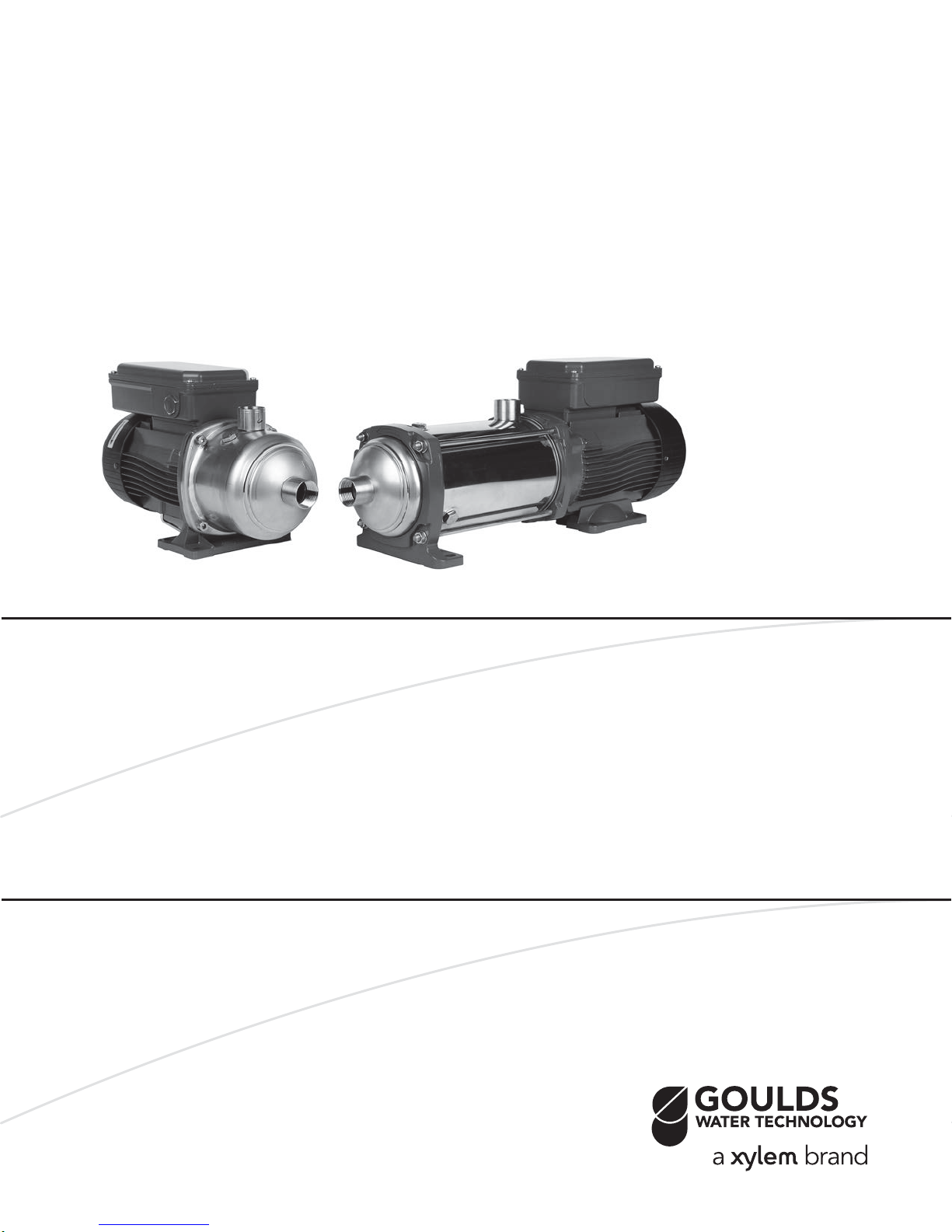
Installation, Operation, and
Maintenance Manual
Model e-HM
Page 2

Page 3

Table of Contents
1 Introduction and Safety.............................................................................................................................................................2
1.1 Introduction.................................................................................................................................................................................. 2
1.2 Inexperienced users.................................................................................................................................................................... 2
1.3 Safety terminology and symbols................................................................................................................................................2
1.4 Spare parts....................................................................................................................................................................................2
2 Transportation and Storage.......................................................................................................................................................2
2.1 Inspect the delivery..................................................................................................................................................................... 2
2.2 Transportation guidelines...........................................................................................................................................................2
2.3 Storage guidelines.......................................................................................................................................................................3
3 Product Description...................................................................................................................................................................3
3.1 Pump design................................................................................................................................................................................ 3
3.2 Application limits......................................................................................................................................................................... 3
3.3 The data plate.............................................................................................................................................................................. 3
4 Installation.................................................................................................................................................................................3
4.1 Facility requirements................................................................................................................................................................... 3
4.1.1 Pump location...................................................................................................................................................................... 3
4.1.2 Piping requirements............................................................................................................................................................4
4.2 Electrical requirements............................................................................................................................................................... 4
4.3 Install the pump........................................................................................................................................................................... 4
4.3.1 Install the pump on a concrete foundation...................................................................................................................... 4
4.3.2 Electrical installation............................................................................................................................................................5
5 Commissioning, Startup, Operation, and Shutdown.................................................................................................................5
5.1 Prime the pump........................................................................................................................................................................... 5
5.2 Check the rotation direction (three-phase motor)...................................................................................................................5
5.3 Start the pump..............................................................................................................................................................................5
6 Maintenance..............................................................................................................................................................................5
6.1 Service...........................................................................................................................................................................................6
6.2 Seal replacement......................................................................................................................................................................... 6
6.2.1 Disassembly..........................................................................................................................................................................6
6.2.2 Preassembly......................................................................................................................................................................... 9
6.2.3 Reassembly...........................................................................................................................................................................9
6.2.4 Torque values.....................................................................................................................................................................11
7 Troubleshooting.......................................................................................................................................................................11
7.1 Troubleshooting table.............................................................................................................................................................. 12
8 Product warranty.....................................................................................................................................................................12
Table of Contents
Model e-HM Installation, Operation, and Maintenance Manual 1
Page 4
Hazard level Indication
1 Introduction and Safety
1 Introduction and Safety
1.1 Introduction
Purpose of this manual
The purpose of this manual is to provide necessary information for:
• Installation
• Operation
• Maintenance
CAUTION:
Read this manual carefully before installing and using the
product. Improper use of the product can cause personal injury and damage to property, and may void the warranty.
NOTICE:
Save this manual for future reference, and keep it readily available at
the location of the unit.
1.2 Inexperienced users
WARNING:
This product is intended to be operated by qualified personnel only.
Be aware of the following precautions:
• Persons with diminished capacities should not operate the product unless they are supervised or have been properly trained by a
professional.
• Children must be supervised to ensure that they do not play on or
around the product.
1.3 Safety terminology and symbols
Hazard levels
H
DANGER:
WARNING:
CAUTION:
NOTICE:
A hazardous situation which, if not
avoided, will result in death or serious injury
A hazardous situation which, if not
avoided, could result in death or
serious injury
A hazardous situation which, if not
avoided, could result in minor or
moderate injury
• A potential situation which, if
not avoided, could result in
undesirable conditions
• A practice not related to personal injury
Description of user and installer symbols
Specific information for personnel in charge of installing
the product in the system (plumbing and/or electrical
aspects) or in charge of maintenance.
Specific information for users of the product.
1.4 Spare parts
WARNING:
Only use original spare parts to replace any worn or faulty
components. The use of unsuitable spare parts may cause
malfunctions, damage, and injuries as well as void the guarantee.
For more information about the product's spare parts, refer to the Sales
and Service department.
2 Transportation and Storage
2.1 Inspect the delivery
1. Check the outside of the package.
2. Notify our distributor within eight days of the delivery date, if the
product bears visible signs of damage.
3. Remove the staples and open the carton.
4. Remove the securing screws or the straps from the wooden base
(if any).
5. Remove packing materials from the product. Dispose of all packing materials in accordance with local regulations.
6. Inspect the product to determine if any parts have been damaged
or are missing.
7. Contact the seller if anything is out of order.
2.2 Transportation guidelines
Precautions
WARNING:
• Observe accident prevention regulations in force.
• Crush hazard. The unit and the components can be
heavy. Use proper lifting methods and wear steel-toed
shoes at all times.
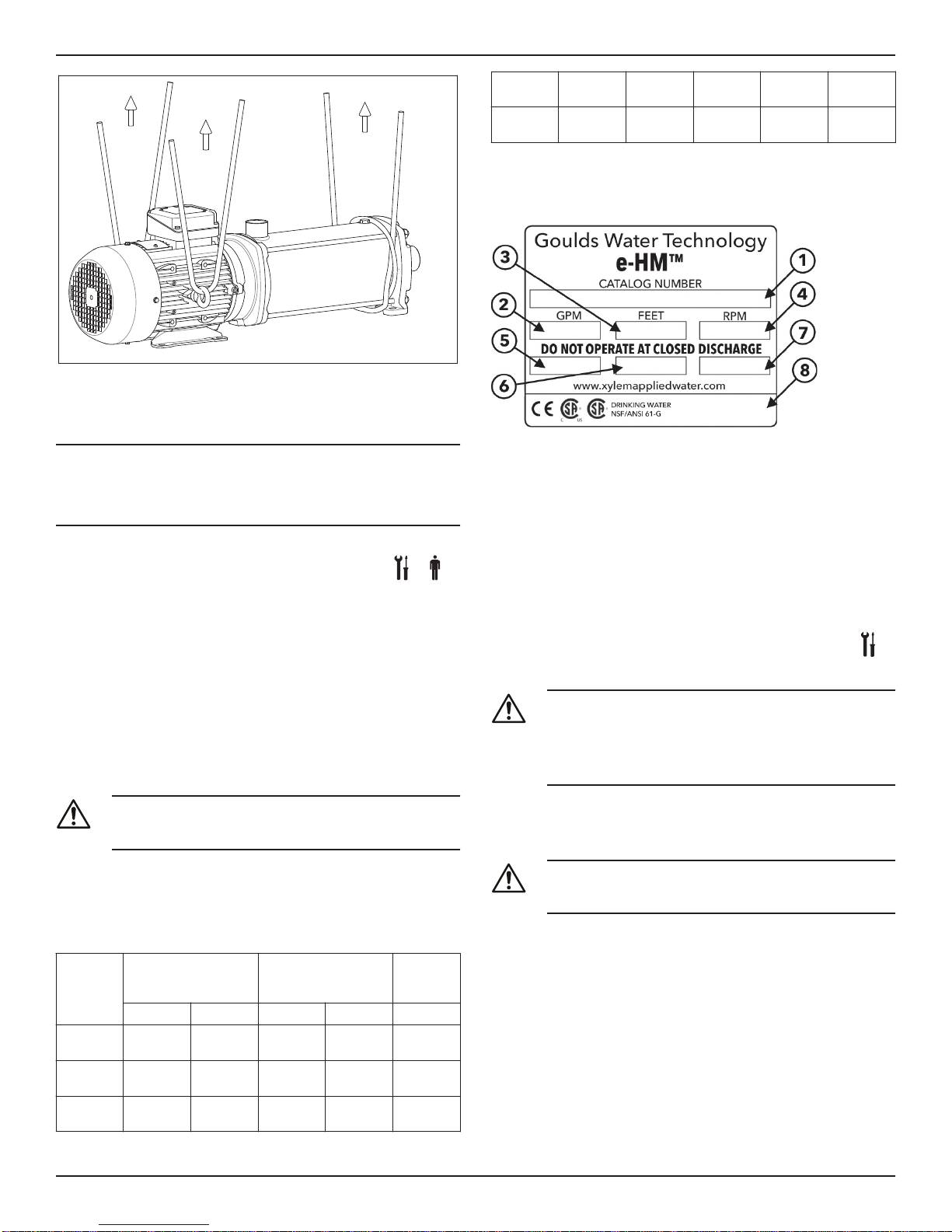
Check the gross weight that is indicated on the package in order to select proper lifting equipment.
Position and fastening
The unit can be transported either horizontally or vertically. Make sure
that the unit is securely fastened during transportation, and cannot roll
or fall over.
Hazard categories
Hazard categories can either fall under hazard levels or let
bols replace the ordinary hazard level symbols.
Electrical hazards are indicated by the following specific symbol:
Electrical Hazard:
Hot surface hazard
Hot surface hazards are indicated by a specific symbol that replaces the
typical hazard level symbols:
CAUTION:
2 Model e-HM Installation, Operation, and Maintenance Manual
specific sym-
Page 5
HM122_M043_B_sc
3 Product Description
2.3 Storage guidelines
Storage location
NOTICE:
• Protect the product against humidity, dirt, heat sources, and mechanical damage.
• The product must be stored at an ambient temperature from
-40°C to +60°C (-40°F to 140°F).
QQV 147PSI at
248F
BVE 147PSI at
194F
235PSI at
194F
Not Available
147PSI at
248F
147PSI at
194F
235PSI at
194F
Not Available
235PSI at
194F
Not Available
3.3 The data plate
The data plate is a label on the pump. The data plate lists key product
specifications.
1. Goulds Water Technology Catalog Number
2. Capacity range
3. TDH range
4. Rated speed
5. Rated horsepower
6. Maximum operating pressure
7. Maximum fluid temperature
8. Pump serial number
3 Product Description
3.1 Pump design
The pump is a multistage, non-self priming pump. The pump can be
used to pump:
• Cold water
• Warm water
Intended use
The pump is suitable for:
• Civil and industrial water distribution systems
• Irrigation (for example, agriculture and sporting facilities)
Improper use
DANGER:
Do not use this pump to handle flammable and/or explosive
liquids.
An improper use of the product leads to the loss of the warranty.
3.2 Application limits
Table 1: Pressure and temperature limits
Seal Code 1HM, 3HM 5HM 10HM,
2-6 Stages 7+ Stages 2-5 Stages 6+ Stages All Stages
BQE 147PSI at
248F
BQV 147PSI at
248F
QQE 147PSI at
248F
235PSI at
248F
235PSI at
248F
235PSI at
194F
147PSI at
248F
147PSI at
248F
147PSI at
248F
235PSI at
248F
235PSI at
248F
235PSI at
194F
15HM,
22HM
235PSI at
248F
235PSI at
248F
235PSI at
194F
IMQ or other marks (for electric pump only)
Unless otherwise specified, for products with a mark of electrical-related safety approval, the approval refers exclusively to the electrical
pump.
4 Installation
Precautions
WARNING:
• Observe accident prevention regulations in force.
• Use suitable equipment and protection.
• Always refer to the local and/or national regulations,
legislation, and codes in force regarding the selection of
the installation site, plumbing, and power connections.
4.1 Facility requirements
4.1.1 Pump location
DANGER:
Do not use this unit in environments that may contain flammable/explosive or chemically aggressive gases or powders.
Guidelines
Observe the following guidelines regarding the location of the product:
•
Make sure that no obstructions hinder the normal
ing air that is delivered by the motor fan.
•
Make sure that the installation area is protected from any fluid
leaks, or flooding.
• If possible, place the pump slightly higher than the floor level.
• The ambient temperature must be between -30°C (-22°F) and
+40°C (+104°F) unless otherwise specified in the data plate.
• The relative humidity of the ambient air must be less than 50% at
+40°C (+104°F).
of the cool-
flow
Model e-HM Installation, Operation, and Maintenance Manual 3
Page 6
Pump Type Protection
4 Installation
Installation above liquid source (suction lift)
The theoretical maximum suction height of any pump is 34 ft. In practice, this is not achieved due to the following conditions affecting the
suction capability of the pump:
• Temperature of the liquid
• Elevation above the sea level (in an open system)
• System pressure (in a closed system)
• Resistance of the pipes
• Own intrinsic flow resistance of the pump
• Height differences
NOTICE:
Do not exceed the pumps suction capacity as this could cause cavitation and damage the pump.
4.1.2 Piping requirements
Precautions
CAUTION:
• Use pipes suited to the maximum working pressure of
the pump. Failure to do so can cause the system to rupture, with the risk of injury.
• Make sure that all connections are performed by qualified installation technicians and in compliance with the
regulations in force.
• Do not use the on-off valve on the discharge side in the
closed position for more than a few seconds. If the
pump must operate with the discharge side closed for
more than a few seconds, a bypass circuit must be installed to prevent overheating of the water inside the
pump.
Piping checklist
• Pipes and valves must be correctly sized.
• Pipe work must not transmit any load or torque to pump flanges.
The electrical control panel checklist
NOTICE:
The control panel must match the ratings of the electric pump. Improper combinations could fail to guarantee the protection of the motor.
Check that the following requirements are met:
• The control panel must protect the motor against overload and
short-circuit.
• Install the correct overload protection (thermal relay or motor protector).
P
Single phase standard electric
pump up to 3 HP
Three-phase electric pump • Thermal protection (must
• The control panel must be equipped with a dry-running protection system to which a pressure switch, float switch, sensors, or
other suitable device is connected.
• The following devices are recommended for use on the suction
side of the pump:
• When the liquid is pumped from a water system, use a pressure switch.
• When the liquid is pumped from a storage tank or reservoir,
use a float switch or sensors.
• When thermal relays are used, relays that are sensitive to phase
failure are recommended.
• Built-in automatic reset
thermal-overload protection
• Short circuit protection
(must be supplied by the
installer)
be supplied by the installer)
• Short circuit protection
(must be supplied by the
installer)
4.2 Electrical requirements
• The local regulations in force overrule these specified requirements. In the case of fire fighting systems (hydrants and/or sprinklers), check the local regulations.
Electrical connection checklist
Check that the following requirements are met:
• The electrical leads are protected from high temperature, vibrations, and collisions.
• The power supply line is provided with:
• A short-circuit protection device
• A main disconnect switch.
The motor checklist
Use cable according to rules with 3 leads (2+earth/ground) for single
phase versions and with 4 leads (3+earth/ground) for three-phase version.
4.3 Install the pump
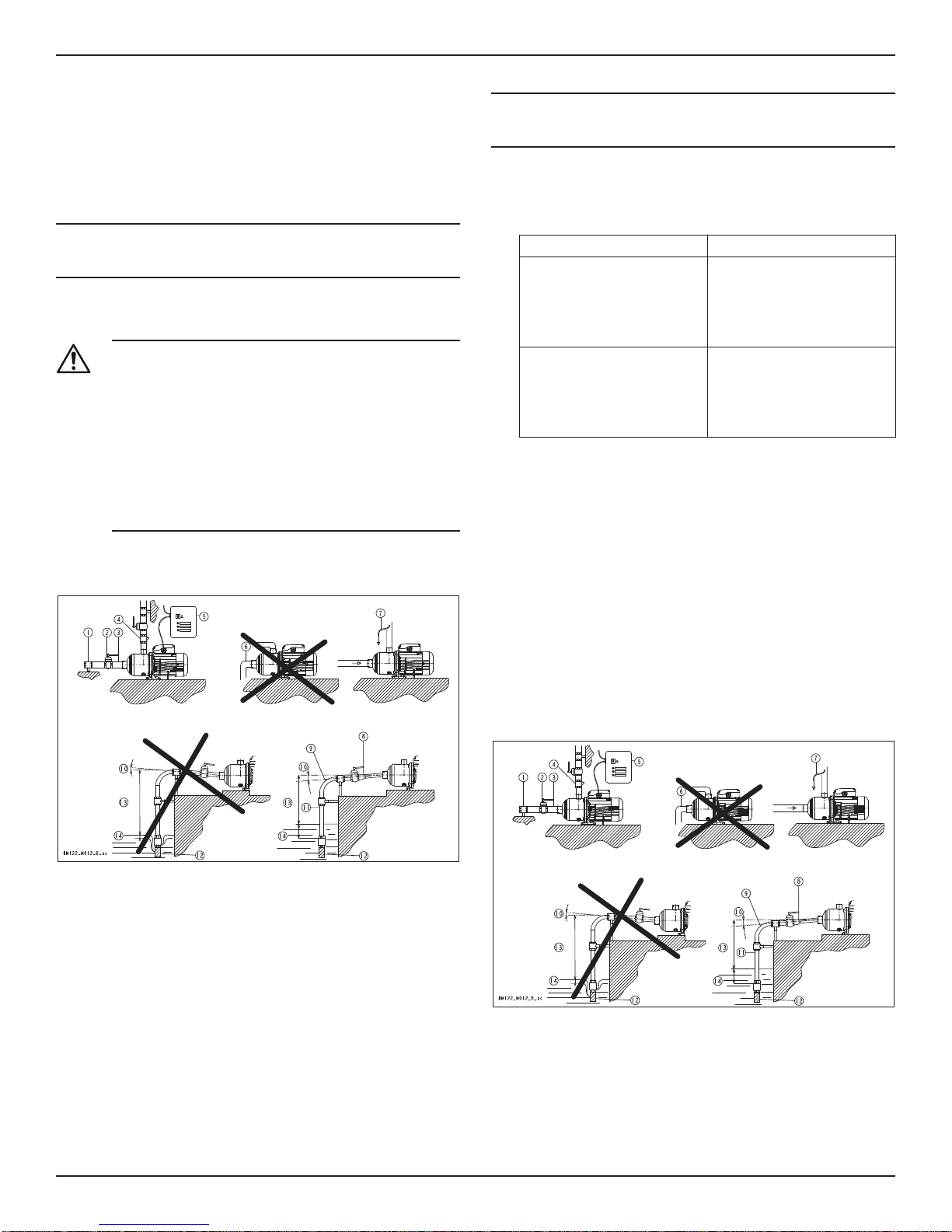
4.3.1 Install the pump on a concrete foundation
1. Piping support
2. On-off valve
3. Flexible pipe or joint
4. Check valve
5. Control panel
6. Do not install elbows close to the pump
7. Bypass circuit
8. Eccentric reducer
9. Use wide bends
10. Positive gradient
11. Piping with equal or greater diameter than the suction port
4 Model e-HM Installation, Operation, and Maintenance Manual
Page 7
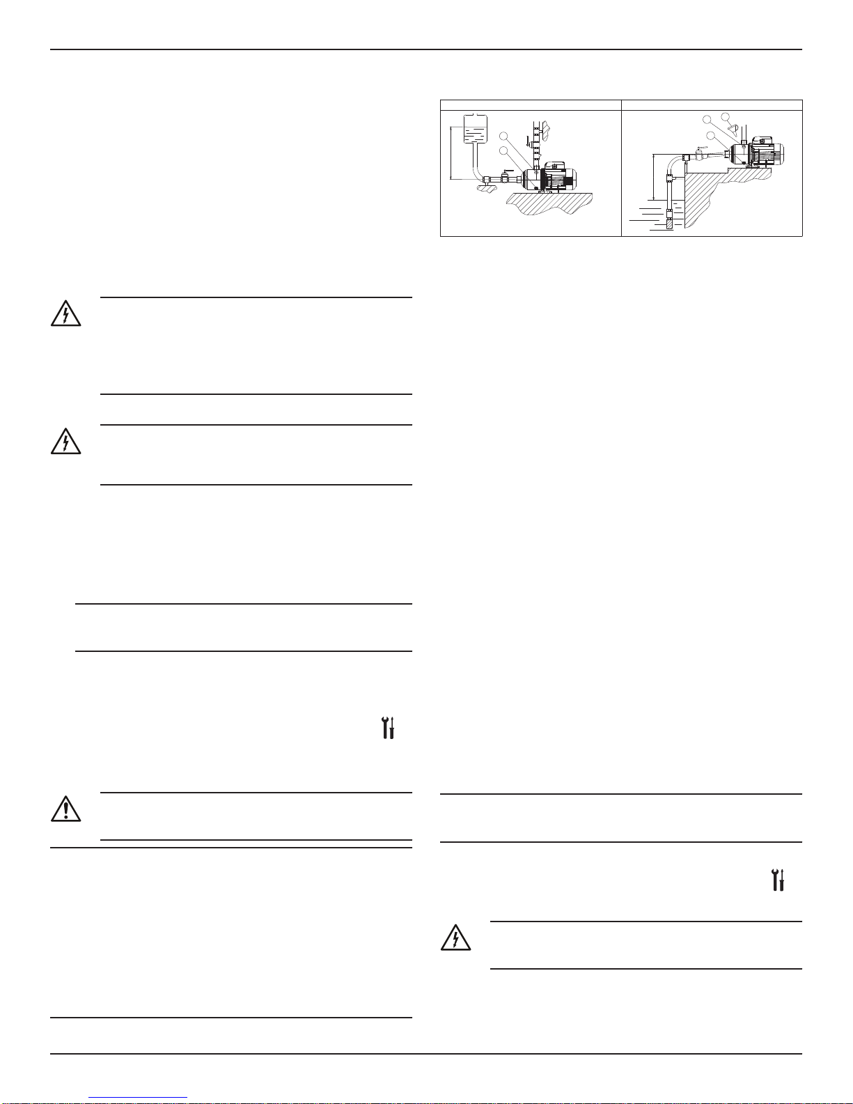
12. Use foot valve
H>0
H<0
+H
-H
1
2
1
2
3
HM122_M014_A_sc
13. Do not exceed maximum height difference
14. Ensure adequate submersion depth
1. Anchor the pump onto the concrete or equivalent metal structure.
• If the liquid temperature exceeds 50°C, the unit must be
anchored only by the motor bracket side and not also by the
side of the inlet supporting bracket
• If the transmission of vibrations can be disturbing, then provide vibration-damping supports between the pump and the
foundation.
2. Remove the plugs covering the ports.
3. Assemble the pipe to the pump threaded connections.
Do not force the piping into place.
4.3.2 Electrical installation
Precautions
Electrical Hazard:
• Make sure that all connections are performed by qualified installation technicians and in compliance with the
regulations in force.
• Before starting work on the unit, make sure that the unit
and the control panel are isolated from the power supply and cannot be energized.
Grounding (earthing)
Electrical Hazard:
• Always connect the external protection conductor to
ground (earth) terminal before making other electrical
connections.
Connect the cable
1. Connect and fasten the power cables according to the wiring diagram under the terminal box cover.
a) Connect the ground (earth) lead.
Make sure that the ground (earth) lead is longer than the
phase leads.
b) Connect the phase leads.
NOTICE:
Tighten the cable glands carefully to ensure the protection against
the cable slipping and humidity entering the terminal box.
2. If the motor is not equipped with automatic reset thermal protection, then adjust the overload protection according to the nominal
current value of electric pump (data plate).
5 Commissioning, Startup,
Operation, and Shutdown
Precautions
WARNING:
Make sure that the drained liquid does not cause damage or
injuries.
5 Commissioning, Startup, Operation, and Shutdown
5.1 Prime the pump
1. Fill plug
2. Drain plug
3. Funnel
Installations with liquid level above the pump (suction head)
Close the on-off valve located downstream from the pump.
Installations with liquid level below the pump (suction lift)
Open the on-off valve that is located upstream from the pump and
close the on-off valve downstream.
5.2 Check the rotation direction (three-phase
motor)
Follow this procedure before start-up.
1. Start the motor.
2. Stop the motor.
3. If the rotation direction is incorrect, then do as follows:
a) Disconnect the power supply.
b) In the terminal board of the motor or in the electric control
panel, exchange the position of two of the three wires of the
supply cable.
c) Check the direction of rotation again.
5.3 Start the pump
1. Start the motor.
2. Gradually open the on-off valve on the discharge side of the
pump.
At the expected operating conditions, the pump must run
smoothly and quietly. If not, refer to Troubleshooting (page 11).
3. If the pump does not start in correctly in 30 seconds, then do the
following:
a) Switch off the pump.
b) Reprime the pump.
c) Start the pump again.
4. Switch off and on the pump (for about 30 seconds of continuos
running) and make sure that all the trapped air is bled out by repeating this 2–3 times.
NOTICE:
Make sure that the pump has bled away all the trapped air. Failure to
do so can harm the product.
NOTICE:
Never operate the pump below the minimum rated flow.
•
•
Never operate the pump with the delivery ON-OFF valve closed
for longer than a few seconds.
• Do not expose an idle pump to freezing conditions. Drain all liquid that is inside the pump. Failure to do so can cause liquid to
freeze and damage the pump.
• The sum of the pressure on the suction side (water mains, gravity
tank) and the maximum pressure that is delivered by the pump
must not exceed the maximum working pressure that is allowed
(nominal pressure PN) for the pump.
• Do not use the pump if cavitation occurs. Cavitation can damage
the internal components.
Model e-HM Installation, Operation, and Maintenance Manual 5
6 Maintenance
Precautions
Electrical Hazard:
Disconnect and lock out electrical power before installing or
servicing the unit.
Page 8
6 Maintenance
WARNING:
• Maintenance and service must be performed by skilled
and qualified personnel only.
• Observe accident prevention regulations in force.
• Use suitable equipment and protection.
6.1 Service
The pump does not require any scheduled routine maintenance. If the
user wishes to schedule regular maintenance deadlines, they are dependent on the type of pumped liquid and on the operating conditions
of the pump.
Contact the local sales and service representative for any requests or
information regarding routine maintenance or service.
6.2 Seal replacement
1. Close all necessary suction and discharge valves.
2. Remove the lower drain plug and the upper vent plug to drain the
liquid from the pump.
6.2.1 Disassembly
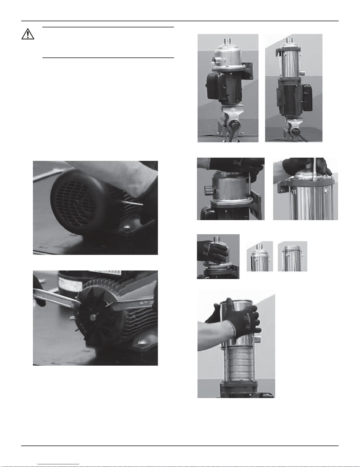
1. Remove two motor fan cover screws and remove motor fan cover.
3. Lock shaft with a screwdriver or a soft jaw vice.
4. Remove four (4) casing studs (Compact design) or four (4) tie rod
nuts and washers (Sleeve design).
2. Remove motor fan using two small flat bars or two large screwdrivers.
5. Remove casing (Compact design) or pump foot and suction head
(Sleeve design).
6. Remove sleeve (Sleeve design).
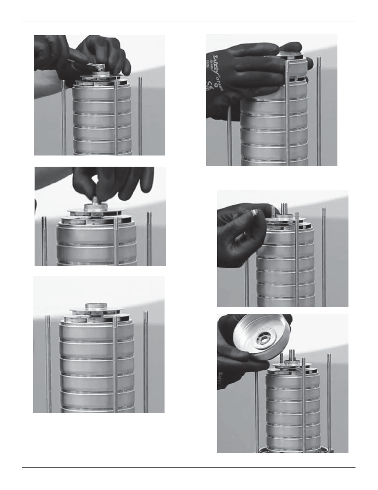
6 Model e-HM Installation, Operation, and Maintenance Manual
7. Remove first stage bowl.
Page 9
6 Maintenance
8. Remove shaft screw/impeller nut.
9. Remove impeller spacer.
11. For non-bearing stage, remove diffuser.
12. Remove impeller spacer.
13. For bearing stages use steps 15 - 17.
a) Remove bearing washer.
10. Remove impeller.
b) Remove diffuser.
Model e-HM Installation, Operation, and Maintenance Manual 7
Page 10
6 Maintenance
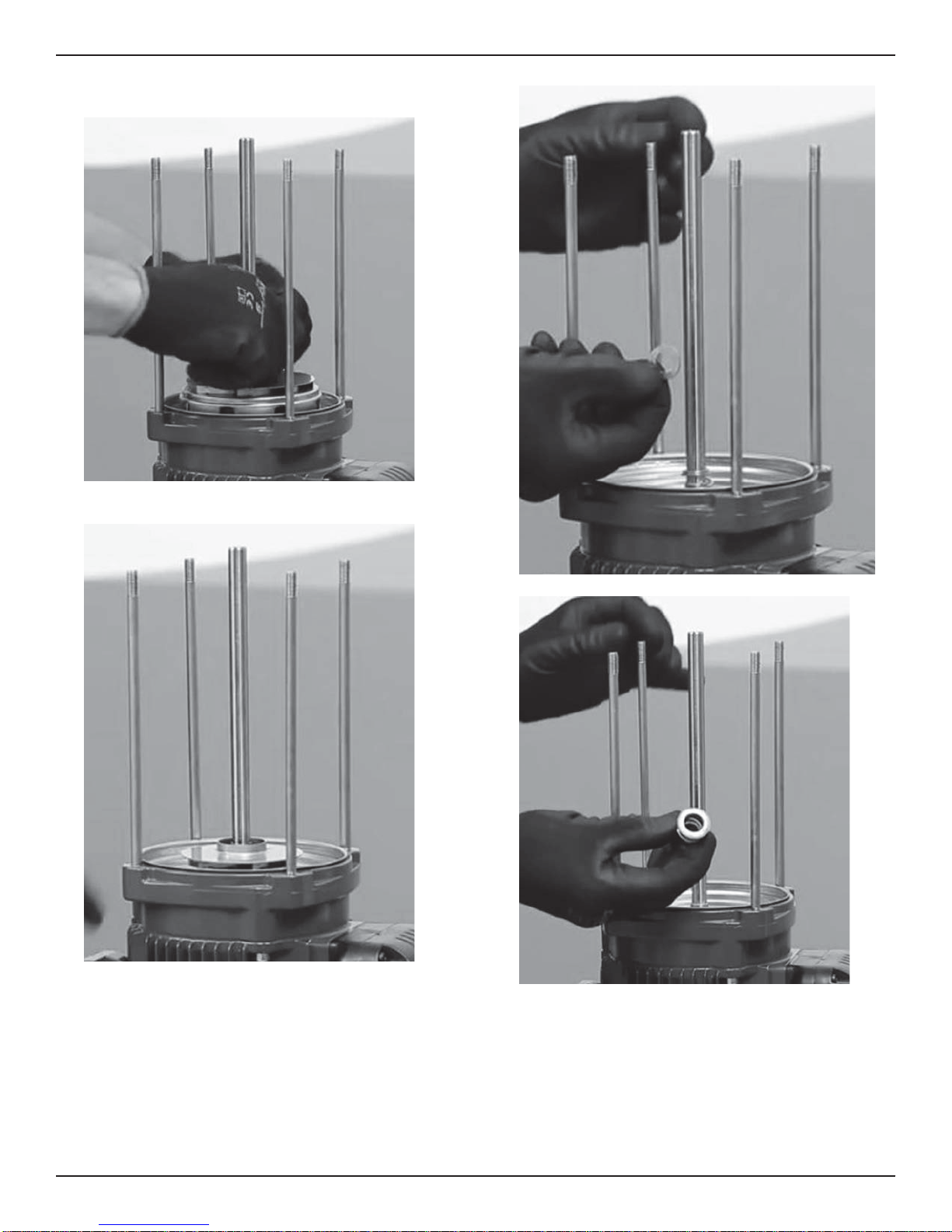
c) Remove bearing.
d) Repeat a through c for all intermediate stages.
14. Remove last stage diffuser.
15. Remove impeller spacer.
16. Remove impeller.
17. Remove seal spacer.
18. Remove rotating seal.
8 Model e-HM Installation, Operation, and Maintenance Manual
Page 11
6 Maintenance
19. Remove seal housing.
20. Press out stationary seal from seal housing.
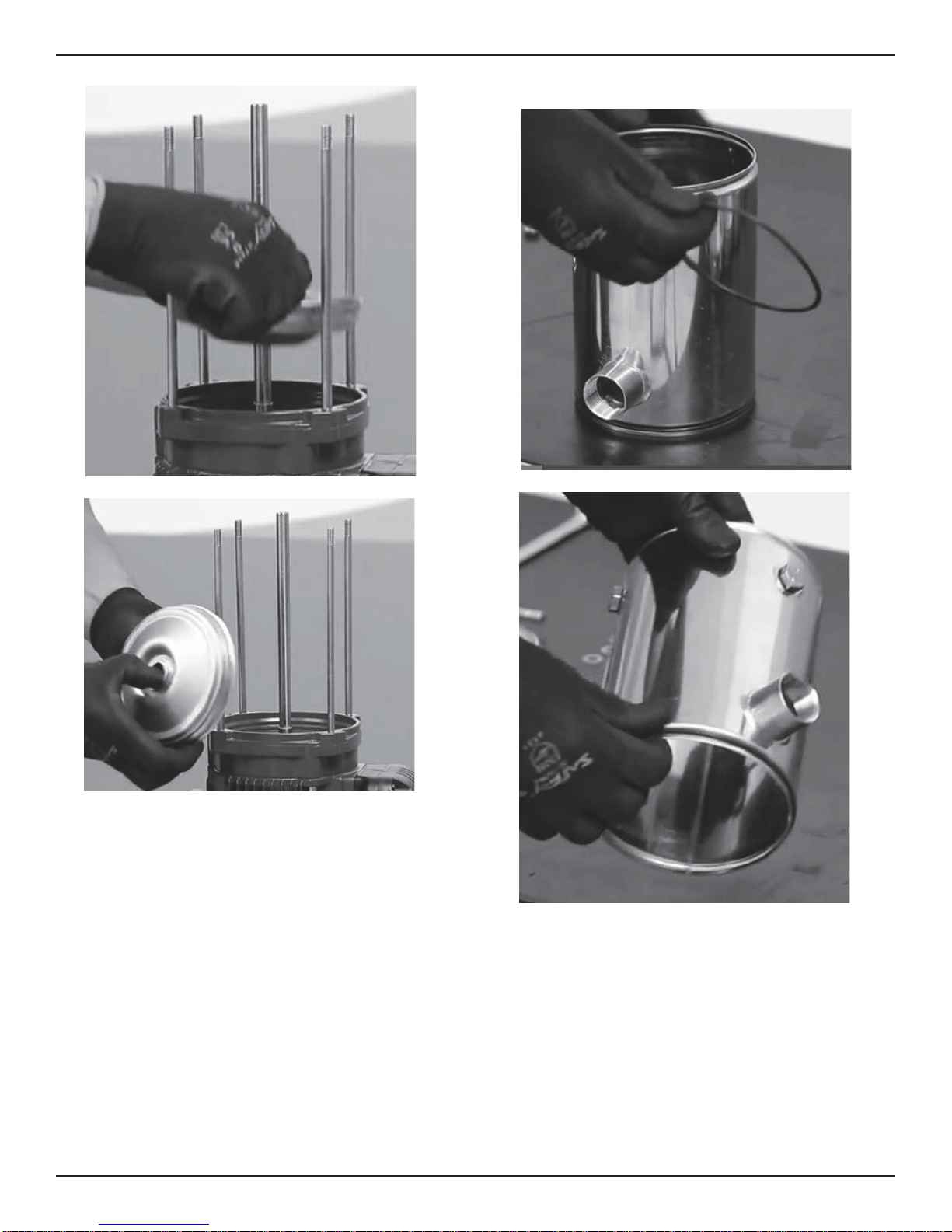
6.2.2 Preassembly
1. Remove sleeve O-ring on suction end (Sleeve design).
2. Remove sleeve O-ring on motor end (Sleeve design).
Model e-HM Installation, Operation, and Maintenance Manual 9
Note: Properly dispose of sleeve O-rings and mechanical seal
parts. Do not reuse.
3. Install new sleeve O-ring on suction end (Sleeve design).
4. Install new sleeve O-ring on motor end (Sleeve design).
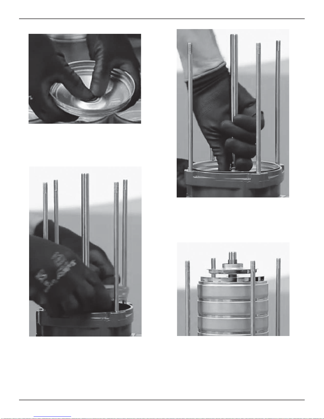
6.2.3 Reassembly
1. Inspect and clean the inside the pump casing and inside bore of
seal housing removing any debris.
2. Lubricate ID of seal housing and ID of seal with water or P-80.
3. Remove new rotating and stationary seal elements from packaging, inspect for damage and clean with water.
Page 12
6 Maintenance
4. Insert the new stationary seal seat into the seal bore of the seal
housing with the seal face out.
a) DO NOT scratch or damage the seal face.
b) Ensure that the seal is seated firmly and squarely inside the
seal bore.
c) With a clean lint-free cloth or alcohol swab, wipe the seal face
clean of all lubricant or debris.
d) DO NOT use grease or heavy lubricants to install seal, as
these materials can cause the seal to leak.
5. Install seal housing.
to turn initially, the seal is seated properly.
6. Rotate the rotary portion of the mechanical seal on the pump shaft
until it “locks” and you are unable to turn freely. If you are unable
7. Install seal spacer.
8. Install impeller.
9. Install last stage diffuser.
10. Install impeller spacer.
11. Install impeller.
12. Install impeller spacer.
13. Install diffuser.
14. Repeat 10–13 for all intermediate stages.
For bearing stages, use steps 15 - 17.
15. Install bearing.
10 Model e-HM Installation, Operation, and Maintenance Manual
Page 13
Pump size Tie rod nuts Vent / drain plug
Casing bolts / tie rods
Impeller screw
7 Troubleshooting
16. Install bearing diffuser.
17. Install spacer.
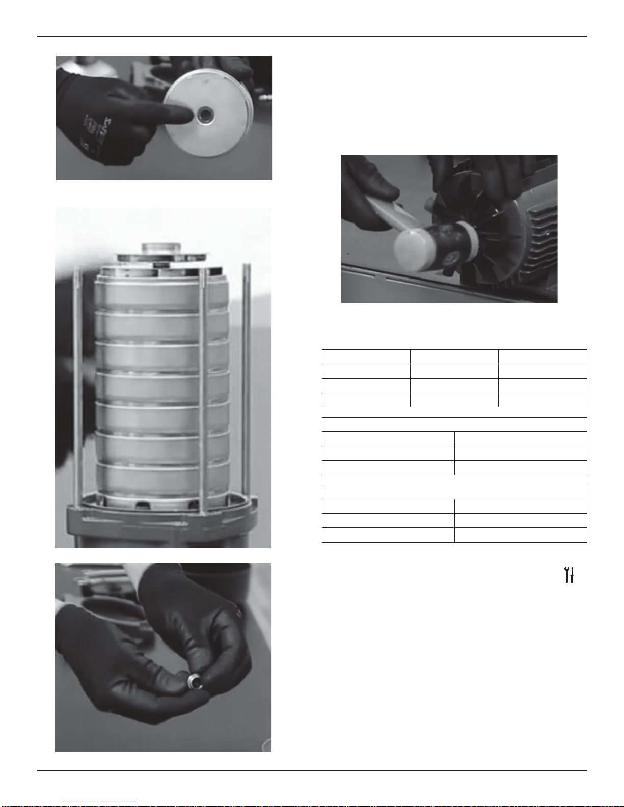
18. Install first stage impeller.
20. Install shaft screw/impeller nut.
21. Install first stage bowl.
22. Install sleeve (Sleeve design) by pressing into the seal housing for
a tight O-ring fit.
23. Install casing (Compact design) or suction head (Sleeve design).
24. Install pump foot (Sleeve design).
25. Install four (4) casing studs (Compact design) or four (4) washers
and tie rod nuts (Sleeve design).
26. Install motor fan onto motor shaft. Using a rubber mallet, gently
tap the fan into place against motor housing.
27. Place motor fan cover over fan and cooling fins, and install two
cover screws.
6.2.4 Torque values
19. Install impeller spacer.
P
1-5SV 22 lbs ft (30 N m) 15 lbs ft (20 N m)
10-22SV 37 lbs ft (50 N m) 15 lbs ft (20 N m)
33-125SV 44 lbs ft (60 N m) 29 lbs ft (40 N m)
One piece pump body (1–3–5HM) 11 ft-lb
Sleeved Units (1-3-5HM) 10 ft-lb
Sleeved Units (10-15-22HM) 18.5 ft-lb
One piece pump body (1–3–5HM) 6 ft-lb
Sleeved Units (1-3-5HM) 15 ft-lb
Sleeved Units (10-15-22HM) 26 ft-lb
7 Troubleshooting
Introduction
Always specify the exact pump type and identification code when requesting information or spare parts from the Sales and Service department.
For other situation not mentioned in the table, refer to the Sales and
Service department.
Model e-HM Installation, Operation, and Maintenance Manual 11
Page 14

Problem Cause and solution
Warranty.
THE FOREGOING WARRANTY IS EXCLUSIVE AND IN LIEU OF ANY
AND ALL OTHER EXPRESS OR IMPLIED WARRANTIES, GU
ARANTEES,
CONDITIONS OR TERMS OF WHATEVER NATURE RELATING TO THE
GOODS PROVIDED HEREUNDER, INCLUDING WITHOUT LIMITATION
ANY IMPLIED WARRANTIES OF MERCHANTABILITY AND FITNESS
FOR A PARTICULAR PURPOSE, WHICH
ARE HEREBY EXPRESSLY DISCLAIMED AND EXCLUDED. EXCEPT AS OTHERWISE REQUIRED BY
LAW, BUYER’S EXCLUSIVE
REMEDY AND SELLER’S AGGREGATE LIABILITY FOR BREACH OF ANY OF THE FOREGOING WARRANTIES ARE
LIMITED TO
REPAIRING OR REPLACING THE PRODUCT AND SHALL
IN ALL CASES BE LIMITED TO THE AMOUNT PAID BY THE BUYER FOR
THE DEFECTIVE PRODUCT. IN NO EVENT SHALL SELLER BE LIABLE
FOR ANY OTHER FORM OF DAMAGES, WHETHER DIR
ECT, INDIRECT,
LIQUIDATED, INCIDENTAL, CONSEQUENTIAL, PUNITIVE, EXEMPLARY
OR SPECIAL DAMAGES, INCLUDING BUT NOT LIMITED TO LOSS OF
PROFIT, LOSS OF ANTICIPATED SAVINGS OR REVENUE, LOSS OF INCOME, LOSS OF BUSINESS, LOSS OF PRODUCTION, LOSS OF OPPORTUNITY OR LOSS OF REPUTATION.
Warranty.
THE FOREGOING WARRANTY IS PROVIDED IN PLACE OF ALL OTHER
EXPRESS WARRANTIES. ALL IMPLIED WARRANTIES, INCLUDING BUT
NOT LIMITED TO THE IMPLIED WARRANTIES OF MERCHANTABILITY
AND FITNESS FOR A PARTICULAR PURPOSE, ARE LIMITED TO ONE
(1) YEAR FROM THE DATE OF INSTALLATION OR EIGHTEEN (18)
MONTHS FROM THE PRODUCT
DATE CODE , WHICHEVER SHALL
OCCUR FIRST. EXCEPT AS OTHERWISE REQUIRED BY LAW, BUYER’S
8 Product warranty
7.1 Troubleshooting table
P
The pump does
not start.
The pump starts
up but the thermal protector is
triggered after a
short time or the
fuses blow.
The pump starts
but does not deliver any liquid.
The pump’s delivery is reduced.
• The thermo-overload protection in the singlephase motor has tripped; it will automatically
reset when the motor cools down.
• Check the power supply wiring to see that the
connections are all tight
• Check to see that the circuit breaker or groundfault protection device has tripped. Or replace
any fuses that may have blown.
• Check to see if any protection device installed
for dry running protection has tripped or hung
up.
• The power supply cable is damaged, the motor
short circuits or thermal protector or fuses are
not suited for the motor current. Check and replace the components as necessary.
• The thermo-overload protection (single phase)
or of the protection device (three-phase) trips
due to excessive current input. Check the
pump working conditions.
• A phase in the power supply is missing. Check
the power supply.
• The pump is clogged with solids and the impeller becomes bound. Clean the pump.
• Air is entering the suction piping, check the liquid level, the tightness of the suction pipes and
the operation of the foot valve.
• The pump is not correctly primed. Repeat the
instructions in Prime the pump (page 5).
• Check for restrictions in the piping system.
• Wrong rotation of the impeller (three-phase).
Check the direction of rotation.
• The pump is not correctly primed. Repeat the
instructions in Prime the pump (page 5).
8 Product warranty
Commercial warranty
goods sold to Buyer hereunder (with the exception of membranes,
seals, gaskets, elastomer materials, coatings and other "wear parts" or
consumables all of which are not warranted except as otherwise provided in the quotation or sales form) will be (i) be built in accordance
with the specifications referred to in the quotation or sales form, if such
specifications are expressly made a part of this Agreement, and (ii) free
from defects in material and workmanship for a period of one (1) year
from the date of installation or eighteen (18) months from the date of
shipment (which date of shipment shall not be greater than thirty (30)
days after receipt of notice that the goods are ready to ship), whichever
shall occur first, unless a longer period is specified in the product documentation (the “Warranty”).
Except as otherwise required by law, Seller shall, at its option and at no
cost to Buyer, either repair or replace any product which fails to conform with the Warranty provided Buyer gives written notice to Seller of
any defects in material or workmanship within ten (10) days of the date
when any defects or non-conformance are first
repair or replacement option, Seller shall not be obligated to remove
or pay for the removal of the defective product or install or pay for the
installation of the replaced or repaired product and Buyer shall be responsible for all other costs, including, but not limited to, service costs,
shipping fees and expenses. Seller shall have sole discretion as to the
method or means of repair or replacement. Buyer’s failure to comply
with Seller’s repair or replacement directions shall terminate Seller’s
obligations under this Warranty and render the Warranty void. Any
parts repaired or replaced under the Warranty are warranted only for
the balance of the warranty period on the parts that were repaired or
replaced. Seller shall have no warranty obligations to Buyer with respect to any product or parts of a product that have been: (a) repaired
by third parties other than Seller or without Seller’s written approval;
(b) subject to misuse, misapplication, neglect, alteration, accident, or
For goods sold to commercial buyers, Seller warrants the
manifest. Under either
physical damage; (c) used in a manner contrary to Seller’s instructions
for installation, operation and maintenance; (d) damaged from ordinary wear and tear, corrosion, or chemical attack; (e) damaged due to abnormal conditions, vibration, failure to properly prime, or operation
without
electrical protection; or (g) damaged resulting from the use of accessory equipment not sold or approved by Seller. In any case of products
not manufactured by Seller, there is no warranty from Seller; however,
Seller will extend to Buyer any warranty received from Seller’s supplier
of such products.
Limited consumer warranty
Seller warrants the goods purchased hereunder (with the exception of
membranes, seals, gaskets, elastomer materials, coatings and other
"wear parts" or consumables all of which are not warranted except as
otherwise provided in the quotation or sales form) will be free from defects in material and workmanship for a period of one (1) year from the
date of installation or eighteen (18) months from the product date
code, whichever shall occur first, unless a longer period is provided by
law or is specified in the product documentation (the “Warranty”).
Except as otherwise required by law, Seller shall, at its option and at no
cost to Buyer, either repair or replace any product which fails to conform with the Warranty provided Buyer gives written notice to Seller of
any defects in material or workmanship within ten (10) days of the date
when any defects or non-conformance are first manifest. Under either
repair or replacement option, Seller shall not be obligated to remove
or pay for the removal of the defective product or install or pay for the
installation of the replaced or repaired product and Buyer shall be responsible for all other costs, including, but not limited to, service costs,
shipping fees and expenses. Seller shall have sole discretion as to the
method or means of repair or replacement. Buyer’s failure to comply
with Seller’s repair or replacement directions shall terminate Seller’s
obligations under this Warranty and render this Warranty void. Any
parts repaired or replaced under the Warranty are warranted only for
the balance of the warranty period on the parts that were repaired or
replaced. The Warranty is conditioned on Buyer giving written notice to
Seller of any defects in material or workmanship of warranted goods
within ten (10) days of the date when any defects are first manifest.
Seller shall have no warranty obligations to Buyer with respect to any
product or parts of a product that have been: (a) repaired by third parties other than Seller or without Seller’s written approval; (b) subject to
misuse, misapplication, neglect, alteration, accident, or physical damage; (c) used in a manner contrary to Seller’s instructions for installation, operation and maintenance; (d) damaged from ordinary wear and
tear, corrosion, or chemical attack; (e) damaged due to abnormal conditions, vibration, failure to properly prime, or operation without flow;
(f) damaged due to a defective power supply or improper electrical
protection; or (g) damaged resulting from the use of accessory equipment not sold or approved by Seller. In any case of products not manufactured by Seller, there is no warranty from Seller; however, Seller will
extend to Buyer any warranty received from Seller’s supplier of such
products.
(f) damaged due to a defective power supply or improper
flow;
For goods sold for personal, family or household purposes,
12 Model e-HM Installation, Operation, and Maintenance Manual
Page 15

E
EXCLUSIVE REMEDY AND SELLER’S AGGREGATE LIABILITY FOR
BREACH OF ANY OF THE FOREGOING WARRANTIES ARE LI
MITED TO
REPAIRING OR REPLACING THE PRODUCT AND SHALL IN ALL CASES
BE LIMITED TO THE AMOUNT PAID BY THE
BUYER FOR THE DEFECTIVE PRODUCT. IN NO EVENT SHALL SELLER BE LIABLE FOR ANY
OTHER FORM OF DAMAGES, W
HETHER DIRECT, INDIRECT, LIQUIDATED, INCIDENTAL, CONSEQUENTIAL, PUNITIVE, EXEMPLARY OR
SPECIAL DAMAGE
S, INCLUDING BUT NOT LIMITED TO LOSS OF
PROFIT, LOSS OF ANTICIPATED SAVINGS OR REVENUE, LOSS OF INCOME, LOSS OF BUSINESS, LOSS OF PRODUCTION, LOSS OF OPPORTUNITY OR LOSS OF REPUTATION.
Some states do not allow limitations on how long an implied warranty
lasts, so the above limitation may not apply to you. Some states do not
allow the exclusion or limitation of incidental or consequential damages, so the above exclusions may not apply to you. This warranty gives
you specific legal rights, and you may also have other rights which may
vary from state to state.
To make a warranty claim, check first with the dealer from whom you
purchased the product or visit www.xyleminc.com for the name and location of the nearest dealer providing warranty service.
8 Product warranty
Model e-HM Installation, Operation, and Maintenance Manual 13
Page 16

Xylem |’zīlәm|
For more information on how Xylem can help you, go to xyleminc.com
1) The tissue in plants that brings water upward from the roots
2) A leading global water technology company
We're 12,500 people unified in a common purpose: creating innovative solutions to meet our world's
water needs. Developing new technologies that will improve the way water is used, conserved, and
re-used in the future is central to our work. We move, treat, analyze, and return water to the
environment, and we help people use water efficiently, in their homes, buildings, factories and farms.
In more than 150 countries, we have strong, long-standing relationships with customers who know us
for our powerful combination of leading product brands and applications expertise, backed by a
legacy of innovation.
F
Xylem Inc.
2881 East Bayard Street, Suite A
Seneca Falls, NY 13148
USA
Tel: (866) 325-4210
Fax: (888) 322-5877
Visit our Web site for the latest version of this document
and more information
The original instruction is in English. All non-English
instructions are translations of the original instruction.
©
2015 Xylem Inc
Goulds is a registered trademark of Goulds Pumps, Inc.
and is used under license.
IM254R02
 Loading...