

Gould 8002 Technical Manual
y\
\J
Gould
Publication
Multi-Function
Model
Tedllnical
':,-'),.,'f.:
Order
8002
Manual
Number:.30:i.-006540-000
Processor
.
'",~
(:
,"",
".
GOU,lD·----
'
..
Electro
•.

" r
(
HISTORY
The
Gould Multi-Function Processor Technical Manual, Publication
006540-000,
This
manual contains
was printed June, 1987.
the
following pages:
Title page
Copyright page
iii (iv Blank)
v through xiii (xiv Blank)
1-1
through 1-9 (1-10 Blank)
2-1
through 2-21 (2-22 Blank)
3-1
through 3-13 (3-14 Blank)
4-1
through 4-33 (4-34 Blank)
5-1
through 5-8
6-1
through 6-32
IN-l
through IN-4
Order
Number
303-
iii
(iv
Blank)

TABLE
OF
CONTENTS
Chapter
List of Illustrations ......................................................................................................................... xi
List of
1 - General Description
1.1
1.2
1.3
1.4 Functional Description ......................................................................................................... 1-6
1.5
1.6
2 - Controls, Indicators, and Connectors
2.1
2.2 Controls, Indicators, and Connectors, MFP Circuit
2.3 Controls, Indicators, and Connectors, MFP DI
Tables
Introduction ..........................................................................................................................
Features
Physical Description .............................................................................................................
1.3.1
'1.3.2
1.3.3 Secondary General Purpose Device Interface Circuit
1.4.1
1.4.2 Asynchronous Communications
1.4.3
1.4.4
Software ................................................................................................................................ 1-8
Specifications ......................................................................................................................... 1-8
Introduction ..........................................................................................................................
2.2.1 Controls,
2.2.2 Indicators,
2.2.3 Connectors,
2.3.1 Jumpers,
2.3.2 Connectors, MFP
............................................................................................................................... xiii
.................................................................................................................................
MFP
Circuit
MFP
Device Interface Circuit
SCSI
Ports
Parallel
System
2.2.1.1
2.2.1.2 Jumpers, MFP Circuit
2.2.3.1 Connector
2.2.3.2 Connectors J2 and J3, ROM-SIM .................................................................
2.2.3.3 Connector J4, Y-Bus ...................................................................................... 2-9
2.3.2.1 Connector
2.3.2.2 Connector J2,
2.3.2.3 Connector J3, Asynchronous
2.3.2.4 Connector J4, Asynchronous
2.3.2.5 Connector J5, External
2.3.2.6 Connector J7, Line
2.3.2.7 Connector J8, Turnkey Panel .................................................................... 2-19
Card
...................................................................................................... 1-3
Card
.........................................................................
Card
................................... 1-6
.................................................................................................................. 1-8
Ports
...................................................................... 1-8
Printer
Timer
On
Port
................................................................................................. 1-8
............................................................................................................. 1-8
Card
................................................
MFP
Circuit
Line/Off Line Switch,
MFP
MFP
MFP
DI
Card
.....................................................................................
MFP
Circuit
Card
........................................................................
Circuit Card .................................................................................. 2-6
Circuit Card ................................................................................. 2-8
Jl,
Address and Control... ...........................................................
Circuit
DI
Jl,
Card
.............................................................................. 2-12
Circuit
SCSI Bus 1. .......................................................................... 2-15
SCSI Bus 2 ........................................................................... 2-16
Card
Interrupts
Printer
......................................................................... 2-15
Ports
Ports
......................................................................... 2-19
Card
.............................................
Circuit
Card
........................................ 2-12
0 - 3 ................................................... 2-17
4 - 7 ................................................... 2-17
and Clock .......................................... 2-18
Page
1-1
1-1
1-1
1-3
2-1
2-1
2-1
2-1
2-1
2-9
2-9
c
3 - Operation
3.1
Introduction ..........................................................................................................................
3.2 Overview ...............................................................................................................................
3.3 System Turnkey Panel Mode ...............................................................................................
MFP
Technical
Manual
Contents
3-1
3-1
3-1
v

This
manual
is
supplied without representation
or
warranty
of any kind. Gould Inc., Computer
Systems Division therefore assumes no responsibility and shall have no liability
arising from the supply or use of this publication
or
any material contained herein.
of
any
kind
Copyright
1987
Gould Inc., Computer Systems Division
Printed
in
U.S.A.
TABLE
OF
CONTENTS
(continued)
Chapter
4.6
4.7
4.8
4.9
4.10 Special
.Page
I/O
Command Doubleword ............................................................................................... 4-13
10CD
4.6.1
4.6.1.1
4.6.1.2
4.6.1.3
4.6.1.4
4.6.1.5
4.6.1.6
4.6.2
10CD
10CD
4.6.3
4.6.4
10CD Byte Count Field ........................................................................................... 4-18
I/O
Status
4.7.1
Subaddress ................................................................................................................ 4-19
4.7.2
10CD
4.7.3
4.7.3.1
4.7.3.2
4.7.3.3
4.7.3.4
4.7.4
CPU
Scratch
4.8.1
4.8.2
Interrupts
4.9.1
4.9.2
4.10.1
4.10.2
4.10.3 Sense Information .................................................................................................... 4-33
4.10.4 Skip
Commands Supported by the
MFP
...................... · ...................................... .4-15
Channel Control Command ........................................................................ 4-15
Write Command .......................................................................................... 4-16
Read Command ........................................................................................... 4-16
Device Control Command .......................................................................... 4-16
Sense Command .......................................................................................... 4-16
Transfer-In-Channel Command ................................................................. 4-17
Real
Data
Address Fields ............................................................................. 4-17
Flag Fields ..................................................................................................... 4-17
Doubleword ...................................................................................................... 4-18
Address ........................................................................................................... 4-19
Status
Flag Bits ....................................................................................................... 4-19
Post
Program
Controlled
Interrupt..
........................................................ .4-19
Incorrect Length .......................................................................................... 4-21
Channel Program Check ............................................................................. 4-21
4.7.3.5
4.7.3.6
4.7.3.7
4.7.3.8
4.7.3.9
4.7.3.10
4.7.3.11
4.7.3.12
Channel
Interface Check ........................................................................................... 4-22
Busy .............................................................................................................. 4-22
Status
Controller End ............................................................................................. 4-22
Attention
Channel End/Device End ........................................................................... 4-23
Unit Check .................................................................................................. 4-23
Unit Exception ............ , .............................................................................. 4-23
Data
Check ................................................................................... 4-22
Modifier ........................................................................................... .4-22
...................................................................................................... 4-23
Remaining Byte Count ............................................................................................ 4-23
Pad
and
CPU Scratch
4.8.1.1
4.8.1.2
Interrupt
Device
Interrupt
Vector Table ............................................................................................ 4-24
Interrupt
Pad
..................................................................................................... 4-24
Entry
Entry
Vectors ......................................................................... 4-23
................................................................................................ 4-24
........................................................................................... 4-24
............................................................................................................................ 4-24
Interrupt
4.9.1.1
4.9.1.2
4.9.1.3
Interrupt
4.9.2.1
4.9.2.2 Disable Channel
4.9.2.3
4.9.2.4
MFP
Start
10CD
States
........................................................................................................ 4-24
Interrupt
Interrupt
Interrupt
States, Described ....................................................................... .4-28
State
Control Flags .................................................................... 4-30
State
Events .............................................................................. .4-31
Instructions .............................................................................................. 4-31
Enable Channel
Activate Channel
Deactivate Channel
I/O
Functionality ........................................................................................ 4-32
I/O
Queuing .................................................................................................. .4-32
Interrupt
Interrupt
Interrupt
Interrupt
......................................................................... .4-32
......................................................................... .4-32
...................................................................... .4-32
................................................................... .4-32
Prefetching .................................................................................................... 4-33
10CD's
............................................................................................................. 4-33
MFP
Technical
Manual
Contents
vii

i1'\
( )
~
(
TABLE
OF
CONTENTS
(continued)
(/
c
Chapter
5 - Real Time Functions
5.1
Introduction ..........................................................................................................................
5.2 Overview ...............................................................................................................................
5.3 Real Time Function
5.3.1
Scratch
5.3.2
Internal
5.3.3
Interrupt
5.4 Software
5.5 External
5.5.1
5.5.2
5.6 Interval
5.7 Real
6 -
I/O
Support
6.1
Introduction ..........................................................................................................................
6.2
Overview ...............................................................................................................................
6.3
SCSI Support .................................................................................................................. : .....
6.3.1 SCSI Initialization ......................................................................................................
6.3.2 SCSI Commands .........................................................................................................
6.3.3 Non-Optimized SCSI Support, Class
6.3.4 Optimized SCSI Support, Class F2 ......................................................................... 6-10
6.3.5 Mixing Class
6.4
Line
6..1.1
Interrupts
Interrupts
External
External
Timer
Time
Clock ...................................................................................................................
6.3.2.1
6.3.2.2 Read (direct and sequential access) .............................................................
6.3.2.3 Sense (direct and sequen
6.3.2.4 Seek {direct access only) ...............................................................................
6.3.2.5 Reassign Block (direct access only) .............................................................
6.3.2.6 Write Many Filemarks (sequential access only) .........................................
6.3.2.7 Rewind {sequential access only) ...................................................................
6.3.2.8 Rezero (direct access only) ...........................................................................
6.3.2.9 Advance Record (sequential access only) ........... : ........................................
6.3.2.10 Read Capacity {direct access only) .............................................................
6.3.2.11 Backspace Record (sequential access only) ................................................
6.3.2.12 Space One Filemark (sequential access only) ............................................
6.3.2.13 Backspace One Filemark (sequential access only) .....................................
6.3.2.14 Set Mode (sequential access only) ...............................................................
6.3.2.15 Write One Filemark (sequential access only) ............................................
6.3.2.16 Reserve Unit (direct and sequential access) ...............................................
6.3.2.17 Inquiry (direct and sequential access) ........................................................
6.3.2.18 Release Unit (direct and sequential' access) ...............................................
6.3.2.19
6.3.2.20 Space Many Filemarks (sequential access only) ........................................
Printer
Line
Printer
Write
......................................................................................................... · ................ 6-10
Interrupts
Pad
Entries ...................................................................................................
Interrupt
Control Instructions ............... : .................................................................. 5-2
.............................................................................................................. 5-3
.............................................................................................................. 5-3
Interrupt
Interrupt
...................................................................................................................... 5-4
(direct and sequential access) ...........................................................
Transfer
Command
Fl
and F2 Protocols .......................................................................... 6-10
Control Commands ............................................................................ 6-12
...........................................................................................
Polling .......................................................................................... 5-2
Input ........................................................................................... 5-4
Output
........................................................................................ 5-4
tial
access) ............................................................
Packet
(direct and sequential access) ......................
Fl
..................................................................
Page
5-1
5-1
5-1
5-1
5-8
6-1
6-1
6-1
6-1
6-3
6-3
6-4
6-5
6-5
6-5
6-6
6-6
6-6
6-6
6-6
6-6
6-6
6-7
6-7
6-7
6-7
6-7
6-7
6-8
6-8
6-8
)
viii
Contents
Technical
MFP
Manual
TABLE
OF
CONTENTS
(continued)
Chapter
6.4.2
6.4.3 Line
6.4.4 Line
6.4.5
6.5 Asynchronous
6.5.1 Asynchronous
"
6.5.2 Asynchronous
6.5.3 Asynchronous
6.6 Expansion
Page
6.4.1.1 Do
6.4.1.2 Line Advance
6.4.1.3
6.4.1.4
Paper
6.4.3.1 Allow
6.4.3.2
6.4.3.3 Line Advance
6.4.3.4 Advance
6.4.3.5
6.4.4.1 Bus
6.4.4.2
6.4.4.3
6.4.4.4
6.4.4.5 Beginning
6.4.4.6
6.4.4.7 Device
6.4.4.8 Device
Paper
Advance
Clear Line
Control
Printer
Post
Clear
Printer
Operator
Command
Top
Control
to
Printer
Instruction
Write
Commands
Paper
Print
..................................................................................................... 6-15
To
Line
Prin
Sense
Command
Out
Check ............................................................................................ 6-18
Intervention
(Force Print} ................................................................. 6-12
Skip
Count
........................................................................... 6-12
Top
Of
Form
........................................................................... 6-14
Buffer ............................................................................ 6-14
....................................................................................... 6-14
............................................................................... 6-15
Control
Skip
Top
................................................................................... 6-15
Count
........................................................................... 6-15
Of
Form
.......................................................................... 6-17
ter
Buffer ............................................................................ 6-17
................................................................................. 6-17
Required ................................................................ 6-18
Reject ......................................................................................... 6-18
of
Form
................................................................................................. 6-18
of
Form
....................................................................................... 6-18
Off Line ......................................................................................................... 6-18
Check ............................................................................................... 6-18
Power ............................................................................................... 6-18
6.4.4.9 Device Verify ............................................................................................... 6-18
Channel
6.4.5.1 Normal
6.4.5.2 Unit
Status
Responses ....................................................................................... 6-19
Completion ..................................................................................... 6-19
Check ................................................................................................... 6-19
6.4.5.3 Unit Exception .............................................................................................. 6-19
Port
Support
Port
6.5.1.1
Write
............................................................................................................ 6-20
6.5.1.2 Write with
6.5.1.3 Write with
Port
............................................................................................... 6-19
Write
Input
Hardware
Read
Commands .................................................................... 6-20
Subchannel Monitoring .................................................. 6-20
Flow Control Only ................................................. 6-21
Commands .....................................................................
6-21
6.5.2.1 Read ............................................................................................................. 6-21
6.5.2.2 Rea.d Echoplex ............................................................................................. 6-22
6.5.2.3 Read with Flow
6.5.2.4 Read with
Port
6.5.3.1 No
6.5.3.2
6.5.3.3 Define
6.5.3.4 Reset
6.5.3.5
Operation
Sense ............................................................................................................. 6-23
Special
Data
Set
Data
Terminal
6.5.3.6 Reset Request
6.5.3.7 Set Request
6.5.3.8 Reset Break ..................................................................................................
Control ............................................................................. 6-22
Hardware
Control
Flow Control Only .................................................. 6-22
Commands ................................................................. 6-22
............................................................................................... 6-23
Character
Terminal
............................................................................ 6-28
Ready ...................................................................... 6-29
Ready .......................................................................... 6-29
To
Send ............................................................................... 6-29
To
Send ................................................................................... 6-29
6-29
6.5.3.9 Set Break ..................................................................................................... 6-29
Port
6.5.3.10 Enable
6.5.3.11 Disable
6.5.3.12
Transparent
6.5.3.13 Define
Port
................................................................................................................... 6-32
Drivers .................................................................................... 6-30
Port
Drivers ................................................................................... 6-30
Flow Control ......................................................................... 6-30
Parameters
......................................................................................
6-31
~
,I
MFP
Technical
Manual
Contents
ix
(x
Blank)

(
«
Figure
MFP
1-1
1-2
1-3
1-4
2-1
2-2
2-3
3-1
3-2
3-3
4-1
4-2
4-3
4-4
4-5
4-6
4-7
4-8
5-1
5-2
5-3
Installed in
Physical
Physical
Functional
MFP
Typical
MFP
General Purpose
State
General Display
Start
Termination
Interrupt
Class F
Input/Output
Status
Device
Interrupt
External
External
Command Device (CD)
Layout
Layout
Block
Circuit
Jumper
DI
Circuit
Indicator
I/O
Instruction
Context
I/O
Doubleword
Entry,
Entry,
Interrupt,
Interrupt,
LIST
Typical
of
of the
Diagram
Card
Layout
Header
Card
and
Display
Indicator
of
an
I/O
Block (ICB)
Machine Language
Command
CPU
CPU
Card
the
MFP
Circuit
MFP
DI Circuit
with
......................................................................................................... 2-2
............................................................................................................. 2-4
Layout
Base Register Display
Decoding ................................................................................................ .4-2
Format
Scratch
Scratch
Input
Output
.................................................................................................. 2-13
Format
Format
Operation
Doubleword (lOCD)
..................................................................................................... 4-20
Pad
Pulse
Pulse
Instruction
OF
ll.LUSTRATIONS
Title
Cage ....................................................................................... 1-2
Card
.............................................................................. 1-4
Card
......................................................................... 1-5
MFP
......................................................................................
Format
................................................................................................ 3-4
............................................. , ............................................. 3-5
........................................................................................... .4-4
Format
Format
Pad
Parameters
.................................................................................... 4-7
.................................................................................. 4-8
Word
Format
Word
Format
........................................................................... 5-5
Parameters
Format
............................................................................. 5-7
.............................................................. 3-4
Format
........................................................................ 5-5
......................................................... 4-14
.................................................................... 4-25
............................................................... .4-26
Page
1-7
SCSI Initialization Protocol ......................................................................................................
6-1
6-2 SCSI Class
6-3 SCSI Class F2 Protocol ............................................................................................................
6-4 Line
6-5
Line
Printer
Printer
Fl
Protocol ................................................................................................. · .............
Control
Write
Commands
Commands
Word
Word
Format
Format
.................................................................... 6-13
....................................................................... 6-16
MFP
Technical
Manual
Contents
xi (xii
Blank)
6-2
6-9
6-11

LIST
OF
TABLES
Table
1-1
Specifications ...............................................................................................................................
2-1
SelBUS Priority Jumpers ........................................................................................................... 2-5
2-2
Physical Channel Address and Turnkey Panel Jumpers ........................................................ 2-7
2-3
Interval Timer Clock
2-4 Real-Time
2-5
MFP
2-6
Connector
2-7
Connector J2, ROM-SIM (bits
2-8
Connector J3, ROM-SIM (bits 00 - 31) ...................................................................................
2-9
Connector J4, y-Bus .................................................................................................................
2-10 SCSI Bus 1 Jumpers ................................................................................................................. 2-14
2-11
SCSI Bus 2 Jumpers ................................................................................................................. 2-15
2-12 Turnkey
2-13 Connectors
2-14 Connector J3, Asynchronous
2-15 Connector J4, Asynchronous
2-16 Connector J5,
2-17
Connector J7, Line
2-18 Connector J8, Turnkey
3-1
Description of
3-2
Console
Clock
Error
Codes Displayed by DS! -
Jl,
Address and Control ........................................................................................ 2-10
Panel
Jl
External
State
CRT
Commands ........................................................................................................... 3-6
Rate
Jumpers ......................................................................................... 2-8
Rate
Jumpers ................................................................................................ 2-8
32
Port
Configuration Jumpers ......................................................................... 2-16
and J2, SCSI Bus ............................................................................................ 2-17
Ports
Ports
Interrupts
Printer
Indicators ................................................................................................. 3-4
..................................................................................................... 2-20
Panel
.................................................................................................
Title
DS3
..............................................................................
- 47) ................................................................................... 2-10
0 - 3 ................................................................................ 2-18
4 - 7 ................................................................................ 2-19
and Clock ....................................................................... 2-20
Page
1-9
2-9
2-11
2-11
2-21
4-1
MFP
Class F
4-2
Interrupt
4-3
Interrupt
5-1
RTF
Subaddress Functions ........................................................................................................ 5-2
5-2 Real Time Clock
6-1
SCSI Commands .........................................................................................................................
I/O
Instructions .................................................................................................. 4-9
Vectors ..................................................................................................................... .4-27
States
........................................................................................................................ 4-29
Parameters
.................................................................................................... 5-8
6-4
MFP
Technical
Manual
Contents
xiii (xiv
Blank)

o
o
CHAPTER
1
GENERAL
1.1
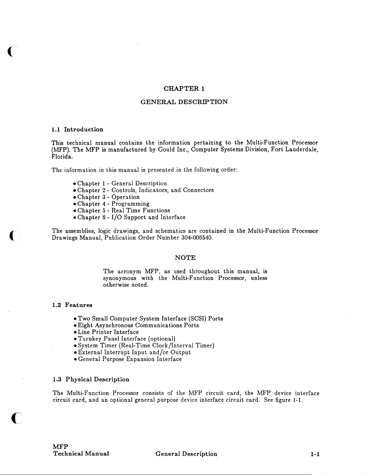
Introduction
This technical manual contains the information pertaining
(MFP).
Florida.
The information
The assemblies, logic drawings, and schematics are contained in the Multi-Function
Drawings Manual, Publication Order Number 304-006540.
The
MFP
•
Chapter
•
Chapter
•
Chapter
•
Chapter
Chapter
•
•
Chapter
is
manufactured
in
this manual
1 - General Description
2 - Controls, Indicators, and Connectors
3 - Operation
4 - Programming
5 - Real Time Functions
6 -
I/O
Support and Interface
by
Gould Inc., Computer Systems Division,
is
presented
DESCRIPTION
in
the following order:
to
the Multi-Function Processor
Fort
Lauderdale,
NOTE
The acronym MFP, as used throughout this manual,
synonymous with the Multi-Function Processor, unless
otherwise noted.
is
Processor
C:
1.2
Features
• Two Small Computer System Interface (SCSI)
• Eight Asynchronous Communications
• Line
• Turnkey Panel Interface (optional)
• System Timer (Real-Time Clock/Interval Timer)
• External
• General Purpose Expansion Interface
1.3
Physical
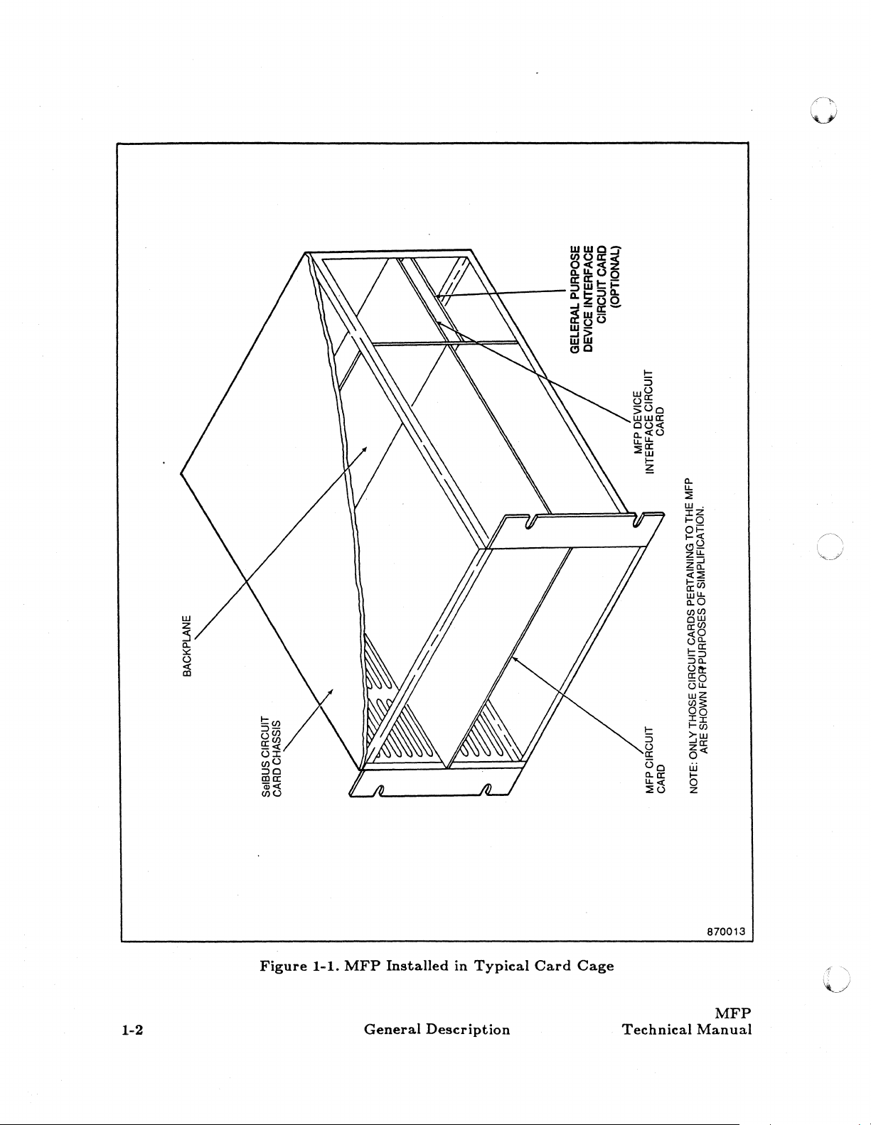
The Multi-Function Processor consists of the MFP circuit card, the MFP device interface
circuit card, and an optional general purpose device interface circuit card.
MFP
Technical
Printer
Interrupt
Description
Manual
Interface
Input
and/or
General
Ports
Output
Description
Ports
See figure
1-1.
1-1
870013
1-2
Figure
1-1.
MFP
General
Installed
Description
in
Typical
Card
Cage
Technical
MFP
Manual
(-
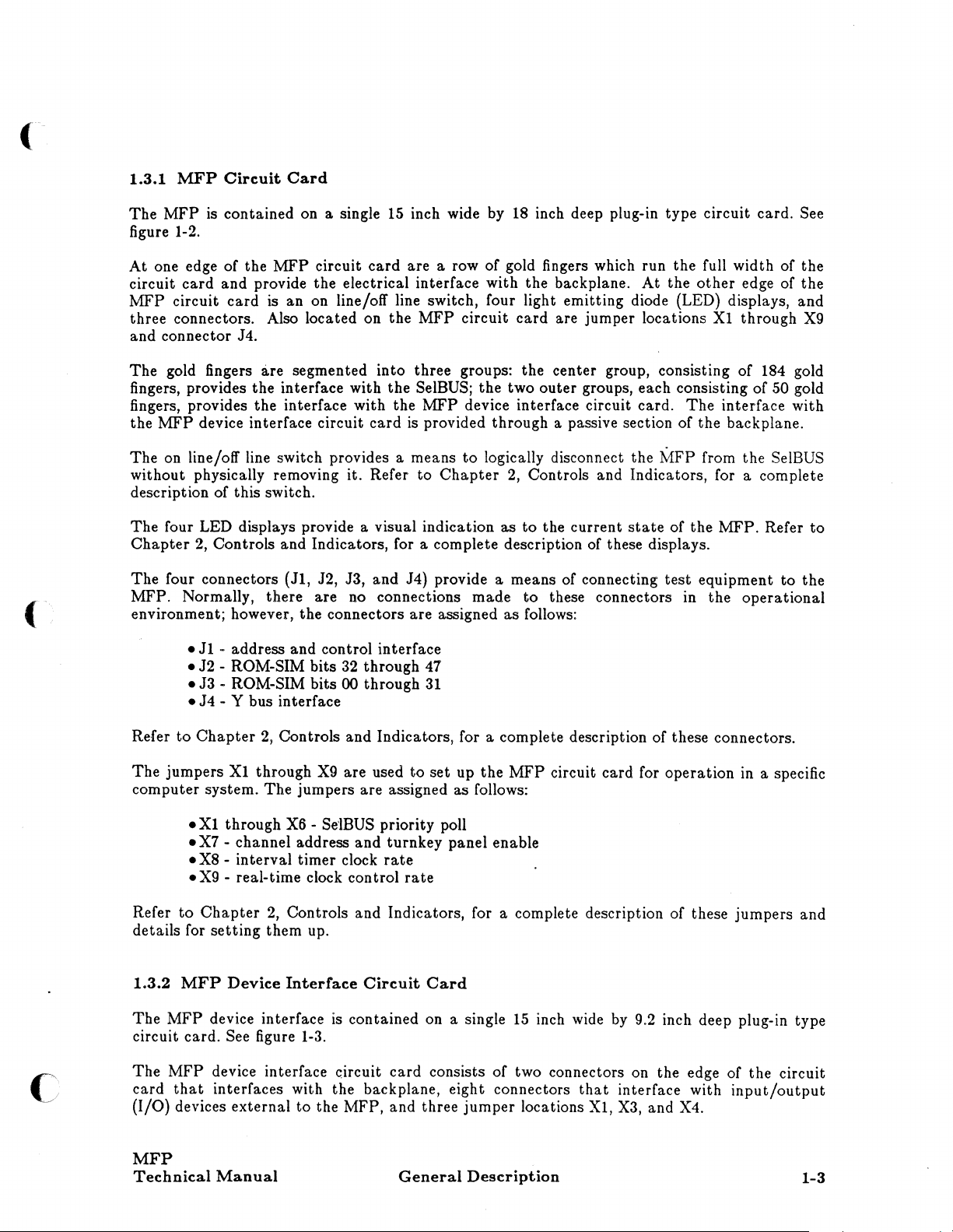
1.3.1
The
figure 1-2.
At
circuit
MFP
three connectors. Also located on the
and connector J4.
The gold fingers
fingers, provides the interface with the
fingers, provides the interface with the
the
The on line/off line switch provides a means
without physically removing it. Refer to
MFP
Circuit
MFP
is contained on a single
one edge of the
card
and provide the electrical interface with the backplane.
circuit
MFP
description of this switch.
The four LED displays provide a visual indication
Chapter
The four connectors
MFP. Normally, there are no connections
environment; however, the connectors are assigned
card
device interface circuit
2, Controls and Indicators, for a complete description of these displays.
Card
15
inch wide by
MFP
circuit
is an on line/off line switch, four light emitting diode (LED) displays, and
a.re
segmented into three groups: the center group, consisting of 184 gold
card
are a row of gold fingers which run the full width of the
MFP
circuit
SelBUS; the two outer groups, each consisting of 50 gold
MFP
device interface circuit card.
card
is
provided through a passive section of the backplane.
to
Chapter
(JI, J2, J3, and J4) provide a means of connecting
made
18
inch deep plug-in type circuit card. See
At
the
other
edge of the
card
are jumper locations
logically disconnect the
2, Controls and Indicators, for a complete
as
to
the current
to
these connectors in the
as
follows:
MFP
state
test
Xl
through
The
interface with
from the SelBUS
of
the
MFP.
equipment
operational
Refer
to
X9
to
the
c
•
Jl
- address and control interface
• J2 - ROM-SIM bits 32 through 47
• J3 - ROM-SIM bits 00 through
• J4 - Y bus interface
Refer
to
Chapter
The
jumpers
computer system. The jumpers are assigned as follows:
•
Xl
• X7 - channel address
• X8 - interval timer clock
•
X9
Refer
to
Chapter
details for
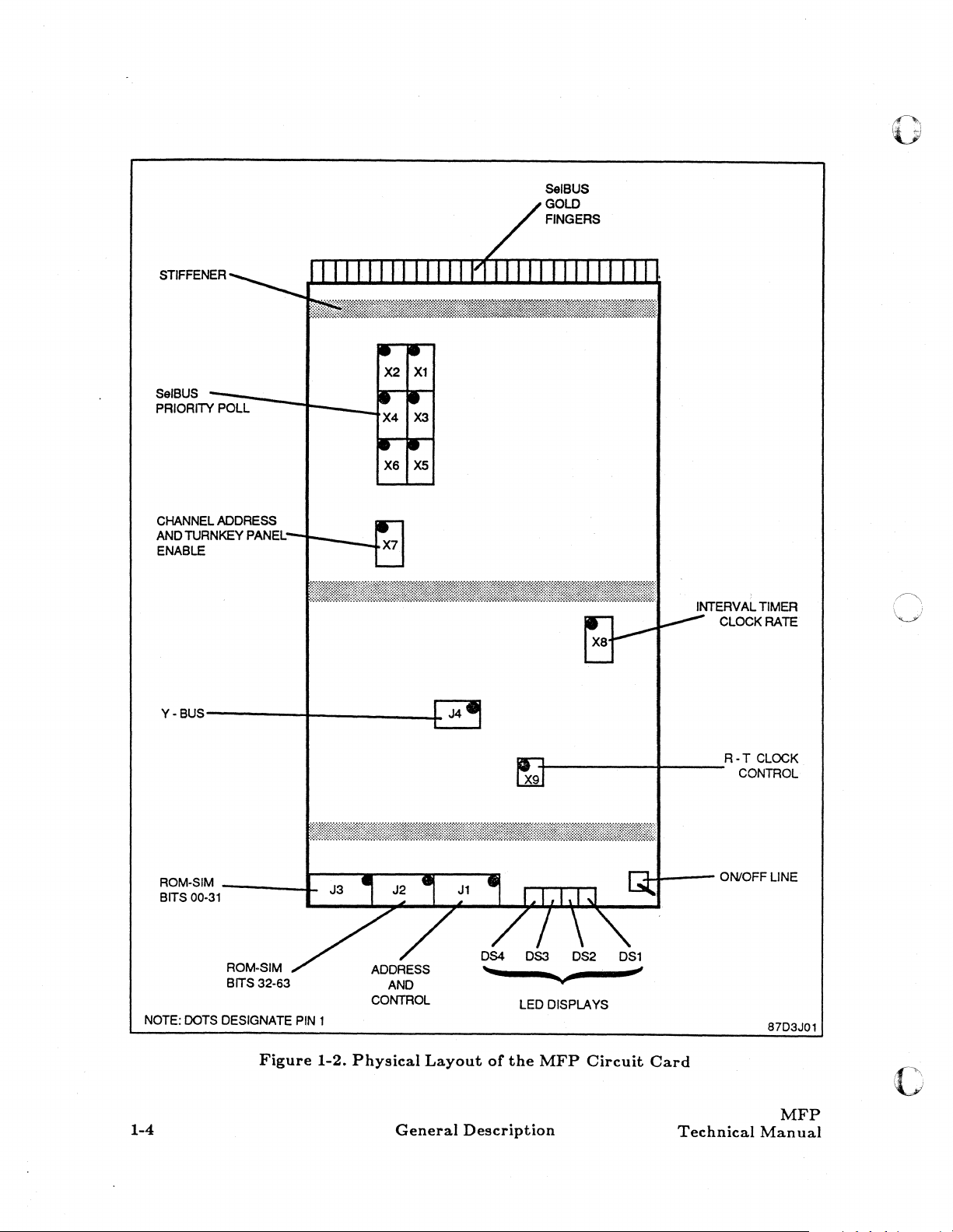
1.3.2
The
circuit card.
The
card
(I/O)
setting
MFP
MFP
device interface
MFP
device interface c.ircuit
that
interfaces with the backplane, eight connectors
devices external
2,
Controls and Indicators, for a complete description of these connectors.
Xl
through
through
- real-time clock control
2,
them up.
Device
See figure 1-3.
X9
are used
X6 -Se'lBUS
and
Controls and Indicators, for a complete description of these jumpers and
Interface
to
the MFP, and three
Circuit
is
contained on a single
31
to
set
up
the
MFP
priority poll
turnkey panel enable
rate
rate
Card
15
card
consists of two connectors on the edge of the circuit
jumper
circuit card for operation
inch wide
locations
by
9.2 inch deep plug-in type
that
interface with
Xl,
X3,
and X4.
in
a specific
input/output
MFP
Technical
Manual
General
Description
1-3
STIFFENER
o
SelBUS
PRIORITY
CHANNELADDAESS
AND
ENABLE
~;U:----I---..J
POLL
TURNKEY
PANEL;
.---Lx7
y-eUS----------+-
__________
-+
+------+----
INTERVAL
CLOCK
R-T
CONTROL
TIMER
RATE
CLOCK
NOTE:
1-4
ROM-SIM
Brrs
00-31
DOTS
_____
ROM-SIM
errs
32-63
DESIGNATE
Figure
-I-
PIN
1
1-2.
Physical
General
Layout
Description
or
LEO
the
DISPLAYS
MFP
Circuit
-i-+---
Card
Technical
ON/OFF
LINE
87D3J01
MFP
Man
c
ual
SCSI
BUS
SCSI
BUSES 1 AND
ADDER
ESSES
1
2
('
ASYNC
PORTS--------~-jr
E4-E7
EXTERNAL
INTERRUPTS
LINE
PRINTER
__
___
+
---'f"
-~"'""'''
TURNKEY
PANEL
LINE
PRINTER
CONTROL
NOTE:
:::::::4--------.-
DOT
DESIGNATES
CONSOLE
BAUD
RATE
PIN
PORT
1
STIFFENER
MFP
Technical
Figure
Manual
1-3.
Physical
Layout
General
of
the
MFP
Description
DI
Circuit
87D3J02
Card
1-5

The two connectors
provide the interface for the
device interface circuit card must occupy the same slot position on the SelBUS circuit
chassis. See figure 1-1.
The eight connectors on the
I/O
devices.
The jumpers
operation in
The
.JI
- SCSI bus 1
• J2 - SCSI bus 2
• J3 - asynchronous ports 0 through 3
• J4 - asynchronous ports 4 through 7
• J5 - external interrupts
• J6 - not used
.J7
- line printer
• J8 - turnkey panel
Xl
a specific computer system configuration.
•
Xl
- SCSI bus address
•
X2
- not used
•
X3
- turnkey panel baud
•
X4
- line printer control
that
interface with the backplane
MFP
circuit card; therefore, the MFP circuit card
outer
edge of the circuit
connectors are labeled
through
X4
are used
rate
are
passive
card
provides the interface with external
J1
through J8 and interface with the following devices:
to
set
up the MFP device interface circuit
The
jumpers are assigned as follows:
to
the backplane, they
and
the
card
MFP
card
for
Refer to
details for setting them up.
1.3.3
The
single
circuit card via the
interface circuit card
card technical manual
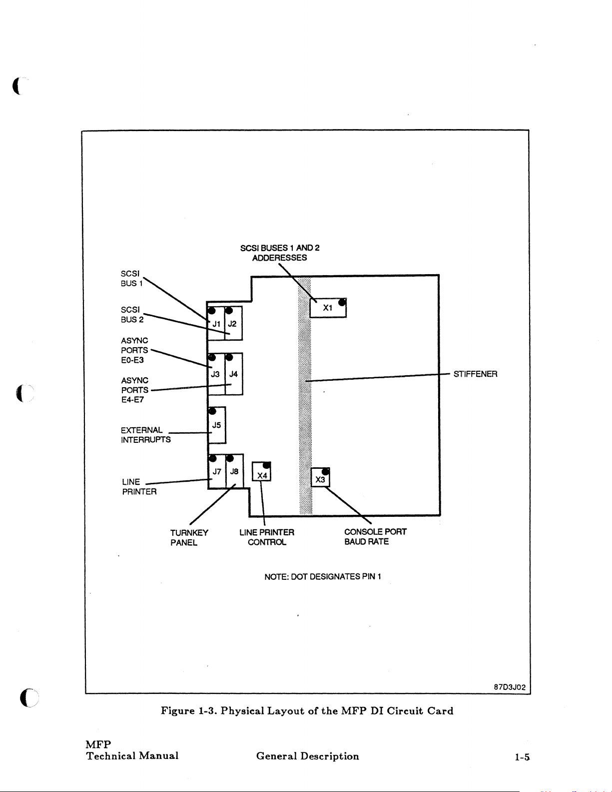
1.4
The
provides two Small Computer System Interface (SCSI) ports, eight asynchronous
communications ports (one port can
parallel printer port, the system timer (Real-Time Clock/Interval Timer), and
interrupts. The
system.
Chapter
Secondary
secondary general purpose device interface is an optional circuit card.
15
inch wide by 9.2 inch deep circuit card.
Functiona.l
MFP
is a single slot, Class
See figure
2,
Controls and Indicators, for a complete description of these jumpers and
General
PIC/PIA
Description
MFP, when combined with a CPU and memory, produces a basic computer
1-4.
Purpose
jumper cards
is
ordered. Refer to the specific general purpose device interface circuit
for
a complete description.
'F'
protocol,
Device
be
utilized
Interface
that
are provided when the general purpose device
I/O
processor, SelBUS interfaced, circuit card.
Circuit
It
connects
by
the optional system console CRT), one
Card
to
the MFP device interface
It
is
contained on a
12 external
It
c
1-6
General
Description
Technical
c
MFP
Manual

c:-
MFP
r
1/0
PANEL
~
..
r
~
7
USER
ASYNC.
PORTS
"
"-v--"
...
SeIBUS
..
MFP
DEVICE
INTERFACE
.~~---.--
_ OPTIONAL '
-
-
-
-
-
,
-
.. ----------------.
GENERAL
PURPOSE
DEVICE
INTERFACE
-.-
110
PORTIS)
~----------------~---------
LINE
PRINTE
R
...
SCSI
BUS
2
...
SCSI
BUS
1
12
EXTERNAL
INTERRUPTS
CONSOLE
CRTAJSER
PORT
(OPTIONAL)
MFP
Technical
Manual
Figure
1-4.
Functional
General
Block
Diagram
Description
with
87D3M03
MFP
1-7
1.4.1
SCSI
Ports
The two Small Computer System Interface (SCSI) ports are used to interface with the SCSI
Bus 1 and the SCSI Bus
as hard disk drives and the
tape units.
than
The
SCSI Bus
only difference between the two buses is
2.
2.
Normally, the SCSI Bus 1
SCSI Bus 2
is
used to interface with
is
used
to
interface with
I/O
devices such
that
SCSI Bus 1 has a higher priority
I/O
devices such
as
magnetic
1.4.2
The asynchronous communications port on the MFP device interface circuit
an
asynchronous communications ports, of the eight ports, one can
CRT
Asynchronous
I/O
panel through a cable
if the
MFP
is
Communications
that
configured
to
Ports
is
provided with the panel.
The
be
run the turnkey panel function.
card
connects with
I/O
panel provides eight
used for the system Console
The
remaining seven
I/O
ports provide RS-232 communications capabilities for the user.
1.4.3
The parallel printer port
Parallel
Printer
Port
is a standard
Data
Products port, it provides the interface for the
line printer.
1.4.4
System
Timer
The system timer port provides the computer system with the real-time clock and interval
timer, as well as the external
1.5
Software
The
MFP
operates with Gould's MPX-32 and UTX/32 operating systems.
interrupt
capabilities.
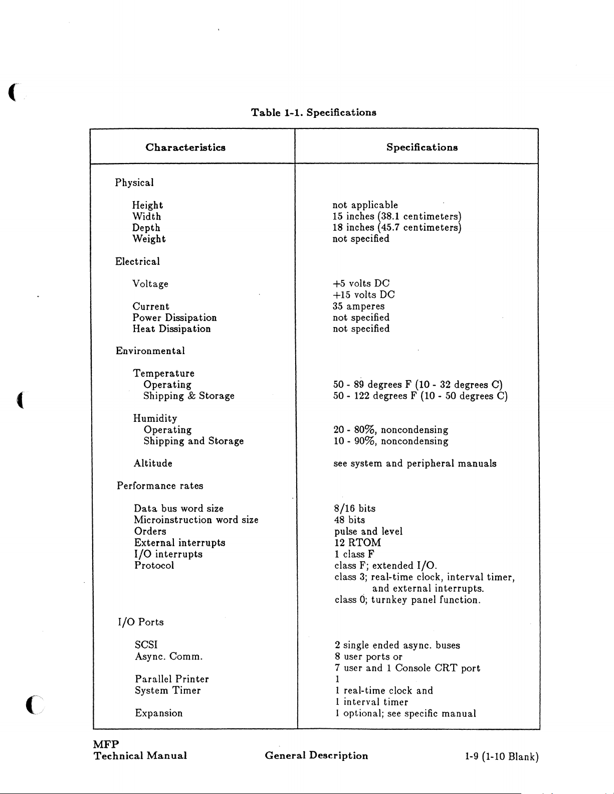
1.6
Specifications
The specifications for the
1-8
MFP
are listed
General
in
Table
Description
1-1.
Technical
MFP
Manual
(
(
Characteristics
Physical
Height
Width
Depth
Weight
Electrical
Voltage
Current
Power Dissipation
Heat
Dissipation
Environmen
Temperature
Humidity
tal
Operating
Shipping &
Operating
Shipping
Storage
and
Storage
Table
1-1.
Specifications
Specifications
not applicable
15 inches (38.1
18
inches (45.7
not specified
+5
volts DC
+15 volts DC
35
amperes
not specified
not specified
50 -
89
degrees F (10 - 32 degrees C)
50 - 122 degrees F (10 - 50 degrees C)
20 - 80%, noncondensing
10 - 90%, noncondensing
centimeters)
centimeters)
(-
Performance
I/O
MFP
Technical
Altitude
rates
Data
bus word size
Microinstruction word size
Orders
External
I/O
Protocol
Ports
SCSI
Async.
Parallel
System
Expansion 1 optional; see specific
Manual
interrupts
interrupts
Comm.
Printer
Timer
General
see system
8/16
48
bits
pulse and level
12
RTOM
1 class F
class F; extended
class
class
2 single ended async. buses
8 user
7 user and 1 Console
1
1 real-time clock and
1 interval
Description
and
peripheral
bits
3;
real-time clock,
and
external
0;
turnkey
ports
or
timer
I/O.
panel function.
manuals
interval
interrupts.
CRT
port
manual
1-9
timer,
(1-10 Blank)

(-.-
.'».\\
"\JI
..
'
(
(
CHAPTER
CONTROLS,
2.1
Introduction
This
chapter
the Multi-Function
card
and
by circuit cards.
2.2
Controls,
The
MFP
limited to controls (on line/off line switch and jumpers), indicators (light emitting diodes
(LED's), and connectors
mentioned components. Each component is described in
chapter.
2.2.1
Controls,
The
controls on
computer system.
switch, and nine
contains the information pertaining
Processor (MFP). The
the
MFP
DI circuit card; therefore, the descriptions in this
Indicators,
circuit
card
and
contains many types
(J connectors). See figure
MFP
sets
Circuit
the
MFP
There
of jumpers.
circuit card enable the user
are two types of controls on the
INDICATORS,
MFP
Connectors,
Card
2
and
CONNECTORS
to
the controls, indicators, and connectors of
consists of
MFP
Circuit
of
components; however, this
2-1
two
circuit cards: the
Card
for
the
detail
to
configure the
MFP
circuit card:
chapter
actual
as you progress through this
are broken down
chapter
location of the above
MFP
for a specific
the
on line/off line
MFP
circuit
will
be
2.2.1.1
The
SelBUS. When the switch is placed
receivers, resident
in
initiation of new actions will not take place. When
will not be illuminated,
however, the
as if on line.
The on line/off line switch of the
up; however,
taking place will
configured with a
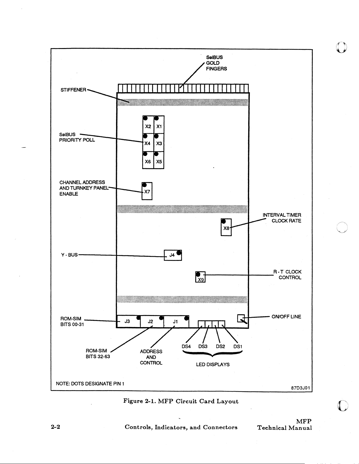
2.2.1.2
The
header.
well as, the logic drawings and the
On
Line/Off
on line/off line switch provides the means
a "hold"
state.
other
it
Jumpers,
MFP
circuit card contains nine sets of jumpers. Each
The
jumper
Line
Switch,
to
the
MFP, are disabled. When the
With
the firmware in a hold
thus
indicating
LED's,
is
recommended
be
turnkey
MFP
OS1
through OS3, will remain operational and indicate there
MFP
that
completed before the
panel,
Circuit
headers are labeled from
it
Card
MFP
Circuit
in
the
that
can
the system be halted so
status
will not function if the
actual
MFP
off
the
be
changed while the
Xl
circuit card.
MFP
TechnicaIManual
Controls,
Indicators,
Card
to
logically disconnect the
line position, all of the SelBUS drivers and
MFP
is
disabled,
state,
the
MFP
of
the
through
and
micro
MFP
is
interrupts
is
off
in
an
off
that
MFP
is
changed. Note: if the
MFP
is
set
of jumpers makes up one
X9
and called
Connectors
are serviced; however,
line, the LED indicator, OS4,
line (non-operational)
computer
any SelBUS transactions
off line.
its
firmware
system
out
MFP
from the
is
is
powered
MFP
jumper
in
figure 2-1, as
placed
state;
status
2-1
is
STIFFENER
["
V
SeIBUS
GOLD
FINGERS
SelBUS
PRIORITY POLL
CHANNEL ADDRESS
AND TURNKEY PANEl:
ENABLE
Y·BU~)---------~--
-;;;-;----1-___ I
________
~
R·T
4-----------~------
CLOCK
CONTROL
ROM-SIM
BITS 00-31
NOTE: DOTS DESIGNATE
---_..I-
ROM·SIM
BITS 32·63
2-2
PIN
1
Figure
2-1.
Controls,
MFP
Circuit
Indicators,
LED
Card
and
Connectors
DISPLAYS
Layout
-'-11----
ON/OFF LINE
Technical
87D3JOl
c
MFP
Manual
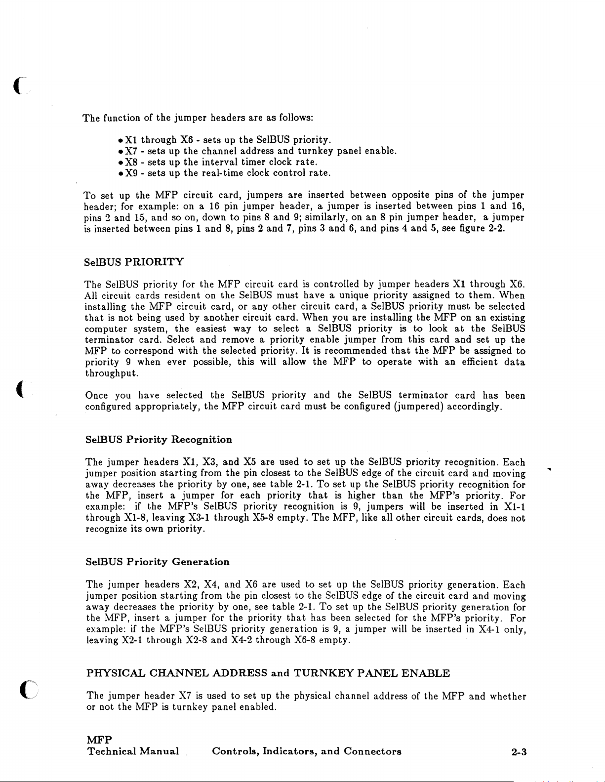
The
function of the
.Xl
through X6 -
•
X7 -sets
•
X8 -sets
•
X9 -sets
To
set
up the
header; for example: on a
pins
2 and 15, and so on, down
is
inserted between pins 1 and
jumper
up the channel address and
up the interval timer clock
up the real-time clock control
MFP
circuit card, jumpers are inserted between opposite pins of the
headers are
sets
up the SelBUS priority.
16
pin jumper header, a jumper
to
8,
pins 2 and 7, pins 3
pins 8
as
follows:
and
turnkey
rate.
rate.
9;
similarly, on an 8 pin jumper header, a
panel enable.
is
and
6,
and pins 4 and 5, see figure 2-2.
jumper
inserted between pins 1 and 16,
jumper
(
SelBUS
The SelBUS priority for the
All
installing the
that
computer system, the easiest way
terminator
MFP
priority 9 when ever possible, this will allow the
throughput.
Once you have selected the
configured appropriately, the
SelBUS
The jumper headers
jumper position
away decreases the priority by one, see table 2-1.
the
example: if the
through XI-8, leaving
recognize its own priority.
PRIORITY
MFP
circuit card
circuit cards resident on the SelBUS must have a unique priority assigned
MFP
circuit card,
is
not being used by
card. Select
to
correspond with the selected priority.
Priority
MFP, insert a
Recognition
starting
MFP's
another
and
Xl,
X3,
from the pin closest
jumper
SelBUS priority recognition
Xl-I
or
any
other
circuit card. When you are installing the
to
remove a priority enable jumper from this
SelBUS priority and the SelBUS
MFP
circuit
and
X5
are used
for each priority
through X5-8 empty.
is
controlled by
circuit card, a SelBUS priority must be selected
select a SelBUS priority
It
is
recommended
MFP
card
must be configured (jumpered) accordingly.
to
set
up the SelBUS priority recognition. Each
to
the SelBUS edge of the circuit
To
set
that
is
higher
is
The
MFP, like all
jumper
is
that
to
operate
terminator
up the SelBUS priority recognition for
than
9,
jumpers will be inserted
other
headers
to
the
with
the
circuit cards, does not
MFP
look
card
MFP
an
card
MFP's
Xl
through X6.
to
them. When
on
an
existing
at
the SelBUS
and
set
be assigned
efficient
card
has been
and moving
priority. For
in
up the
to
data
Xl-l
c
SelBUS
The jumper headers X2, X4, and
jumper position
away decreases the priority by one, see table 2-1.
the
example: if the
leaving
PHYSICAL
The jumper header
or not the
Priority
starting
MFP, insert a
MFP's
X2-1
through X2-8
CHANNEL
MFP
is
Generation
X6
are used
from the pin closest
jumper
for the priority
SelBUS priority generation
and
X4-2 through X6-8 empty.
ADDRESS
X7
is
used
to
set up the physical channel address of the
turnkey panel enabled.
to
that
and
TURNKEY
to
the SelBUS edge of the circuit
MFP
Technical
Manual
Controls,
Indicators,
set
up the SelBUS priority generation. Each
card
To
set up the SelBUS priority generation for
has been selected for the
is
9,
a jumper will
and
Connectors
PANEL
ENABLE
be
inserted
MFP's
MFP
priority.
in
and whether
and moving
For
X4-1 only,
2-3
o
16PIN
'X'
HEADER
16 15 14 13
•••••
r.
1
NOTE:
SIDE
•
2
PIN 1 IS
OF
THE
•
• •
3 4
LOCATED
HEADER
11
12
•
• • •
5
6 7 S
ON
CLOSEST
10 9 S
••
•••
r.
1
BOTH
MFP
AND
TO
THE
SeIBUS.
7
•
2 3 4
MFP
01
6 5
•
AT
•
SPIN
'X'HEADER
•
THE
2-4
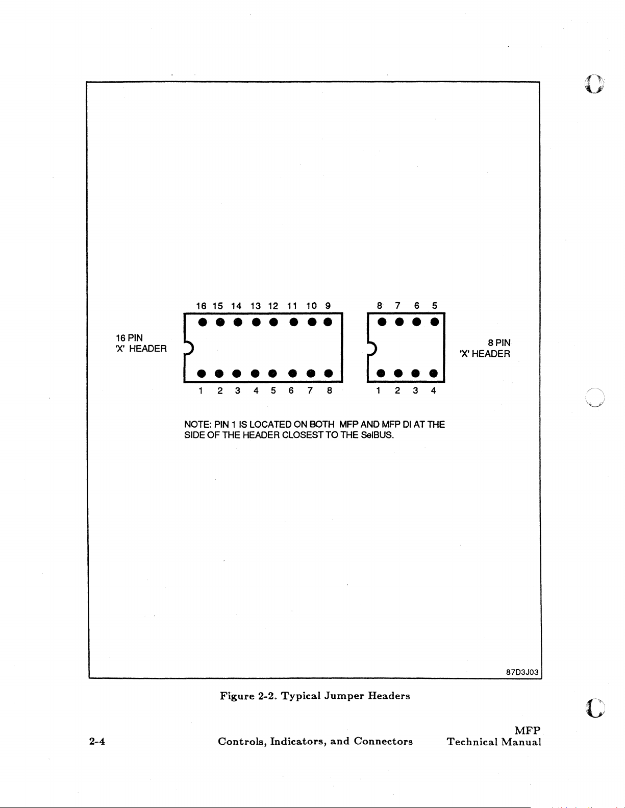
Figure
Controls,
2-2.
Typical
Indicators,
Jumper
and
Headers
Connectors
Technical
87D3J03
o
MFP
Manual

Table
2-1.
SelBUS
Priority
Jumpers
(
SelBUS
Recognition
XI-2
XI-3
XI-4
XI-5
Xl-6
XI-7
XI-8
X3-1
X3-2
X3-3
X3-4
X3-5
X3-6
X3-7 X4-6 14
X3-8
X5-1
X5-2 X6-1 17
X5-3 X6-2
X5-4 X6-3
X5-5 X6-4
X5-6 X6-5
X5-7 X6-6 22
X5-8 X6-7 not used
Priority
SelBUS
Generation
X2-1 1
X2-2 2
X2-3 3
X2-4 4
X2-5 5
X2-6 6
X2-7 7
X2-8 8
X4-1
X4-2
X4-3
X4-4
X4-5
X4-7
X4-8
X6-8
Priority
SelBUS
Level
not used
Priority
9
10
11
12
13
15
16
18
19
20
21
Physical
The
X7-5).
channel address of the
physical channel address.
When
limited
By
using those class "F" channel addresses,
than
class "F" software commands directed
software commands directed
Channel
physical channel
Jumpers
setting
to
one of the following: 06,
the class "F" channel address.
Address
X7-2
The
addresses
on X7.
up the
address
through
MFP,
CPU
scratch
to
MFP's
is
X7-5 determine
with
the physical channel address
physical channel address, valid class "F" channel addresses are
to
the odd physical channel address 47.
set
up
jumper
pad
OE,
For
MFP
Technical
Manual
Controls,
at
jumper
X7-2 determining the most significant
NOTE
is
used
16,
IE,
the
RTF
example:
to
the even physical channel address 46,
Indicators,
header X7, pins 2 through 5 (X7-2 through
the
most significant four
to
map
the logical channel
that
is
jumpered
26, 2E, 36, 3E, 46, 4E, 56, 5E,
address will always be one
an
MFP
with X7-2 jumpered will respond
and
Connectors
bits
of
66,
6E, 76,
greater
the
bit
and
physical
of the
or
7E.
(higher)
to
RTF
2-5
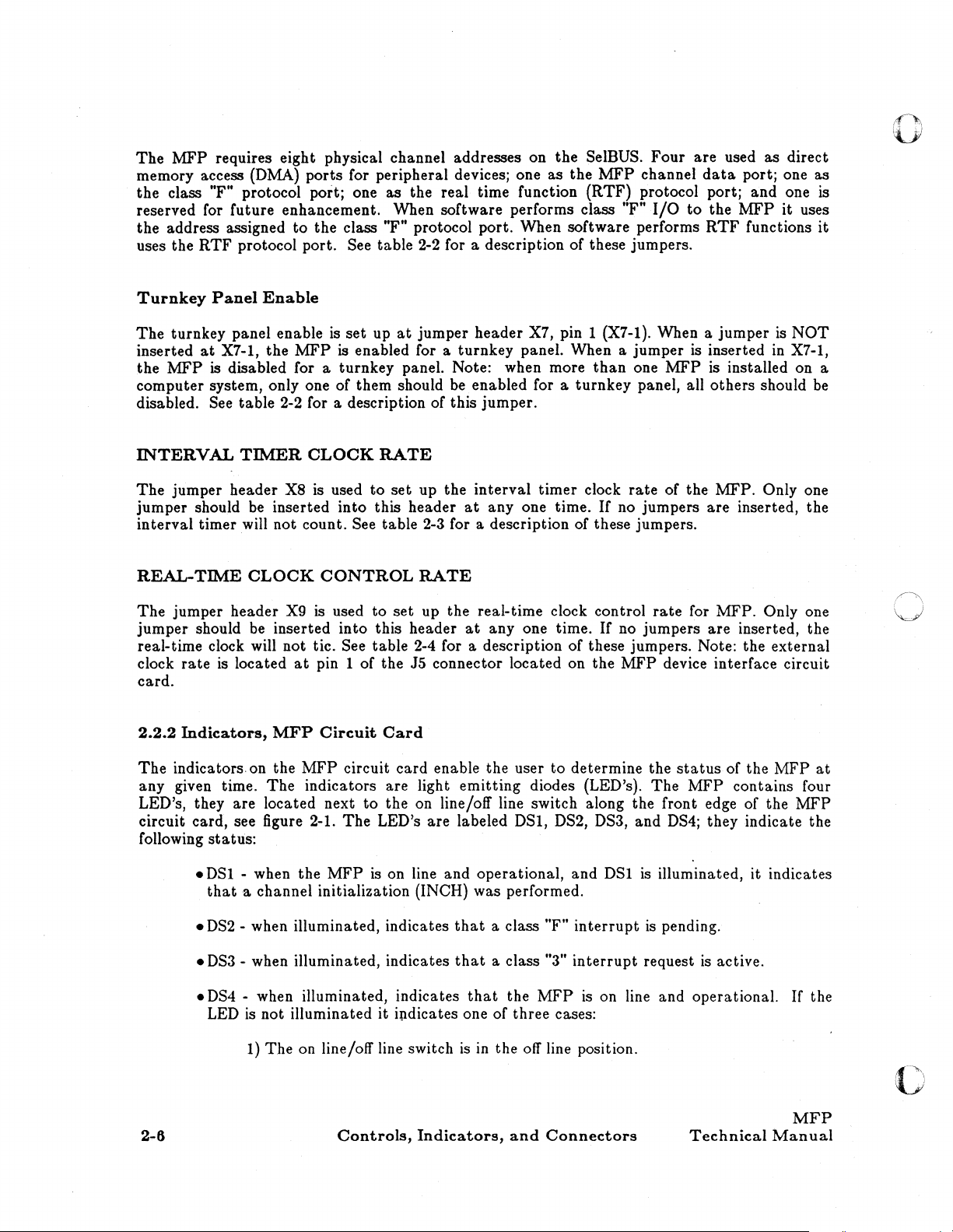
The
MFP
requires eight physical channel addresses on the SelBUS.
memory access (DMA)
the
class "F" protocol port; one as the real time function (RTF) protocol port; and one is
ports
for peripheral devices; one as the
MFP
reserved for future enhancement. When software performs class
the
address assigned to the class "F" protocol port. When software performs
uses the
RTF
protocol port. See table 2-2 for a description of these jumpers.
channel
"F"
Four
I/O
are used
data
to
the
RTF
porti one as
MFP
functions
as
direct
it
uses
:1-""'.
'lJ!
it
Turnkey
The
inserted
the
computer system, only one of them should
Panel
Enable
turnkey panel enable is
at
MFP
X7-1, the
is
disabled for a turnkey panel. Note: when more
MFP
set
up
at
jumper header X7, pin 1 (X7-1). When a
is enabled for a turnkey panel. When a
be
enabled for a
disabled. See table 2-2 for a description of this jumper.
INTERVAL
The
jumper header X8 is used
jumper should
interval
REAL-TIME
The
jumper header
jumper
real-time clock will not tic.
clock
rate
TIMER
be
CLOCK
inserted
to
into
RATE
set
up the
this header
interval
at
anyone
timer will not count. See table 2-3 for a description of these jumpers.
should
is located
CLOCK
be
CONTROL
X9
is used
to
RATE
set
up the real-time clock control
inserted into this header
See
table
2-4 for a description
at
pin 1
of
the J5 connector located on the
at
anyone
card.
2.2.2
Indicators,
MFP
Circuit
Card
timer
time.
time.
of
jumper
jumper
than
one
turnkey
clock
panel, all
rate
If
no jumpers
If
no jumpers are inserted, the
is inserted
MFP
is installed on a
others
of the MFP. Only one
are
rate
for MFP. Only one
is
NOT
in
X7-1,
should
inserted, the
these jumpers. Note: the external
MFP
device interface circuit
be
The
indicators on the
any given time.
MFP
circuit
The
indicators are light
LED's, they are located next
circuit card, see figure 2-1.
following
status:
• DSI - when the
that
a channel initialization (INCH) was performed.
•
DS2
- when illuminated, indicates
•
DS3
- when illuminated, indicates
•
DS4
- when illuminated, indicates
The
MFP
LED is not illuminated
1)
The
on line/off line switch
Controls,
card
enable the user to determine the
emitting
to
the on line/off line switch along the front edge of the
LED's are labeled
is
on line and operational, and DSI
that
that
that
it
ipdicates one of three cases:
is
in
Indicators,
diodes (LED's).
DSl,
DS2, DS3, and
a class "F"
a class "3"
the
MFP
the
off
line position.
and
Connectors
interrupt
interrupt
is
on line and operational.
status
The
DS4;
is
illuminated, it indicates
is
pending.
request
of the
MFP
contains four
they indicate the
is
active.
Technical
MFP
at
MFP
If
the
MFP
Manual
'.f.· . ""
.... " ..
~"
 Loading...