

Page 1

User Guide
CAUTION: Federal (USA) law restricts this device to sale by or on the order of a physician.
Page 2

-2-
RIGISCAN
®
(User Guide)
©2016 GOTOP Medical
This manual pertains only to the GOTOP Medical RigiScan® Plus System. All rights reserved. Printed in the
U.S.A. U.S. Patent Nos. 4,515,166 and 4,766,909 apply.
Le présent manuel ne s’applique qu’au système RigiScan® Plus d’’GOTOP Medical . Tous droits réservés. Imprimé aux Etats- Unis d’Amérique. Les brevets U.S. n° 4,515,166 et 4,766,909 sont applicables.
Dieses Handbuch behandelt ausschließlich das GOTOP Medical RigiScan® Plus Rigidity Assessment System.
Alle Rechte vorbehalten. Gedruckt in den U.S.A. U.S. Patent Nr. 4,515,166 und 4,766,909 kommen zur
Anwendung.
Questo manuale riguarda soltanto il sistema di valutazione della rigidità RigiScan® Plus della GOTOP Medical.
Tutti i diritti sono riservati. Stampato negli USA. Sono validi i brevetti statunitensi No. 4, 515, 166 e 4,766,909.
Este manual concierne sólo al Sistema de Evaluación de Rigidez RigiScan® Plus de GOTOP Medical . Se
reservan todos los derechos. Impreso en los Estados Unidos. Se aplican las patentes estadounidenses núm.
4,515,166 y 4,766,909.
Deze handleiding heeft alleen betrekking op het GOTOP Medical RigiScan® Plus-systeem voor evaluatie van
stijfheid. Alle rechten voorbehouden. Gedrukt in de V.S. Octrooinummers (V.S.) 4,515,166 en 4,766,909 zijn
van toepassing.
Este manual refere-se apenas ao Sistema de Avaliação de Rigidez RigiScan® Plus da GOTOP Medical . Todos
os direitos reservados. Coberto pelas Patentes Nos. 4.515.166 e 4.766.909 dos E.U.A.
Page 3

-3-
Table of Contents
Chapter 1: Introduction . . . . . . . . . . . . . . . . . . . . . . . . . . . . . . . . . . . . . . . . . . . . . . . . . . . . . . . . . . . . . . . . .5
1.1 Contraindications, Warnings, Cautions, and Side Effects . . . . . . . . . . . . . . . . . . . . . . . . . . . . . . . .5
1.2 Principles of Operation .... ... .. .. ... .. .. ... .. .. ... .. .. ... .. .. ..... .. ..... .. ....7
1.3 The RigiScan Plus Monitoring System ...............................................8
Chapter 2: Setting Up the RigiScan Plus System . . . ..... . . . . . . . . . . . . . ..... . . . . . . . . . . . . . ..... . .9
2.1 System Requirements . . . . . . . . . . . . . . . . . . . . . . . . . . . . . . . . . . . . . . . . . . . . . . . . . . . . . . . . . .9
2.2 Setting Up the Hardware ........................................................9
2.3 Connecting the Event Marker (Optional) ...........................................10
2.4 Installing the RigiScan Plus Software ..............................................11
Chapter 3: Software Operation...........................................................13
3.1 Starting RigiScan Plus..........................................................13
3.2 The RigiScan Plus Home Screen..................................................14
3.3 RigiScan Control Window ... ........ ... ..... ... ........ ... ........ ... ........ ..15
Initializing the Monitor.........................................................16
3.4 Patient Management Window ...................................................18
3.5 Report Manager Window . . . . . . . . . . . . . . . . . . . . . . . . . . . . . . . . . . . . . . . . . . . . . . . . . . . . . .25
Filtering Available Patients ......................................................26
Report Selector ..............................................................27
3.6 Data Management Window .. .. .. ..... .. .. .. ..... .. .. ..... .. .. .. ..... .. .. .. ....28
3.7 RigiScan Settings Window . . . . . . . . . . . . . . . . . . . . . . . . . . . . . . . . . . . . . . . . . . . . . . . . . . . . . .33
General Tab .. ..... ....... ..... .. ..... .. ..... ..... .. ..... .. ..... ....... .....33
Rx Codes Tab . . . . . . . . . . . . . . . . . . . . . . . . . . . . . . . . . . . . . . . . . . . . . . . . . . . . . . . . . . . . . . .36
Drug Codes Tab . . . . . . . . . . . . . . . . . . . . . . . . . . . . . . . . . . . . . . . . . . . . . . . . . . . . . . . . . . . . .37
Prosthesis Codes Tab ..........................................................38
About Tab . . . . . . . . . . . . . . . . . . . . . . . . . . . . . . . . . . . . . . . . . . . . . . . . . . . . . . . . . . . . . . . . . .39
Chapter 4: Preparing the RigiScan Plus System for Patient Testing .............................. 40
4.1 Installing the Tension Guides ................................................... 40
4.2 Removing the Tension Guides .................................................. 41
4.3 Installing the Loop Covers ..................................................... 42
4.4 Removing the Loop Covers .................................................... 43
4.5 Installing the Batteries ........................................................ 43
4.6 Attaching the Leg Strap ....................................................... 44
Chapter 5: Patient Testing .. .. .. .. .. .. .. .. .. .. .. .. .. .. .. .. .. .. .. .. .. .. .. .. .. .. .. .. .. .. .. .45
5.1 Nocturnal and Provocative Collection Modes .......................................45
Nocturnal Testing.............................................................45
Provocative Testing ...........................................................45
5.2 Instructing the Patient .........................................................46
Removing the Loops Quickly ....................................................46
5.3 Testing Patients Using the Real-time and Ambulatory Modes ....... ... ........ ... .......47
Real-time Testing . . . . . . . . . . . . . . . . . . . . . . . . . . . . . . . . . . . . . . . . . . . . . . . . . . . . . . . . . . . . .47
Ambulatory Testing ....... .. .. .. ....... .. .. .. .. ....... .. .. .. ....... .. .. .. .. ...48
Page 4

-4-
RIGISCAN
®
(User Guide)
Table of Contents (continued)
Beep Cues .... .. ..... .. ....... .. ..... .. ..... .. ....... ....... .. ..... .. ..... .. .50
5.4 The Characterization Session . . . . . . . . . . . . . . . . . . . . . . . . . . . . . . . . . . . . . . . . . . . . . . . . . . . .50
5.5 Downloading Data from the Monitor..............................................50
Chapter 6: RigiScan Plus Reports..........................................................51
6.1 The Session Scan Summary Report................................................51
6.2 The Summary Analysis Statistic Report .............................................52
6.3 Printing Session Scan Summary and Summary Analysis Statistics Reports...................53
6.4 Patient Summary Report . . . . . . . . . . . . . . . . . . . . . . . . . . . . . . . . . . . . . . . . . . . . . . . . . . . . . . .53
6.5 Treatment Summary Report . . . . . . . . . . . . . . . . . . . . . . . . . . . . . . . . . . . . . . . . . . . . . . . . . . . . .54
6.6 General Session Info Report . . . . . . . . . . . . . . . . . . . . . . . . . . . . . . . . . . . . . . . . . . . . . . . . . . . .54
6.7 Base Data Report . . . . . . . . . . . . . . . . . . . . . . . . . . . . . . . . . . . . . . . . . . . . . . . . . . . . . . . . . . . .55
6.8 Tip Data Report ..............................................................55
Chapter 7: Maintenance ................................................................56
7.1 Maintenance ................................................................56
Glossary . . . . . . . . . . . . . . . . . . . . . . . . . . . . . . . . . . . . . . . . . . . . . . . . . . . . . . . . . . . . . . . . . . . . . . . . . .57
Appendix A: Product Specications Physical Dimensions .......................................60
Appendix B: Patient Instructions ..........................................................61
Appendix C: References ................................................................65
Appendix D: Electromagnetic Declaration ... . . ... . . ... . . ... . . . ... . . ... . . ... . . ... . . . ... . . ...66
Appendix E: RigiScan Nomogram .........................................................70
Appendix F: Limited Warranty ............................................................71
Page 5
-5-
Contraindications
• Not for use in evaluating erectile capability in children.
• Do not use the RigiScan Plus Monitor in men who have communicable skin or venereal diseases or men who have any rash or lesions on the penis or surrounding area.
• Do not use in men with impaired mental capacity unless the testing period is directly supervised by appropriate medical personnel.
Chapter 1: Introduction
The RigiScan Plus System allows you to measure the duration, frequency, and degree of rigidity and
tumescence of the penis. This device provides a graphical and tabular display of base and tip penile
rigidity and tumescence data for the physician’s interpretation. The design of the RigiScan Plus System
makes it simple for you and your patients to use, yet it offers a sophisticated range of capabilities and
applications. The system is suitable for nocturnal data collection or data collection during various
provocative interventions that are intended to produce an erectile response. Testing may be conducted in a stand-alone Ambulatory mode or in a Real-time monitoring mode when connected to your
computer.
This chapter contains important information which must be observed to ensure patient safety and
proper operation of the RigiScan Plus system.
Warnings
Adequate patient education is required to assure safe operation of the RigiScan Plus by a patient for
in-home nocturnal testing.
• DO NOT use the RigiScan Plus Monitor if the tension guide boots are loose, the cable is
kinked or curled, or the tension guide is crushed or broken. Use of worn or damaged tension
guides may result in patient injury.
• DO NOT use the RigiScan Plus Monitor with improperly or incompletely installed tension
guides. The tension guides must be inserted in the monitor with the tension guide pin fully
seated in the slot on the top of the housing. Use of a RigiScan Plus with improperly inserted
tension guides may result in patient injury.
• DO NOT operate the RigiScan Plus Monitor near sources of intense pulsed or conducted
electrical or magnetic elds such as Magnetic Resonance Imaging (MRI), CT scan, X-ray,
Page 6
-6-
RIGISCAN
®
(User Guide)
electrocautery, electrocoagulation, diametry or telemetry equipment, high power transmitters, or household appliances such as electric blankets, electric razors, power tools, micro-
wave ovens, hair dryers or cellular phones. Items such as these may interfere with operation
of the monitor and cause erroneous readings.
• Patients MUST NOT bath or shower while wearing the RigiScan Plus Monitor. Getting the
monitor wet may cause electrical shock to the patient or damage to the monitor.
• Patients MUST NOT engage in any sexual activity, such as intercourse, oral sex or masturbation, during RigiScan Plus testing. Doing so may result in patient injury or erroneous data.
• Patients with impaired penile sensation are at greater risk of exposure to maximum compressive forces should the system fail to operate properly.
• DO NOT turn the RigiScan Plus Monitor “on” until the loops have been placed on the penis.
Turning the monitor on before placing the loops will cause continuous rigidity sampling and
may result in patient discomfort, pain, irritation or bruising.
• The RigiScan Monitor must be turned “off” prior to urination. The monitor may be turned
off for a continuous period of up to 15 minutes without interrupting the monitoring session.
Urinating with the monitor on may cause pain, urethral irritation or hematuria.
• The RigiScan Monitor must be turned “off” prior to readjusting the position of the loops on
the penis. Adjusting the loops with the monitor on may cause continuous rigidity sampling
and result in patient discomfort, pain, irritation or bruising.
• Reuse of disposable loop covers may result in patient injury or transmission of communicable disease.
• When the RigiScan Plus System is to be used in a Real-time Monitoring Mode (RTM), the host
PC must use an isolation transformer manufactured to EN60601 standards. Failure to do so
may result in a safety hazard.
Cautions
• Ingestion of coffee, tea, cola, alcoholic beverages, sedatives, tranquilizers, muscle relaxants
or sleeping pills in the period immediately preceding nocturnal testing with the RigiScan Plus
may affect test results by interfering with normal sleep patterns.
Warnings (continued)
Page 7
-7-
• Care must be taken to remove the tension guides slowly and gently to avoid damage to the
cables or internal mechanisms. Removing the tension guides too quickly may damage the
monitor or result in an “out-of-phase” condition and inability to re-insert the tension guides.
• USE ONLY the communications cable supplied with the RigiScan Plus system. Alternate
communications cables are not compatible with the system and may damage the RigiScan
Plus Monitor.
• USE ONLY Duracell 9-volt disposable alkaline or GOTOP approved rechargeable 9-volt bat-
teries. Other batteries may not have sufcient power to complete a Monitoring session.
• Federal (USA) law restricts this device to the sale or use by or on the order of a physician.
Side Effects and Complications
The side effects and complications listed below have been reported with use of the device:
• Penile pain, redness, bruising, abrasion or cuts of the penile skin from action of the loops
• Urethral bleeding
• Hematuria
1.2 Principles of Operation
The RigiScan Plus Monitor is an ambulatory data logging unit that measures and records penile rigidity
and tumescence. It is linked by cable to an IBM-compatible computer, which downloads and processes the data, stores it for review, and prints it on command. The ambulatory monitor uses tip and base
penile loops that adjust by tightening slightly at discrete time intervals to measure and record penile
rigidity and tumescence. Each loop contains a cable that moves freely inside a conduit. Each loop
takes a measurement every 15 seconds. The loop gently tightens with a linear force of 4 ounces (114g)
and then immediately releases and the tissue rebounds to its unloaded state. The RigiScan Plus Monitor
then takes a tumescence measurement. After the tumescence measurement is taken, it is compared to
the previous samples. When a 6 mm increase in tumescence is detected, representing possible erectile
activity, the RigiScan Plus Monitor takes a second measurement every 30 seconds. After tumescence
is measured, the loops tighten a second time around the circumference of the penis with a linear force
of 10 ounces (283.5g). The RigiScan Plus Monitor takes a measurement when this force is applied to
record a cross sectional response to radial compression. This is how rigidity is measured.
Page 8

-8-
1.3 The RigiScan Plus Monitoring System
The RigiScan Plus System consists of the following components and accessories:
• RigiScan Plus Monitor
• RigiScan Plus Program (USB)
• Carrying case
• Box of Leg straps
• Communications cable
• Event Marker cable (optional)
• RigiScan Plus User’s Manual
• Set of tension guides
• Box of loop covers
• Box of Duracell 9-volt Batteries
Optional Accessories:
• Rechargeable Batteries and Charger are available for purchase from GOTOP Medical Inc.
NOTE: Excluding the customer provided EN60950 compliant PC, all components of the RigiS-
can system are suitable for use in the patient environment.
RIGISCAN
®
(User Guide)
Fig. 1-1
Page 9
-9-
Chapter 2: Setting Up the RigiScan Plus System
2.1 System Requirements
Before you can install the RigiScan Plus Software, you must assemble the following hardware com-
ponents:
• EN 60950 Compliant IBM-compatible personal computer (PC) equipped with:
• Microsoft Windows XP Service Pack 3 or newer (Windows 7, 8, 8.1, and 10)
• Hard-disk with at least 1 GB of free disk space
• At least 1 GB of random-access memory (RAM)
• Available USB 2.0 port
• VGA compatible graphics card
• VGA monitor
• Mouse and keyboard
• Printer
• Supplied USB Flash Drive
Note: Windows DPI setting should be 100% for optimum display. “Unsupported DPI” warning may
appear at launch when using other DPI setting.
2.2 Setting Up the Hardware
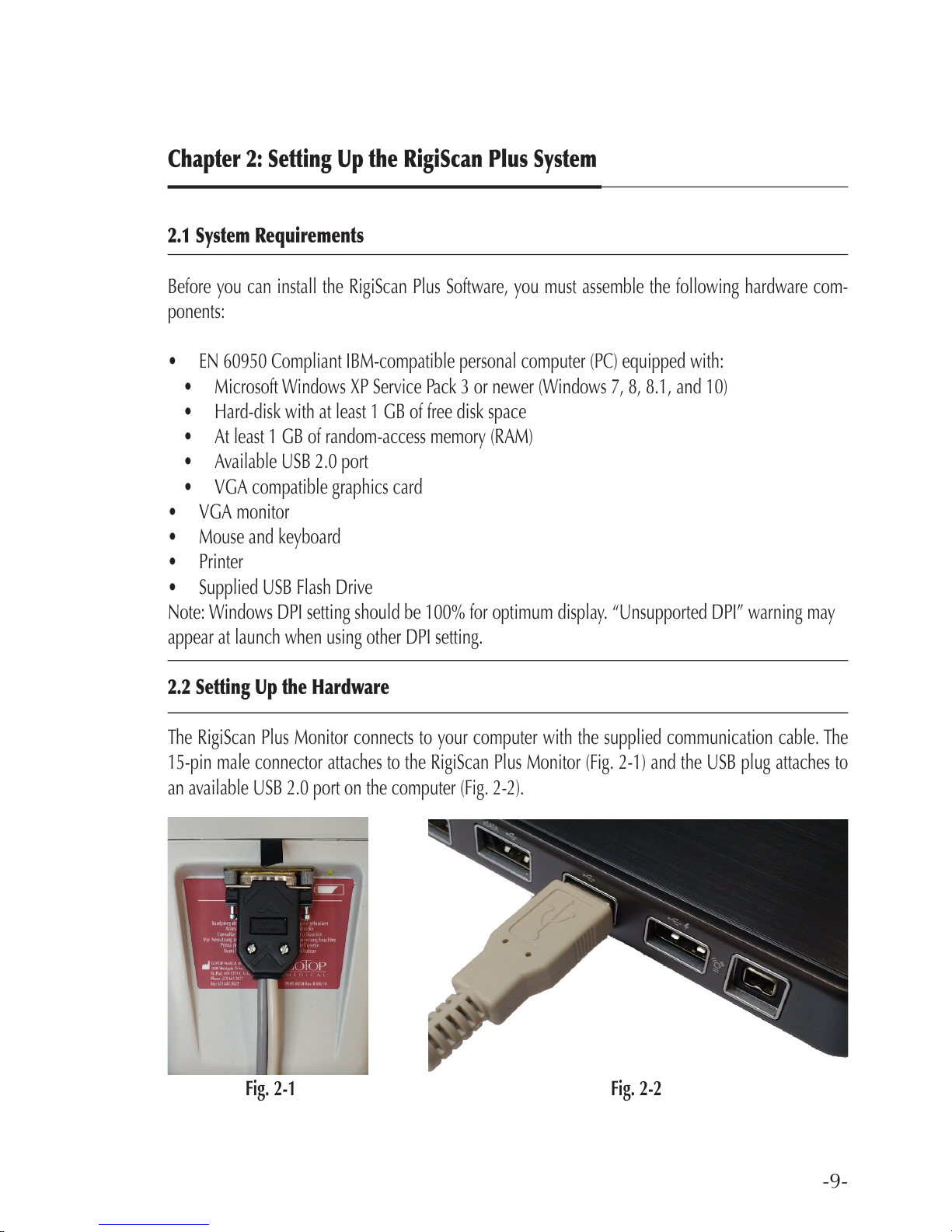
The RigiScan Plus Monitor connects to your computer with the supplied communication cable. The
15-pin male connector attaches to the RigiScan Plus Monitor (Fig. 2-1) and the USB plug attaches to
an available USB 2.0 port on the computer (Fig. 2-2).
Fig. 2-1 Fig. 2-2
Page 10
-10-
RIGISCAN
®
(User Guide)
2.3 Connecting the Event Marker (Optional)
You can use the optional Event Marker to mark pertinent points in the patient data.
To connect the Event Marker cable:
Connect the small, round 4-pin connector on the communications cable to the round connector on the
Event Marker cable. To disconnect the Event Marker cable, pull back on the metal connector sheath.
Page 11
-11-
2.4 Installing the RigiScan Plus Software
To install RigiScan Plus Software:
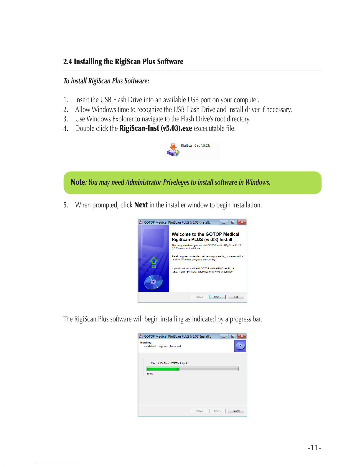
1. Insert the USB Flash Drive into an available USB port on your computer.
2. Allow Windows time to recognize the USB Flash Drive and install driver if necessary.
3. Use Windows Explorer to navigate to the Flash Drive’s root directory.
4. Double click the RigiScan-Inst (v5.03).exe excecutable le.
5. When prompted, click Next in the installer window to begin installation.
The RigiScan Plus software will begin installing as indicated by a progress bar.
Note: You may need Administrator Priveleges to install software in Windows.
Page 12
-12-
RIGISCAN
®
(User Guide)
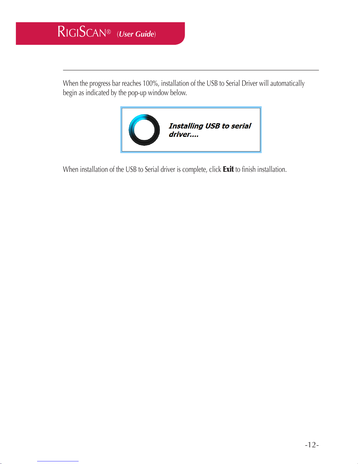
When the progress bar reaches 100%, installation of the USB to Serial Driver will automatically
begin as indicated by the pop-up window below.
When installation of the USB to Serial driver is complete, click Exit to nish installation.
Page 13
-13-
Chapter 3: Software Operation
3.1 Starting RigiScan Plus
To start the RigiScan Plus application:
1. Double-click the RigiScan icon on the desktop
or
1. Click the Start button on the task bar
2. Navigate to All Programs -> GOTOP Medical RigiScan PLUS
3. Click RigiScan
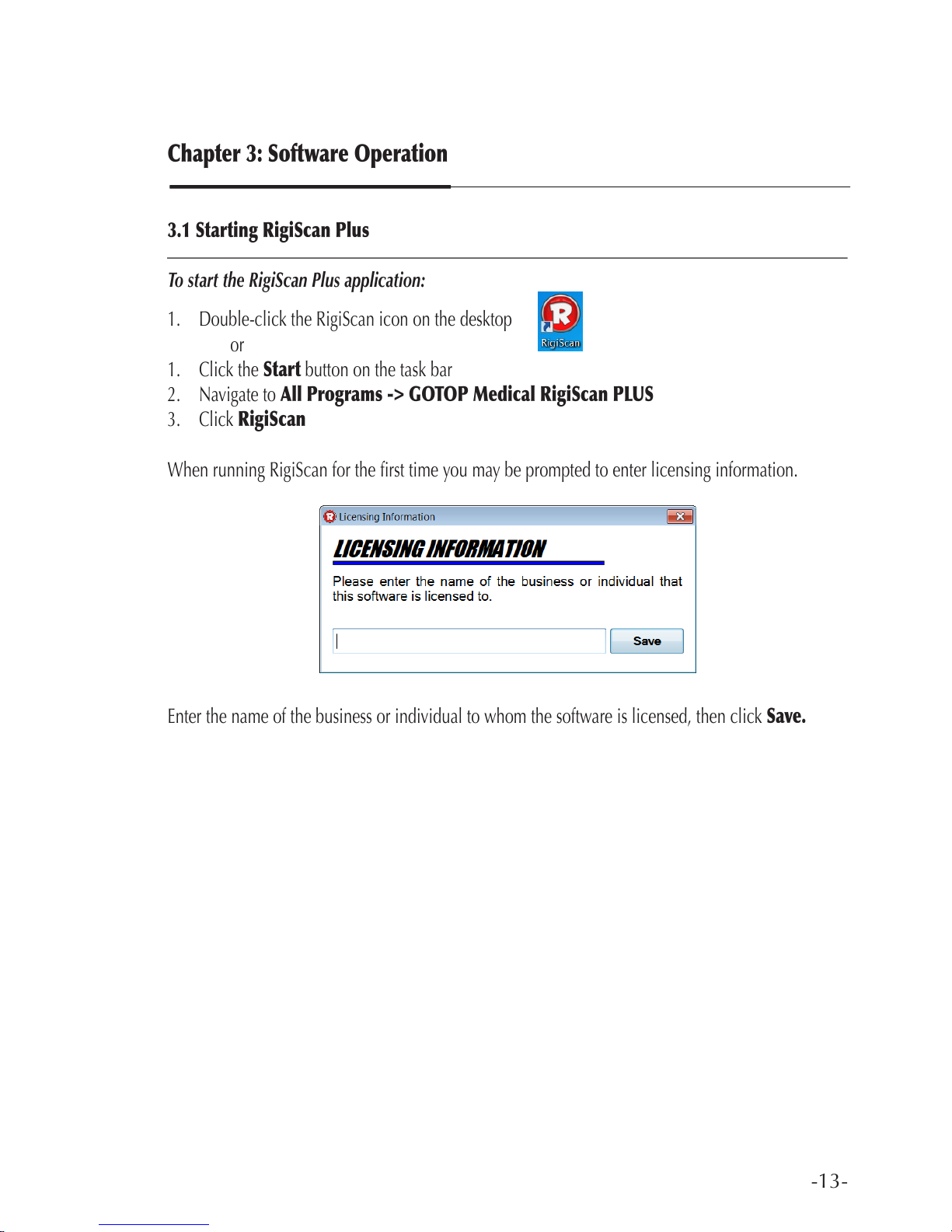
When running RigiScan for the rst time you may be prompted to enter licensing information.
Enter the name of the business or individual to whom the software is licensed, then click Save.
Page 14

-14-
RIGISCAN
®
(User Guide)
3.2 The RigiScan Plus Home Screen
When you start the RigiScan Plus software, the RigiScan Plus Home Screen will appear in a new
window.
A column of buttons, along with functional descriptions of each are provided.
• RigiScan - opens the RigiScan Control window (see Section 3.3)
• Patient Mgmt - opens the Patient Management window (see Section 3.4)
• Reports - opens the Report Manager window (see Section 3.5)
• Data Mgmt - opens the Data Management window (see Section 3.6)
• Settings - opens the RigiScan Settings window (see Section 3.7)
Page 15

-15-
3.3 RigiScan Control Window
Clicking the RigiScan button on the RigiScan Plus Home Screen opens the RigiScan Control window.
Here the user may download session data from a previous ambulatory or real-time monitoring session,
initialize the device for a new patient, or start a Real-Time Monitoring session.
If clicking the RigiScan button on the RigiScan Plus Home screen opens the Error Communicating
pop-up window, click OK, verify that the monitor is turned on and properly connected to the PC, and
check that the correct communication port is selected in the Setting window (see Section 3.7). It may
be necessary to power cycle the device.
Page 16

-16-
Initializing the Monitor
To Initialize the Device (New Patient):
1. Click the Initialize Device button in the RigiScan Control window. This opens the Device Ini-
tialization window.
2. Click the Add New button to add a new patient. This opens the Patient Information window.
3. Enter pertinent information into the Patient Information window (see Section 3.4 for details).
4. Click the button.
5. Click the button in the Patient Information window to return to the Device Initialization
window.
6. When prompted with the Conrm Close pop-up window, click OK.
7. The Patient ID you just entered should now be displayed in the Device Initialization window.
8. Select either Nocturnal or Provocative from the Test Method drop-down menu.
9. Click OK to complete initialization and return to the RigiScan Control window.
To Initialize the Device (Existing Patient):
1. Click the Initialize Device button in the RigiScan Control window. This opens the Device Ini-
tialization window.
2. Click the Select Existing button. This opens the Patient Management window.
3. Use the Search and Quick Search features as necessary to locate the desired patient record (see
Section 3.4 for Search and Quick Search details).
4. Double-click the desired patient record to close the Patient Management window and return to
the Device Initialization window. The Patient ID you selected should now be displayed in the
Device Initialization window.
5. Select either Nocturnal or Provocative from the Test Method drop-down menu.
6. Click OK to complete initialization and return to the RigiScan Control window.
RIGISCAN
®
(User Guide)
Page 17
-17-
To Start Monitoring Session:
See Chapter 5: Patient Testing for details on starting Real-Time and Ambulatory Monitoring Sessions.
To Download Patient Data (following a monitoring session):
1. Following an ambulatory or real-time monitoring session, connect the device to the PC via the
supplied communication cable.
2. Turn the device on, if it isn’t already. It may be necessary to power cycle the device to re-establish
communications.
3. Navigate to the RigiScan Control window.
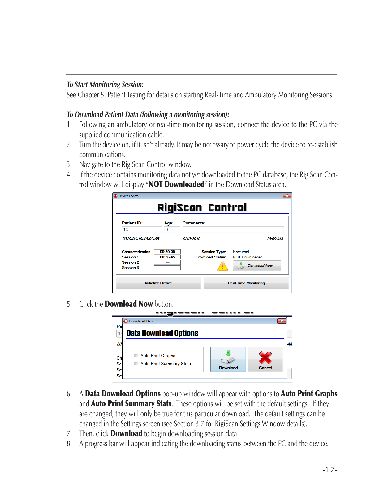
4. If the device contains monitoring data not yet downloaded to the PC database, the RigiScan Con-
trol window will display “NOT Downloaded” in the Download Status area.
5. Click the Download Now button.
6. A Data Download Options pop-up window will appear with options to Auto Print Graphs
and Auto Print Summary Stats. These options will be set with the default settings. If they
are changed, they will only be true for this particular download. The default settings can be
changed in the Settings screen (see Section 3.7 for RigiScan Settings Window details).
7. Then, click Download to begin downloading session data.
8. A progress bar will appear indicating the downloading status between the PC and the device.
Page 18
-18-
RIGISCAN
®
(User Guide)
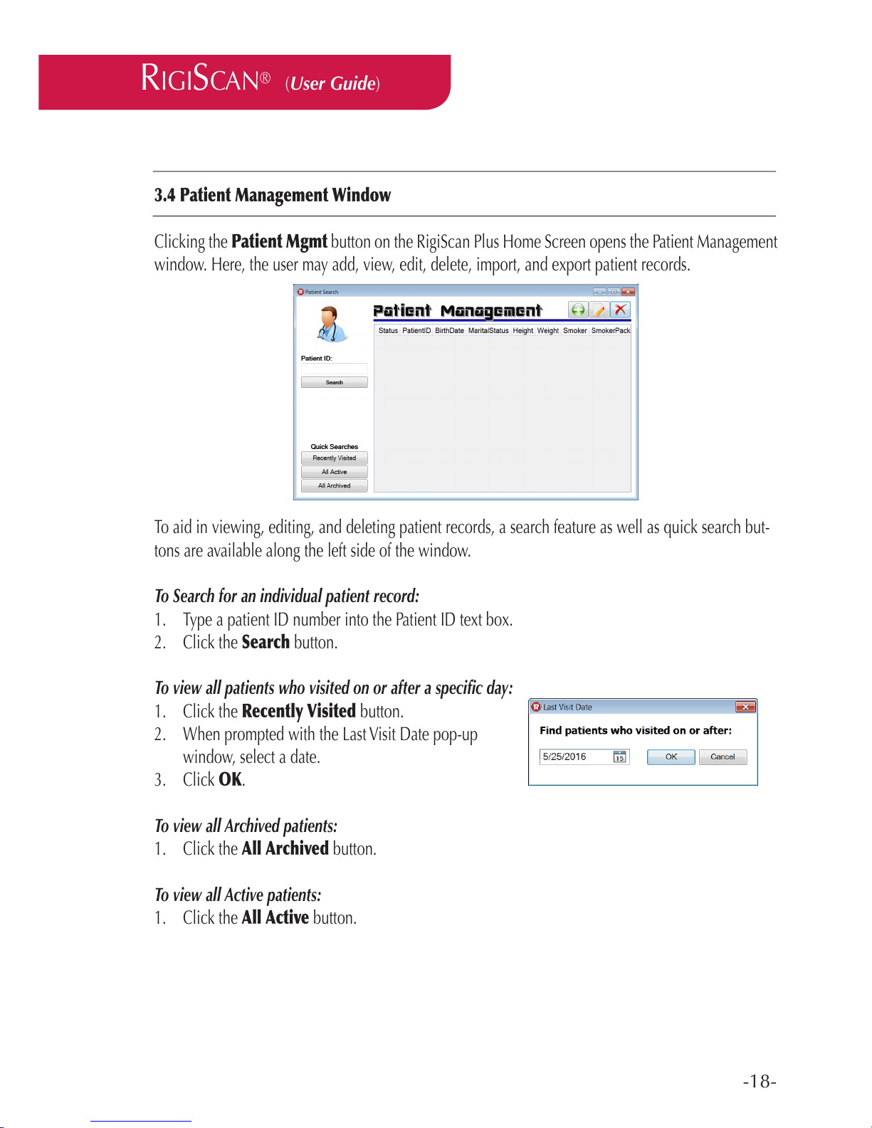
3.4 Patient Management Window
Clicking the Patient Mgmt button on the RigiScan Plus Home Screen opens the Patient Management
window. Here, the user may add, view, edit, delete, import, and export patient records.
To aid in viewing, editing, and deleting patient records, a search feature as well as quick search but-
tons are available along the left side of the window.
To Search for an individual patient record:
1. Type a patient ID number into the Patient ID text box.
2. Click the Search button.
To view all patients who visited on or after a specic day:
1. Click the Recently Visited button.
2. When prompted with the Last Visit Date pop-up
window, select a date.
3. Click OK.
To view all Archived patients:
1. Click the All Archived button.
To view all Active patients:
1. Click the All Active button.
Page 19
-19-
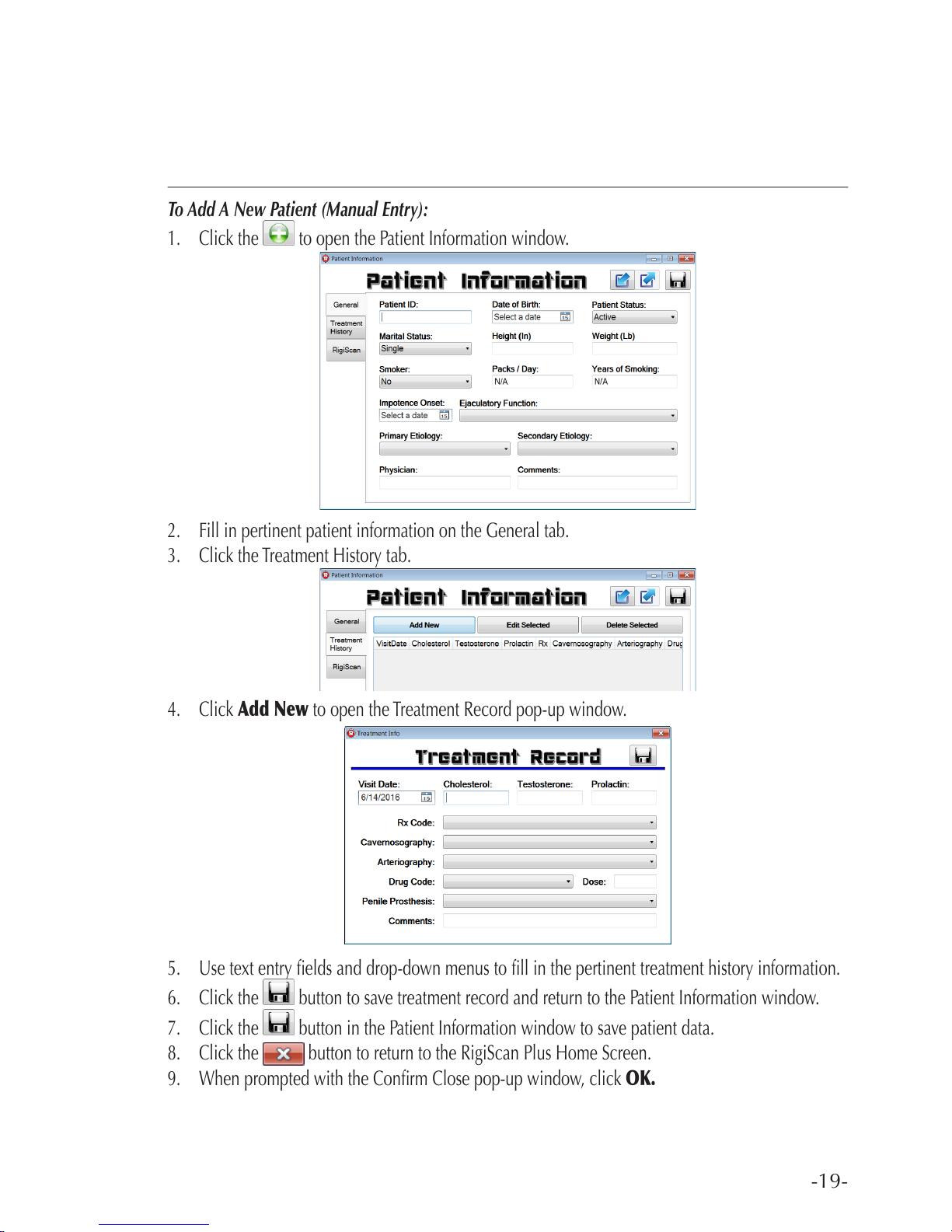
To Add A New Patient (Manual Entry):
1. Click the to open the Patient Information window.
2. Fill in pertinent patient information on the General tab.
3. Click the Treatment History tab.
4. Click Add New to open the Treatment Record pop-up window.
5. Use text entry elds and drop-down menus to ll in the pertinent treatment history information.
6. Click the button to save treatment record and return to the Patient Information window.
7. Click the button in the Patient Information window to save patient data.
8. Click the button to return to the RigiScan Plus Home Screen.
9. When prompted with the Conrm Close pop-up window, click OK.
Page 20

-20-
RIGISCAN
®
(User Guide)
To Import a New Patient From File:
1. Click the button to open the Patient Information window.
2. Click the button.
3. Use the dialog box to navigate to and select the le to import data from (usually a le with
extension “.dat”).
4. Click Open in the dialog box.
5. Click the button to save patient record.
6. Click the button to return to the RigiScan Plus Home Screen.
7. When prompted with the Conrm Close pop-up window, click OK.
To Edit an Existing Patient Record:
1. Click the Patient ID of the record you wish to edit, then click the button to open the Pa-
tient Information window.
or
Double-click the Patient ID of the record you wish to edit to open the Patient Information
window.
2. Modify elds in the General tab as necessary.
3. Click the button to save patient record.
4. In the Treatment History tab, use the Add New and Edit Selected buttons to create or modify
treatment records as done in To Add A New Patient (Manual Entry).
5. Use the Delete Selected button to delete existing treatment records.
6. Click the button to save changes made to treatment records.
7. In the RigiScan tab, use the Delete Selected Group button if you wish to remove any RigiScan
data from the patient record.
8. Click the button to save changes made to session records.
9. Click the button to return to the RigiScan Plus Home Screen.
10. When prompted with the Conrm Close pop-up window, click OK.
Page 21
-21-
To View Existing Patient Data:
1. Double-click the Patient ID of the record you wish to view.
2. Use the tabs along the left side of the Patient Information window to view General, Treatment
History, and RigiScan tabs.
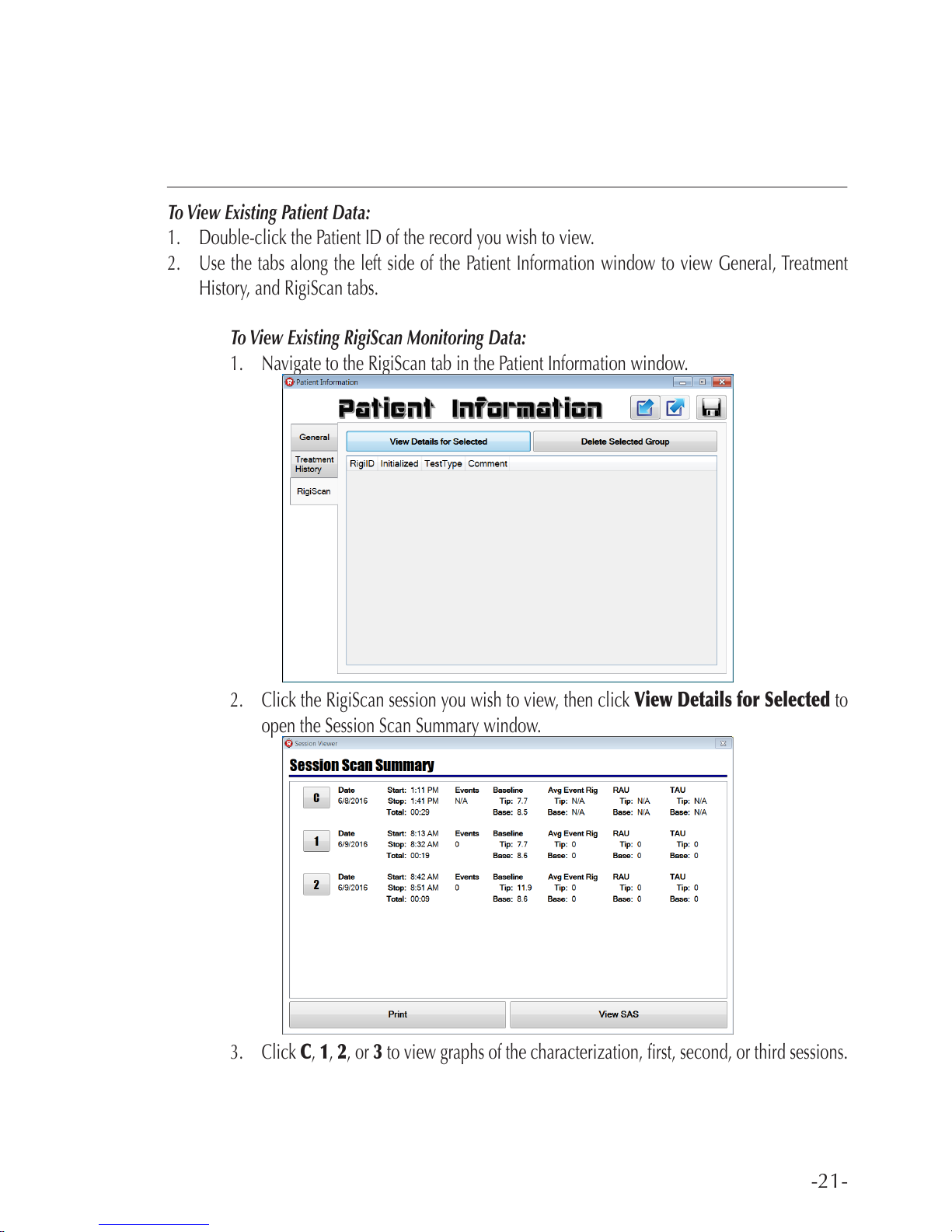
To View Existing RigiScan Monitoring Data:
1. Navigate to the RigiScan tab in the Patient Information window.
2. Click the RigiScan session you wish to view, then click View Details for Selected to
open the Session Scan Summary window.
3. Click C, 1, 2, or 3 to view graphs of the characterization, rst, second, or third sessions.
Page 22

-22-
RIGISCAN
®
(User Guide)
4. From the graph screen, you can set the horizontal scale with the Scale drop down
menu; set a threshold to be displayed on any of the graphs using the Thresh. button;
print the graphs using the Print button; or return to the Session Scan Summary window
using the button.
5. From the Session Scan Summary window, you can click the View SAS button to open
the Session SAS Viewer window.
6. From the Session SAS Viewer window you can view reports for each session individually
or a summary report of all session using the tabs on the left.
7. To print an SAS report, click the button, then follow the on-screen instructions to
select a printer.
Page 23
-23-
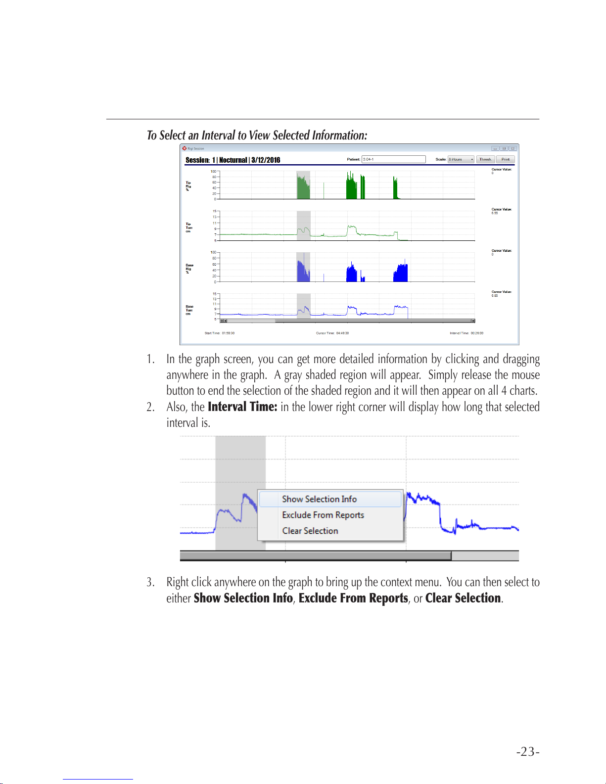
To Select an Interval to View Selected Information:
1. In the graph screen, you can get more detailed information by clicking and dragging
anywhere in the graph. A gray shaded region will appear. Simply release the mouse
button to end the selection of the shaded region and it will then appear on all 4 charts.
2. Also, the Interval Time: in the lower right corner will display how long that selected
interval is.
3. Right click anywhere on the graph to bring up the context menu. You can then select to
either Show Selection Info, Exclude From Reports, or Clear Selection.
Page 24
-24-
RIGISCAN
®
(User Guide)
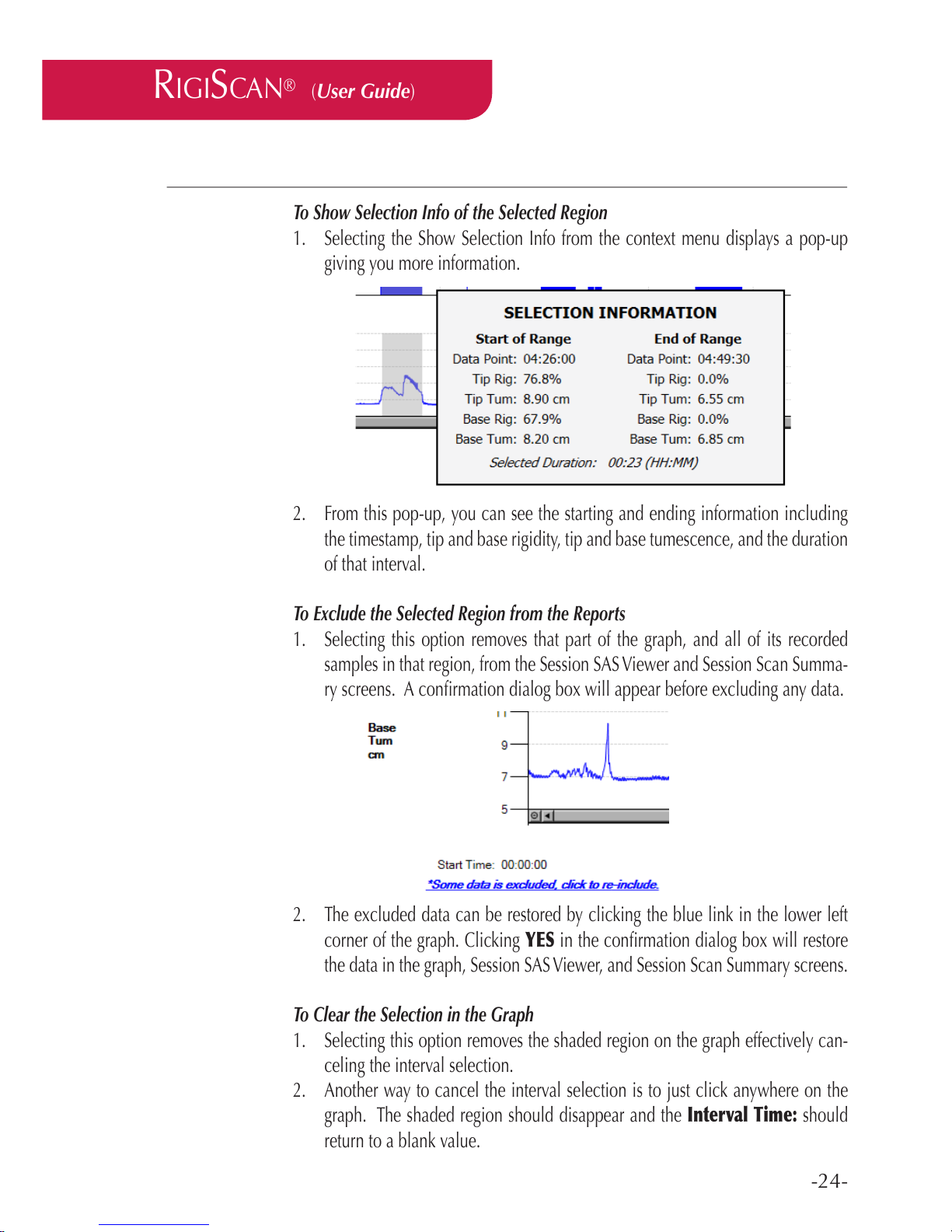
To Show Selection Info of the Selected Region
1. Selecting the Show Selection Info from the context menu displays a pop-up
giving you more information.
2. From this pop-up, you can see the starting and ending information including
the timestamp, tip and base rigidity, tip and base tumescence, and the duration
of that interval.
To Exclude the Selected Region from the Reports
1. Selecting this option removes that part of the graph, and all of its recorded
samples in that region, from the Session SAS Viewer and Session Scan Summa-
ry screens. A conrmation dialog box will appear before excluding any data.
2. The excluded data can be restored by clicking the blue link in the lower left
corner of the graph. Clicking YES in the conrmation dialog box will restore
the data in the graph, Session SAS Viewer, and Session Scan Summary screens.
To Clear the Selection in the Graph
1. Selecting this option removes the shaded region on the graph effectively can-
celing the interval selection.
2. Another way to cancel the interval selection is to just click anywhere on the
graph. The shaded region should disappear and the Interval Time: should
return to a blank value.
Page 25
-25-
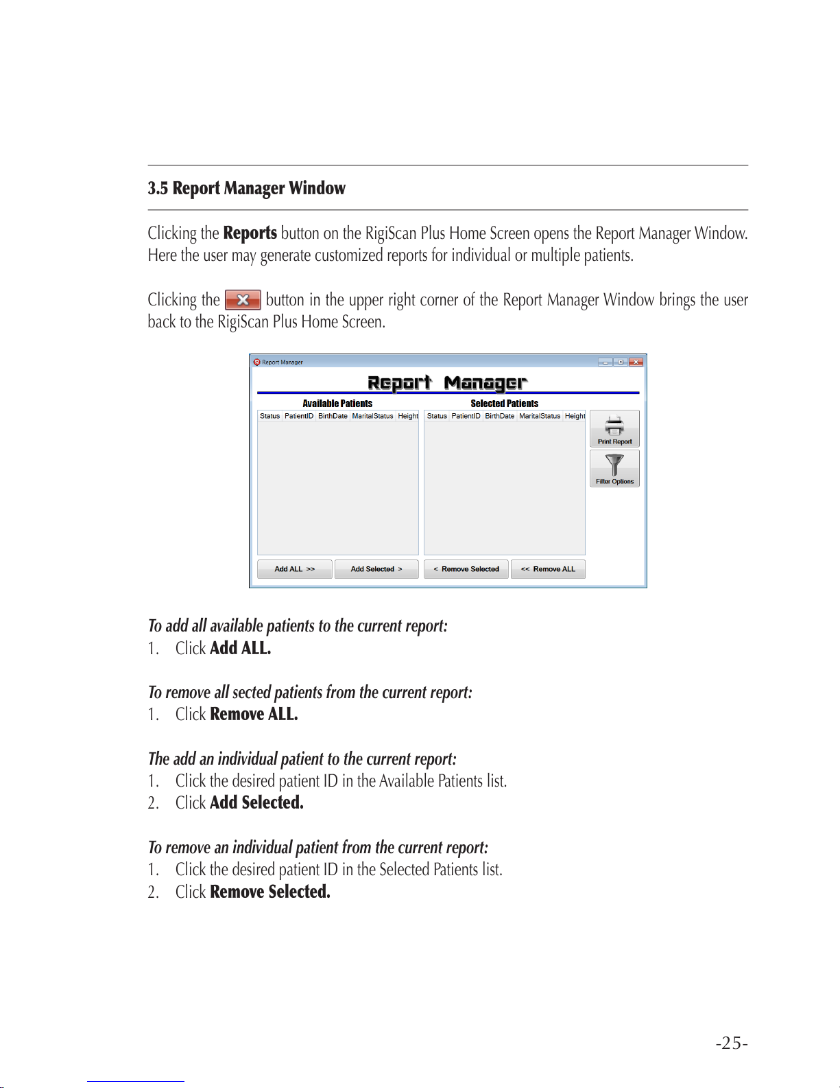
3.5 Report Manager Window
Clicking the Reports button on the RigiScan Plus Home Screen opens the Report Manager Window.
Here the user may generate customized reports for individual or multiple patients.
Clicking the button in the upper right corner of the Report Manager Window brings the user
back to the RigiScan Plus Home Screen.
To add all available patients to the current report:
1. Click Add ALL.
To remove all sected patients from the current report:
1. Click Remove ALL.
The add an individual patient to the current report:
1. Click the desired patient ID in the Available Patients list.
2. Click Add Selected.
To remove an individual patient from the current report:
1. Click the desired patient ID in the Selected Patients list.
2. Click Remove Selected.
Page 26
-26-
RIGISCAN
®
(User Guide)
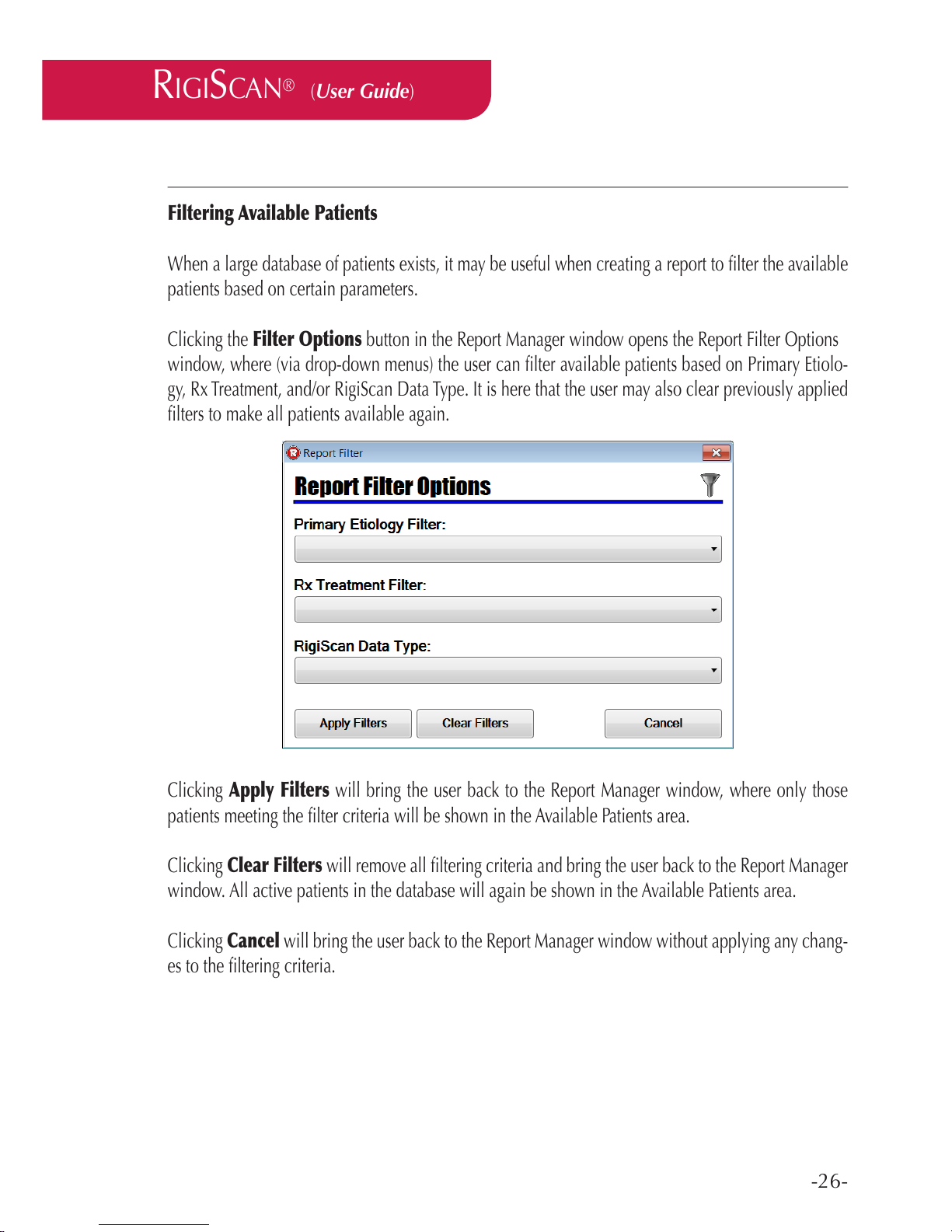
Filtering Available Patients
When a large database of patients exists, it may be useful when creating a report to lter the available
patients based on certain parameters.
Clicking the Filter Options button in the Report Manager window opens the Report Filter Options
window, where (via drop-down menus) the user can lter available patients based on Primary Etiolo-
gy, Rx Treatment, and/or RigiScan Data Type. It is here that the user may also clear previously applied
lters to make all patients available again.
Clicking Apply Filters will bring the user back to the Report Manager window, where only those
patients meeting the lter criteria will be shown in the Available Patients area.
Clicking Clear Filters will remove all ltering criteria and bring the user back to the Report Manager
window. All active patients in the database will again be shown in the Available Patients area.
Clicking Cancel will bring the user back to the Report Manager window without applying any chang-
es to the ltering criteria.
Page 27
-27-
Report Selector
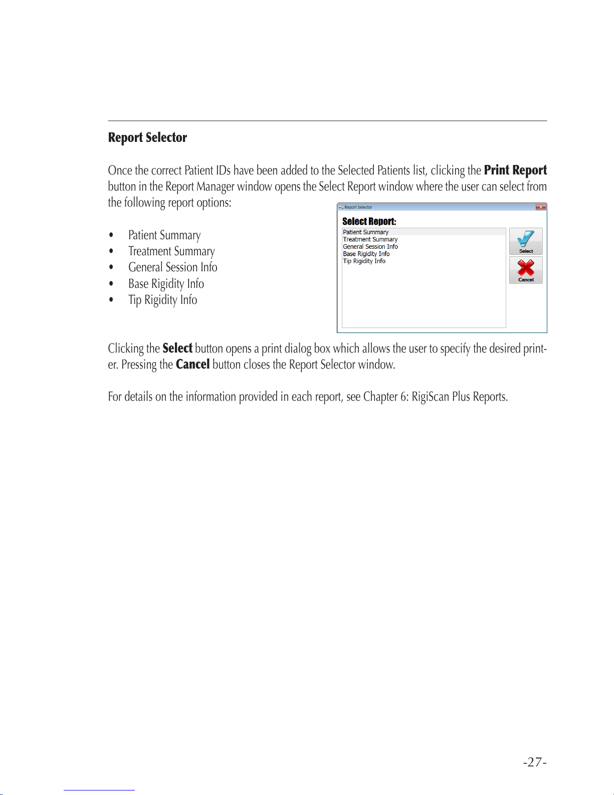
Once the correct Patient IDs have been added to the Selected Patients list, clicking the Print Report
button in the Report Manager window opens the Select Report window where the user can select from
the following report options:
• Patient Summary
• Treatment Summary
• General Session Info
• Base Rigidity Info
• Tip Rigidity Info
Clicking the Select button opens a print dialog box which allows the user to specify the desired print-
er. Pressing the Cancel button closes the Report Selector window.
For details on the information provided in each report, see Chapter 6: RigiScan Plus Reports.
Page 28
-28-
RIGISCAN
®
(User Guide)
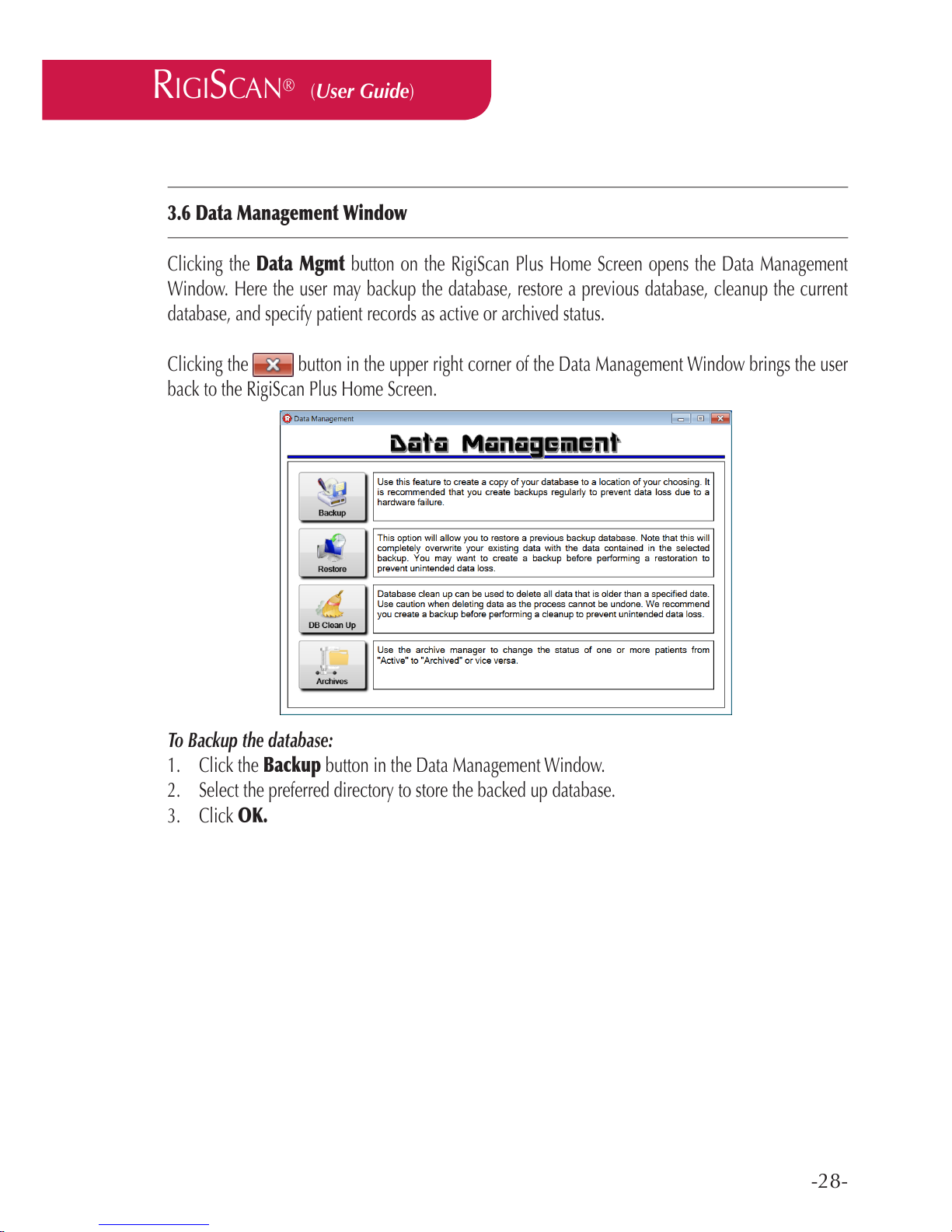
3.6 Data Management Window
Clicking the Data Mgmt button on the RigiScan Plus Home Screen opens the Data Management
Window. Here the user may backup the database, restore a previous database, cleanup the current
database, and specify patient records as active or archived status.
Clicking the button in the upper right corner of the Data Management Window brings the user
back to the RigiScan Plus Home Screen.
To Backup the database:
1. Click the Backup button in the Data Management Window.
2. Select the preferred directory to store the backed up database.
3. Click OK.
Page 29
-29-
To Restore a previously backed up database:
1. To avoid inadvertant loss of data, it is recommeded to always backup the current database prior to
using the Restore feature. The Restore feature completely overwrites the current database.
2. Click the Restore button in the Data Management window.
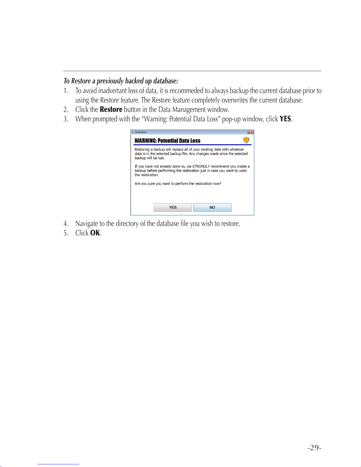
3. When prompted with the “Warning: Potential Data Loss” pop-up window, click YES.
4. Navigate to the directory of the database le you wish to restore.
5. Click OK.
Page 30
-30-
RIGISCAN
®
(User Guide)
To Clean Up database:
1. To avoid the inadvertant deletion of important data, it is strongly recommended to backup the
database prior to using the DB Clean Up feature.
2. Click the DB Clean Up button.
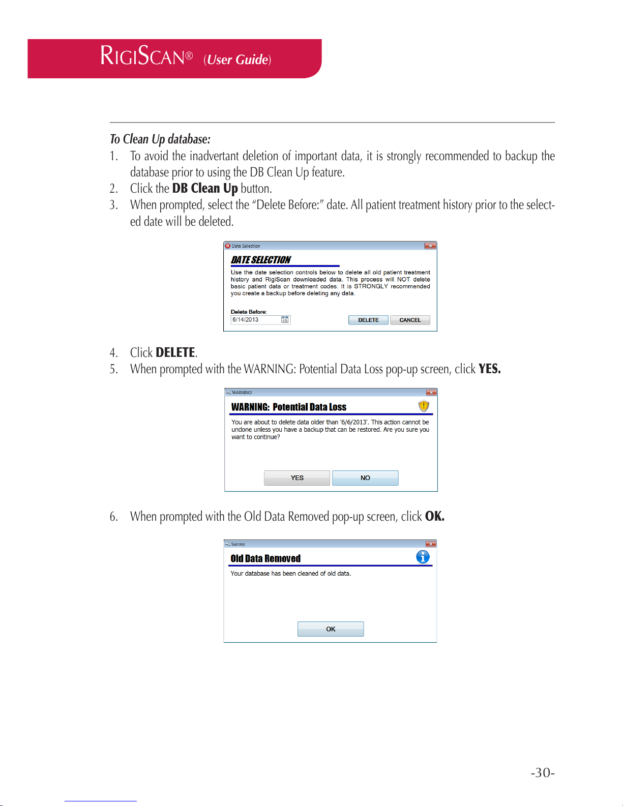
3. When prompted, select the “Delete Before:” date. All patient treatment history prior to the select-
ed date will be deleted.
4. Click DELETE.
5. When prompted with the WARNING: Potential Data Loss pop-up screen, click YES.
6. When prompted with the Old Data Removed pop-up screen, click OK.
Page 31
-31-
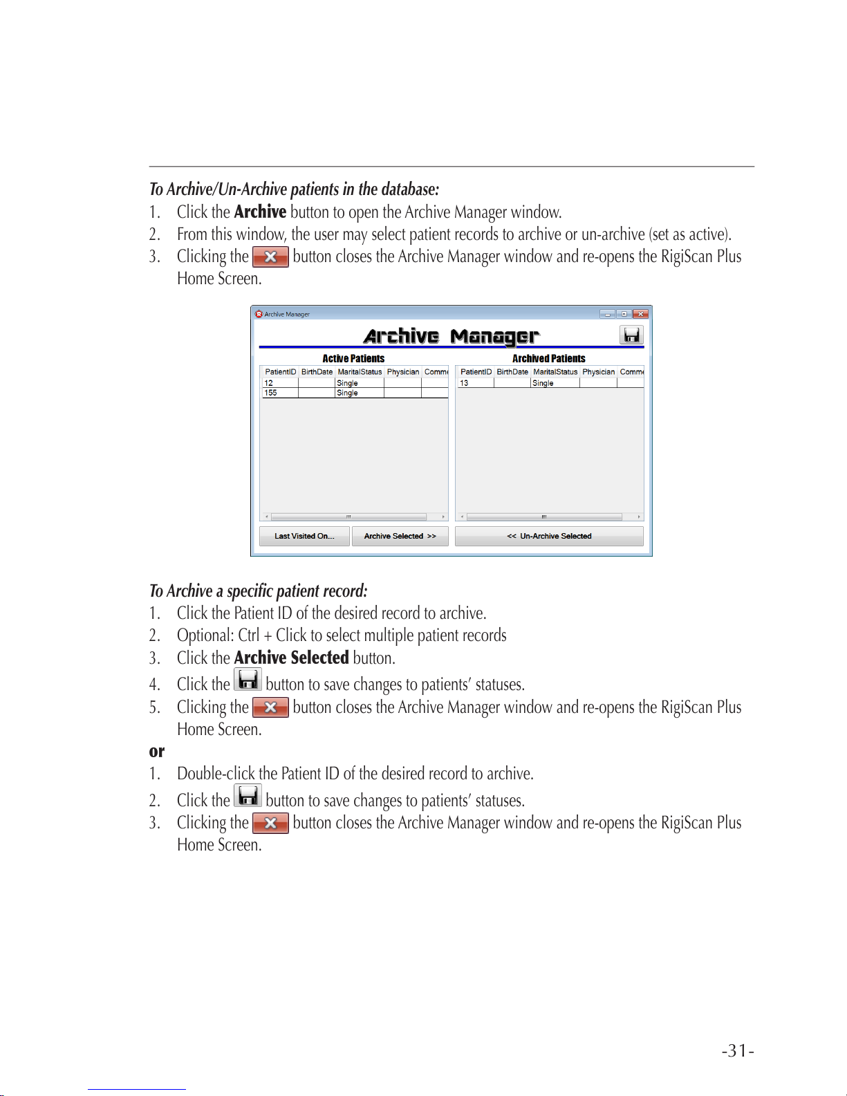
To Archive/Un-Archive patients in the database:
1. Click the Archive button to open the Archive Manager window.
2. From this window, the user may select patient records to archive or un-archive (set as active).
3. Clicking the button closes the Archive Manager window and re-opens the RigiScan Plus
Home Screen.
To Archive a specic patient record:
1. Click the Patient ID of the desired record to archive.
2. Optional: Ctrl + Click to select multiple patient records
3. Click the Archive Selected button.
4. Click the button to save changes to patients’ statuses.
5. Clicking the button closes the Archive Manager window and re-opens the RigiScan Plus
Home Screen.
or
1. Double-click the Patient ID of the desired record to archive.
2. Click the button to save changes to patients’ statuses.
3. Clicking the button closes the Archive Manager window and re-opens the RigiScan Plus
Home Screen.
Page 32
-32-
RIGISCAN
®
(User Guide)
To Archive all patients whose last visit occured before a certain date:
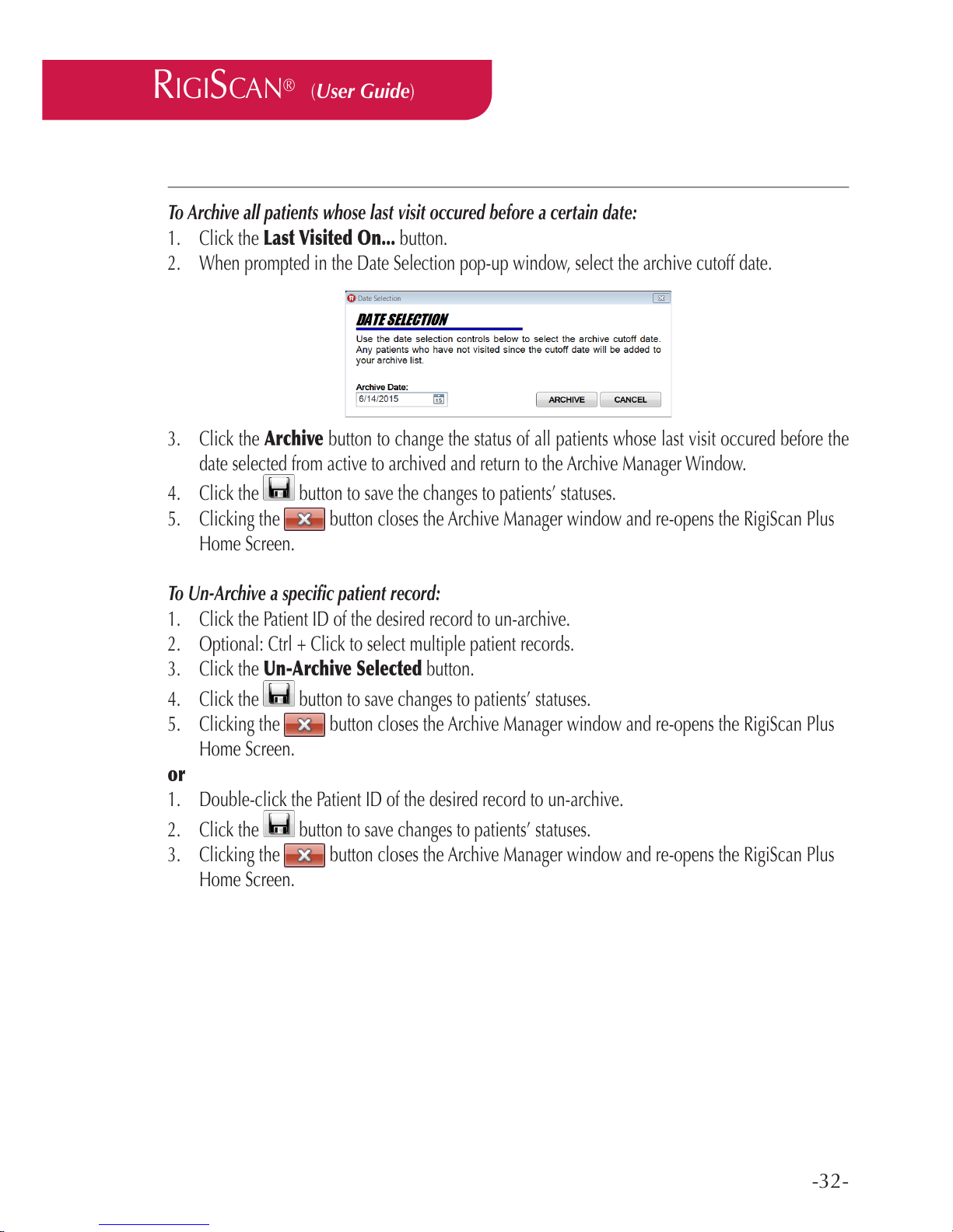
1. Click the Last Visited On... button.
2. When prompted in the Date Selection pop-up window, select the archive cutoff date.
3. Click the Archive button to change the status of all patients whose last visit occured before the
date selected from active to archived and return to the Archive Manager Window.
4. Click the button to save the changes to patients’ statuses.
5. Clicking the button closes the Archive Manager window and re-opens the RigiScan Plus
Home Screen.
To Un-Archive a specic patient record:
1. Click the Patient ID of the desired record to un-archive.
2. Optional: Ctrl + Click to select multiple patient records.
3. Click the Un-Archive Selected button.
4. Click the button to save changes to patients’ statuses.
5. Clicking the button closes the Archive Manager window and re-opens the RigiScan Plus
Home Screen.
or
1. Double-click the Patient ID of the desired record to un-archive.
2. Click the button to save changes to patients’ statuses.
3. Clicking the button closes the Archive Manager window and re-opens the RigiScan Plus
Home Screen.
Page 33
-33-
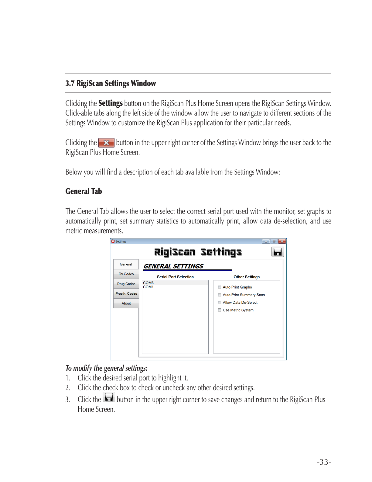
3.7 RigiScan Settings Window
Clicking the Settings button on the RigiScan Plus Home Screen opens the RigiScan Settings Window.
Click-able tabs along the left side of the window allow the user to navigate to different sections of the
Settings Window to customize the RigiScan Plus application for their particular needs.
Clicking the button in the upper right corner of the Settings Window brings the user back to the
RigiScan Plus Home Screen.
Below you will nd a description of each tab available from the Settings Window:
General Tab
The General Tab allows the user to select the correct serial port used with the monitor, set graphs to
automatically print, set summary statistics to automatically print, allow data de-selection, and use
metric measurements.
To modify the general settings:
1. Click the desired serial port to highlight it.
2. Click the check box to check or uncheck any other desired settings.
3. Click the button in the upper right corner to save changes and return to the RigiScan Plus
Home Screen.
Page 34
-34-
RIGISCAN
®
(User Guide)
Serial Port Selection:
1. Select the COM port that corresponds with the desired RigiScan. They are identied as “COM#”
where the # is a number assigned by the Windows operating system.
2. A COM / Serial port may need to be deliberately selected since the application may not automat-
ically select it when it is connected to the PC.
Serial Port Identication:
1. If there are multiple devices or even other COM ports that are being used on your PC, you can
nd out more about them by going into Device Manager on your PC.
2. To open the Device Manager, open the “Run” dialog box by pressing and holding the Windows
key, then press the R key (“Run”). In the Open textbox, type “devmgmt.msc”. Then click OK or
press the Enter key.
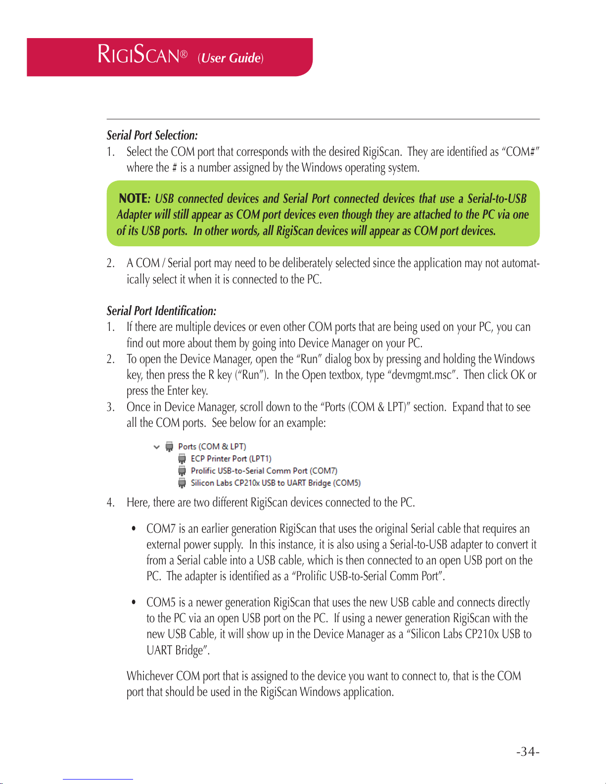
3. Once in Device Manager, scroll down to the “Ports (COM & LPT)” section. Expand that to see
all the COM ports. See below for an example:
4. Here, there are two different RigiScan devices connected to the PC.
• COM7 is an earlier generation RigiScan that uses the original Serial cable that requires an
external power supply. In this instance, it is also using a Serial-to-USB adapter to convert it
from a Serial cable into a USB cable, which is then connected to an open USB port on the
PC. The adapter is identied as a “Prolic USB-to-Serial Comm Port”.
• COM5 is a newer generation RigiScan that uses the new USB cable and connects directly
to the PC via an open USB port on the PC. If using a newer generation RigiScan with the
new USB Cable, it will show up in the Device Manager as a “Silicon Labs CP210x USB to
UART Bridge”.
Whichever COM port that is assigned to the device you want to connect to, that is the COM
port that should be used in the RigiScan Windows application.
NOTE: USB connected devices and Serial Port connected devices that use a Serial-to-USB
Adapter will still appear as COM port devices even though they are attached to the PC via one
of its USB ports. In other words, all RigiScan devices will appear as COM port devices.
Page 35

-35-
Other Settings:
Auto Print Graphs:
This option allows the automatic printing of the Rigi Session Graphs once the downloading
of session data is complete. This is where the default setting of this option is set. This setting can be temporarily overridden from the Data Download Options pop-up window (see
Section 3.3 for RigiScan Control Window), but the default setting will be used upon the next
Data Download.
Auto Print Summary Stats:
This option allows the automatic printing of the Summary Analysis Statistics once the downloading of session data is complete. This is where the default setting of this option is set. This
setting can be temporarily overridden from the Data Download Options pop-up window (see
Section 3.3 for RigiScan Control Window), but the default setting will be used upon the next
Data Download.
Allow Data De-Select:
This option allows the removal of data in the graphs. By clicking and dragging anywhere
in the graph, a gray shaded region will appear. Simply release the mouse button to end the
selection of the shaded region and it will then appear on all 4 charts. Then right clicking
anywhere on the graph brings up the context menu. By selecting Exclude From Reports,
that data will be removed from the graph and those data samples will be removed from the
statistics and reports. Multiple regions can be removed, if desired. To restore all of the ex-
cluded data, simple click on the blue link in the lower left corner of the graph. Clicking YES
in the conrmation dialog box will restore the data in the graph and the reports.
Allow Metric System:
This option allows the Height and Weight measurements to switch between the Imperial and
Metric systems. Patient’s Height and Weight will either be in inches and pounds or they will
be in centimeters and kilograms. Checking this box will set the Height to use cm and the
Weight to use kg. Unchecking this box will set the Height to use inches and the Weight to
use pounds.
Page 36
-36-
RIGISCAN
®
(User Guide)
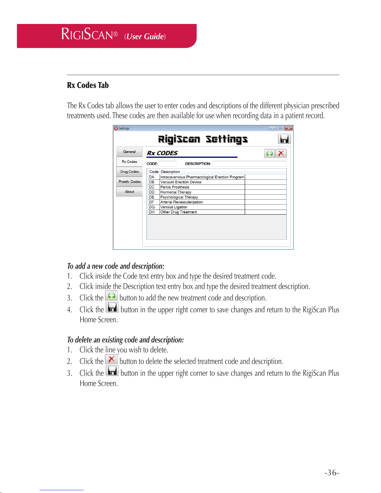
Rx Codes Tab
The Rx Codes tab allows the user to enter codes and descriptions of the different physician prescribed
treatments used. These codes are then available for use when recording data in a patient record.
To add a new code and description:
1. Click inside the Code text entry box and type the desired treatment code.
2. Click inside the Description text entry box and type the desired treatment description.
3. Click the button to add the new treatment code and description.
4. Click the button in the upper right corner to save changes and return to the RigiScan Plus
Home Screen.
To delete an existing code and description:
1. Click the line you wish to delete.
2. Click the button to delete the selected treatment code and description.
3. Click the button in the upper right corner to save changes and return to the RigiScan Plus
Home Screen.
Page 37
-37-
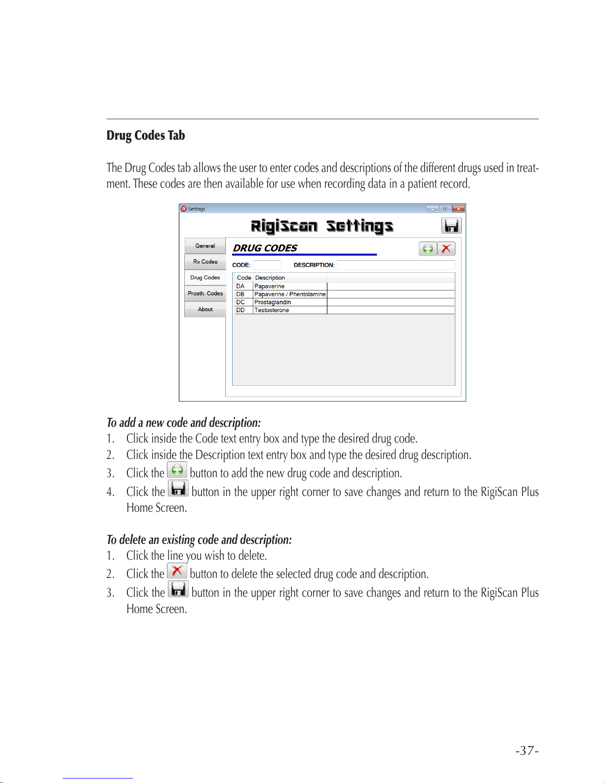
Drug Codes Tab
The Drug Codes tab allows the user to enter codes and descriptions of the different drugs used in treat-
ment. These codes are then available for use when recording data in a patient record.
To add a new code and description:
1. Click inside the Code text entry box and type the desired drug code.
2. Click inside the Description text entry box and type the desired drug description.
3. Click the button to add the new drug code and description.
4. Click the button in the upper right corner to save changes and return to the RigiScan Plus
Home Screen.
To delete an existing code and description:
1. Click the line you wish to delete.
2. Click the button to delete the selected drug code and description.
3. Click the button in the upper right corner to save changes and return to the RigiScan Plus
Home Screen.
Page 38
-38-
RIGISCAN
®
(User Guide)
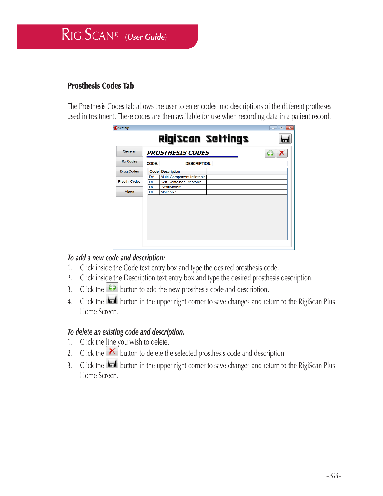
Prosthesis Codes Tab
The Prosthesis Codes tab allows the user to enter codes and descriptions of the different protheses
used in treatment. These codes are then available for use when recording data in a patient record.
To add a new code and description:
1. Click inside the Code text entry box and type the desired prosthesis code.
2. Click inside the Description text entry box and type the desired prosthesis description.
3. Click the button to add the new prosthesis code and description.
4. Click the button in the upper right corner to save changes and return to the RigiScan Plus
Home Screen.
To delete an existing code and description:
1. Click the line you wish to delete.
2. Click the button to delete the selected prosthesis code and description.
3. Click the button in the upper right corner to save changes and return to the RigiScan Plus
Home Screen.
Page 39
-39-
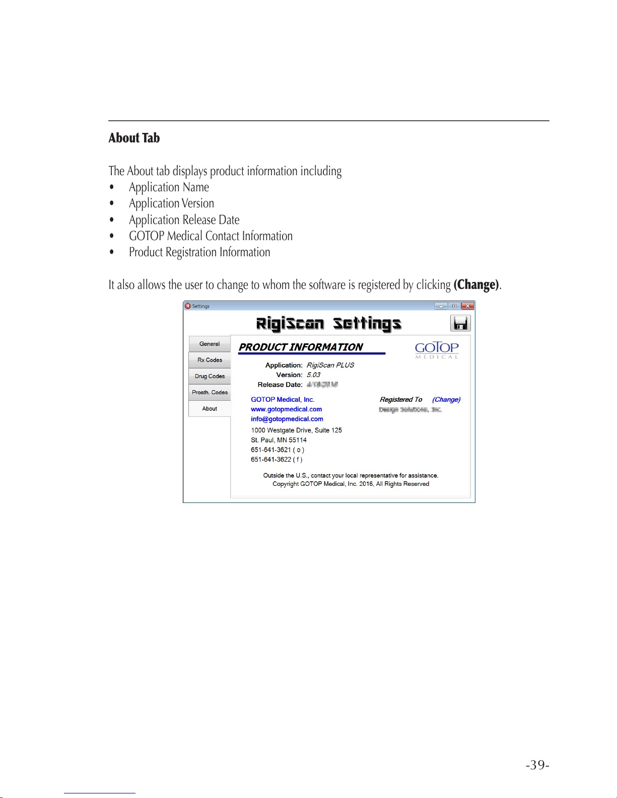
About Tab
The About tab displays product information including
• Application Name
• Application Version
• Application Release Date
• GOTOP Medical Contact Information
• Product Registration Information
It also allows the user to change to whom the software is registered by clicking (Change).
Page 40

-40-
RIGISCAN
®
(User Guide)
Chapter 4: Preparing the RigiScan Plus System for Patient Testing
4.1 Installing the Tension Guides
Prior to each use, inspect the RigiScan Plus Monitor’s Tension Guides, cables and loops to determine
that all parts are in good working order. Replace the Tension Guides if the cables are kinked, frayed or
worn, the boots are loose or otherwise worn or damaged, or the tension guides are crushed or broken.
Because the TIP and BASE Tension Guides are not interchangeable, it is important that you insert
the correct guide into its corresponding guide housing. Notice the two labels on the end of the RigiScan Plus Monitor, marked as TIP and BASE . The BASE tension guide (BLUE boot) must
be installed in the BASE Connector Housing, and the TIP Tension Guide (WHITE boot) must be
installed in the TIP Connector Housing.
To install the tension guides, follow these steps:
1. Verify that the RigiScan Plus Monitor is turned off.
2. Verify that the appropriate Tension Guide (BASE=BLUE, TIP=WHITE) has been selected.
3. Verify that the plastic retention nut on the tension guide has been turned fully towards the boot of
the Tension Guide and the loop fully expanded.
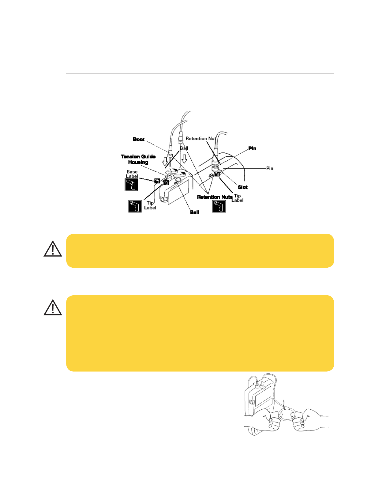
4. Hold the Tension Guide by the boot at the ball-end of the cable and insert it into the corresponding Tension Guide housing on the Monitor.
5. Align the pin on the Tension Guide with the slot in the housing. Push the Tension Guide into the
housing until it is fully inserted and turn approximately 1/4 turn clockwise until the pin is fully
seated in the slot.
WARNING
Replace the Tension Guies if the boots are loose, the cable is kinked or curled, or the Tension
Guide is crushed or broken. Use of damaged or worn Tension Guides may result in patient injury. The Tension Guides must be inserted in the monitor with the tension guide pin fully seated
in the slot at the top of the housing. Use of a RigiScan with improperly inserted tension guides
may result in patient injury. TIP and BASE Tension Guides are not interchangeable! For ease in
identication, the BASE Tension Guide has BLUE boots, the TIP Tension Guide has WHITE boots.
Inserting the Tension Guides in the wrong connector housing may damage the monitor. Turn the
RigiScan Plus Monitor “off” before replacing or removing the Tension Guides/cables. Operating
the monitor without the Tension Guides/cables in place may damage the device or result in inability to insert the Tension Guide.
Page 41
-41-
6. Tighten the plastic retention nut on the tension guide until it contacts the Tension Guide housing.
(see Figure 4-1)
4.2 Removing the Tension Guides
1. Verify that the RigiScan Plus Monitor is turned off.
2. Unscrew the plastic retention nut on the Tension Guide at
the monitor end of the Tension Guide.
3. Expand the loop to its maximum circumference by inserting
your ngers in the loop and slowly applying outward pressure until the loop will no longer expand. (see Figure 4-2)
Fig. 4-1 Installing the Tension Guides
Fig. 4-2 Expanding the Loops
CAUTION: DO NOT over tighten the retention nuts as this will make future removal very
difcult.
CAUTION: Turn the RigiScan Monitor “off” before replacing or removing the Tension Guides/
cables. Operating the Monitor without the Tension Guides/cables in place may damage the device or result in inability to insert the Tension Guides. Care must be taken to remove the tension
guides slowly and gently to avoid damage to the cables or internal mechanisms. Removing the
Tension Guides too quickly may damage the monitor or result in an ‘out-of-phase’ condition and
inability to re-insert the tension guides.
Page 42
-42-
RIGISCAN
®
(User Guide)
4. Push the Tension Guide into the Tension Guide housing on the monitor and turn approximately
1/4 turn counterclockwise until the metal pin moves out of the slot at the far right of the housing.
5. Pull slowly and gently on the Tension Guide boot to remove the Tension Guide and cable from
the monitor.
4.2 Removing the Tension Guides (continued)
4.3 Installing the Loop Covers
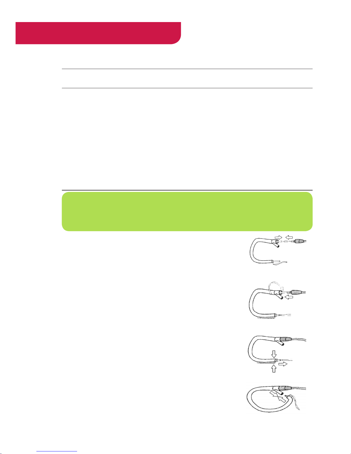
1. Insert the snap end of the Tension Guide cable securely into the feeder tube at the “Y” connect end of the loop cover. (See Figure 4-3A)
2. Hold the loop-cover “Y” connect in one hand and gently pull the
feeder tube and cable through the loop cover until the “Y” connect is
adjacent to the threaded end of the Tension Guide.
3. Hold the Tension Guide boot in one hand, the “Y” connect in the oth-
er and screw the “Y” connect clockwise until it is securely fastened to
the Tension Guide. Do not over tighten. (See Figure 4-3B)
4. Grasp the snap end of the loop cover and remove the feeder tube.
(See Figure 4-3C)
5. Close the loop by holding the fabric directly behind the release tab
and pushing the snap into the receptacle on the “Y” connect. (See
Figure 4-3D)
Fig. 4-3A
Fig. 4-3B
Fig. 4-3C
Fig. 4-3D
NOTE: The loop covers are supplied with a clear plastic feeder tube inside the loop. The feeder
tube is required for installing the loop cover. DO NOT remove the feeder tube until directed
to do so.
Page 43
-43-
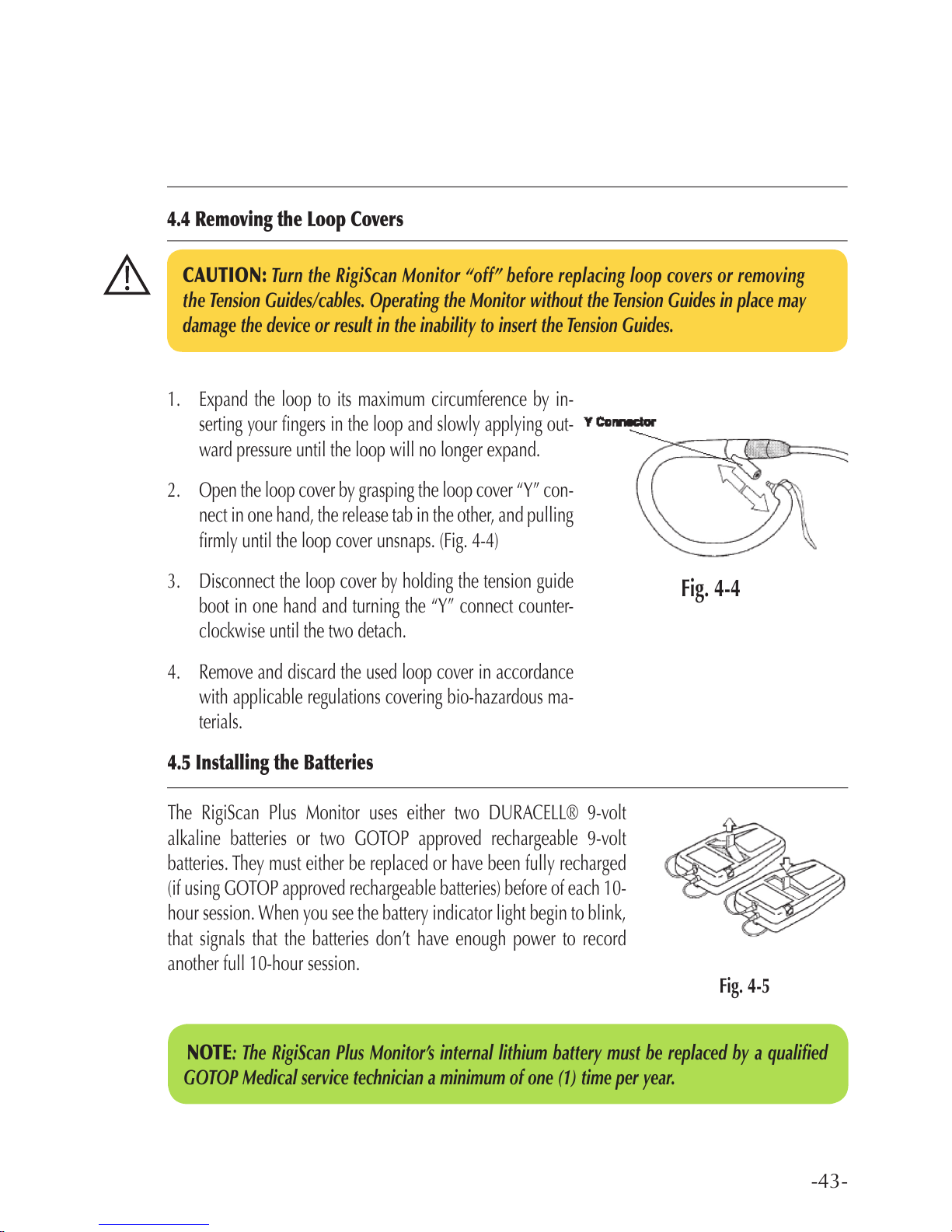
1. Expand the loop to its maximum circumference by in-
serting your ngers in the loop and slowly applying out-
ward pressure until the loop will no longer expand.
2. Open the loop cover by grasping the loop cover “Y” con-
nect in one hand, the release tab in the other, and pulling
rmly until the loop cover unsnaps. (Fig. 4-4)
3. Disconnect the loop cover by holding the tension guide
boot in one hand and turning the “Y” connect counter-
clockwise until the two detach.
4. Remove and discard the used loop cover in accordance
with applicable regulations covering bio-hazardous ma-
terials.
4.5 Installing the Batteries
The RigiScan Plus Monitor uses either two DURACELL® 9-volt
alkaline batteries or two GOTOP approved rechargeable 9-volt
batteries. They must either be replaced or have been fully recharged
(if using GOTOP approved rechargeable batteries) before of each 10-
hour session. When you see the battery indicator light begin to blink,
that signals that the batteries don’t have enough power to record
another full 10-hour session.
CAUTION: Turn the RigiScan Monitor “off” before replacing loop covers or removing
the Tension Guides/cables. Operating the Monitor without the Tension Guides in place may
damage the device or result in the inability to insert the Tension Guides.
4.4 Removing the Loop Covers
Fig. 4-5
Fig. 4-4
NOTE: The RigiScan Plus Monitor’s internal lithium battery must be replaced by a qualied
GOTOP Medical service technician a minimum of one (1) time per year.
Page 44
-44-
4.5 Installing the Batteries (continued)
To replace the 9 V batteries, complete the following steps:
1. Open the battery cover by pulling the black tab in the direction of the arrow.
2. Pull up on the black tab in the battery compartment to release the old batteries. (see Figure 4-5)
3. If using alkaline batteries, discard the old batteries in accordance with applicable regulations. If
using GOTOP approved rechargeable batteries, place them in GOTOP approved battery charger
and allow them to fully charge before re-use.
4. Match the polarity of the new/fully-recharged batteries (+ and –) with those in the battery compartment.
5. Install the new/fully-recharged batteries in the compartment (contact ends rst), pressing them
down into the compartment with your thumbs and replace the compartment cover.
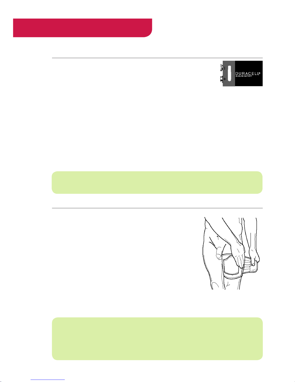
4.6 Attaching the Leg Strap
To attach the leg strap to the patient’s thigh, follow these steps:
1. When possible have the patient complete these steps in a standing position.
2. Wrap the leg strap (supplied in the carrying case) around the
thigh of either leg, with the opening pointing toward the patient’s
penis (see Figure 4-6). If the patient sleeps on his left side, you
should attach the RigiScan Plus Monitor and strap to the left
thigh. If he sleeps on his right side, you should attach the RigiScan Plus Monitor and strap to the right thigh. The strap should be
comfortably snug.
3. After tting the strap securely, slide the RigiScan Plus Monitor
into the holster of the strap.
RIGISCAN
®
(User Guide)
Use Only DURACELL®
9-volt alkaline Batteries
or GOTOP approved
rechargeable 9-volt
batteries
NOTE: If physical disabilities prohibit the patient from attaching the leg strap to his thigh, a
waist strap is supplied to allow the patient to wear the RigiScan Plus Monitor around his abdomen. Connect the two straps together and wrap them around the patient’s waist, with the pocket centered over his penis. Insert the RigiScan Plus Monitor into the pocket with the tensions
guides pointing down toward his penis.
NOTE: Remove the 9-volt batteries from the device if the device will not be used for an extended period.
Fig. 4-6 Attaching
the Leg Strap
Page 45

-45-
Chapter 5: Patient Testing
Patient testing entails recording data with the RigiScan Plus Monitor while it is attached to the patient.
The data that is collected is then downloaded to an IBM compatible computer for evaluation by the clinician. To prepare the RigiScan Plus Monitor for a new study, you must be sure that you have initialized
the RigiScan Plus Monitor with the patient’s proper information. For instructions on how to initialize
the RigiScan Plus Monitor, see Initializing the Monitor in Chapter 3 of this manual.
5.1 Nocturnal and Provocative Collection Modes
Estimating an appropriate baseline for penile circumference is an important parameter in the processing
of rigidity and tumescence data by the RigiScan Plus System Software. There are two different modes
of data collection: Nocturnal and Provocative. Each method processes data differently in order to
establish an accurate estimate of the baseline penile circumference, so it is important to select the
appropriate mode during initialization before you begin testing the patient. For instructions on how to
select the testing mode, see Initializing the Monitor in Chapter 3.
Nocturnal Testing
You should use the Nocturnal Testing mode when you want to monitor nocturnal erections over a period of several hours. This test method can be used while the patient is at home or in a sleep laboratory
setting, and also can be used under Ambulatory or Real-time settings. The Nocturnal Mode is used
when there are multiple erectile events and there is a periodic return to the accid state. This uses the
entire session to calculate the baseline.
Provocative Testing
Provocative Testing is performed when the clinician wants to use an intervention to produce a onetime erectile response. This method of testing is performed over a shorter period of time, usually in
an ofce setting. Intervention might include the injection of a pharmacological agent or visual sexual
stimuli. This test method can also be used under either Ambulatory or Real-time settings. In the Provocative Mode, the RigiScan Plus System records a baseline penile tumescence during the rst fteen
minutes of testing and stores it for later reference. If you are testing in the Real-time mode, the message
CALCULATING BASELINE will ash at the bottom of the screen while the baseline tumescence is
being established. Only when the message BASELINE ESTABLISHED appears on the screen indi-
cating the baseline tumescence is calculated and stored may intervention be given to the patient. If
you are testing in the ambulatory mode, monitoring must be performed for a period of fteen minutes
to establish a baseline value before intervention is given to the patient.
Page 46
-46-
RIGISCAN
®
(User Guide)
5.2 Instructing the Patient
When a patient is being tested in the ambulatory mode at home, you need to explain how to use the
RigiScan Plus Monitor, including giving instructions on how to put it on, start it, and change the batter-
ies. A characterization session is provided for patient education. See section 5.4. Instruct the patient to
wear loose tting clothing when wearing the RigiScan Plus Monitor, such as pajamas or boxer shorts.
See Appendix B: Patient Instructions at the end of this manual to instruct the patient on how to use the
RigiScan Plus Monitor. Provide these instructions to your patients to reference when using the RigiScan
Plus Monitor at home.
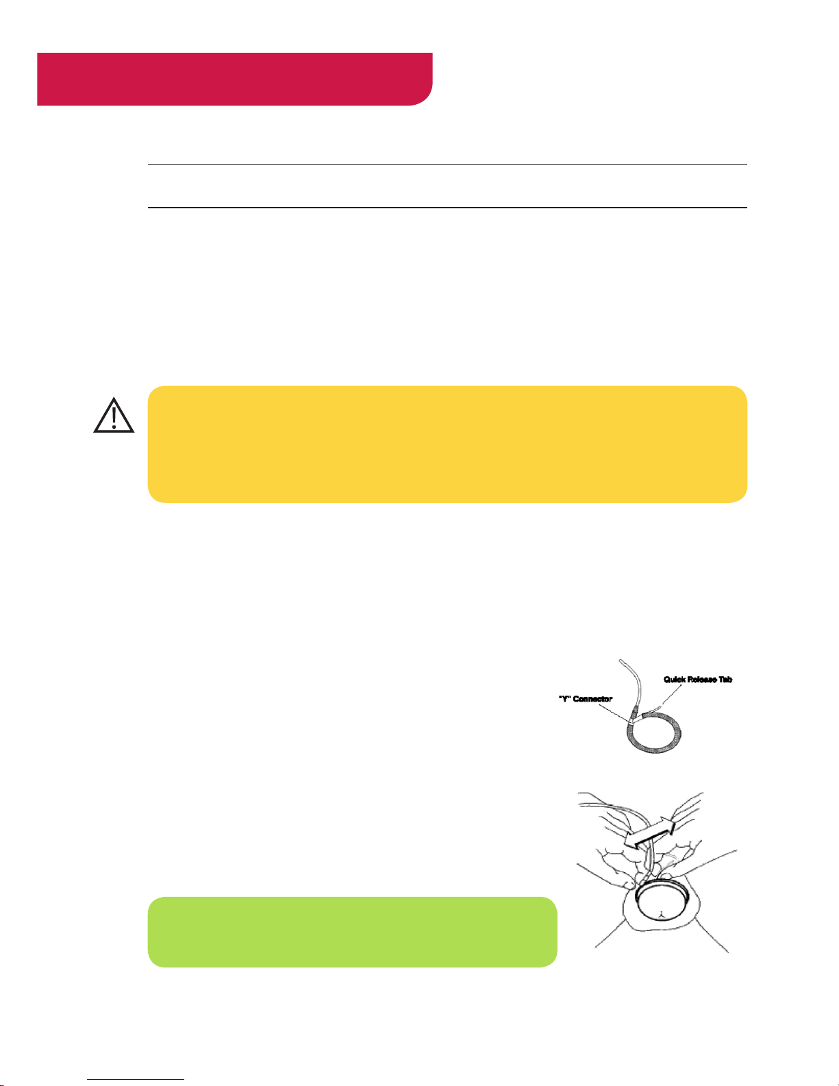
Removing the Loops Quickly
Normally the patient would remove the loops by inserting his ngers
gently into the loops and pulling outward to expand the loops. However, if the patient experiences pain during testing or wants to remove
the loops quickly for any other reason, he can unsnap the loops with
the quick release tab. To do this, instruct the patient to follow these
steps:
1. With one hand, grasp the loop at the “Y”connector. (See Figure
5-1A)
2. With the other hand, grasp the quick release tab and pull it sharp-
ly until the two ends of the loop come apart. (See Figure 5-1B)
It is the responsibility of the physician to assure that adequate instructions and orientation
regarding in-home use of the RigiScan Plus Monitor are given to the patient. These instructions
are provided as a reference only and are not intended to replace the instructions given by the
physician. Inadequate instruction may result in patient injury.
NOTE: For instructions on how to reinstall the loop covers, see
Installing the Loop Covers in Chapter 4.
Fig. 5-1A
Fig. 5-1B
Page 47
-47-
5.3 Testing Patients Using the Real-time and Ambulatory Modes
Real-time Testing
Real-time Monitoring permits the clinician to view data recorded during sessions immediately on
the computer screen. Either Nocturnal or Provocative testing can be performed using the Real-time
Monitoring Option. Battery life during RTM is not an issue since it is being powered by the USB cable.
To collect patient data in the Real-time mode, follow these steps in the exact order given.
1. Connect the RigiScan Plus Monitor to your computer’s communications cable. See Setting Up the
Hardware in Chapter 2.)
2. Initialize the RigiScan Plus Monitor. (See Initialize the Monitor in Chapter 3.)
3. Attach the RigiScan Plus Monitor to the patient’s leg. (See Attaching the Leg Strap in Chapter 4.)
4. Attach the RigiScan Plus Monitor Loops to the patient’s penis: First, t the BASE Loop (blue boot)
over the patient’s penis and position it at the base of the penis. Second, t the TIP Loop (white boot)
over the patient’s penis and position it at the tip of the penis just below the glans.
WARNING: It is IMPORTANT to follow the instructions in the precise order given. Performing
these operations in the wrong sequence may result in improper sampling and cause patient
discomfort.
WARNING: DO NOT turn the RigiScan Monitor on until the loops have been placed on the
patient’s penis. Turning the monitor on before placing the loops will cause continuous rigidity
sampling and may result in patient discomfort, pain, irritation or bruising.
NOTE: The optional Event Marker can be used to mark pertinent points in the data for later
reference, for example when a pharmacological agent is given to the patient. At anytime after
the data stream begins you can press the button on the Event Marker Cable to place vertical
cursor line on the graph. This line becomes a permanent part of the patient’s record, so it will
appear in the session reports. See Connecting the Event Marker in Chapter 2 for instructions on
how to connect the Event Marker.
Page 48
-48-
Real-time Testing (continued)
5. Tu rn t he R igiS can Plus M onit or o n.
6. If it is not already open, open the RigiScan Control window. (See RigiScan Control Window in
Chapter 3.)
7. Click the Real Time Monitoring button. If you initialized the patient data for provocative testing,
the Provocative Real-time Mode Graphs screen will appear. Otherwise, the Nocturnal Real-time
Mode Graphs will appear.
8. Hold the loops in their proper positions until the RigiScan Plus Monitor tightens them. The Base
Loop will tighten rst, followed by the Tip Loop. The loops will not tighten until you have clicked
Real Time Monitoring.
9. To sto p th e Re al-t ime Mo nito ring ses sion , click button to exit the Real-Time Mode screen.
10. Wait for the RigiScan Plus Monitor to beep. Then turn off the RigiScan Plus Monitor’s power.
11. Remove the loops from the patient’s penis.
12. Download the patient’s data to the computer. (See To Download Patient Data in Chapter 3.)
Ambulatory Testing
Ambulatory monitoring allows the RigiScan Plus Monitor to collect data without being connected to
the computer. At home, the patient is responsible for placing the loops on his penis correctly, and for
replacing (or recharging) the two 9-volt batteries before each nocturnal session. Regardless of whether
you are using alkaline or rechargeable batteries, they will only have enough battery life for a single
session. Replace or have fully recharged batteries before each session. To collect patient data in the
ambulatory mode, follow these steps in the exact order given.
RIGISCAN
®
(User Guide)
WARNING: It is IMPORTANT to follow these instructions in the precise order given. Performing
these operations in the wrong sequence may result in improper sampling and cause patient dis-
comfort.
Page 49
-49-
Ambulatory Testing (continued)
1. Connect the RigiScan Plus Monitor to your computer’s communications cable. (See Setting Up the
Hardware in Chapter 2.)
2. Tu rn t he R igiS can Plus M onit or o n.
3. Open the RigiScan Control Window. (See RigiScan Control Window in Chapter 3.)
4. Initialize the RigiScan Plus Monitor. (See Initialize the Monitor in Chapter 3.)
5. Click to return to the RigiScan Plus Home Screen.
6. Tu rn o ff t he R igiS can Pl us M onit or.
7. Disconnect the communications cable.
8. Attach the RigiScan Plus Monitor to the patient’s leg. (See Attaching the Leg Strap in Chapter 4.)
9. Attach the RigiScan Plus Monitor Loop to the patient’s penis: First, t the BASE Loop (blue boot)
over the patient’s penis and position it at the base of the penis. Second, t the TIP Loop (white boot)
over the patient’s penis and position it at the tip of the penis just below the glans.
10. Turn the Rig iScan Plus Mon itor on.
11. Hold the loops in their proper positions until the RigiScan Plus Monitor tighten them. The Base
Loop will tighten rst, followed by the Tip Loop.
12. When the session is complete, turn off the RigiScan Plus Monitor.
13. Remove the loops from the patient’s penis.
14. Download the patient’s data to the computer. (See To Download Patient Data in Chapter 3.)
WARNING: DO NOT turn the RigiScan monitor on until the loops have been placed on the
patient’s penis. Turning the monitor on before placing the loops will cause continuous rigidity
sampling and may result in patient discomfort, pain, irritation or bruising.
Page 50
-50-
RIGISCAN
®
(User Guide)
Beep Cues
Each time the patient turns the RigiScan Plus Monitor on, it will emit a series of beep tones to indicate
that the device is active and which session it is ready to record. For example, the rst session is indicated
by a single beep, the second by two beeps, and so on. When the RigiScan Plus Monitor has reached
its maximum storage capacity (three sessions), it will emit a 5-second beep tone. At this point, you
need to download the date and re-initialize the RigiScan Plus Monitor before it can record any further
sessions.
5.4 The Characterization Session
A Characterization Session is intended for patient orientation before the patient uses the system at
home for nocturnal testing. The clinician uses this session to instruct the patient in the use of the
RigiScan Monitor and to familiarize the patient with the action of the loops on his penis. The Characterization Session establishes “control” base and tip tumescence data that can be used for comparison
with data collected in the subsequent sessions. This helps to verify that the patient is using the device
properly at home. A Characterization Session is the rst session of recording performed after the RigiScan Monitor has been initialized. After the monitor is turned on, the maximum duration allowed
for characterization is fteen minutes. If the monitor is left on for a period exceeding fteen minutes
during the Characterization Session, it will automatically start to record session one. To record only
in the Characterization Session, the monitor must not be left on for longer than fteen minutes. After
monitoring is completed, and the data has been downloaded, the Characterization Session graph can
be printed or viewed through the Patient Information window. The data is displayed on a thirty-minute
graph. In this graph, the rst one to fteen minutes of data displayed is from the Characterization Ses-
sion, and the remaining data is from session one. This allows you to compare the “control” data with
the initial data recorded in session one. If no Characterization Session was conducted, the graph will
display the rst thirty minutes of session one.
5.5 Downloading Data from the Monitor
When the patient has completed up to three sessions in either ambulatory or Real-time mode, you
must download the data from the RigiScan Plus Monitor to the computer. It is important to remember
once you connect the RigiScan Plus Monitor to the computer and initialize the RigiScan Plus Monitor
with new patient information, all data stored previously in the RigiScan Plus Monitor will be erased
and replaced by the new initialization data. For instructions on how to download data from the RigiS-
can Plus Monitor to your computer, see To Download Patient Data in Chapter 3.
Page 51

-51-
Chapter 6: RigiScan Plus Reports
6.1 The Session Scan Summary Report
The RigiScan Plus Session Scan Summary Report allows you to see the results of previously download-
ed sessions. These are the elds that appear on the Session Scan Summary Report.
Patient ID. This eld displays the identication number of the patient you selected on the Session
Scan Summary screen.
Visit Date. This eld shows the visit date you selected on the Session Scan Summary screen.
Comments. This eld displays any comments you entered when you initialized the monitor.
Session. This eld displays the session numbers for the current patient’s record. C represents a char-
acterization session, and 1, 2, and 3 represent subsequent sessions.
Date. This eld displays the date, start and stop times and the duration of each session.
Number of Events. This eld displays the total number of qualied events recorded during each
session.
Baseline Tumescence. This eld shows the baseline, or accid circumference for penile base and tip.
Average Event Rigidity. This eld shows average rigidity during qualied events for the base and
the tip measured as a percentage.
Sustained Erectile Activity. These elds show the Rigidity Activity Unit (RAU) and Tumescence
Activity Unit (TAU) measurements during qualied events for base and tip data. The RAU value rep-
resents the area under the rigidity curve during an event. The TAU value represents the area under the
tumescence curve based on the percent increase in tumescence over baseline during an event. Refer
to the Glossary for information on how these values are calculated.
Page 52
-52-
6.2 The Summary Analysis Statistic Report
The RigiScan Plus Summary Analysis Statistics Report provides a comprehensive review of the dura-
tion of events, their averages, and baselines. It includes as many as three data collection sessions, and
provides individual and composite views for all three sessions. These are the elds that appear on the
Summary Analysis Statistics Report:
Start and Stop Times and Duration. These elds tell session duration and when a qualied event
began, when it stopped, and how long it lasted. This report is valid for individual sessions as well as
a composite view. Base and tip data is reported in convenient rows and columns. The categories are as
follows:
Average Event Rigidity. These values indicate average rigidity measured as a percentage
during qualied events in a composite of all sessions as well as individually.
Timed Rigidity Percentages. These values show the length of time in minutes that a qual-
ied erectile event was at a certain percent level of rigidity. This report is valid for individual
sessions as well as a composite view.
Baseline Circumference. This eld shows the baseline, or non-tumesced circumference.
Average Event Tumescence. These values indicate average tumescence measured in cen-
timeters during qualied erectile events for base and tip. This report is valid for individual
sessions as well as a composite view.
Event Tumescence Percentage Greater than the Baseline. These values show the
increase from baseline tumescence measured as a percentage for qualied events. This report
is valid for individual sessions as well as a composite view.
Sustained Erectile Activity. These elds show the Rigidity Activity Unit (RAU) and Tumescence Activity Unit (TAU) measurements during qualied events. The RAU value represents
the area under the rigidity curve during an event. The TAU value represents the area under
the tumescence curve based on the percent increase in tumescence over baseline during an
event. This report is valid for individual sessions as well as a composite view. Refer to the
Glossary for information on how these values are calculated.
RIGISCAN
®
(User Guide)
Page 53

-53-
6.3 Printing Session Scan Summary and Summary Analysis Statistics Reports
To Print the Session Scan Summary Report:
1. Navigate to the RigiScan tab of the Patient Information window.
2. Select a RigiScan Session and click View Details for Selected.
3. Click Print.
4. Select the check boxes of the items you wish to print, then click SELECT.
5. Follow on-screen instructions to select your preferred printer.
To Print the Summary Analysis Statistics Report:
1. Navigate to the RigiScan tab of the Patient Information window.
2. Select a RigiScan Session and click View Details for Selected.
3. Click View SAS.
4. Click the button.
5. Follow on-screen instructions to select your preferred printer.
6.4 Patient Summary Report
Patient Summary Reports list the information you entered in the Patient Information window (see
Patient Management in Chapter 3) for any number of patients. These reports cannot be displayed on
screen, but they can be printed through the Reports window (see Reports in Chapter 3). The following
elds appear on the Patient Summary Report:
Patient ID. This eld displays the patient’s identication number.
Birth date. This eld displays the patient’s birth date.
Height. This eld displays the patient’s height (in. or cm selectable via the Settings screen).
Weight. This eld displays the patient’s weight (lbs. or kg selectable via the Settings screen).
Smoking History elds. This eld contains subelds that show whether he is a smoker or not, how
many packs a day has he smoked, and for how many years.
Ejaculatory Function. This eld shows the code for the patient’s ejaculatory function. The legend of
codes for this eld appear on the last page of the Treatment History report.
Etiology elds. These elds show the codes for the primary and secondary impotence etiology of the
patient. The legend of codes for these elds appears on the last page of the Treatment History report.
Page 54
-54-
6.5 Treatment Summary Report
Treatment Summary Reports list the information you entered in the Treatment Record window (see
Patient Management in Chapter 3) for any number of patients. These reports cannot be displayed on
the screen, but they can be printed out through the Reports window (see Reports in Chapter 3). The
following elds appear on the Treatment Summary report:
Patient ID. This eld displays the patient’s identication number.
Visit Number. This eld displays the visit number and visit date selected in the patient’s record.
Test elds. These elds display the patient’s cholesterol, testosterone and Prolactin levels you entered
for the visit date displayed in the Visit Date eld.
Treatment and Drug elds. These elds display the impotence treatment, drug and dosage, and
prosthesis type you entered for the date displayed in Visit Date eld. The legend of codes for these
elds appears on the last page of the report.
Cavernosography Code. This eld displays the test results entered for the date displayed in Visit
Date eld.
Arteriography Code. This eld displays the test results entered for the date displayed in Visit Date
eld.
RigiScan Data on File. This eld indicates whether or not a scanning session was performed and
downloaded for the date displayed in the Visit Date eld.
6.6 General Session Info Report
General Session Reports list the information recorded during scanning sessions for any number of
patients. These reports cannot be displayed on screen, but they can be printed out through the Reports
window (see Reports in Chapter 3). The following elds appear on the General Session report.
Patient ID. This eld displays the patient’s identication number.
Visit Date. This eld displays the visit number and visit date selected in the patient’s record.
RIGISCAN
®
(User Guide)
Page 55

-55-
Session Number. This eld displays session number for each patient.
Session Duration. This eld displays the duration of each session.
Event Duration. This eld displays the duration of all qualied events in the listed session.
Event Percentage of Session. This eld displays length of time for all qualied events in a session
measured as a percentage of the total session duration.
Number of Events. This eld displays number of qualied events recorded during each session.
Average Event Rigidity. This eld displays the values for average base and tip rigidity of all
qualied events recorded during each session.
Sustained Erectile Activity. These elds show the Rigidity Activity Units (RAUs) and Tumescence
Activity Units (TAUs) measurements during qualied events for base and tip data. The RAU value rep-
resents the area under the rigidity curve during an event. The TAU value represents the area under the
tumescence curve based on the percent increase in tumescence over baseline during an event. Refer
to the Glossary for information on how these values are calculated.
Event Tumescence Increase. This eld displays increase of tumescence from the baseline expressed
as a percentage during qualied events for the base and tip of the patient’s penis.
6.7 Base Data Report
The information printed on this report shows the rigidity time measured in hours and minutes as a
function of percent of rigidity, and sustained erectile activity measured in RAUs and TAUs for the base
of the patient’s penis.
6.8 Tip Data Report
The information printed on this report shows the rigidity time measured in hours and minutes as a
function of percent of rigidity, and sustained erectile activity measured in RAUs and TAUs for the tip
of the patient’s penis.
Page 56

-56-
RIGISCAN
®
(User Guide)
Chapter 7: Maintenance
7.1 Maintenance
The two 9-volt DURACELL® batteries (or two GOTOP approved rechargeable batteries) must be replaced (or fully recharged) before the start of each 10-hour session.
Should the loops or tension guides be bent or damaged, install new tension guide/cables prior to use.
Do not use the monitor if the loops or tension guides/cables are damaged in any way.
The RigiScan Plus Monitor may be cleaned and/or disinfected by wiping with a cloth moistened with
a mild detergent solution or alcohol.
The internal lithium battery must be changed by a qualied GOTOP Medical Service Technician at
a minimum of once yearly. If you receive lithium battery error messages, indicated by the illuminated
Red LED inside the battery compartment, contact GOTOP Medical Customer Service Department to
arrange for return of your RigiScan Plus Monitor for yearly maintenance and lithium battery replacement at 1-651-641-3621. Outside the United States, contact your local representative for instructions.
Page 57

-57-
Glossary
Ambulatory. The activity of using the RigiScan Plus Monitor to collect data when it is independent
of the PC.
Baseline Tumescence. The estimated circumference of the penis in the resting, or accid, non-erect
condition.
Characterization Session. The rst session of recording performed after the RigiScan Monitor has
been initialized. The Characterization Session establishes “control” base and tip tumescence data that
can be used for comparison with data collected in the subsequent sessions. After the monitor is turned
on, the maximum duration allowed for characterization is fteen minutes. If the monitor is left on for
a period exceeding fteen minutes during the Characterization Session, it will automatically start to
record session one. To record only in the Characterization Session, the monitor must not be left on
for longer than fteen minutes. The clinician uses this session to instruct the patient in the use of the
RigiScan Monitor and to familiarize the patient with the action of the loops on his penis. This session
helps to verify that the patient is using the device properly at home. After monitoring is completed, and
the data has been downloaded, the Characterization Session graph can be printed or viewed through
the Patient Information window. The data is displayed on a thirty-minute graph. In this graph, the rst
one to fteen minutes of data displayed is from the Characterization Session, and the remaining data
is from session one. This allows you to compare the “control” data with the initial data recorded in
session one. If no Characterization Session was conducted, the graph will display the rst thirty minutes of session one.
Downloading. Transferring data stored in the RigiScan Plus Monitor to the PC for analysis, printout,
and storage.
Initialization. This procedure prepares the RigiScan Plus Monitor for the next patient. It erases all
data from the RigiScan monitor’s memory and stores the next patient’s prole, including the Patient ID
and date and time of initialization.
Loops. The circular penile sensors that attach to the penis (base and tip) to measure rigidity and tumes-
cence. They accommodate a range in penile circumference from 5.0 cm to 15.0 cm.
Monitoring. This term refers to the collecting of rigidity and tumescence data with the RigiScan Plus
Monitor. It can be ambulatory or Real-time.
Page 58
-58-
RIGISCAN
®
(User Guide)
Nocturnal Mode. A testing mode conducted at night while the patient sleeps. This mode uses the
entire session to calculate a baseline for evaluation.
Provocative Mode. A testing mode that monitors a patient’s erectile response to a provocation in-
tervention, such as pharmacological injections or visual sexual stimuli. This mode uses only the rst
fteen minutes of tumescence data to calculate a baseline for evaluation.
Qualied Erectile Event. Periods of erectile activity are considered qualied events when a 20
percent increase in tumescence over the baseline tumescence occurs persisting for a period of at least
three minutes then returning to the baseline for at least ve minutes.
Real-time. The output of data on the computer screen as the RigiScan Plus Monitor collects it. This
can be done in both the nocturnal and provocative modes.
Note: While the data is being displayed on PC, it is not being saved. To capture/save the displayed
Real-Time data, you must end the Real-Time session, re-establish communication, and then download
the session.
Rigidity. The degree of hardness of the penis. The RigiScan Plus Software measures rigidity as a percentage.
Rigidity Activity Units (RAU). This value is a time intensity measurement that represents the area
under the rigidity curve during a qualied event. The Rigidity Activity Unit is calculated by summing
the rigidity values for the duration of a qualied event and dividing by 2 times 100. The value 2 is
used because there are two rigidity samples taken per minute, and the value 100 is used to remove
the percent.
Session. A monitoring period between fteen minutes and ten hours in length. The RigiScan Plus
Monitor will store the data from three sessions and one characterization session in its memory. In order
for data collected during any one of the three nocturnal monitoring sessions to be permanently stored
in the RigiScan Monitor Memory, it must rst be qualied. A session is qualied when the RigiScan
Monitor is initially turned on in a session and is left on for fteen minutes. If the monitor is not left on
for this minimum fteen-minute period, the session is not qualied and the data will be overwritten
the next time the monitor is turned on (this does not apply to the Characterization Session). After the
session is qualied, the RigiScan Monitor may be intermittently turned off for periods of up to fteen
minutes to allow time for the patient to urinate. If the RigiScan Monitor is turned off for less than fteen
Page 59

-59-
minutes, monitoring will resume in the same session when the monitor is turned back on. If the monitor is turned off for more than fteen minutes, it will begin the next session when it is turned on again.
Tension Guides. Extensions which connect the penile loops to the RigiScan Monitor.
Tumescence. The circumference of the penis, measured in centimeters.
Tumescence Activity Units (TAU). This value is a time-intensity measurement that represents the
area under the tumescence curve above the baseline during qualied events. It is proportional to the
percent increase in tumescence over baseline. The Tumescence Activity Unit is calculated by summing
the tumescence value minus the baseline tumescence and dividing by 4 times the baseline. The value
4 is used in the calculation because there are four tumescence samples taken per minute.
Page 60
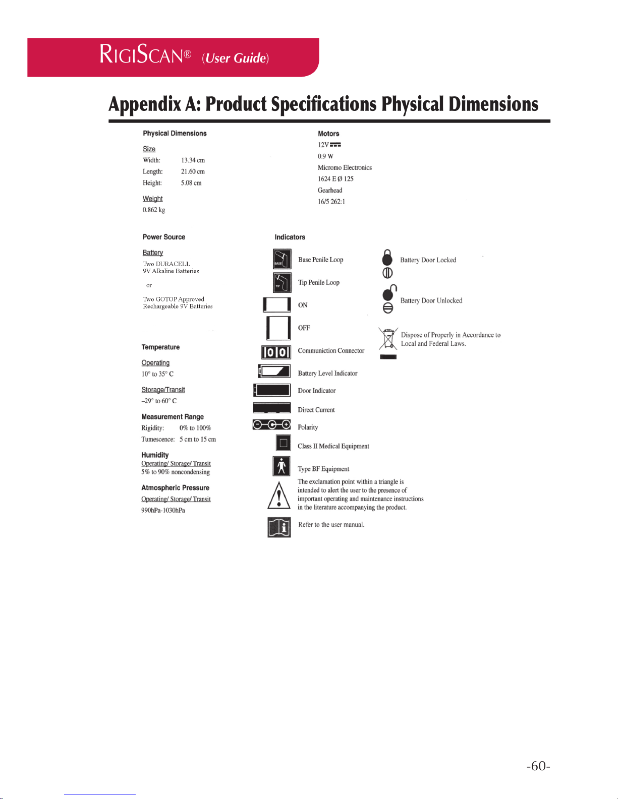
-60-
Appendix A: Product Specications Physical Dimensions
RIGISCAN
®
(User Guide)
Page 61
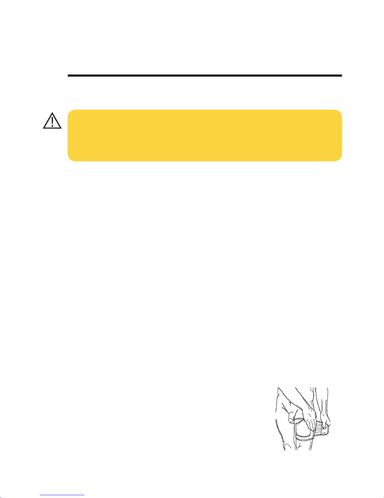
-61-
Patient Instruction Sheet
Warning! The RigiScan Plus System is for use only on order of a licensed physician.
Warning! DO NOT turn on the RigiScan Plus Monitor until you have placed the loops on your
penis. Doing so may result in penile pain, irritation or bruising.
Warning! DO NOT remove or loosen cables from the RigiScan Plus Monitor. If the cables are
not rmly connected to the monitor, patient injury may result from over tightening of
the loops.
Warning! DO NOT use the RigiScan Plus System if the loops or connecting cables are worn or
damaged in any way. Doing so may result in patient injury from over tightening of the
loops.
Warning! DO NOT engage in any sexual activity, such as intercourse, oral sex or masturbation
during RigiScan testing. Doing so may result in patient injury or erroneous data.
Warning! DO NOT bath or shower while wearing the RigiScan Plus Monitor. Getting the monitor
wet could cause electrical shock or damage to the monitor.
Warning! Turn off the RigiScan Plus Monitor before urinating. Urinating with the monitor on may
cause pain, irritation or blood in the urine.
Warning! DO NOT use electric blankets, electric razors, power tools, microwave ovens, hair dryers
or cellular phones while operating the RigiScan Plus System. These appliances may
interfere with operation of the monitor or cause erroneous recordings.
Putting on the RigiScan Plus Monitor
Stand comfortably. Wrap the leg strap (supplied in the carrying case)
around the thigh of either leg with the pocket opening toward your penis
(see Figure B-1). If you sleep on your left side, attach the strap to your left
thigh, and if you sleep on your right side, attach the strap to your right
thigh. The strap should be comfortably snug.
Fig. B-1
Appendix B: Patient Instructions
The following pages lists instructions for the patient to follow in the use of the RigiScan Plus Monitor.
Provide these instructions in order to send home with patients.
WARNING: It is the responsibility of the physician to assure that adequate instructions and
orientation regarding in-home use of the RigiScan Plus Monitor are given to the patient. These
instructions are provided as a reference only and are not intended to replace the instructions
given by the physician. Inadequate instruction may result in patient injury.
Page 62
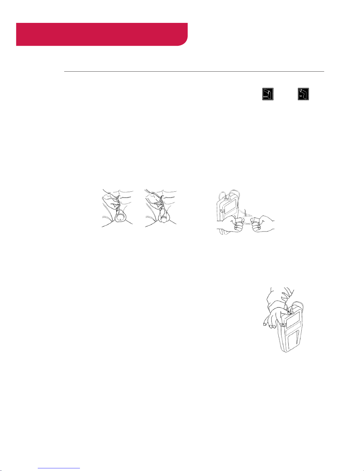
-62-
RIGISCAN
®
(User Guide)
Slide the RigiScan Plus Monitor in the leg strap pocket.
The loops are labeled on the wide end of the RigiScan Plus Monitor as BASE and TIP . The
Base Loop has the blue end and the Tip Loop has the white end. Place the Base Loop around your
penis approximately 1/4” (6 mm) from the base of your penis. Place the Tip Loop around the end of
your penis about 1/4” (6 mm) from the glans or head of your penis (see Figure B-2). You may have to
stretch your soft penis to place the loops properly. If the loops are too small to let you put them on
comfortably, insert two ngers into the loop and gently pull outward to widen them (see Figure B-3).
The RigiScan Plus Monitor will adjust the loops when it is turned on.
Starting a RigiScan Plus Session
To turn the RigiScan Plus Monitor on, press the on/off button until it
clicks and the button stays in. To turn off the RigiScan Plus Monitor, press
the on/off button until it clicks and pops out (see Figure B-4). The RigiScan Plus Monitor will beep once when activated the rst night, twice
the second night, and three times the third night. Once you have the
RigiScan Plus Monitor and loops in place, hold the loops while you turn
on the RigiScan Plus Monitor to make sure the loops stay in place on
your penis. Once the RigiScan Plus Monitor is turned on, the base loop,
followed by the tip loop, will slowly become smaller to t snugly around
your penis. Once the unit has adjusted the loops, you can let go of them.
The loops will squeeze gently around your penis every 15 seconds and
will continue through the full session (up to ten hours). This is how the RigiScan Plus Monitor measures
your erections. You may wear loose pajamas over the RigiScan Plus Monitor, however, be careful not
to kink or bend the cables sharply. To interrupt the session for any reason, such as using the toilet, press
Fig B-4 Turning on the
RigiScan Plus monitor.
Fig. B-2 Placing the Base and
Tip Loops
Fig. B-3 Widening the
Loops
Page 63
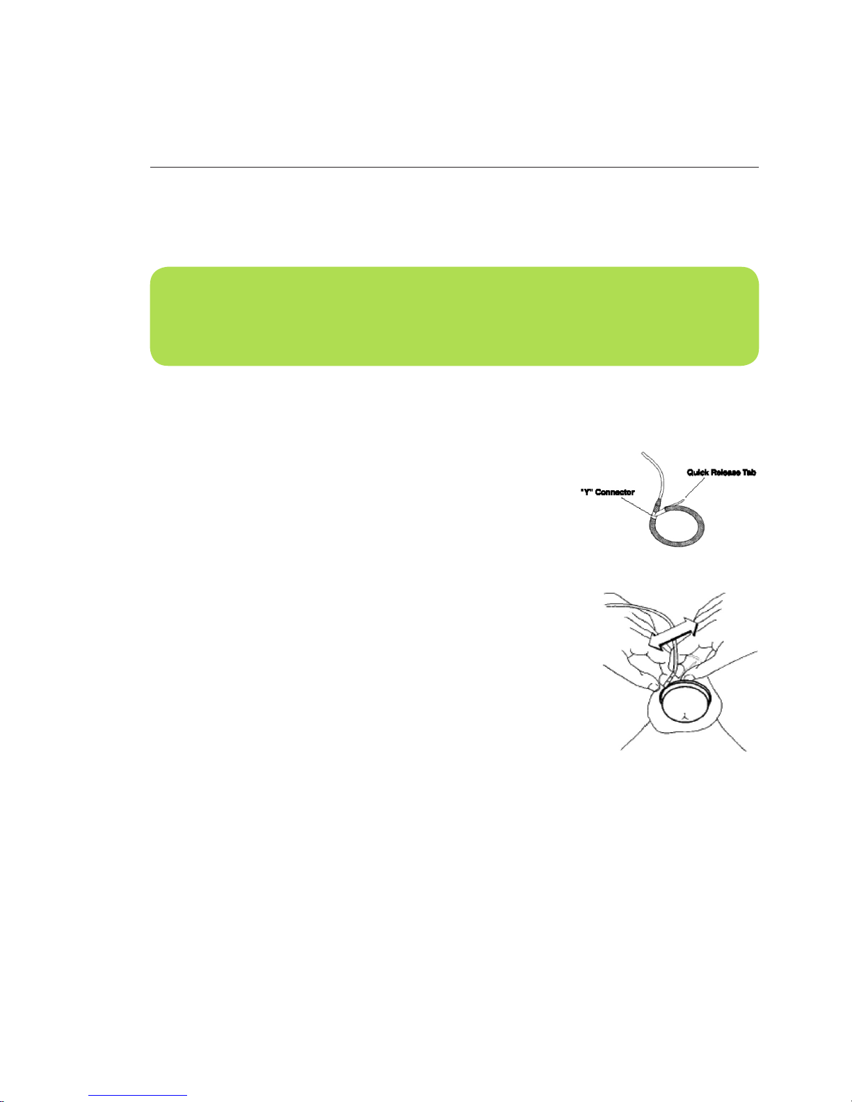
-63-
the on/off button to turn off the RigiScan Plus Monitor. You can leave the monitor off for up to fteen
minutes. Be sure to hold the leg strap and monitor in place when standing or walking. When you are
ready to go back to sleep, turn the monitor on again.
Removing the Loops Quickly
Normally, you would remove the loops by inserting your ngers
gently into the loops and pulling outward to expand the loops as
shown in Figure B-3. However, if you experience pain during testing
or want to remove the loops quickly for any other reason, you can
unsnap the loops with the quick release tab. To do this, follow these
steps (see Figures B-5A and B-5B).
1. With one hand, grasp the loop at the “Y” connector.
2. With the other hand, grasp the quick release tab and pull it
sharply until the two ends of the loops come apart.
Fig. B-5B Removing the Loops
quickly
Fig. B-5A
NOTE: You may leave the loops in position when urinating, but remember to turn off the Ri-
giScan Plus Monitor before urinating. Hold the leg strap and monitor in place when standing or
walking. Make sure to turn the monitor back on within fteen minutes.
Page 64
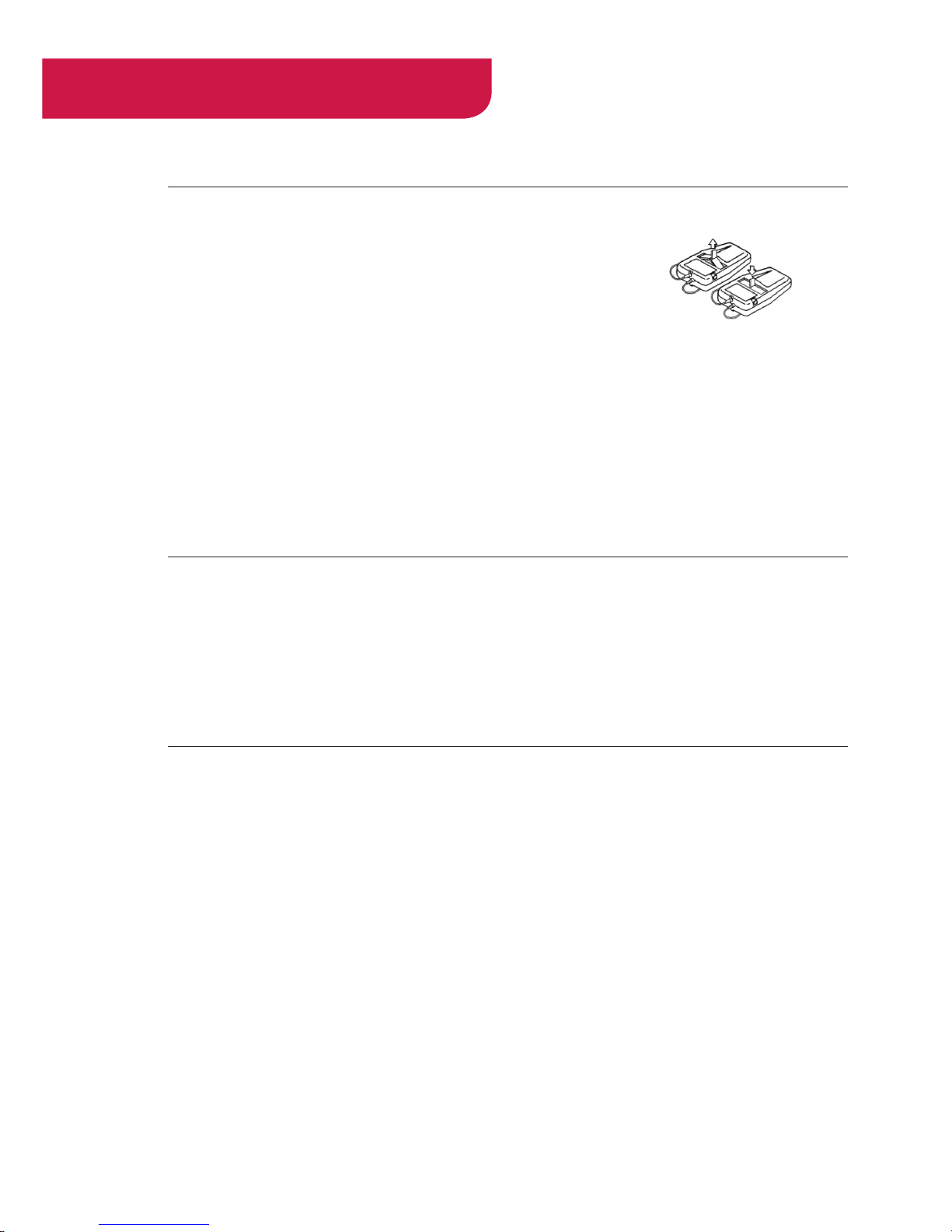
-64-
RIGISCAN
®
(User Guide)
When you Wake the Next Morning
When you wake the next morning rst turn off the RigiScan Plus
Monitor.
Ease the loops off your penis by gently inserting your ngers into
the loops and pulling slightly outward to widen them.
Remove the RigiScan Plus Monitor from the leg strap pocket and
remove the leg strap from your leg. To replace the batteries, open
case. Place the strap and RigiScan Plus Monitor back in the carrying case.
REMEMBER! If you have any questions, do not hesitate to contact your doctor’s ofce. Replace/
recharge the batteries before each evening’s session. If using alkaline batteries, fresh batteries are
supplied in the carrying case. Dispose of used alkaline batteries in accordance with applicable
regulations. If using rechargeable batteries, place them into the approved battery charger so they are
fully charged for the next session. Remove the old batteries by pulling on the black ribbon between
the two batteries, and insert new batteries as indicated by the image inside the battery cavity. (see
Figure B-6)
Fig. B-6 Replacing the
Batteries
Page 65

-65-
Appendix C: References
1. Frohrib DA, Goldstein I, Payton TR, Padma-Nathan H, Krane RJ : Characterization of penile
erectile states using external computer-based monitoring. J. Biomedical Engineering 1987,
Mai, 109, p 110.
2. Kaneko S, Bradley WE : Evaluation of erectile dysfunction with continuous monitoring of
penile rigidity. J. Urol. 1986, No. 136, 1026.
3. Bradley WE : New techniques in evaluation of impotence. Urology. 1987, Avril, 29(4), p 383.
4. Giesbers AAGM, Bruins JL, Kramer AEJL, Jonas U : New methods in the diagnosis of
impotence : RigiScan penile tumescence and rigidity monitoring and diagnostic papaverine
hydrochloride injection. World J. Urol. 1987, 5(175), p 176.
5. Kessler WO : Nocturnal penile tumescence. Urologic Clinics of North Am. 1988, Fév., 15(1),
p 81.
6. Lakin MM, Montague DK : Intracavernous injection therapy in postpriapism cavernosal
brosis. J. Urology 1988, Oct., 140, p 828.
7. Weinberg JJ, Badlani GH : Utility of RigiScan and papaverine in diagnosis of erectile
impotence. J. Urology 1988, Juin, 31(6), p 526.
8. Zeidman J, Raz S, Ehrlich RM : Spurious impotence after hypospadias repair. Urology. 1989
Avril, 33(4), p 300.
9. Burris AS, Banks SM, Sherins RJ : Quantitative basement of nocturnal penile tumescence and
rigidity in normal men using a home monitor. J. Adrol. 1989, Nov./Déc., 10(6), p 492.
10. Fein RL : Classication of sexual dysfunction for management of intracavernous medication-in
duced erections. J. Urol. 1990, Fév., 143, p 298.
11. Montague DK, Lakin MM, Vanderbrug Mendendorp S, Tesar LJ : Infusion pharmacocaverno
sometry and nocturnal penile tumescence ndings in men with erectile dysfunction. J. Urol.
1991, Avril, 145, p 768.
12. Levine LA, Carroll RA: Nocturnal penile tumescence and rigidity in men without complaints
of erectile dysfunction using new quantitative analysis software. J. Urol. 1994, October,
152(4), p 1103.
Page 66
-66-
RIGISCAN
®
(User Guide)
Appendix D: Electromagnetic Declaration
Notes and Cautions
This symbol means: Attention, consult accompanying documents.
This symbol indicates Type BF equipment.
CAUTIONS:
This device is not intended for use in the presence of ammable mixtures.
This device requires special precautions regarding EMC and needs to be installed and
put into service according to the EMC information provided in the accompanying
documents.
This device may be affected by portable and mobile RF communications equipment.
This device should not be used adjacent to or stacked with other equipment and that if
adjacent or stacked use is necessary, the RigiScan should be observed to verify normal
operation.
NOTE ON CLASSIFICATION:
This device is classied as internally powered.
This device is classied Type BF equipment for protection against electrical shock.
This device is classied as ordinary equipment without protection against ingress of water.
This device is classied as suitable for continuous operation
NOTE ON DISPOSAL:
This device contains electronic components and should be disposed of according to
local, state and national regulations. Please contact your local authorities for proper
disposal of small electronics devices. Remove batteries and recycle them according to
regulations as well. Many retail outlets that sell batteries provide for free recycling.
Page 67
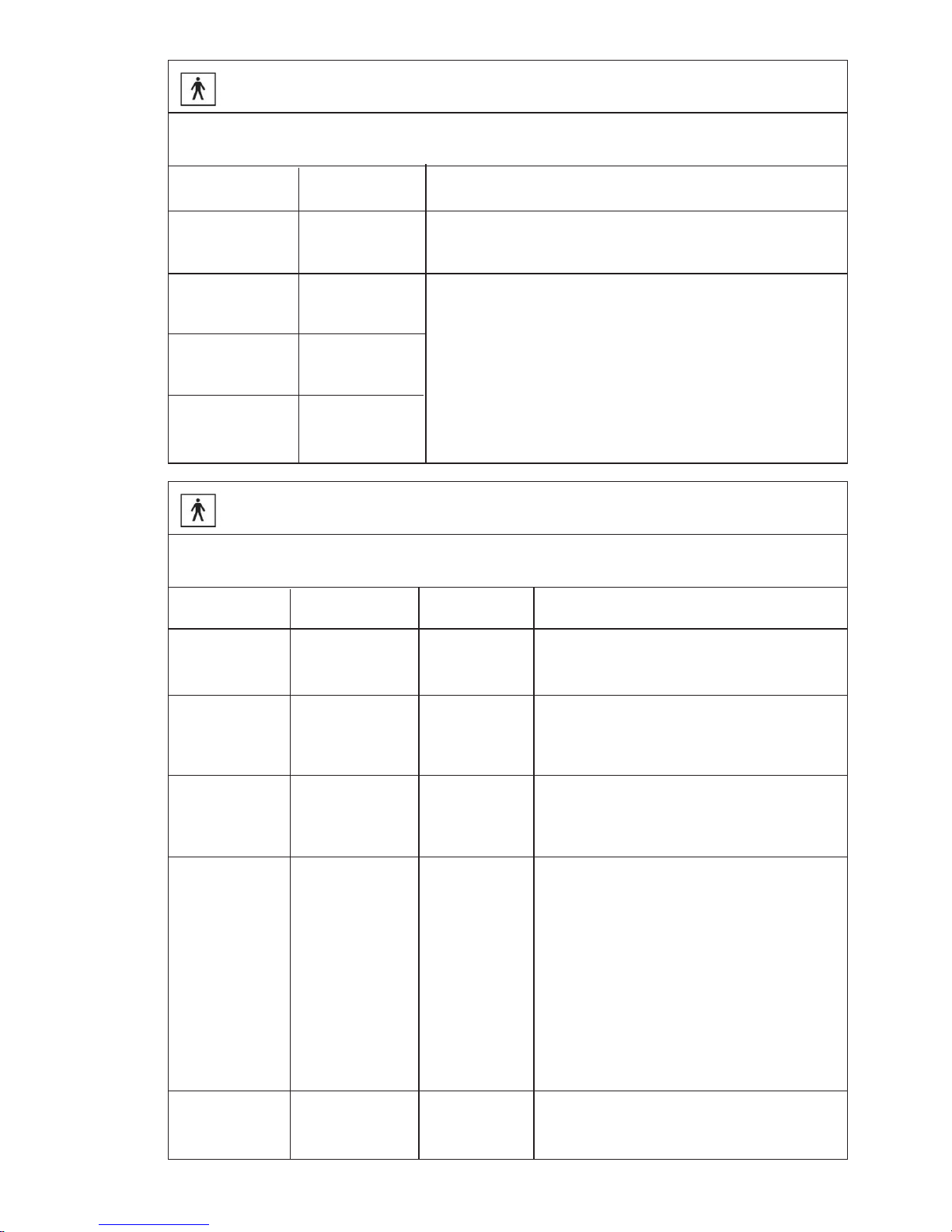
-67-
Guidance and manufacturer’s declaration - electromagnetic emissions
The RigiScan is intended for use in the electromagnetic environment specied below. The customer or the user of
the RigiScan should assure that it is used in such an environment.
Emissions
Test
RF emissions
CISPR 11
The RigiScan uses RF energy only for its internal function. Therefore, its
RF emissions are very low and are not likely to cause any interference
in nearby electronic equipment.
The RigiScan is suitable for use in all establishments, including domestic
establishments and those directly connected to the public low-voltage
power supply network that supplies buildings used for domestic purposes.
Group 1
Group B
TBD
TBD
RF emissions
CISPR 11
Harmonic
IEC 61000-3-2
Voltage uctuations/
icker emissions
IEC 61000-3-3
Compliance Electromagnetic environment — guidance
Guidance and manufacturer’s declaration - electromagnetic immunity
The RigiScan is intended for use in the electromagnetic environment specied below. The customer or the user of
the RigiScan should assure that it is used in such an environment.
IMMUNITY test
Electrostatic
discharge (ESD)
IEC 61.000-4-2
Electrical fast
transient/burst
IEC 61000-4-4
Power frequency
(50/60 Hz) magnetic
eld IEC 61000-4-8
Surge
IEC 61000-4-5
Voltage dips, short
interruptions and
voltage variations
on power supply
input lines
IEC 61000-4-11
± 6 kV contact
± 8 kV air
3 A/m 3 A/m
±2 kV for power
Supply lines
± 1 kV for
input/output lines
± 1 kV line(s) to
line(S)
± 2 kV line(s) to earth
<5 % (IT
(>95 % dip in UT)
for 0,5 cycle
40 % UT
(60 % dip in U-1)
for 5 cycles
70 % (IT
(30 % dip in UT)
for 25 cycles
<5 % UT 180°
(>95 % dip in UT)
for 0.5s
<5 % (IT
(>95 % dip in UT)
for 0,5 cycle
40 % UT
(60 % dip in U-1)
for 5 cycles
70 % (IT
(30 % dip in UT)
for 25 cycles
<5 % UT 180°
(>95 % dip in UT)
for 0.5s
± 1 kV line(s) to
line(S)
± 2 kV line(s) to
earth
±2 kV for power
Supply lines
± 1 kV for
input/output lines
Compliance
Electromagnetic environment
– guidance –
Floors should be wood, concrete, or ceramic tile. If
oors are covered with synthetic material, the relative
humidity should be at least 30 %.
Mains power quality should be that of a typical
commercial or hospital environment.
Mains power quality should be that of a typical
commercial or hospital environment.
Mains power quality should be that of a typical
commercial or hospital environment. If the user of the
RigiScan requires continued operation during power
mains interruptions, it is recommended that the
RigiScan be powered from an uninterruptible power
supply or a battery.
Power frequency magnetic elds should be at levels
characteristic of a typical location in a typical commercial or hospital environment.
Page 68
-68-
RIGISCAN
®
(User Guide)
NOTE 1 At 80 MHz and 800 MHz, the higher frequency range applies.
NOTE 2 These guidelines may not apply in all situations. Electromagnetic propagation is affected by absorption and reec-
tion from structures, objects, and people.
a Field strengths from xed transmitters, such as base stations for radio (cellular/cordless) telephones and land mobile radios, amateur radio, AM and FM radio broadcast and TV broadcast cannot be predicted theoretically with accuracy. To assess
the electromagnetic environment due to xed RF transmitters, an electromagnetic site survey should be considered. If the
measured eld strength in the location in which the RigiScan is used exceeds the applicable RF compliance level above,
the RigiScan should be observed to verify normal operation. If abnormal performance is observed, additional measures
may be necessary, such as re-orienting or relocating the RigiScan. b Over the frequency range 150 kHz to 80 MHz, eld
strengths should be less than 3 V/m.
Guidance and manufacturer’s declaration - electromagnetic immunity
The RigiScan is intended for use in the electromagnetic environment specied below.
The customer or the user of the RigiScan should assure that it is used in such an environment.
IMMUNITY test
Conducted RF
IEC 61000-4-6
Radiated RF
IEC 61000-4-3
3 Vrms
150 kHz to 80 MHz
3 V
3 V/m
3 V/m
80 MHz to 2.5 GHz
IEC 60601
Test level
Compliance
level
Electromagnetic environment
– guidance –
Portable and mobile RF communications equipment
should be used no closer to any part of the RigiScan,
including cables, than the ‘recommended separation
distance calculated from the equation applicable to
the frequency of the transmitter.
Recommended separation distance
d = 1.20
d = l .24P 80 MHz to 800 MHz
d = 2.30 800 MHz to 2.3 GHz
where Pis the maximum output power rating of the
transmitter in watts (W) according to the transmitter
manufacturer and d is the recommended separation
distance in meters (m).
Field strengths from xed RF transmitters, as determined by an electromagnetic site survey, a should
be less than the compliance level in each frequency
range. b Interference may occur in the vicinity of
equipment marked with the following symbol:
Page 69
-69-
Recommended separation distances between
portable and mobile RF communications equipment and the RigiScan
The RigiScan is intended for use in an electromagnetic environment in which radiated RF disturbances are con-
trolled. The customer or the user of the RigiScan can help prevent electromagnetic interference by maintaining a
minimum distance between portable and mobile RF communications equipment (transmitters) and the RigiScan as
recommended below, according to the maximum output power of the communications equipment.
Rated maximum output
power of
150 kHz to 80 MHz
W
Separation distance according to frequency of transmitter
m
150 kHz to 80 MHz
d= 1 . 2 P
0.01
0.1
1
10
100
0.12m
0.38m
1.2m
3.8m
12m
0.12m
0.38m
1.2m
3.8m
12m
0.23m
0.76m
2.3m
7.6m
23m
80 MHz to 800 MHz
d = 1.2 P
800 MHz to 2.5 GHz
d = 2.3 P
For transmitters rated at a maximum output power not listed above, the recommended separation distance d in meters
(m) can be estimated using the equation applicable to the frequency of the transmitter, where P is the maximum
output power rating of the transmitter in watts (W) according to the transmitter manufacturer.
NOTE 1 At 80 MHz and 800 MHz, the separation distance for the higher frequency range applies.
NOTE 2 These guidelines may not apply in all situations. Electromagnetic propagation is affected by absorption and
reection from structures, objects, and people.
Page 70
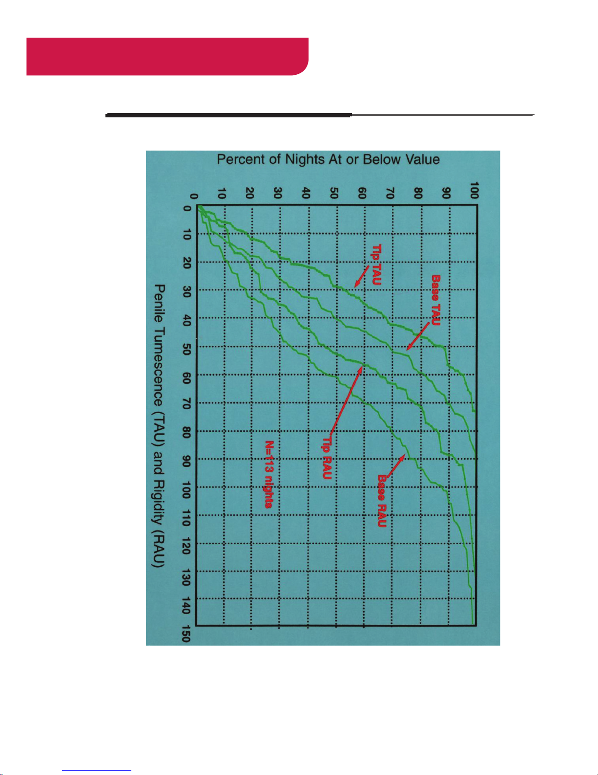
-70-
RIGISCAN
®
(User Guide)
Appendix E: RigiScan Nomogram
Page 71

-71-
RIGISCAN® PLUS SYSTEM AND ACCESSORIES
A. This limited warranty applies only to the hospital or physician (hereinafter referred to as “CUSTOMER”)
purchasing the RigiScan Plus System from GOTOP Medical , Inc.
This is limited warranty assured the CUSTOMER the GOTOP Medical, Inc. will replace or repair any RigiScan
System which malfunctions in the course of normal operations within one year from the date of invoice due to
defects in parts or workmanship. Ancillary components, consumable, computer support equipment or peripherals
are not warranted by GOTOP Medical.
B. THE FOREGOING WARRANTY IS IN LEIU OF ALL OTHER WARRANTIES, EXPRESSED OR IMPLIED. INCULDING
WITHOUT LIMITATION WARRANTIES OF MERCHANTABILITY AND FITNESS FOR ANY PURPOSE.
LIMITATIONS OF REMEDIES:
1. THE SOLE AND EXCLUSIVE REMEDY FOR GOTOP Medical, INC. AND LIABILITY OF ANY KIND INCLUDING
LIABILITY OR NEGLIGENCE WITH RESPECT TO PRODUCTS SHALL BE LIMITED TO THE REMEDY PROVIDED
IN THIS WARRANTY.
2. GOTOP Medical, INC. SHALL NOT BE LIABLE, IN ANY EVENT, FOR CONSEQUENTIAL OR SPECIAL DAMAGES
IN CONNECTION WITH SERVICE, PARTS AND LABOR HEREUNDER OR RESULTING FROM ANY USE OR
FAILURE INCLUDING, WITHOUT LIMITATION, LIABILITY FOR CUSTOMER’S EXPENSE OR LOSS OF INCOME
WHILE SYSTEMS ARE OUT OF OPERATION.
3. GOTOP Medical, INC. SHALL NOT BE LIABLE FOR ANY MEDICAL EXPENSES OR DAMAGES RESULTING
FROM THE USE OF THIS SYSTEM OR THE INTERPRETATION OF THE DATA CAUSED BY ANY FAILURE OR
MALFUNCTION OF THE PRODUCT.
To qualify for the remedy provided by this limited warranty, the CUSTOMER must meet the following conditions:
• The instruction for use in the RigiScan Plus Users Guide must be followed.
• No modication, adjustments, repairs or alteration shall have been made to any of the software, monitor, or
ancillary components supplied by GOTOP Medical, Inc.
A warranty determination cannot be made until repairs have been completed. Accordingly, the CUSTOMER
may be responsible for the cost of non-warranted service, parts and freight.
Upon determination of the nature and cause of the malfunction, GOTOP Medical, Inc. will issue a nocharge
invoice for services and parts covered by the warranty. Charges not covered by warranty will be invoiced to the
purchaser at the GOTOP Medical, Inc. current rates for labor and materials.
Examples of components not covered by this limited warranty include, but are not limited to:
• Monitor loop/cable replacements required due to normal wear and soiling.
• Monitor loop/cable replacements required due to improper disinfection techniques, physical damage,
and stains or stretching of the tension guides.
• Electronic components damage resulting form the uids inside the monitor.
• Communication cables, leg straps, carrying case, batteries, disk, AC/DC adapter
• Routine calibration of the monitor.
Address all questions regarding this warranty to a GOTOP Medical, Inc. Service Representative at 651-641-3621
Appendix F: Limited Warranty
Page 72
-72-
RIGISCAN
®
(User Guide)
NOTES:
Page 73

-73-
Page 74

All rights reserved. This material is protected under the International and Pan American Copyright Conventions.
It may not be reproduced in whole or in part without written permission from the publisher. Adaptation or any other form of copyright
infringement by any individual, rm, organization or other entity will not be tolerated by the publisher of this work.
Copyright ©2016 by GOTOP Medical, Inc. Printed in the United States of America
GOTOP Medical, Inc.,
1000 Westgate Drive, Suite 125,
St. Paul, MN 55114
U.S.A.
P 651.641.3621
F 651.641.3622
www.gotopmedical.com
PL09-0030 Rev D 08/16
 Loading...