

Page 1

Gotharman’s Tiny LD
Picture shows a proto type, and will be replaced as soon as the final model is ready.
Granular Workstation
User Manual V10.26
1
Page 2

Content Of This Manual
Introduction 9
Very Special Thanks To 11
In The Box 12
Getting Started 13
User Interface 19
Preset Select Screen 22
Operating Tiny LD 26
Trigger synth/sampler parts manually 26
Starting/stopping Sequencer 27
Selecting a Part/Track 28
Selecting Effects Processors 28
Note Tracks Steps view/edit 29
Mute/Unmute Note Tracks 30
Copy Morph Layer A to B 31
Panic 31
Compare Preset 32
Exit from any page 33
Shortcut to Save Preset 33
Upper and Lower Parameter Rows 34
Audio Bus System 35
Tiny LD Structure 36
2
Page 3

Synth/Sampler Parts 37
Modulation Sources 38
Accessing The Synth Part Pages 45
Editing The Parameters 47
Parameters Randomizer 48
Trigger Setup 50
Zone Setup 52
Audio Bus Setup 53
Oscillator/Sampler/Noise 58
Granular Modulators 69
Random Generators 71
Digital Filters 72
VCA 81
Envelope 1 and 2 85
LFO 1 to 16 89
Audio Inputs Setup 92
Analog FilterBoard 93
Effects Processors 106
Insert Effects 1 to 8 108
List of Insert Effects 109
Insert Effects Select Page 111
Mix Modulation and Backwards 113
Chorus 115
Distortion 117
Bit Crush 119
Pitch Shifter 121
Resonator 124
Stretcher 126
FM 128
Glitch Shifter 1, 2 and 3 130
Pitch Shaper 132
FAT 134
Filters 136
Filters 2 139
Compressor 141
Expandor 143
PitchShaper2 145
Delays 148
Variator 150
3
Page 4

Time Stretch 152
Sample Pitch 154
Output Effects 1 and 2 156
List of Output Effects 157
Output Effects Select Page 159
Mix/Pan Modulation and Backwards 162
Delays 164
Granulator SQ 167
Variator 170
Reverb 172
Granulator (unsynced) 174
Xfade Granulator 177
Abstruct0 180
Time Stretch 183
Sample Pitch 185
4
Page 5

Sequencer 187
Entering The Sequencer 192
Sequencer Main 195
Clear Sequence 197
Note subtrack 198
Gate Time subtrack 201
Velocity subtrack 203
Position subtrack 205
Sub Position subtrack 207
Templates and Note Scales 209
Templates for Position subtrack 211
Note Track Mod page 213
Clear Note Track 215
Double Note Track 216
Realtime Recording of Notes 217
Step Recording of Notes 219
Track/Part Internal/External Operation 222
Audio Track Recording 225
Controller tracks 235
Controller Track templates 239
Controller Tracks CC page 241
Clear Controller Track 243
Double Controller Track 244
Controller Tracks Realtime recording 245
Recording Parameter Tweaks 248
Pitch Bend and CC recording auto setup 249
Controller Tracks Step Recording 251
Synth and Sequencer Morphing 252
5
Page 6

More… Parameters/Setup 253
Common Settings 256
Morph Setup 258
Common Settings 2 262
Initialize Preset 263
Parameter Snap Mode 264
FilterBoard Setup 265
FLASH Memory Check 266
Delete Sample Bank 267
Delete All Presets and Songs 268
C.P. 269
Preset/Song Mode 270
Display Update Rate 271
Save Preset 272
Song Mode 276
Accessing Song Mode 277
Song Edit page 281
Song Select page 283
Song Realtime Recording 285
Save Song 289
Initialize Song 293
Copy/Paste 295
Sample Record and Edit 298
Recording a Sampling 299
Edit a Sampling 306
Adjusting Start/End Points 308
Sample Chops 309
Wave Chop System 313
Deleting Last Recorded Sampling 321
Deleting Other Samplings 323
Graphical Sample Editing 324
Wave Builder 338
6
Page 7

USB 341
USB Sample Preview 343
Open A Directory 344
Importing Files 345
Importing Multiple Files 347
Reload Multiple Files 348
Import Samplings As Chops 350
Make a New Directory 353
Delete File From USB Drive 354
Export Samples, Presets and Songs 355
Updating Tiny LD Firmware 356
MIDI Specs 364
Parameters CC Control 366
Parameters CC numbers list 368
Effects parameters 1 and 2 371
Controlling Parameters From Controller Tracks 372
Safe Boot Mode 373
Installing Analog FilterBoard 374
7
Page 8

I hope that you will deform some great tracks
8
Page 9

Introduction
Thank you very much for purchasing/consider to purchase a Gotharman’s Tiny LD.
Tiny LD are a multi-timbral and polyphonic granular workstation with 16 parts. The granular
functions in it includes oscillator/sampler granular modulators and special granular effects.
Each of the 16 parts has a stereo oscillator/sampler, 2 filters with 16 different filter types, a stereo
VCA, 3 envelopes, 4 random generators and 2 granular modulators, a random one and a
sequenced one. Additional modulation sources includes 16 global LFO’s, 32 sequencer controller
tracks, 8 audio bus envelope followers, touch screen keyboard Y position and MIDI keyboard,
velocity, aftertouch, pitch bend and CC’s.
The samplers can hold up to 43 minutes of samplings/ maximum 2.048 samplings. Samplings can
be chopped by level peaks, wave zero points, or in equally sized slices. Up to 64 chop points are
possible for each sampling. Samples are stored in FLASH memory, and played back directly from
this, so: No loading times!
Each part can be send to up to two of 8 audio busses at the same time. Pan modulation can
control the send level to each of the 2 busses.
On the audio busses up to 8 insert effects and an analog filter can be placed, for processing the
sounds from the parts and from its audio inputs.
The output from the audio busses can be sent to any or both of the 2 audio outputs and to any or
both of the 2 output effect processors.
The 16 parts can be sequenced from a build-in sequencer, that has 16 note tracks, with up to 64
steps each, and 32 controller tracks, with up to 128 steps each. Each note track has a position
track, that makes it possible to alter the position of each step, making polyphonic step sequencing
and various direction modes possible. A sub position track is also available for micro timing.
Realtime, step time and xox style recording are possible. Knob movements and MIDI CC’s can be
recorded, both in realtime and step time on the controller tracks.
Both the note tracks and the controller tracks can also control external MIDI devices, with up to
128 notes of polyphony.
Audio tracks can be recorded on the note tracks. These can be instantly chopped for true
deforming manipulation.
9
Page 10

The sound generating parts, the LFO’s, the effects processors and the sequencer has 2 layers of
parameter settings, layer A and layer B, that can be independently adjusted, and morphed
between, using the Morph and Seq Morph knobs.
All the parameter settings can be stored in any of 1024 rewritable preset locations, and recalled at
any time.
1024 song locations are available, for programmed playback of presets, and for tracks mute
automation.
I hope that you will enjoy your Tiny LD for a long time, and deform a lot of great tracks.
10
Page 11

Very special thanks to:
Will be updated, when pre-ordering ends.
For supporting this project from the start. I sincerely appreciate your help.
11
Page 12

In The Box
In the Tiny LD box should be:
-Tiny LD itself
-A power supply –Multi plug –Works in most countries.
If any of these items are missing, please get in touch with Gotharman’s.
12
Page 13

Getting Started
Connecting:
On the right end panel of your Tiny LD, you will find the power switch, connection for power
supply, stereo audio outputs, and USB.
You would probably like to connect the audio outputs to a mixer or an amplifier, or anything else
that ends out in a speaker/a set of speakers. Since Tiny LD doesn’t have built in speakers, it just
needs to be connected to something, that can transfer its amazing sound to you. These should be
connected, using ¼” mono jack cables.
The left audio output (marked “AUDIO OUT L(hp)) doubles as a stereo headphone connector.
Please make sure that nothing is connected to the right audio output, when plugging headphones
into this connector.
13
Page 14

To the USB connector, a USB drive can be connected.
This should be:
-Maximum 32 GB
-FAT formatted
With a USB drive connected, you can:
-Import, export and back up samples as .wav files
-Import deFormer .lds samples
-Import, export and back up Tiny LD/LD3 presets and songs
-Update Tiny LD
-PLEASE NOTICE: The included factory samples CANNOT be exported. So if you want to keep these,
you should take care not to delete them. A USB stick with the factory samplings might be available
in the future.
To import a .wav file from another device, it must be:
-Mono or stereo
-44.1 KHz sample rate – Tiny LD will import other sample rates, but they will play back in a wrong
speed
-16 bit or 24 bit native PCM
-Standard wav’s or broadcast wav’s
14
Page 15

On the left end panel of your Tiny LD, you will find the stereo audio inputs and MIDI in and out.
Connect any line stereo/mono audio sources to the audio inputs, for sampling and/or processing
through Tiny LD’s effects and optional analog filter.
If the Tiny LD touch screen keyboard and step buttons seems a bit too limited, you might want to
connect a MIDI keyboard to MIDI in, in order to take full advantage of Tiny LD’s fully chromatically
playable sounds. It is also possible to connect anything that transmits a MIDI clock, if you would
like the sequencer of Tiny LD to sync to the rest of your setup.
On MIDI out, MIDI clock, MIDI CC’s from the Tiny LD edit knobs, and notes and CC’s from its
sequencer are transmitted. Connect any MIDI gear to this, that you would like to control from Tiny
LD.
15
Page 16

Starting Up
Connect the supplied power adaptor to the Power input, and to a 100V to 240V power source –
Usually a wall socket.
It’s a 9V, minimum 2.0A type with a 2.1 mm DC plug, with positive middle. The power supply on
the picture is only for reference. The actual one might look different.
Some Tiny LD’s might have been shipped out with a power adaptor, that has multiple tips. If you
have received one of these, you should use the tip with the blue ring, and make sure that the 2
parts are alligned to the text “Tip”:
Please look at the picture, on the next page….
16
Page 17

17
Page 18

Turn it on
Push the “I” on the power switch. Your Tiny LD should now turn on.
18
Page 19

The User Interface
Tiny LD has a highly sensitive and responsive capacitive touch display, 8 step/trigger/part
select/function buttons, a Func/Mute button, and a Steps/Parts 9-16 select/Part Select button. It
has 4 Edit Knobs for controlling and editing parameters and sending MIDI CC’s, that doubles as
Volume, Morph and sequencer Morph knobs. Only Edit Knob 4/Cut are assignable, to control
other parameters.
Pushing the Trigger 1-8 buttons, with Func/Mute and 9-16/Part unlit, will trigger the respective
Tiny LD part. Each trigger button will send a settable note number (Settable in the Synth “Trig””
section). When a trigger is trigged, the button will light up.
Pushing the Trigger 1-8 buttons, with Func/Mute unlit and 9-16/Part lighting up, will trigger the
respective Tiny LD part 9 to 16.
When on any of the sequencer pages, the trigger buttons works as steps on/off buttons. With the
9-16/Part button unlit, step 1 to 8 of the selected sequencer page, can be switched on and off, by
pushing the trigger buttons. With the 9-16/Part button lighting up, steps 9 to 16 of the same page
can be switched on and off.
19
Page 20

With the Func/Mute button lighting up, the functions written just below the steps/parts numbers
of the 8 trigger buttons, will ba active.
When the Func/Mute button is held down, it is possible to mute/unmute the 16 note tracks, by
pushing any of the 8 step buttons. If the 9-16/Part button is lighting up, part 9 to 16 will be
muted/unmuted.
When the 9-16/Part button is held down, the 8 step buttons functions as Part Select buttons.
Pushing any of these, will select part 1 to 8, if the 9-16/Part button is unlit, or part 9 to 16, if the 916/Part button is lighting up.
The 1/Volume knob adjusts the audio output volume, when located on the (Main) Preset Select
Page, and on the Main Synth Page. When located inside an edit page, it will adjust the first
parameter on the page. If the “Lowr” function is turned on, it will adjust parameter 5.
The 2/Morph (MIDI CC#1) knob morphs between synth layer A and B, when located on the (Main)
Preset Select Page, and on the Main Synth Page. When located inside an edit page, it will adjust
parameter 2 on the page. If the “Lowr” function is turned on, it will adjust parameter 6.
The 3/SeqMrp (MIDI CC#2) knob morphs between sequencer layer A and B, when located on the
(Main) Preset Select Page, and on the Main Synth Page. When located inside an edit page, it will
adjust parameter 3 on the page. If the “Lowr” function is turned on, it will adjust parameter 7.
The 4/Cut (MIDI CC#4) knob are adjusting the Cutoff frequency of digital filter 1 of the selected
part, unless it is assigned to modulate one or more parameters, when located on the (Main) Preset
Select Page, and on the Main Synth Page. When located inside an edit page, it will adjust
parameter 4 on the page. If the “Lowr” function is turned on, it will adjust parameter 8.
20
Page 21

The Touch Screen Keyboard
The Tiny LD display is touch sensitive. The touch interface is used for navigating through the edit
and settings pages, and in the bottom of most pages, a fully playable touch keyboard is present.
On the Preset and Song Select pages, it is, besides from playing notes on the touch keyboard, also
possible to apply modulation to the sound, by placing your finger on different positions between
the top and the bottom of the keyboard. This is referred to as Keyboard Y modulation. On any
other pages, the keyboard only plays notes.
The touch keyboard is always controlling the selected part.
It is possible to select the keyboard octave, by touching any of the 8 squares just above the
keyboard.
By touching the “-“ and “+” buttons, just above the keyboard, it is possible to adjust the keyboard
size. The size can be from 1 to 8 octaves.
The Y position modulation is transmitted, received and recorded as MIDI CC#16.
21
Page 22

The Preset Select Screen
This is the first screen you will see, right after Tiny LD ’s start-up screen, unless you left your Tiny
LD in Song mode, the last time it was turned off. Here you can change preset, jump to Tiny LD ’s
edit and settings pages, and adjust the touch keyboard settings, as described on the previous
pages.
On the top of this screen, the Sequencer bar/beat, that is currently being played back, is shown.
To the right of the bar/beat indicator, you will find a sequencer record indicator (REC) and a
sequencer tempo indicator. When the REC indicator is red, the sequencer are in record mode.
Touching the REC indicator, will switch the sequencer in and out of recording mode.
Touching the tempo indicator, will make Tiny LD jump to the sequencer main page, where you can
set the tempo. The tempo indicator will read “EXT”, if Tiny LD is set to external MIDI sync.
Below the bar/beat indicator, it says “Preset”, if Tiny LD is currently in preset mode, or “Song” if it
is currently in song mode.
Below this, the number and name of the currently selected preset/song is shown.
Below the preset name/number, you will find the touch screen keyboard.
Right above the preset name, 8 small VU-meters are shown. These shows the activity of voice 1 to
8.
22
Page 23

Touch the “EDIT” field in the upper right corner of the screen, to enter the edit and setup pages.
Touch the “PRESET” field, to select a memorized preset.
Selecting a preset:
Touch the “PRESET” field. A list of 5 presets near the currently selected preset, will now appear:
Touch “PREV” or “NEXT” to view the previous or next 5 presets, and finally touch the preset name
of the preset you would like to select. 1024 presets can be selected, from A01 to P64.
Tiny LD will now jump back to the main Preset Select screen, and show the name of the newly
selected preset.
If the sequencer is playing back, the Start/Stop LED will now start to flash, and the text “NEXT:”
will show right above the new presets name, awaiting track 1 to reach its start/end step. As soon
as this happens, Tiny LD will switch to the newly selected preset, the Start/Stop LED will stop
flashing, and “NEXT:” will dissapear.
If the sequencer is not playing back, Tiny LD will immediately switch to the new preset, when you
touch the preset name.
23
Page 24

When Tiny LD is turned off, it will remember which preset was selected, and start up with this,
when turned on again. It will also remember if it was in preset or song mode, and start up in the
same mode, and if it was in song mode, it will also remember which song was selected.
If you activate the PreView mode, by touching the PreView field, so it turns black with white text,
you can preview the presets, without Tiny LD jumping back to the main Preset Select screen.
If the sequencer is running, it will still wait for track 1 to reach step 1, until it jumps to the next
preset. This is indicated by the Start/Stop LED flashing.
24
Page 25

If any parameters of the preset has been edited, and the edits has not been stored, a “*” will
appear right between the preset number and the preset name.
When this appears, you will need to save your preset, in order to keep your edits.
Please see how to do this in the “Save Preset” section, later in this manual.
25
Page 26

Operating Tiny LD
Trigger the synth/sampler parts manually
To trigger synth/sampler parts 1 to 8 manually, make sure that neither the Func/Mute button or
the 9-16/Part button is lighting up, and then push any of the 8 trigger buttons, to trigger the
sounds that are programmed on each of these parts.
To trigger synth/sampler parts 9 to 16 manually, make sure that the Func/Mute button is not
lighting up, but push the 9-16/Part button, so this now is lighting up.
Now when you push any of the 8 trigger buttons, synth/sampler parts 9 to 16 will be trigged.
26
Page 27

Starting and stopping the Sequencer:
To start the sequencer playback, push and release the Func/Mute button, so that it lights up.
Then push and release the 1/Play button, so that this lights up too. Now the sequencer is playing
back.
To stop the sequencer from playing back, make sure that the Func/Mute button is lighting up, and
push the 1/Play button, so that this is no longer lighting up. The sequencer has now been stopped.
If you, while the sequencer is playing back, push and release the Func/mute button, so that this is
no longer lighting up, trigger buttons 1 to 8 will light up, every time part 1 to 8 is trigged by the
sequencer. If you hit any of these trigger buttons, you will also trigger the part, and the button will
light up.
If you push the 9-16/Part button, so that this lights up, parts 9 to 16 will be shown on trigger
button 1 to 8.
27
Page 28

Selecting a part/track:
To select a synth/sampler part or a sequencer track for viewing/editing, push and hold the 916/Part button.
The selected part number will now be shown, by one of the 8 trigger buttons lightning up, if any of
the parts 1 to 8, is already selected. The number above the step button, is the part number that is
currently selected.
To select another part, while still holding down the Steps/Part button, push any of the 8 trigger
buttons.
To select synth/sampler parts 9 to 16 and sequencer tracks 9 to 16, before you push and hold the
9-16/Part button, push and release this one time, and make sure that it lights up. Then push and
hold it, to select part/track 9 to 16.
The selected part, is the part which parameters will be shown on the display, when entering the
edit pages.
Selecting a part, also selects the equally numbered Sequencer Note Track.
When entering the Sequencer Controller tracks 1 to 16, track 1 to 16 is selected in the same way.
When entering the Sequencer Controller tracks 17 to 32, 1 will equal 17, 2 will equal 18, and so on.
The Sequencer Controller tracks are selected separately from the parts.
Selecting Effects Processors
The 8 insert effects processors and the 2 output effects processors are also selected, using the
part select buttons.
Part 1 is insert effect 1
Part 2 is insert effect 2
Part 8 is insert effect 8
Part 9 is output effect 1
Part 10 is output effect 2
28
Page 29

Sequencer Note Track Steps view/edit:
First, select the part, for which you would like to view/edit the note steps, as described earlier in
this manual. You can, of course, select another part at any time, also after you have entered note
step edit mode.
To enter note step edit mode, simply enter any of the Sequencer pages (described later in this
manual). Any note sequencer steps that are switched on to play back, will now also light up on the
8 step buttons.
With the 9-16/Part button not lighting up, steps 1 to 8 of the selected bar will be shown. With the
9-16/Part button lighting up, step 9 to 16 of the selected bar will be shown.
If the sequencer is running, the light state of each step button will be reversed, when a step is
playing back.
To switch a step on or off, simply hit the corresponding step button, and it will toggle its state.
When the sequencer are in recording mode (the Start/Stop button is flashing), pushing any of the
step buttons, will set record mode to step mode, and select this step for recording. The step
button will now flash.
When using the Tiny LD sequencer as a usual step sequencer, the steps will play back from left to
right. In this case, step 1 plays back at position 1, step 2 plays back at position 2 and so on.
On the Tiny LD sequencer, it is though possible to break this pattern, and make each step play
back on any position, using the position subtrack. It is even possible to make more steps playing
back at the same position, for polyphonic step sequencing. But more on that later in this manual…
Only 8 steps are shown at a time. The note tracks of Tiny LD has 64 steps. On the Sequencer pages,
described later in this manual, it is possible to switch which bar should be shown.
29
Page 30

Mute/Unmute Note Tracks:
To mute, unmute or view the mute state of the 16 note tracks, push and hold the Func/Mute
button. If the 9-16/Part button is not lighting up, the state of part 1 to 8 is shown, if it is lighting
up, that state of part 9 to 16 is shown.
Unmuted tracks will now be shown by a step button that is lighting up, and shortly flashes off,
every time the track is triggering.
Muted tracks are shown by a step button that is unlit, and that lights up shortly, every time the
track would have triggered something, if it weren’t muted.
To mute or unmute a track, simply hit the corresponding step button, while still holding down the
Func/Mute button.
30
Page 31

Copy Morph Layer A to Layer B
Push and release the Func/Mute button, so that it lights up, to enter the function buttons. Now
push and release step button 5 (Copy), so that this also lights up. Instructions for copy and panic
will now be shown on the screen. Push and release step button 3 (Morph). Morph layer A synth
parts and sequencer parameters has now been copied to morph layer B. If you turn the Morph
knobs, you should now hear the same sound/sequence, no matter what position the knobs are in.
Panic
Push and release the Func/Mute button, so that it lights up, to enter the function buttons. Now
push and release step button 5 (Copy), so that this also lights up. Instructions for copy and panic
will now be shown on the screen. Push and release step button 8 (Exit).
Now all notes, both internally and on any MIDI devices connected to the Tiny LD MIDI out, will be
shutted off.
31
Page 32

Compare Edited Preset With Saved Preset
When you are editing a preset, and you would like to compare this with the originally saved
preset, this is possible, using the Compare function.
To listen to the previously saved preset:
-Push and release the Func/Mute button, so that it lights up.
-Push and release step button 5 (Copy).
-Push and release step button 7 (Save).
You can now play with the previously saved preset.
To de-active the Compare function, and jump back to the edited preset:
-Hit step button 7 (Save) again.
To de-activate the Compare function, and discard your edits:
-Hit step button 5 (Copy). The display will now show:
If you are absolutely sure, that you would like to discard your edits, hit step button 5 (Copy) again.
32
Page 33

Exit from any page
You can, at any time, exit from any menu page, using the hardware Exit button. Simply push and
release the Func/Mute button, so that it lights up, to enter the function buttons. Now push and
release step button 8 (Exit).
Exit and Esc (escape) touch buttons are also present on all menu pages, but sometimes a hardware
button is just better.
Shortcut to Save Preset
For a fast way to save your preset, so you don’t lose your settings, a shortcut to the Save Preset
pages was added. How to save a preset are explained later in this manual. To enter the save preset
pages, push and release the Func/Mute button, so that it lights up, to enter the function buttons.
Now push and release step button 7 (Save).
33
Page 34

Selecting upper and lower parameter rows
On most edit pages, there are 2 rows of parameters, an upper and a lower. Each row has 4
parameters. Since Tiny LD, unlike LD3, only has 4 edit knob, to edit these parameters, a function
that selects the upper and lower row is necessary.
To select the upper row:
Push and release the Func/Mute button, so that it lights up, to enter the function buttons. Now
make sure, that step button 4 (Lowr) is NOT lighting up.
To select the lower row:
Push and release the Func/Mute button, so that it lights up, to enter the function buttons. Now
push and release step button 4 (Lowr) so that this is lighting up.
This function is also used on the Sequencer step pages, for editing steps 5 to 8 and 13 to 16.
On naming pages, this is also used for selecting letter 5 to 8 and 13 to 16.
34
Page 35

Audio Bus System
Each of the 16 parts in Tiny LD, consists of a sound generator, that can be selected to be either a
multi waveform oscillator, a sampler or a noise generator. The audio signal from the sound
generator goes into 2 digital multimode filters. The output signal from the filters goes into a VCA.
In order to make the sound of the part audible, it must be assigned to one of the 8 audio busses.
The audio bus must also be sent to the audio outputs, or output effects processor 1 or 2.
In the VCA section of the part, it is possible to assign the selected part to output to one or two
audio busses. When outputting to two audio busses, the output signal from the part will be a
stereo signal, and one of the two digital filters will be placed on the left channel, and the other on
the right channel.
The default settings is that all parts are mono routed to Bus 1. Bus 1 is set to output on the main
Left and Right audio jack connectors.
On each of the 8 busses, it is possible to place any of the 8 insert effect processors and the analog
filterboard (if installed), for processing the sounds, that are sent to the busses.
Each audio input can also be routed to any Bus, for realtime processing of external gear through
the effects and analog filters.
The parameters of the audio busses, the parts and the effects are explained in the next section
“The Synth/Sampler Parts”.
The structure of the parts and busses in Tiny LD, are shown on the next page.
35
Page 36

36
Page 37

The Synth/Sampler Parts
Tiny LD has 16 parts, that is playing back through 8 stereo voices, using dynamic allocation.
Each part must be set up to output to one or two of the 8 audio busses (see the “Audio Bus
System” section earlier in this manual).
Each part has:
-1 oscillator. This can play a morphable synth waveform, up to 4 samplings (stereo or mono) or a
noise waveform.
-2 digital multimode filters with resonance.
-1 VCA, where both output level and pan can be adjusted and modulated.
-3 envelopes. Two ADSR types and one decay envelope.
-4 Random Generators. Always key trigged.
-2 Granular Modulators. A random one and a sequenced one. Both are trigged, when a synth
waveform or a sampling starts over.
Shared between the 16 parts:
-16 LFO’s with morphable waveforms.
Audio busses:
The audio output of the parts can be sent to any of 8 audio busses. Each part can output to 2
audio busses at a time.
On the audio busses effects and the analog filterboard can be applied, and the audio output of the
busses can be sent to the 2 output effects, and to the audio outputs.
Remember to save all edits you do in the synth/sampler section. Else they will be lost when you
change preset, or turn Tiny LD off. See how to in the ”Save Preset” section.
37
Page 38

List of Modulation Sources:
Env1: The output of ADSR Envelope 1
Env1-: The output of ADSR Envelope 1 Inverted
Env2: The output of Decay Envelope 2
Env2-: The output of Decay Envelope 2 Inverted
Aenv: The output of the VCA Envelope
Aenv-: The output of the VCA Envelope Inverted
LFO1: The output of LFO1
LFO1-: The output of LFO1 Inverted
LFO2: The output of LFO2
LFO2-: The output of LFO2 Inverted
LFO3: The output of LFO3
LFO3-: The output of LFO3 Inverted
LFO4: The output of LFO4
LFO4-: The output of LFO4 Inverted
LFO5: The output of LFO5
LFO5-: The output of LFO5 Inverted
LFO6: The output of LFO6
LFO6-: The output of LFO6 Inverted
LFO7: The output of LFO7
LFO7-: The output of LFO7 Inverted
LFO8: The output of LFO8
LFO8-: The output of LFO8 Inverted
LFO9: The output of LFO9
LFO9-: The output of LFO9 Inverted
LFO10: The output of LFO10
LFO10-: The output of LFO10 Inverted
LFO11: The output of LFO11
LFO11-: The output of LFO11 Inverted
LFO12: The output of LFO12
LFO12-: The output of LFO12 Inverted
LFO13: The output of LFO13
LFO13-: The output of LFO13 Inverted
LFO14: The output of LFO14
LFO14-: The output of LFO14 Inverted
LFO15: The output of LFO15
LFO15-: The output of LFO15 Inverted
38
Page 39

LFO16: The output of LFO16
LFO16-: The output of LFO16 Inverted
Rnd1: The output of Part Random Generator 1
Rnd1-: The output of Part Random Generator 1 Inverted
Seq1: The output of Sequencer Controller Track 1
Seq1-: The output of Sequencer Controller Track 1 Inverted
Seq2: The output of Sequencer Controller Track 2
Seq2-: The output of Sequencer Controller Track 2 Inverted
Seq3: The output of Sequencer Controller Track 3
Seq3-: The output of Sequencer Controller Track 3 Inverted
Seq4: The output of Sequencer Controller Track 4
Seq4-: The output of Sequencer Controller Track 4 Inverted
Seq5: The output of Sequencer Controller Track 5
Seq5-: The output of Sequencer Controller Track 5 Inverted
Seq6: The output of Sequencer Controller Track 6
Seq6-: The output of Sequencer Controller Track 6 Inverted
Seq7: The output of Sequencer Controller Track 7
Seq7-: The output of Sequencer Controller Track 7 Inverted
Seq8: The output of Sequencer Controller Track 8
Seq8-: The output of Sequencer Controller Track 8 Inverted
Seq9: The output of Sequencer Controller Track 9
Seq9-: The output of Sequencer Controller Track 9 Inverted
Seq10: The output of Sequencer Controller Track 10
Seq10-: The output of Sequencer Controller Track 10 Inverted
Seq11: The output of Sequencer Controller Track 11
Seq11-: The output of Sequencer Controller Track 11 Inverted
Seq12: The output of Sequencer Controller Track 12
Seq12-: The output of Sequencer Controller Track 12 Inverted
Seq13: The output of Sequencer Controller Track 13
Seq13-: The output of Sequencer Controller Track 13 Inverted
Seq14: The output of Sequencer Controller Track 14
Seq14-: The output of Sequencer Controller Track 14 Inverted
Seq15: The output of Sequencer Controller Track 15
Seq15-: The output of Sequencer Controller Track 15 Inverted
Seq16: The output of Sequencer Controller Track 16
Seq16-: The output of Sequencer Controller Track 16 Inverted
Seq17: The output of Sequencer Controller Track 17
Seq17-: The output of Sequencer Controller Track 17 Inverted
Seq18: The output of Sequencer Controller Track 18
Seq18-: The output of Sequencer Controller Track 18 Inverted
39
Page 40

Seq19: The output of Sequencer Controller Track 19
Seq19-: The output of Sequencer Controller Track 19 Inverted
Seq20: The output of Sequencer Controller Track 20
Seq20-: The output of Sequencer Controller Track 20 Inverted
Seq21: The output of Sequencer Controller Track 21
Seq21-: The output of Sequencer Controller Track 21 Inverted
Seq22: The output of Sequencer Controller Track 22
Seq22-: The output of Sequencer Controller Track 22 Inverted
Seq23: The output of Sequencer Controller Track 23
Seq23-: The output of Sequencer Controller Track 23 Inverted
Seq24: The output of Sequencer Controller Track 24
Seq24-: The output of Sequencer Controller Track 24 Inverted
Seq25: The output of Sequencer Controller Track 25
Seq25-: The output of Sequencer Controller Track 25 Inverted
Seq26: The output of Sequencer Controller Track 26
Seq26-: The output of Sequencer Controller Track 26 Inverted
Seq27: The output of Sequencer Controller Track 27
Seq27-: The output of Sequencer Controller Track 27 Inverted
Seq28: The output of Sequencer Controller Track 28
Seq28-: The output of Sequencer Controller Track 28 Inverted
Seq29: The output of Sequencer Controller Track 29
Seq29-: The output of Sequencer Controller Track 29 Inverted
Seq30: The output of Sequencer Controller Track 30
Seq30-: The output of Sequencer Controller Track 30 Inverted
Seq31: The output of Sequencer Controller Track 31
Seq31-: The output of Sequencer Controller Track 31 Inverted
Seq32: The output of Sequencer Controller Track 32
Seq32-: The output of Sequencer Controller Track 32 Inverted
Kybd: The last note number value received for the part
Kybd-: The last note number value received for the part Inverted
Velo: The last note velocity value received for the part
Velo-: The last note velocity value received for the part Inverted
Maft: The last mono aftertouch value received for the part
Maft-: The last mono aftertouch value received for the part Inverted
Bnd: The last pitch bend value received for the part
Bnd-: The last pitch bend value received for the part Inverted
Knb4: Edit knob 1 value or the last MIDI CC 4 value received
Knb4-: Edit knob 1 value or the last MIDI CC 4 value received Inverted
CC5: The last MIDI CC 5 value received
CC5-: The last MIDI CC 5 value received Inverted
40
Page 41

CC8: The last MIDI CC 8 value received
CC8-: The last MIDI CC 8 value received Inverted
CC9: The last MIDI CC 9 value received
CC9-: The last MIDI CC 9 value received Inverted
TouY: Touch screen keyboard Y-axis position
TouY-: Touch screen keyboard Y-axis position Inverted
GrRn: Granular Random Modulator
GrRn-: Granular Random Modulator Inverted
GrSq: Granular Sequenced Modulator
GrSq-: Granular Sequenced Modulator Inverted
CV1: The voltage applied to CV Input 1
CV1-: The voltage applied to CV Input 1 Inverted
CV2: The voltage applied to CV Input 2
CV2-: The voltage applied to CV Input 2 Inverted
CV3: The voltage applied to CV Input 3
CV3-: The voltage applied to CV Input 3 Inverted
CV4: The voltage applied to CV Input 4
CV4-: The voltage applied to CV Input 4 Inverted
Flw1: The Audio Bus 1 Envelope Follower
Flw1-: The Audio Bus 1 Envelope Follower Inverted
Flw2: The Audio Bus 2 Envelope Follower
Flw2-: The Audio Bus 2 Envelope Follower Inverted
Flw3: The Audio Bus 3 Envelope Follower
Flw3-: The Audio Bus 3 Envelope Follower Inverted
Flw4: The Audio Bus 4 Envelope Follower
Flw4-: The Audio Bus 4 Envelope Follower Inverted
Flw5: The Audio Bus 5 Envelope Follower
Flw5-: The Audio Bus 5 Envelope Follower Inverted
Flw6: The Audio Bus 6 Envelope Follower
Flw6-: The Audio Bus 6 Envelope Follower Inverted
Flw7: The Audio Bus 7 Envelope Follower
Flw7-: The Audio Bus 7 Envelope Follower Inverted
Flw8: The Audio Bus 8 Envelope Follower
Flw8-: The Audio Bus 8 Envelope Follower Inverted
CC10: The last MIDI CC 10 value received
CC10-: The last MIDI CC 10 value received Inverted
CC11: The last MIDI CC 11 value received
CC11-: The last MIDI CC 11 value received Inverted
CC12: The last MIDI CC 12 value received
CC12-: The last MIDI CC 12 value received Inverted
41
Page 42

CC7: The last MIDI CC 7 value received
CC7-: The last MIDI CC 7 value received Inverted
Trig: The trigger output of the part
Trig-: The trigger output of the part Inverted
Rnd2: The output of Part Random Generator 2
Rnd2-: The output of Part Random Generator 2 Inverted
Rnd3: The output of Part Random Generator 3
Rnd3-: The output of Part Random Generator 3 Inverted
Rnd4: The output of Part Random Generator 4
Rnd4-: The output of Part Random Generator 4 Inverted
CC17: The last MIDI CC 17 value received
CC17-: The last MIDI CC 17 value received Inverted
CC18: The last MIDI CC 18 value received
CC18-: The last MIDI CC 18 value received Inverted
CC19: The last MIDI CC 19 value received
CC19-: The last MIDI CC 19 value received Inverted
CC20: The last MIDI CC 20 value received
CC20-: The last MIDI CC 20 value received Inverted
CC21: The last MIDI CC 21 value received
CC21-: The last MIDI CC 21 value received Inverted
CC22: The last MIDI CC 22 value received
CC22-: The last MIDI CC 22 value received Inverted
CC23: The last MIDI CC 23 value received
CC23-: The last MIDI CC 23 value received Inverted
CC24: The last MIDI CC 24 value received
CC24-: The last MIDI CC 24 value received Inverted
CC25: The last MIDI CC 25 value received
CC25-: The last MIDI CC 25 value received Inverted
CC26: The last MIDI CC 26 value received
CC26-: The last MIDI CC 26 value received Inverted
CC27: The last MIDI CC 27 value received
CC27-: The last MIDI CC 27 value received Inverted
CC28: The last MIDI CC 28 value received
CC28-: The last MIDI CC 28 value received Inverted
CC29: The last MIDI CC 29 value received
CC29-: The last MIDI CC 29 value received Inverted
CC30: The last MIDI CC 30 value received
CC30-: The last MIDI CC 30 value received Inverted
CC31: The last MIDI CC 31 value received
CC31-: The last MIDI CC 31 value received Inverted
42
Page 43

CC33: The last MIDI CC 33 value received
CC33-: The last MIDI CC 33 value received Inverted
CC34: The last MIDI CC 34 value received
CC34-: The last MIDI CC 34 value received Inverted
CC35: The last MIDI CC 35 value received
CC35-: The last MIDI CC 35 value received Inverted
CC36: The last MIDI CC 36 value received
CC36-: The last MIDI CC 36 value received Inverted
CC37: The last MIDI CC 37 value received
CC37-: The last MIDI CC 37 value received Inverted
CC38: The last MIDI CC 38 value received
CC38-: The last MIDI CC 38 value received Inverted
CC39: The last MIDI CC 39 value received
CC39-: The last MIDI CC 39 value received Inverted
CC40: The last MIDI CC 40 value received
CC40-: The last MIDI CC 40 value received Inverted
CC41: The last MIDI CC 41 value received
CC41-: The last MIDI CC 41 value received Inverted
CC42: The last MIDI CC 42 value received
CC42-: The last MIDI CC 42 value received Inverted
CC43: The last MIDI CC 43 value received
CC43-: The last MIDI CC 43 value received Inverted
CC44: The last MIDI CC 44 value received
CC44-: The last MIDI CC 44 value received Inverted
CC45: The last MIDI CC 45 value received
CC45-: The last MIDI CC 45 value received Inverted
CC46: The last MIDI CC 46 value received
CC46-: The last MIDI CC 46 value received Inverted
CC47: The last MIDI CC 47 value received
CC47-: The last MIDI CC 47 value received Inverted
CC48: The last MIDI CC 48 value received
CC48-: The last MIDI CC 48 value received Inverted
CC49: The last MIDI CC 49 value received
CC49-: The last MIDI CC 49 value received Inverted
CC50: The last MIDI CC 50 value received
CC50-: The last MIDI CC 50 value received Inverted
CC51: The last MIDI CC 51 value received
CC51-: The last MIDI CC 51 value received Inverted
CC52: The last MIDI CC 52 value received
CC52-: The last MIDI CC 52 value received Inverted
43
Page 44

CC53: The last MIDI CC 53 value received
CC53-: The last MIDI CC 53 value received Inverted
CC54: The last MIDI CC 54 value received
CC54-: The last MIDI CC 54 value received Inverted
CC55: The last MIDI CC 55 value received
CC55-: The last MIDI CC 55 value received Inverted
CC56: The last MIDI CC 56 value received
CC56-: The last MIDI CC 56 value received Inverted
CC57: The last MIDI CC 57 value received
CC57-: The last MIDI CC 57 value received Inverted
CC58: The last MIDI CC 58 value received
CC58-: The last MIDI CC 58 value received Inverted
CC59: The last MIDI CC 59 value received
CC59-: The last MIDI CC 59 value received Inverted
CC60: The last MIDI CC 60 value received
CC60-: The last MIDI CC 60 value received Inverted
CC61: The last MIDI CC 61 value received
CC61-: The last MIDI CC 61 value received Inverted
44
Page 45

Accessing The Synth Part Pages
From the Preset/Song Select screen, Touch the “EDIT” field.
45
Page 46

Now Tiny LD will show the main Synth page:
In the top of the main Synth page, you will find the 6 main edit groups and the ESC (escape) touch
button. Touch any of these group buttons to access them, and touch ESC, to exit to the Preset
Select page.
The touch button of the currently selected edit group is brown/yellow, while the buttons of the
other groups are green.
The group of touch buttons, will be referred to as the “group select bar”.
Below the group select bar, you will find the synth blocks. Touch any block, to access the
parameters of it, and edit these. Part 1 to 16 is selected using the Steps/Part button in
combination with the step buttons and the 9-16/Part button.
In the bottom of this page, the touch keyboard is located.
46
Page 47

Editing The Parameters Of The Synth Part Blocks
Each edit page has up to 8 parameters, that can be edited. The parameters are shown on the
display as 8 parameter names, each with an alphanumeric value below them, that shows the
current value of the parameter.
When turning any of the 4 Edit Knobs, the corresponding parameter will be adjusted, and you will
hear a change in the sound, if the block is active. The 4 upper and lower parameters are selected,
using the Lowr function, explained under the “Operating Tiny LD” section, earlier in this manual.
Right below the parameters, you will find the subpage select touch buttons. Touch any of these, to
access the desired parameter sub page. The touch button that is black with white text, shows that
this is the currently selected sub page. The grey touch buttons, are the sub pages, that you can
select.
In the top of the display, it is, on the part edit pages, possible to see what part slot that is currently
selected.
In the upper right corner of each block you will find “EXIT”. Touch this to exit to the main Synth
page.
47
Page 48

The Synth Part Blocks
In this section of the manual, you will find a description of the parameters of each part, and the
parameters related to the LFO’s the effects processors and the BUS system.
The Synth Part Parameters Randomizer
If you should ever need some new inspiration for sounds, or if you just want to surprise yourself
with some sounds that you never even imagined, the Tiny LD parameter randomizer might be
exactly what you need.
To enter this, from the synth parts main page, touch RNDM.
48
Page 49

You should now enter this page:
Select the part that you would like to randomize, in the same way as you would usually select a
part, by pushing and holding the Steps/Part button, while pressing one of the 8 step buttons.
Switch the blocks on, that you would like to randomize, simply by touching these, adjust the
percentage, that it must maximum change the parameters, using Edit Knob 1, and hit “DO!”.
Green blocks are not randomized, brown blocks are.
Listen to the result.
If you like it, exit the randomizer page, and save the preset.
If you don’t like the result, hit “DO!” again, and keep hitting it, until something comes up, that you
like. Try with different percentage settings, and try to switch different blocks on and off.
When the Randomizer page is entered, all parameters are stored into a temporary buffer, that are
used for the randomization. So if you, for instance, first randomizes with 50%, and then with 20%,
the result will be maximum 20% away from the initial parameter settings, when the Randomizer
page was entered. It does not first randomize 50%, and then randomize 20% on top of that. To
randomize things further away, you must exit the Randomizer page, and re-enter it.
49
Page 50

Synth Part Trigger Setup
In this block, you can set up the poly mode of each part, the pitch bend range, the note that will
play pack, when pushing a trigger button, and if the part should be an internal or an external part.
From the synth parts main page, touch TRIG to enter this page.
Mode: Part polyphonic/monophonic mode. Choices are:
Poly: The part uses multiple voices, to play back polyphonically.
Voic1-8: Mono To Voice1-8. The part plays back monophonically, and only uses the
one voice, that it is assigned to. Other parts that are in poly mode, does not use this voice. It can
only be cutted off, by another part that is set to mono to the same voice.
Use this mode, when playing back long samples and audio tracks without chops, and if you got
some parts, that should cut each other off, like parts that are playing back closed and open hihats.
Vc1Lg-Vc8Lg: Mono To Voice1-8 with Legato Portamento. The same as Voic1-8
mode, but with legato portamento. If the portamento parameter on the Oscillator page is turned
up, the portamento effect will only be active, when notes are played overlapped.
50
Page 51

TriggerNote: C-1 to G9. The note that will play, when the step buttons are in trigger mode (when
both the Func/Mute button and the Steps/Part button are unlit), and you push the trigger button,
for this part. This is also the note that is sent via MIDI out, when a part is set to external, and you
hit the trigger button.
Trigger Note Modulation Source:
Any modulation source can modulate the trigger note. Only the positive modulation sources, can
be selected by the Edit Knob. To make a modulation source negative, touch the modulation source
parameter. For a complete list of modulation sources, see the list in the start of this section.
Mod: 0 to 512. Trigger Note Modulation amount
Bend Range: 0 to 12 notes. The global pitch bend range for all parts.
Chan: 1 to 16. The part output MIDI channel. This will also affect the part Sequencer Note Track.
When the part is set to external, this is the MIDI channel that note data played by the trigger
button, the touchscreen keyboard, on an attached MIDI device, and from the part sequencer note
track are sent on, to the Tiny LD MIDI out.
Int/Ext: Sets the part in internal (Int) or external (Ext) mode.
When a part is set to internal mode, all notes played by the part trigger button, the touchscreen
keyboard, on an attached MIDI device, and from the part sequencer note track, controls the
internal Tiny LD synth part.
When a part is set to external mode, all notes played by the part trigger button, the touchscreen
keyboard, on an attached MIDI device, and from the part sequencer note track, controls any MIDI
device, that is connected to the Tiny LD MIDI output, and that is set to the same MIDI channel, as
set by the Chan parameter on this page.
51
Page 52

Zone Setup
In this block, it is possible to set up a key zone and a MIDI channel for the part, that will take
effect, when Tiny LD is set in multi-timbral mode, and is controlled from an external MIDI device.
How to set Tiny LD in multi-timbral mode are explained later in this manual, in the MOR>Common
section.
From the synth parts main page, touch ZONE to enter this page.
LowK1: C-1 to G9. The lowest key of the part zone.
HiK1: C-1 to G9. The highest key of the part zone.
Trps1: -64 to +63. The incoming MIDI notes, inside the key zone, are transposed up(+) or down(-),
by the selected value.
Chan1: 1 to 16. The MIDI channel that will control this part.
52
Page 53

Audio BUS Setup
In this block, you will find the settings for the 8 audio busses. Please note that these settings are
not part specific, but global for the 8 busses and 16 parts.
From the synth parts main page, touch TRIG to enter this page.
Touch the Out touch button, to enter this first page, where you can select the output, which the
audio signal from each of the 8 busses, should be sent to.
Possibilities are:
L: The output of the Bus is sent to the left audio output.
R: The output of the Bus is sent to the right audio output.
L+R: The output of the Bus is sent to the left and the right audio outputs.
EFX1: The output of the Bus is sent to Output effect 1.
EFX2: The output of the Bus is sent to Output effect 2.
Off: The output of the Bus is not sent anywhere.
PLEASE NOTE: Audio busses that are assigned to be placed inside an output effect feedback loop,
will ignore this setting, and only output to the effect feedback input.
53
Page 54

Touch the Frl touch button, to enter this second audio Bus page, where it is possible to adjust the
release time of the envelope follower, that are attached to each audio Bus, and that affects the
output levels of these.
When this is set to 511, the follower will never decay. When set to lower values, the follower will
gradually decay, in accordance with the levels of the audio signal sent to it, from the synth parts.
The envelope followers are sent to the modulation system (Flw1 to Flw8), and can be selected as
modulation sources, for many parameters.
54
Page 55

Touch the Fga touch button, to enter this third audio Bus page, where it is possible to gain or
attenuate the level of the audio signal sent to the Bus envelope follower. At +0, there are no
gaining or attenuation. At positive values the signal to the follower is gained, at negative values,
they are attenuated.
55
Page 56
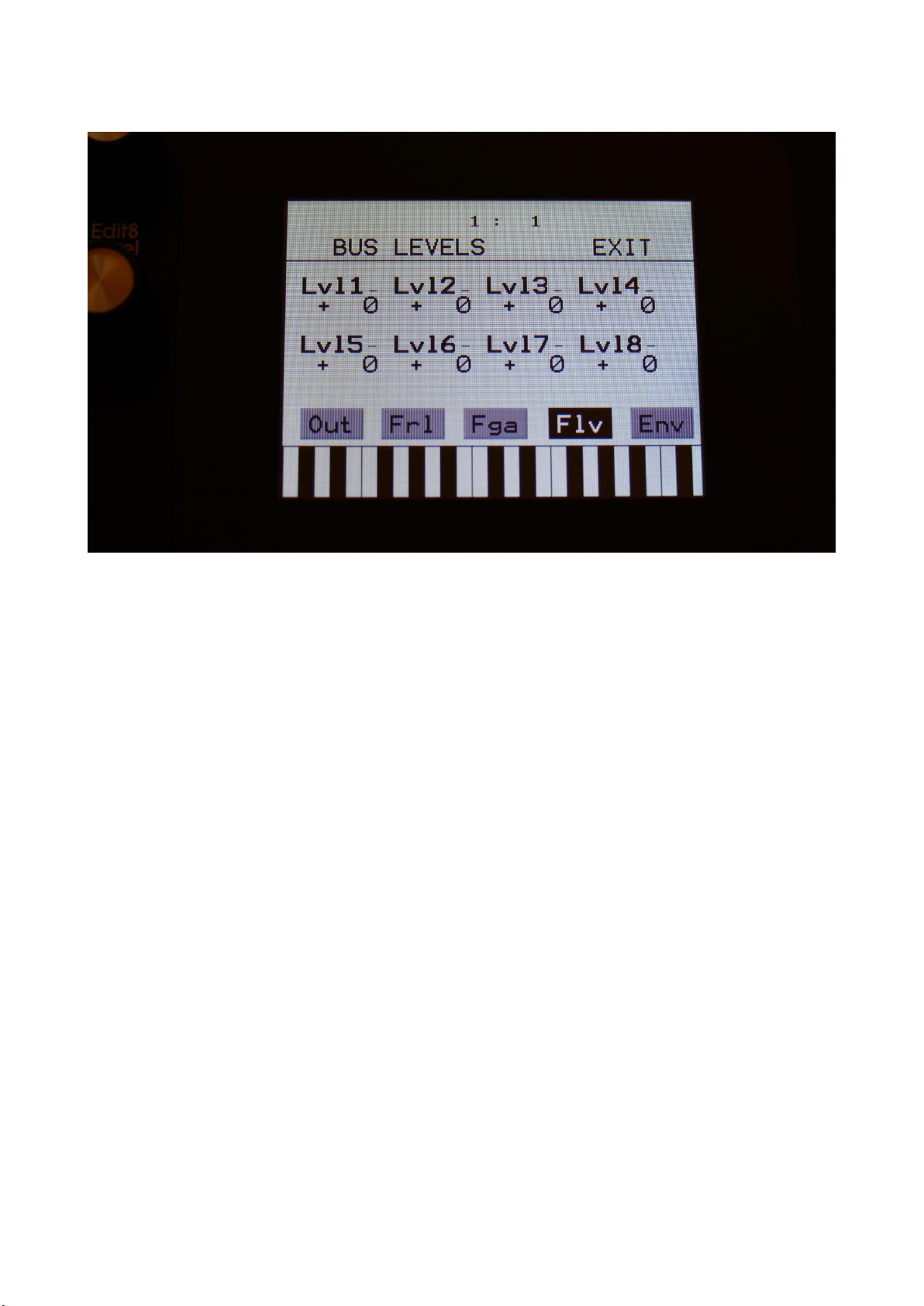
Touch the Flv touch button, to enter this fourth audio Bus page, where it is possible to adjust the
total output level of each Bus. Positive values will gain the output signal, negative values will
attenuate.
56
Page 57

Touch the Env touch button, to enter this fifth and last audio Bus page, where it is possible to
assign any of the 16 part VCA envelopes or the BUS Envelope Follower to control the Bus output
level. Here it is also possible to gain the Envelope Follower by x2 and x4.
As default, the un-gained Envelope Follower are assigned to control the BUS output level.
Each audio bus has their own Envelope Follower (8 Envelope Followers in total).
The possible settings are:
Flr: The BUS Envelope Follower will control the output level of the BUS.
1 to 16: The Part Envelope of the part that has the number you select here, will control the output
level of the BUS.
Fx2: The BUS Envelope Follower will control the output level of the BUS, and the signal of this will
be gained by x2.
Fx4: The BUS Envelope Follower will control the output level of the BUS, and the signal of this will
be gained by x4.
57
Page 58
Oscillator/Sampler/Noise Generator
In this block, you will find the settings for the part oscillator.
From the synth parts main page, touch OSC to enter this page.
The oscillator are the first block in the audio chain of a part. This is responsible for generating the
basic sound of each part, that can be modulated, filtered and effected, for shaping a sound.
A Tiny LD oscillator can be set to act as an oscillator, a sample player, a chopped keyboard sample
player, or a noise generator.
In oscillator mode it generates a waveform that is morphable between sine, triangle, saw, pulse
and feedback waves. Pulse width are adjustable for all waveform types. FM (frequency
modulation) is possible, with any audio bus as the modulation source. Pitch, PW, wave and FM
amount can be modulated. The pitch range of the oscillators are chromatically over the entire 10
octave MIDI keyboard range.
In sampler mode it plays back any of the 2.048 storable samplings, that can either be recorded on
Tiny LD itself in the Sample Rec section, or be imported in the USB section. Each part sampler has
4 sample slots, that each can contain one sampling. Switching between the 4 samplings is done via
the Chop parameter. Pitch, chop, start point and FM amount can be adjusted and modulated,
Length can be adjusted. Samples are chromatically tuned, and has a pitch range of 4 octaves above
58
Page 59

and 5 octaves below the original sample pitch. Loop mode can be set to Off, On, toggle, sustain,
off(unchopped) and on(unchopped).
In off and on modes, it will always use the sample chop point, if any.
In toggle mode, the looped sample playback will start, when you push and release a trigger button,
and stop when you push and release the same trigger button again.
In sustain mode, it will play the sampling back from the start point, until it reaches the second
chop point. Then it will loop back to the first chop point, and keep looping between these 2 points.
When importing a wav sampling with loop points set as cue points, these cue points are imported
to the first 2 chop points.
In off and on (unchopped) modes, the whole sampling will play back, ignoring any chop points.
It is possible to create chop points in the Tiny LD sample editor, and use these. Chops can be
detected by level peaks, by single wavecycles, and by dividing the sample length with a settable
number.
Chop points will also be imported from wav files, containing these as cue points.
In chopped keyboard sample mode, the chops of the selected sampling, will be spread over the
MIDI keyboard range.
The first chop will be placed at C2. Each chop will take up one key, and will not be tuned by the
keyboard. Tuning is only possible, using the Tune, Fine and pitch modulation parameters.
On the next key, after the last chop, the first chop will be placed, and the rest of the chops will be
repeated over the rest of the keyboard range.
If you set the #Smp parameter to 2 or 4, the Chop parameter on the OSC page, will select sample
1, 2, 3 and 4, to be laid out on the keyboard. Chop modulation will also switch between the 4
samplings.
If you select a sampling, that has no chops, the root key of this sampling, will be laid out over the
entire keyboard range.
In noise generator mode, the oscillator puts out a noise waveform. Pitch and pw (intensity) can be set and
modulated.
59
Page 60

Oscillator parameters
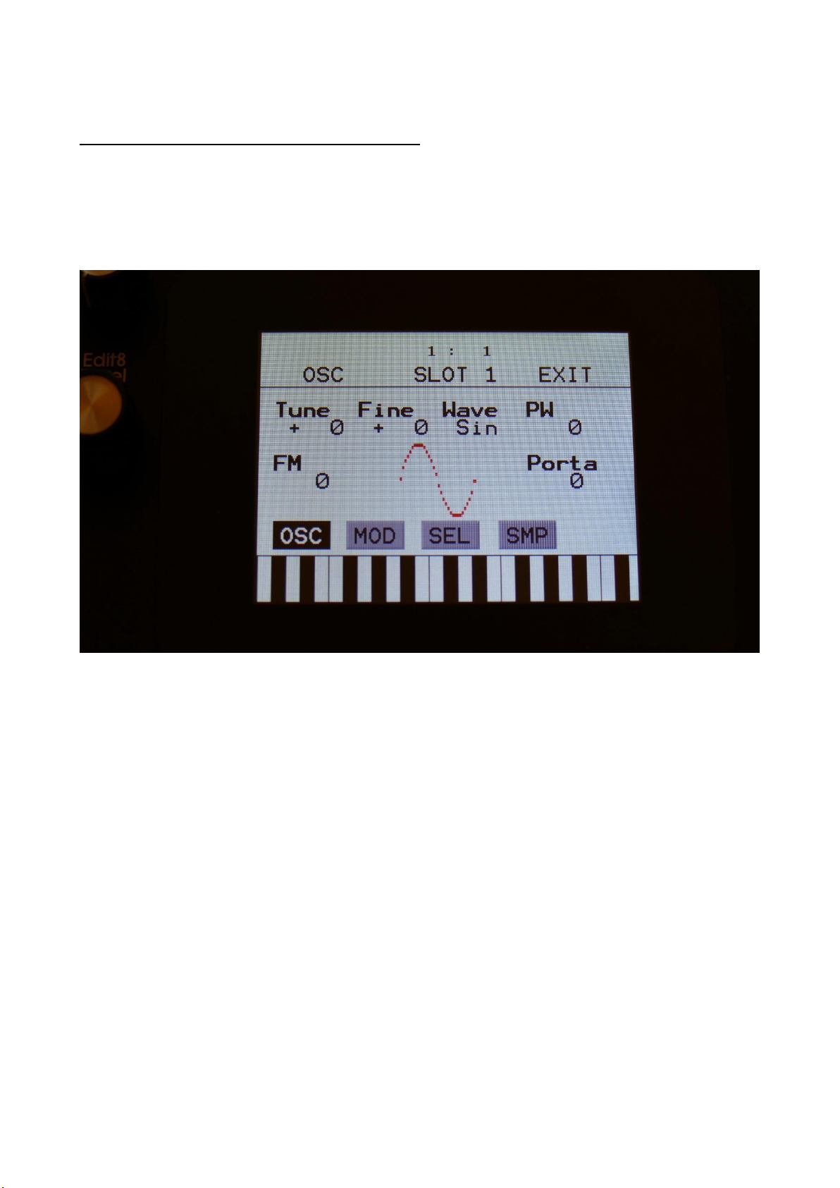
The OSC page, when in oscillator mode:
In the middle of the oscillator page, the currently generated waveform is shown.
Touch the buttons named OSC, MOD, SEL and SMP, to enter other oscillator pages, like
Modulation and oscillator/sampler/noise mode select.
Tune: Adjust the basic pitch in semitones. Range: -64 to + 63.
Fine: Fine tuning of the pitch. Range: -256 to +255.
Wave: This parameter lets you morph between sine, triange, saw, pulse and feedback waves.
PW: Adjusts the pulse width of the waveform. Unlike many other oscillator designs, the pulse
width can be adjusted on all of Tiny LD’s waveforms, not just the pulse wave.
FM: FM amount. The more this is turned up, the more a selected audio bus (in the SEL section) will
modulate the pitch of the oscillator. Range: 0 to 511.
Porta: Portamento. The more this is turned up, the slower the oscillator pitch will slide from one
note to another. Range: 0 to 511.
60
Page 61

The OSC page, when in Sampler and Chopped Keyboard mode:
In the bottom of the sampler page, the selected samplings waveform is shown in rough graphics.
When the sample, or part of it, is played back, the small black line below the waveform will show
the current playback point.
Tune: Adjust the basic pitch in semitones. Range: -64 to + 63.
Fine: Fine tuning of the pitch. Range: -256 to +255.
Start: The sample start point. Selects at what point the sample will start to play back, when it is
triggered. Range: 0 to 511, stretching over the whole sampling.
Length: Sets how much of the sampling should be played back. Range: 0 to 511, stretching over
the whole sampling.
61
Page 62

Loop: Sets the sampling loop mode.
Off: The sample will not loop, just play back one time from the adjusted, or chop selected, start to
end, and then stop. If the selected sampling has chop points, these will always be used.
On: The sample will play back from the adjusted start point, when triggered. When it reaches the
adjusted end point, it will loop back to the start point, and play back the sample over and over
again. If the selected sampling has chop points, these will always be used for the loop points.
Toggle: The looped sample playback will start, when you push and release a trigger button, and
stop when you push and release the same trigger button again.
Sust: When you hit a key, playback of the sampling starts at the sample startpoint.
When the playback reaches the endpoint of the selected chop, it loops back to the chop
startpoint, and keeps looping between the chop start and end point, until a key is pressed again.
OfUc: Off, unchopped. The sample will not loop, just play back one time from the adjusted start to
end, and then stop. Chop points will be ignored.
OnUc: On, unchopped. The sample will play back from the adjusted start point, when triggered.
When it reaches the adjusted end point, it will loop back to the start point, and play back the
sample over and over again. Chop points will be ignored.
Chop: If chop points has been generated for the selected sampling, a chop can be selected by
setting this parameter. If the #Smp parameter on the SEL page is set to 2 or 4 samplings, this
parameter will also select which of the 2 or 4 samplings, that will play back, and the chop points
for smaple 2 to 3. Range: 0 to 63 for sample 1, 64 to 128 for sample 2, 129 to 192 for sample 3,
193 to 255 for sample 4.
In chopped keyboard sample mode, this parameter and the chop modulation selects one of the 4
selected samplings, which will have its chops spread over the keyboard range.
0-63: Sample 1, 64-127: Sample 2, 128-191: Sample 3, 192-255: Sample 4.
#Chp: The number of Chops to be played back in a row. Range: 1 to 64.
FM: FM amount. The more this is turned up, the more the selected FM bus (in the SEL section) will
modulate the pitch of the sampler. Range: 0 to 511.
62
Page 63

Oscillator modulation
The MOD page, when in oscillator mode:
The small VU-meters next to the parameters, shows the activity of the selected modulation
sources.
For each parameter, that can be modulated, it is possible to select a modulation source, and to
adjust the modulation amount. Only the positive modulation sources, can be selected by the Edit
Knobs. To make a modulation source negative, touch the modulation source parameter. For a
complete list of modulation sources, see the list in the start of this section.
The upper row of parameters selects the modulation sources, The lower row of parameters
(Labelled Amt) adjusts the modulation amount in the range 0 to 511.
The parameters on this page:
Pitc: Modulates the oscillator pitch.
Wave: Modulates the wave select morphing.
PWM: Modulates the pulse width of the waveform
FM: Modulates the FM amount.
63
Page 64

The MOD page, when in sampler or chopped keyboard mode:
The small VU-meters next to the parameters, shows the activity of the selected modulation
sources.
For each parameter, that can be modulated, it is possible to select a modulation source, and to
adjust the modulation amount. Only the positive modulation sources, can be selected by the Edit
Knobs. To make a modulation source negative, touch the modulation source parameter. For a
complete list of modulation sources, see the list in the start of this section.
The upper row of parameters selects the modulation sources, The lower row of parameters
(Labelled Amt) adjusts the modulation amount in the range 0 to 511.
The parameters on this page:
Pitc: Modulates the sampler pitch.
Chop: Modulates the Chop number select, and sample select if #Smp is set to 2 or 4.
Start: Modulates the sample start point.
FM: Modulates the FM amount.
64
Page 65

Oscillator/Sampler/Chopped Keyboard/Noise mode select
Touch the SEL button, to enter this page.
Xfade: Sample fade mode. Only affects sample playback.
Off: No fading are applied to sample playback.
On: When playing back a sampling, both fade in and fade out will be applied.
Especially effective, to obtain click free audio track playback.
Out: When playing back a sampling, fade out will be applied, to remove clicks at the
sample end.
Smth: Smoothing. The moment that a sampling loops, the transition from the loop
end to the loop start will be smoothed out, to minimize clicks.
FmBus: Sets the FM source audio bus for the oscillator/sampler frequency modulation. FM
amount is set on the OSC page. Audio bus 1 to 8 can be selected.
Porta: Sampler Portamento. The more this is turned up, the slower the sampler pitch will slide
from one note to another. Range: 0 to 511.
Mode: Selects whether the part oscillator should act as an oscillator (Osc), a sampler (Smp), a
chopped keyboard sampler (ChKy), or a noise generator (Nois).
#Smp: Number of samplings. Sets if the part should use 1, 2 or 4 samplings. The 4 samplings are
selected on the SMP page, and the samplings can be selected, using the Chop parameter on the
sampler OSC page.
65
Page 66

TrgTo: Off, 1 to 16. Makes this part trigger another part. If set to this part, the part will double
trigger. The TrLen parameter must be higher than 0, to trigger.
TrDly: 0 to 511. Trigger delay. Will add a delay, before it triggers the other part, if set to any other
values than zero.
TrLen: 0 to 511. Trigger length. Sets how long the extra trigger gate should be. If set to zero, it
might not trigger.
66
Page 67

Part Samples Select
Touch the SMP button, to enter this page.
Here you can select 4 samplings for the part. The number of these samplings, that are used, is set
by the #Smp parameter on the SEL page. The 4 samples can be selected to play back, setting the
Chop parameter, and by chop select modulation.
67
Page 68

To select a sampling for any of the 4 slots, simply touch the sample name. Now this page will pop
up:
On each page you will view 16 of the samplings, that are held in the Tiny LD FLASH memory.
Touch PREV and NEXT to view the previous or next 16 samplings.
To select a sampling, touch the sample name.
A small red square is shown near the sample name of the sampling, that are the last one, that was
added to the bank.
When you have found the right sampling, touch OK to return to the Synth Part Sample Select page.
68
Page 69

The Granular Modulators
Each of the 16 synth parts of Tiny LD has 2 granular modulators, the granular random generator
and the granular sequence modulator, that shows as modulation sources, to any parameter that
can be modulated.
GrRn – Granular Random Generator
This works in conjunction with the part oscillator, sampler or noise generator.
When in oscillator or noise mode:
Every time the synth waveform starts over, the granular random generator puts out a new random
value. When modulating the oscillator wave parameter with this, it will randomly glue different
waveforms together, for granular chaos. Since any parameter can be modulated by this, the
possibilities are endless.
When in sampler mode:
Every time the sampler loops, the granular random generator will put out a new random value. If
you have a wave chopped sampling, and set this parameter up to modulate the chop select
parameter, granular random sample chaos will be obtained. Of course, this can also modulate any
other parameter, for infinite possibilities.
GrSq – Granular Sequence Modulator
This works in conjunction with the part oscillator, sampler or noise generator, and a Sequencer
Controller track. It does not use the output of the controller track directly, only the step values and
the last step parameter.
The oscillator of part 1 uses controller track 17 for sequence values, part 2 uses controller track 18,
part 3 uses controller track 19 and so on…
When in oscillator or noise mode:
Every time the synth waveform starts over, the granular sequence modulator gets the next value
from the associated controller track. When modulating the oscillator wave parameter with this, it
is possible to program wave sequences. Since any parameter can be modulated by this, the
possibilities are endless.
69
Page 70

When in sampler mode:
Every time the sampler loops, the granular sequence modulator gets the next value from the
associated controller track. If you have a wave chopped sampling, and set this parameter up to
modulate the chop select parameter, it is possible to program wave sequences. Of course, this can
also modulate any other parameter, for infinite possibilities.
70
Page 71

4 Random Generators
Each synth part of Tiny LD has 4 random generators, that takes in a new random value, every time
the part is trigged.
There are no settings to be made for these. They are found as modulation sources, named: Rnd1,
Rnd2, Rnd3 and Rnd4.
71
Page 72

The Digital Filters
Each Tiny LD part has 2 digital filters. For each of these, 16 different filter types can be selected.
They have various lowpass, highpass and bandpass modes, with different characteristics, but also
special modes like Lo-Fi, destruktion and Fat. They can be connected in serial or parallel to each
other, work as one stereo filter, and their parameters can be linked to each other, for easier
tweaking in stereo mode.
When different filter types are selected for Morph Layer A and B, Tiny LD will morph between the
filter types.
For extra filtering, the same filters are available as insert effects. The filters in the effect processors
does though not morph between different filter types.
72
Page 73

List of Digital Filter Types:
LPF1: Lowpass filter with a rather weak character. Resonance does not self-oscillate.
LPF2: Lowpass filter that are a bit sharper than LPF1. Resonance does not self-oscillate.
LPF3: Sharp Lowpass filter with self-oscillating resonance.
LPF4: Very sharp Lowpass filter with self-oscillating resonance.
BPF1: Bandpass filter with a rather weak character. Resonance does not self-oscillate.
BPF2: Bandpass filter with focus on the bass area. Distorts at higher input levels. Resonance does
not self-oscillate.
BPF3: Sharp Bandpass filter with self-oscillating resonance.
HPF1: Sharp Highpass filter with self-oscillating resonance.
HPF2: High gained Highpass filter with self-oscillating resonance. Distorts at higher input levels.
HPF3: Sharp Highpass filter with self-oscillating resonance. A bit weaker than HPF1.
Dstr: Destruktion. A rather defective filter. Self-oscillates at some points, distorts at others.
FAT1: Slightly distorting lowpass filter, with a sharp response and self-oscillating resonance.
FAT2: A slightly weaker version of FAT1.
LoFi: A very distorting and unpredictable lowpass filter.
LPF5: A lowpass filter with a very soft character. Resonance does not self-oscillate.
BPF4: A bandpass filter with a very soft character and self-oscillating resonance.
73
Page 74
Digital Filters Parameters
From the synth parts main page, touch FLT to enter the digital filters.
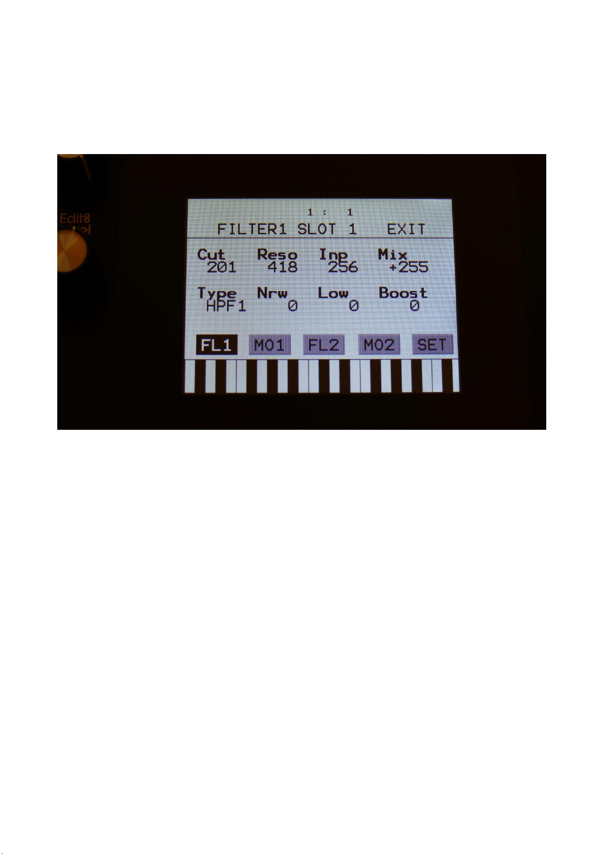
Touch the FL1 touch button, to enter the Filter 1 page.
Cut: 0 to 511. Sets the cutoff frequency of the filter.
Reso: 0 to 511. Sets the amount of resonance applied to the filter.
Inp: 0 to 511. Sets the audio signal input level to the filter. Different characteristics can be
obtained by adjusting this.
Mix: -256 to +255. Sets the mix between the audio input signal and the filter output signal. At +0
the input signal is passed through. At positive values, the the filter output is added to the input
signal. At negative values, an inverted version of the filter output is added to the input signal. At
+255 and -256 only the output of the filter is heard.
Type: Sets the filter type. See the list of filter types.
Nrw: 0 to 511. Turning this up, will make the frequency response of the filter more and more
narrow.
74
Page 75

Low: 0 to 511. Sets the lowest frequency offset point of the filter. Turning this up, will in many
filter types, make the bass bottom more present or distorted.
Boost: 0 to 511. Gains the filter output level.
75
Page 76

Filter 1 Modulation
Touch the MO1 touch button, to enter the Filter 1 Modulation page.
The small VU-meters next to the parameters, shows the activity of the selected modulation
sources.
For each parameter, that can be modulated, it is possible to select a modulation source, and to
adjust the modulation amount. Only the positive modulation sources, can be selected by the Edit
Knobs. To make a modulation source negative, touch the modulation source parameter. For a
complete list of modulation sources, see the list in the start of this section.
Cut1, Cut2: Will modulate the filter cutoff frequency.
Reso: Will modulate the amount of resonance applied to the filter.
Mix: Will modulate the filter Mix.
76
Page 77

Filter 2
Touch the FL2 touch button, to enter the Filter 2 page.
Cut: 0 to 511. Sets the cutoff frequency of the filter.
Reso: 0 to 511. Sets the amount of resonance applied to the filter.
Inp: 0 to 511. Sets the audio signal input level to the filter. Different characteristics can be
obtained by adjusting this.
Mix: -256 to +255. Sets the mix between the audio input signal and the filter output signal. At +0
the input signal is passed through. At positive values, the the filter output is added to the input
signal. At negative values, an inverted version of the filter output is added to the input signal. At
+255 and -256 only the output of the filter is heard.
Type: Sets the filter type. See the list of filter types.
Nrw: 0 to 511. Turning this up, will make the frequency response of the filter more and more
narrow.
77
Page 78

Low: 0 to 511. Sets the lowest frequency offset point of the filter. Turning this up, will in many
filter types, make the bass bottom more present or distorted.
Boost: 0 to 511. Gains the filter output level.
78
Page 79

Filter 2 Modulation
Touch the MO2 touch button, to enter the Filter 2 Modulation page.
The small VU-meters next to the parameters, shows the activity of the selected modulation
sources.
For each parameter, that can be modulated, it is possible to select a modulation source, and to
adjust the modulation amount. Only the positive modulation sources, can be selected by the Edit
Knobs. To make a modulation source negative, touch the modulation source parameter. For a
complete list of modulation sources, see the list in the start of this section.
Cut1, Cut2: Will modulate the filter cutoff frequency.
Reso: Will modulate the amount of resonance applied to the filter.
Mix: Will modulate the filter Mix.
79
Page 80

Filters Setup
Touch the SET touch button, to enter the Filters Setup page.
Stereo: Off, On.
When off, the left and the right audio signals, coming from the oscillators (only really effective,
when stereo samplings are played back), are mixed to one mono signal, that goes through both
filters.
When on, filter 1 affects only the left channel of the audio signal, and filter 2 affects only the right.
Conn: Filters connection parallel (Par) or serial (Ser).
Link: Off, On. When on, any setting made on filter 1, is automatically performed on filter 2 too.
Can be useful for stereo performance.
80
Page 81

VCA
The VCA is the last stage of a synth part, before the audio is sent to the Audio Bus system. The
audio output from the digital filter, goes into the VCA.
The VCA’s can behave in 4 different modes. Linear, logarithmic, smooth linear and smooth
logarithmic. The smooth VCA modes behaves like the VCA’s found in most other synthesizers.
The audio output of the VCA can be level modulated and panned. Pan can also be modulated. The
output of the VCA can be sent to 2 audio busses at the same time. When set up like this, the pan
control/modulation, is panning the audio signal between the 2 audio busses. For a stereo panned
output, one of these busses must be set to the right audio output, and the other to the left.
It is also possible to send one bus to output effect 1, and the other to output effect 2. Then the
pan control/modulation will mix between the 2 effects. Of course, filters and insert effects can
also be placed on these busses, for more sonic possibilities.
An ADSR envelope are attached to the VCA. The VCA envelopes can either be in linear or
logarithmic mode. A Drone parameter are available, for opening the VCA without the envelope
needing to be trigged. VCA output level are modulated by the attached ADSR envelope. Attack and
release can be modulated by any modulation source.
81
Page 82

VCA Parameters
From the synth parts main page, touch VCA to enter the VCA pages.
Touch the VCA touch button, to enter the VCA parameters page.
The VU-meter at the right of the screen, shows the VCA output activity.
A: 0 to 511. VCA envelope attack time. The time it will take the VCA envelope to rise from zero to
its maximum value, when a note event is received and held down.
D: 0 to 511. VCA envelope decay time. When the VCA envelope has reached its maximum value, in
the time set by the attack parameter, it will decay, until it reaches the sustain level, and stay there,
as long as the note that trigged it is held.
S: 0 to 511. VCA envelope sustain level. Explained under the ”D” parameter.
R: 0 to 511. VCA envelope release time. The time it will take the VCA envelope to decay from the
value it is at, when a note off event are received, to zero.
82
Page 83

Bus: 1/2 , 3/4 , 5/6 , 7/8 , 1, 2, 3, 4, 5, 6, 7, 8. Selects to which Audio Bus(ses) the VCA should
output its audio to. When 2 busses are selected, the pan parameter and modulation, pans the
audio signal between the 2 busses.
Mode: Selects if the VCA behaviour should be linear (Lin), logarithmic (Log), smooth linear (LinSM)
or smooth logarithmic (LogSM). The logarithmic curve gives the sound a softer and less “clicky”
attack. The smooth modes produces no clicking at all.
Drone: 0 to 511. VCA envelope drone offset level. When this is turned up, the VCA envelope will
never reach an output value, lower than what this is adjusted to –It will release to this adjusted
value, instead of zero. Use this to keep the output of a synth part open for drone sounds.
Level: The VCA output level.
83
Page 84

VCA Modulation
Touch the MOD touch button, to enter the VCA modulation page.
The VU-meter at the right of the screen, shows the VCA output activity. The small VU-meters next
to the parameters, shows the activity of the selected modulation sources.
For each parameter, that can be modulated, it is possible to select a modulation source, and to
adjust the modulation amount. Only the positive modulation sources, can be selected by the Edit
Knobs. To make a modulation source negative, touch the modulation source parameter. For a
complete list of modulation sources, see the list in the start of this section.
A: Modulates the VCA Envelope attack time.
R: Modulates the VCA Envelope release time.
Level: Modulates the output level of the VCA.
Pan: Modulates the output panning of the VCA. When source is set to manual (“Man”), the
amount parameter manually adjusts the output panning.
84
Page 85

Envelope 1 and 2
Each Synth part of Tiny LD has 2 modulation envelopes. One ADSR type, and one decay only
envelope. Envelope 1, the ADSR envelope can have linear or logarithmic charateristics and it also
has an offset control.
Envelope 2, the decay envelope, is always linear.
85
Page 86

Envelope 1 and 2 Parameters
From the synth parts main page, touch ENV to enter the envelope pages.
Touch the ENV touch button, to enter the envelope parameters page.
The VU-meter at the right of the screen, shows the Envelope output.
A: 0 to 511. Envelope 1 attack time. The time it will take the envelope to rise from zero to its
maximum value, when a note event is received and held down.
D: 0 to 511. Envelope 1 decay time. When the envelope has reached its maximum value, in the
time set by the attack parameter, it will decay, until it reaches the sustain level, and stay there, as
long as the note that trigged it is held.
S: 0 to 511. Envelope 1 sustain level. Explained under the ”Dec” parameter.
R: 0 to 511. Envelope 1 release time. The time it will take the envelope to decay from the value it
is at, when a note off event are received, to zero.
Offs: Offset:
86
Page 87

-Off: The envelope will work around the zero point, and apply both negative and positive
modulation to the parameters affected by it.
-On: Positive only, offset added. The envelope will only work above the zero point, and will only
add to the values of the parameters affected by it.
Mode: Selects if the envelope curve should be linear (Lin), or logarithmic (Log). The logarithmic
curve gives the envelope a softer and less “clicky” attack.
D2: 0 to 511. Envelope 2 decay time. The time it will take the decay envelope to decay, after it has
been trigged.
87
Page 88

Envelope Modulation
Touch the MOD touch button, to enter the envelope modulation page.
The VU-meter at the right of the screen, shows the Envelope output. The small VU-meters next to
the parameters, shows the activity of the selected modulation sources.
For each parameter, that can be modulated, it is possible to select a modulation source, and to
adjust the modulation amount. Only the positive modulation sources, can be selected by the Edit
Knobs. To make a modulation source negative, touch the modulation source parameter. For a
complete list of modulation sources, see the list in the start of this section.
A: Modulates the Envelope 1 attack time.
D: Modulates the Envelope 1 decay time.
R: Modulates the Envelope 1 release time.
AM: Modulates the Envelope 1 output amount.
88
Page 89

LFO1 to 16
Tiny LD has 16 LFO’s, that are global, so each LFO can modulate any of the 16 Synth parts.
The LFO's has continuosly variable waveform and rate parameters. Both of these parameters can
be modulated. The output level of the LFO’s can also be modulated, and they can be key-synced.
One LFO are shown at a time on the LFO pages. LFO 1 to 16 are selected in the same way as synth
parts are, by pushing and holding the Steps/Part button, while pressing a step button. The LFO’s
are though selected separately from the parts. So LFO 5 can for instance be selected, while part 3
is selected.
89
Page 90

LFO parameters
From the synth part main page, touch the LFO block, to enter the LFO pages.
Touch the LFO touch button, to select this page.
At the right of this page, the current LFO waveform is shown, together with a small VU-meter,
showing the LFO output activity.
Rate: 0 to 511. LFO rate. Sets the speed of the LFO.
Wave: 0 to 511. LFO output waveform. Morphs between triangle, sawtooth, square, pulse and FM
waveforms. The FM waveforms are high frequency waves, that can be used for FM synthesis.
AM: Selects the modulation source, that will control the LFO output level. If “Off” is selected, no
output level control will be applied to the LFO. Any modulation source can be selected. Please see
list of modulation sources in the beginning of this section.
KeyS: Off, 1 to 16: LFO key sync.
Off: The LFO is free running.
1 to 16: Every time this Synth part is trigged, the LFO will reset to its initial value, and start over.
90
Page 91

Touch the MOD touch button, to select this page.
The VU-meter at the right of the screen, shows the LFO activity. The small VU-meters next to the
parameters, shows the activity of the selected modulation sources.
For each parameter, that can be modulated, it is possible to select a modulation source, and to
adjust the modulation amount. Only the positive modulation sources, can be selected by the Edit
Knobs. To make a modulation source negative, touch the modulation source parameter. For a
complete list of modulation sources, see the list in the start of this section.
The upper row of parameters selects the modulation sources, the lower row of parameters
(Labelled Amt) adjusts the modulation amount in the range 0 to 511.
The parameters on this page:
Rate: Modulates the LFO rate.
Wave: Modulates the LFO waveshape.
91
Page 92

Audio Inputs Setup
Each audio input on Tiny LD, can input to an audio bus. The setup of this, is done in this section.
From the synth parts main page, touch INP, to enter this page:
InpL, InpR: Off, 1 to 8. Sets the audio bus, that the corresponding audio input is sent to. When set
to off, the audio input is not sent to any bus.
92
Page 93

Analog FilterBoard (Optional)
If you ordered the “Analog Filterboard Connector” together with your Tiny LD, it will have room
for an analog filterboard. There are several analog filterboards to choose from, each with their
own “flavour”.
The analog filterboard can be placed on audio busses, to process the signals applied to these. They
will be placed before any insert effects on the same bus.
Modulation can be applied from any of the 16 synth parts.
Most of the parameters of the analog filter can be adjusted and modulated. The analog options of
Tiny LD also adds a G-Ray digital/analog feedback circuit to the filters. This creates a kind of
intermodulated feedback signal, and makes it possible to create sounds similar to FM plus new
and never heard before sounds.
To make sure that the parameters on the pages fits the installed filterboard, some filters needs to
be configured. This is done in the “MOR” section. If you ordered your Tiny LD together with the
analog filterboard, this has already been configured.
93
Page 94

From the synth parts main page, touch MOR on the top navigation bar. On the MOR page, touch
VCF TYPES, to enter this page:
Here you can, by adjusting edit knob 1, set up which filterboard are installed in the filterboard slot.
VCF1, 2, 3, 4 and 9 should be set to 1-Most Filters.
The MiniProhet filter should be set to 5-MiniProphet.
The SP Filter should be set to 6-SP Filter.
The Tubaz filter should be set to 7-Tubaz.
The Dual Band SSI filter should be set to 8-Dual Band SSI.
94
Page 95

Analog Filterboard Parameters
From the synth parts main page, touch the VCFs block, to enter the analog filter pages.
The VCF page, when VCF1, 2, 3, 4 or 9 are installed:
Touch the VCF touch button, to enter this page.
The VU-meter at the right of the screen, shows the filter output activity.
Cut: 0 to 511. Adjust the filter cutoff frequency.
Peaks: 0 to 511.
On single filters: If the filter has more than one filter block, this will adjust the cutoff frequency
offset of block 2 or block 3+4. If the filter has only one block (see the documentation for the filter),
this will have no function.
On dual filters: This will adjust the cutoff frequency offset of filter 2.
On tripple filters: This will adjust the cutoff frequency offset of the middle filter, which is usually a
bandpass filter.
On VCF9: This will adjust the Distortion Drive.
Reso: Adjusts the resonance of the filter. On dual and tripple filters, this adjusts the resonance on
all filters.
95
Page 96

Feed:
On single filters: This will adjust the feedback of the filter. – means negative feedback, + means
positive feedback, 0 means no feedback.
On dual filters: This will adjust the negative feedback of the filter. -256 means no feedback, +255
means full negative feedback.
On tripple filters: This will adjust the cutoff frequency of the third filter (HPF).
LPF, BPF, HPF:
On single filters: Switches on and off the low pass, band pass and high pass outputs on the filter.
At least one of these must be on, to get a sound out of the filter.
On dual filters: Switches on and off the low pass, band pass and high pass outputs of filter 2. Filter
1, which is a band pass filter on VCF2, is always on.
On trippple filters: Switches on and off the low pass, band pass and high pass outputs of filter 1, 2
and 3. The trippple filter has 3 separate filters, to generate each of these outputs, and their cutoff
frequency can be separately adjusted.
Out1/2:
On single and dual filters: Mix between the clean filter sound, and the filter sound with added
analog distortion.
On tripple filters: Mix between LPF + BPF + HPF and 3x BPF.
96
Page 97

The VCF page, with VCF 5, MiniProphet filter installed:
Touch the VCF touch button, to enter this page.
The VU-meter at the right of the screen, shows the filter output activity.
Cut: 0 to 511. Adjust the filter cutoff frequency.
Reso: 0 to 511. Adjusts the resonance of the filter.
LPF1: Switches filter output 1 between 24dB and 12dB steepness.
18dB: Switches the 18dB lowpass block on filter output 2 on or off. The phase of this is inverted
compared to the phase of the 12 and 24 dB outputs on output 1, so when mixing with these,
different filter modes can be obtained.
6dB: Switches the 6dB lowpass block on filter output 2 on or off. The phase of this is inverted
compared to the phase of the 12 and 24 dB outputs on output 1, so when mixing with these,
different filter modes can be obtained.
Out1/2: Mixes between the filter outputs 1 (12dB/24dB) and 2 (Inversed 6dB/18dB).
97
Page 98

The VCF page, with VCF 6, SP filter installed:
Touch the VCF touch button, to enter this page.
The VU-meter at the right of the screen, shows the filter output activity.
Cut: 0 to 511. Adjust the filter cutoff frequency.
Reso: 0 to 511. Adjusts the resonance of the filter.
Rate: Sample Rate. 0 to 60 KHz.
Bits: Bit depth. 12 or 6 bit.
Out1/2: Adds an analog Fuzz effect, when turned up.
98
Page 99

The VCF page, with VCF 7, Tubaz filter installed:
Touch the VCF touch button, to enter this page.
The VU-meter at the right of the screen, shows the filter output activity.
Cut: 0 to 511. Adjust the filter cutoff frequency.
Reso: 0 to 511. Adjusts the resonance of the filter.
Cut3/Feed: -256 to +255. Negative feedback.
Out1: BPF or LPF select.
Out2: Always HPF.
Out1/2: Mix between filter output 1 (BPF/LPF) and filter output 2 (HPF).
99
Page 100

The VCF page, with VCF8, Dual Band SSI filter installed:
Touch the VCF touch button, to enter this page.
The VU-meter at the right of the screen, shows the filter output activity.
HpCut: HPF/LPF 1 and 2 filter cutoff frequency. Space between the 2 filters can be adjusted with
Space.
LpCut: LPF 1 and 2 filter cutoff frequency. Space between the 2 filters can be adjusted with Space.
Reso: Filter resonance of all 4 filters.
Space: Space between the cutoff frequencies of the two filter chains.
HPF2: HPF2 filter mode HPF or LPF.
HPF1: HPF1 filter mode HPF or LPF.
Conn: Connection of the 2 filter chains. Ser (serial) or Par (parallel).
Out1/2: Mix between filter output 1 (HPF/LPF + LPF chain 1) and filter output 2 (HPF/LPF + LPF
chain 2).
100
 Loading...