

Page 1
Gotharman’s aNamoNo
Xmini
Modular Synthesizer
User Manual V 2.27
Page 2

Contents Of This Manual
Introduction 5
Very special thanks to 6
Getting Started 7
Structure 13
User Interface 15
Preset Select Screen 19
Selecting a preset 20
The Triggers 22
The Synth 23
Available Modules in the Synth Section 24
List of Synth Modulation Sources 25
List of Synth Audio Bus Sources 28
Accessing the Synth Pages 29
Editing the parameters of the Modules 32
Connecting Modules 33
The Synth Modules 36
Zones 37
Trigger Setup 38
Oscillator 1 to 4 42
Sampler 1 to 4 48
Noise Generator 53
VCF –analog filter 55
Ring VCA 1 to 4 67
VCA 1 to 4 69
Envelope 1 to 4 75
EFX 1-4 79
Effects Select Page 80
List Of Effects 81
Effects Parameters 83
Filter 83
Chorus 85
Distortion 88
Bit Crush 91
Pitch Shifter 93
Resonator 96
Stretcher 98
FM 100
Delays 103
Page 3

Granulator 106
Variator 109
Reverb 111
Glitch Shifters 114
Pitch Shaper 117
Pitch Shaper 2 120
Wave Shaper 123
EFX 1 to 4 Inputs Select 125
LFO1-4 125
Random Generator 1 to 4 131
The Sequencer 133
Sequencer playback start/stop 134
Sequencer Main 138
Realtime Record 139
Clear Seq 140
Note Track Sequencer 141
Note Steps Edit 141
Gate Time Steps Edit 144
Delay Time Steps Edit 146
Note Track Mod Page 148
Clear Note Track 150
Mute/Unmute Tracks 151
Controller Tracks 153
Controller Steps Edit 153
Slide Steps Edit 156
Controller Track CC page 159
Clear Controller Track 160
Synth and Sequencer Morphing 161
More… preset parameters 162
Common Settings 165
Morph Setup 167
Touch Keyboard Settings 169
CV Inputs 172
CV Outputs 174
Initialize Preset 177
Morph Layer Copy 178
VCF Type 181
Checking FLASH memory 182
Delete Sample Bank A 183
Delete Sample Bank B 184
Delete All Presets and Songs 185
C.P. 186
PRS 187
Page 4

Save Preset 188
Song Mode 194
Accessing Song Mode 195
Song Edit Page 199
Song Select Page 202
Song Realtime Recording 205
Save Song 209
Initialize Song 215
Sample Record And Edit 217
Recording a Sample 220
Edit A Sampling 227
Adjusting start and end points 228
Sample Chops 229
Generating Sample Chop Points 232
Deleting a Sample 234
USB 235
Importing Files 237
Importing Multiple Files 239
Reload Multiple Files 240
Open a Directory 242
Make a new Directory 243
Delete file from USB drive 244
Export samples, presets and songs 245
Update Firmware 247
Analog Filter Install/Replace 254
MIDI Specs 264
Page 5

Introduction
A modular synthesizer in a compact box!
Thank you very much for purchasing/consider to purchase a Gotharman’s Anamono Xmini
Modular Synthesizer.
The Xmini has a number of built-in "modules", like oscillators, samplers, an analog filter, LFO's
and so on. Every module has a number of modulation input connectors, and most modules also has
a number of audio input connectors. For the modulation input connectors any modulation output
from any other module can be connected. For the audio input connectors, any audio output from any
other module can be connected. The analog filter also appears as a module.
It also has a new very sensitive capacitive touch screen, that is used for navigation, sequencer input,
and as a touch keyboard.
To make everything work as fast and effective as possible, Xmini is not programmed behind any
"OS". Everything is performed directly by the processor, and everything is programmed in
assembly language, which is up to 30 times more effective than the C++ language, that most people
program in, and it is programmed specificly for the aNamoNo Xmini hardware.
1024 preset slots and 1024 song slots are available, all user programmable.
Page 6

Very special thanks to:
Julien Huet
Florian Bielmann
Nick Nimick
Weinglas
Christopher Rayce
Richie Prado
For supporting this project from the beginning. I really appreciate your trust. Without you,
Anamono Xmini might not have been…
Gotharman July 2017
Page 7
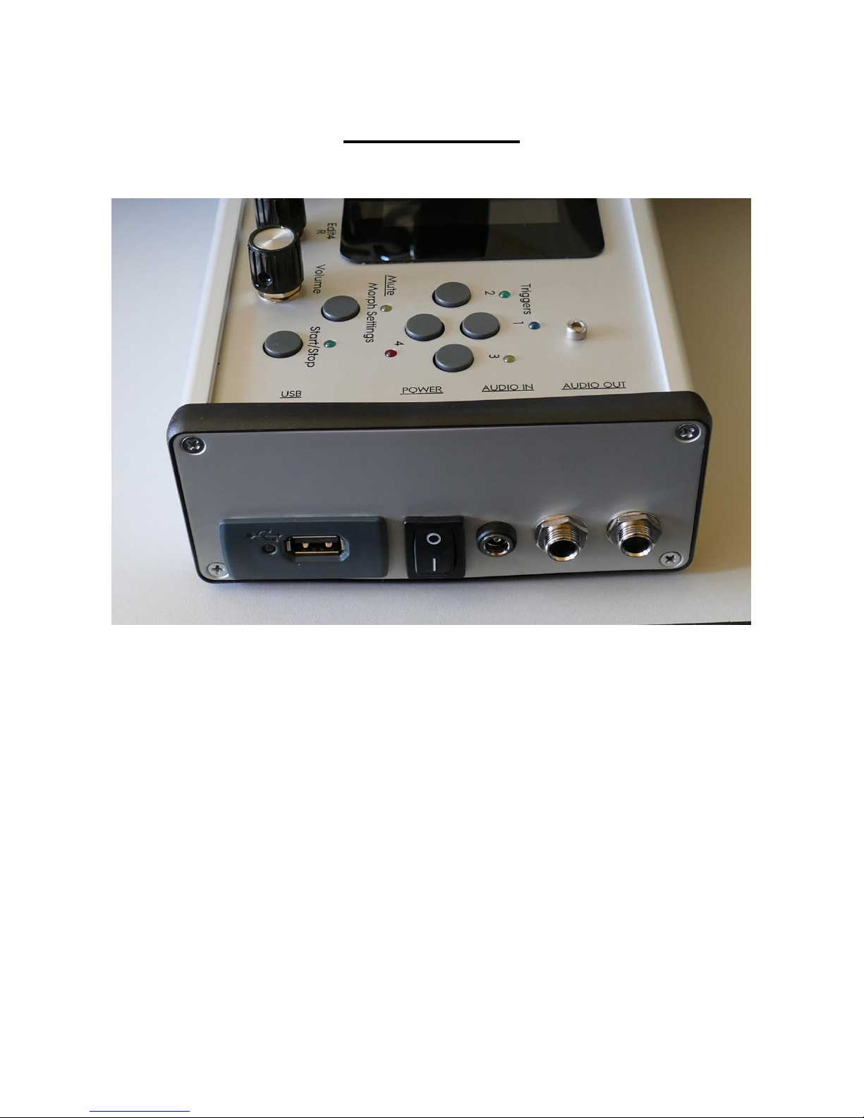
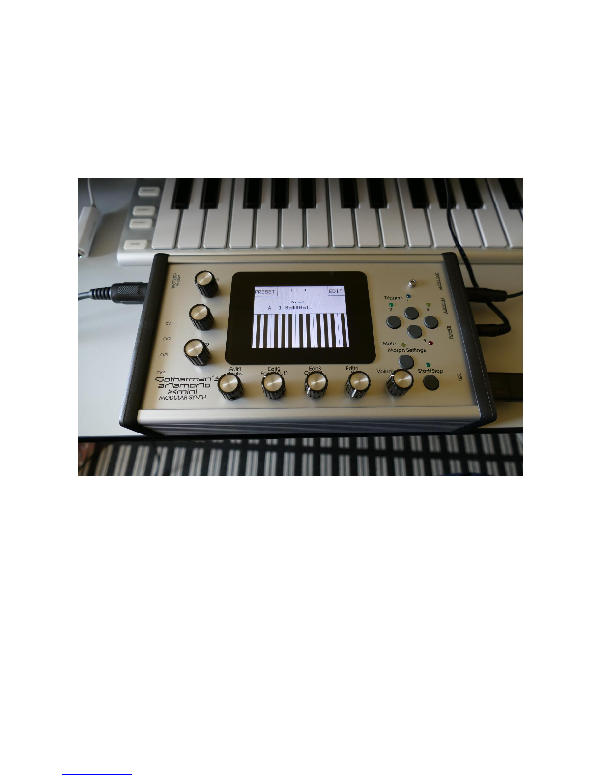
Getting Started
Connecting:
On the right end panel of your Xmini, you will find the power switch, connection for power supply,
audio input and output, and USB.
You would probably want to connect the audio output to a mixer or an amplifier, or anything else
that ends out in a speaker/a set of speakers. Since Xmini doesn’t have built in speakers, it just needs
to be connected to something, that can transfer its amazing sound to you.
Connect any line audio source to the audio input, for sampling and/or processing through Xmini’s
analog filter and effects. The audio input always goes through the analog filter, so the input signal
are available on the analog filter output. If you have no analog filter installed in your Xmini, the
audio input will not be available.
To the USB connector, a USB drive can be connected.
This should be:
-Maximum 32 GB
-FAT formatted
Page 8

With a USB drive connected, you can:
-Import, export and back up samples as .wav files
-Import, export and back up Xmini presets and songs
-Update Xmini
To import a .wav file from another device, it must be:
-Mono or stereo
-44.1 KHz sample rate – Xmini will import other sample rates, but they will play back in a wrong
speed
-16 bit native PCM
-It is not compatible with broadcast wav files. To convert broadcast wav files, found in many
downloadable sample sets, to standard wavfiles, please use a program like NCH Wavepad or NCH
Switch.
Page 9
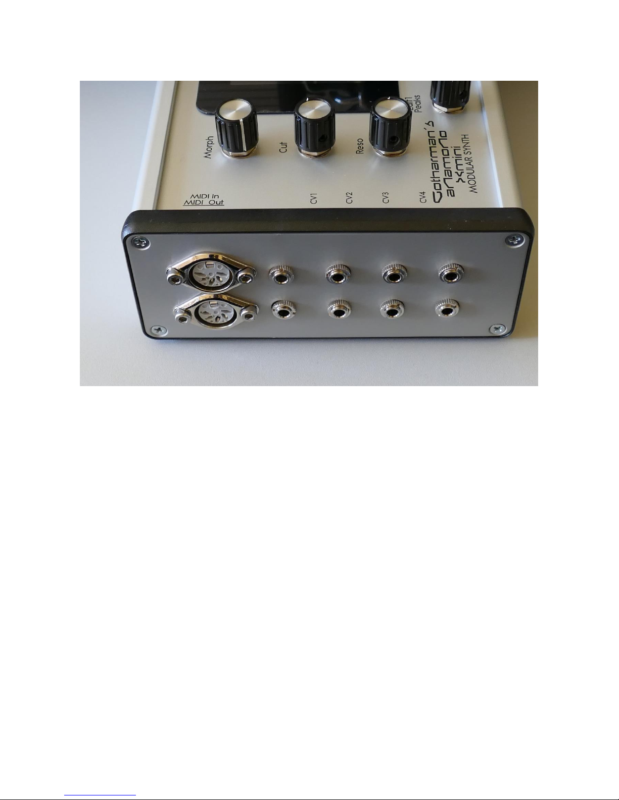
On the left end panel of your Xmini, you will find the MIDI in and out connectors. The optional CV
inputs and outputs are also found here, if installed. Please notice, that the upper row of CV
connectors are the outputs, and the lower row are the inputs. The upper MIDI connector are the
input, and the lower are the output.
If the Xmini touch screen keyboard seems too limited, you might want to connect a MIDI keyboard
to MIDI in, in order to take full advantage of Xmini’s fully chromatically playable sounds. It is also
possible to connect anything that transmits a MIDI clock, if you would like the sequencer of Xmini
to sync to your setup.
On MIDI out, MIDI clock, MIDI CC’s form the Xmini edit knobs, and notes and CC’s from its
sequencer are transmitted. Connect any MIDI gear to this, that you would like to control from
Xmini.
Connect any CV voltage source to the 4 CV inputs. Each input can be set up to match the voltage
range of any CV source, up to +/- 15 volts. The CV inputs can be used as modulation for any Xmini
module and as trigger sources.
Via the CV outputs it is possible to control analog gear. Each CV output, outputs both an adjustable
static voltage, plus an Xmini modulation source, so it is possible to both adjust t.ex. the cutoff
frequency of a connected analog filter, and to add modulation to this. It can even output audio
through these outputs.
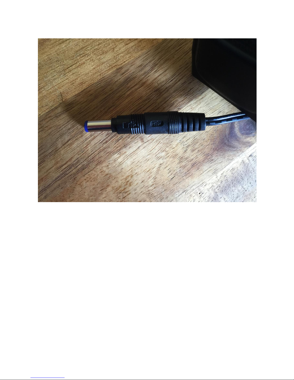
Page 10

Connect the supplied power adaptor to the Power input, and to a 100V to 240V power source.
It’s a 9V, minimum 1.5A type with a 2.1 mm DC plug, with positive middle.
Some Xmini’s might have been shipped out with a power adaptor, that has multiple tips. If you
have received one of these, you should use the tip with the blue ring, and make sure that the 2 parts
are alligned to the text “Tip”:
Please look at the picture, on the next page….
Page 11
Page 12

Turn it on
Push the “I” on the power switch. Your Xmini should now turn on.
Page 13
Page 14

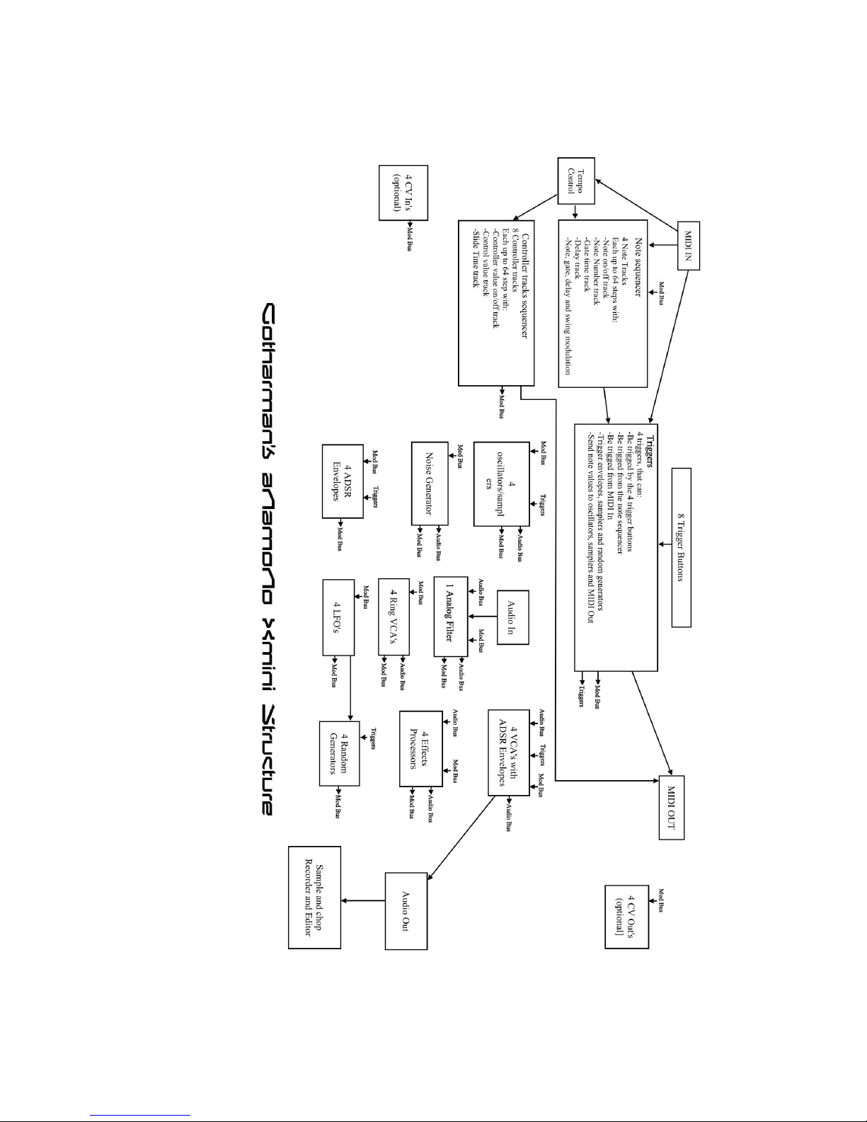
Xmini has a modular structure. It has a number of internal “modules”, like oscillators, samplers,
analog filter and effects processors, that all has a number of inputs and outputs.
These inputs and outputs are divided into 3 categories:
-Triggers
-Modulation (Mod Bus on the structure drawing)
-Audio (Audio Bus on the structure drawing)
Any trigger output can be connected to any trigger input, any modulation output can be connected
to any modulation input and any audio output can be connected to any audio input.
Many of the audio outputs of the Xmini modules are also connected to the modulation bus, to make
audio frequency modulation (often referred to as “FM”) possible of any parameter.
The oscillators, samplers and the noise generator, all outputs their audio signal to both the
modulation bus and the audio bus. They also outputs a low frequency version of themselves to the
modulation bus, so these audio generators can be used as both audio generators/audio frequency
modulators and as low frequency modulators at the same time.
Additionally the 4 Ring VCA’s can be used as “bus converters”. Since they take their inputs from
the modulation bus, and outputs to both the modulation and the audio bus at the same time, it is
possible to route any modulation signal to the audio bus through these. You could, for instance, add
pitch shifting to an LFO…
In order to trigger anything on Xmini, either via MIDI, the internal sequencer or the 4 trigger
buttons, it has to be done through the “Triggers” section, so this must be set up properly for each
preset, depending on what you want.
It is though also possible to get sound out of Xmini, without any triggering if needed, simply by
turning up the “Drone” parameter in any of the 4 VCA’s, and connect some sound generators to
this.
Only the 4 VCA’s can be connected to the audio output, so all sounds must output through a VCA.
The 4 track Note Sequencer always has track 1 connected to Trigger 1, track 2 connected to trigger
2 and so on…
Each trigger is then set up, to what each sequencer track should control, and it is possible to control
both internal modules an external MIDI devices.
The 8 tracks of the Controller sequencer all appear as modulation sources, and for each track, it is
possible to set a CC number and a MIDI transmit channel, to make it control external MIDI devices.
Page 15
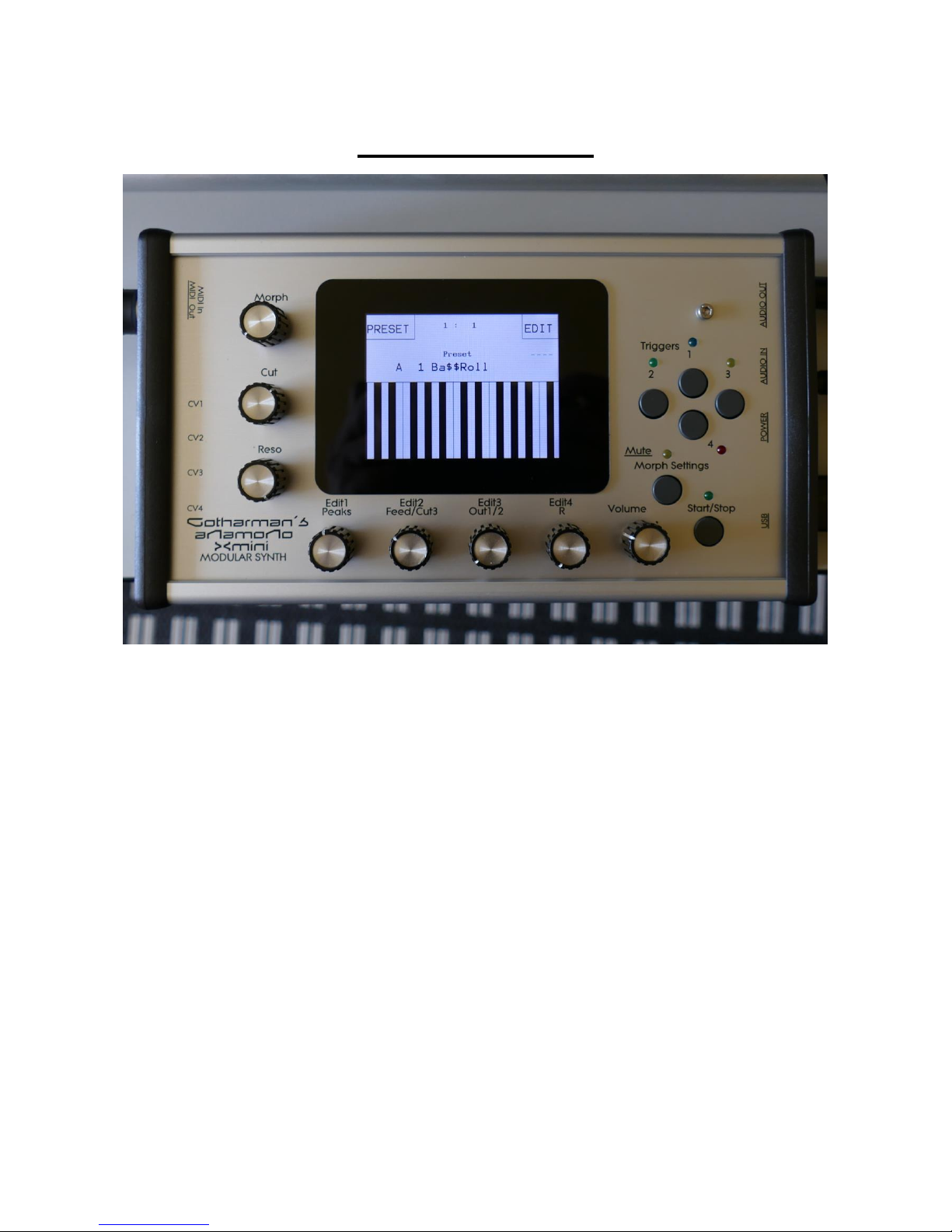
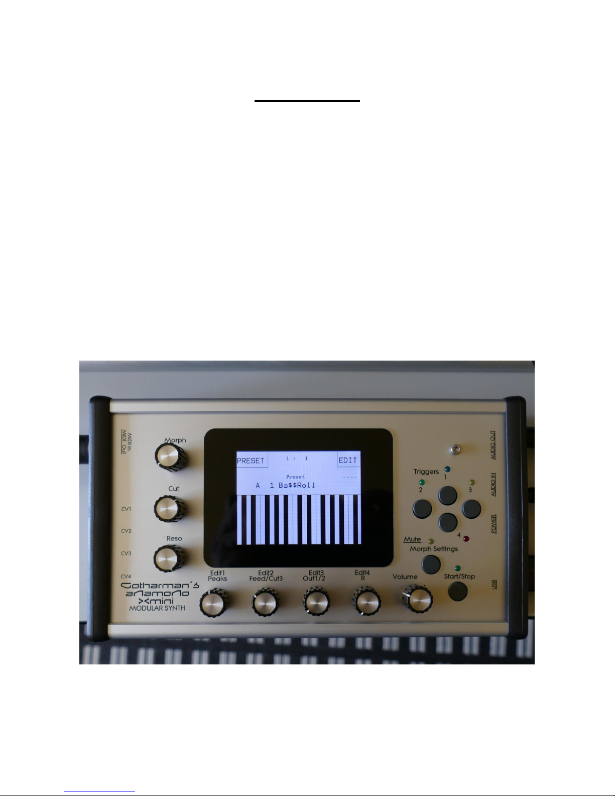
The User Interface
Xmini has a highly sensitive capacitive touch display, 4 trigger buttons, a Morph Settings button
and a Sequencer Start/Stop button. It has 4 Edit/Quick Edit Knobs for controlling and editing
parameters and sending MIDI CC’s, 2 additional Quick Edit Knobs, a Morph knob, and a volume
knob.
Each sampler and envelope module can be set up to be trigged from a trigger button. The trigger
buttons can also send note values to oscillators and samplers. It is also possible to just make a
trigger button send a note value to another trigger button. The setup of these will be described later
in this manual (in the synth section). When a trigger is trigged, the LED near it will light up.
The Start/Stop button will start and stop Sequencer playback. When the sequencer is playing back,
the green LED above the Start/Stop button will light.
The Morph Settings button, will toggle the parameters on any Synth and Sequencer page, between
2 layers of parameters, A and B. The Morph knob will morph between the two layers of either
Synth parameters or Sequencer parameters, as set up on the Morph Edit page, described later in this
manual.
The Volume knob always adjusts the audio output volume.
Page 16

The Edit 1-4 Knobs below the display, adjusts the parameters on each page. On the Preset Select
screen, they acts as modulation sources, that controls any parameters that has knob1 to 4 set as
modulator, and transmits MIDI CC’s. Any Edit Knob, that has not been assigned as a modulator to
any parameter, acts as a Quick Edit Knob.
The Quick Edit Knobs controls:
-Edit Knob 1: Analog filter peaks.
-Edit Knob 2: Analog filter feed/cut3.
-Edit Knob 3: Analog filter Out 1/2.
-Edit Knob 4: VCA envelope 1 release time.
The 2 additional Quick Edit Knobs always controls the Cut and Reso parameters of the analog
filter, and transmits MIDI CC’s.
Page 17
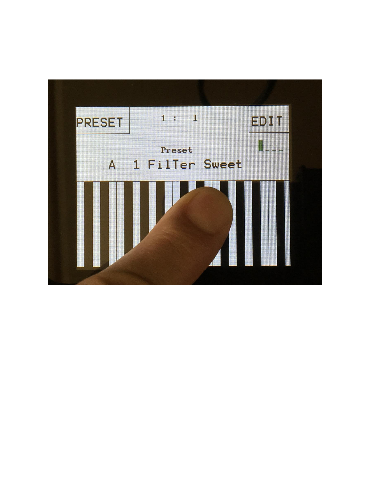
The Touch Screen Keyboard
The Xmini display is touch sensitive. The touch interface is used for navigating through the edit and
settings pages, and in the bottom of most pages, a fully playable touch keyboard is present.
On the Preset and Song Select pages, it is, besides from playing notes on the touch keyboard, also
possible to apply modulation to the sound, by placing your finger on different positions between the
top and the bottom of the keyboard. This is referred to as Keyboard Y modulation. On any other
pages, the keyboard only plays notes.
The touch keyboard work in the same way as a connected MIDI keyboard. Each of Xmini’s 4
triggers can be set up to work inside a specific note range. The keyboard will, when a note is
played, activate the trigger that has been set up to be triggerered by this note.
Page 18
The number of octaves for the touch keyboard is settable for each preset, to any number between 1
and 8.
It is also possible to set, which note the first key should play.
Page 19
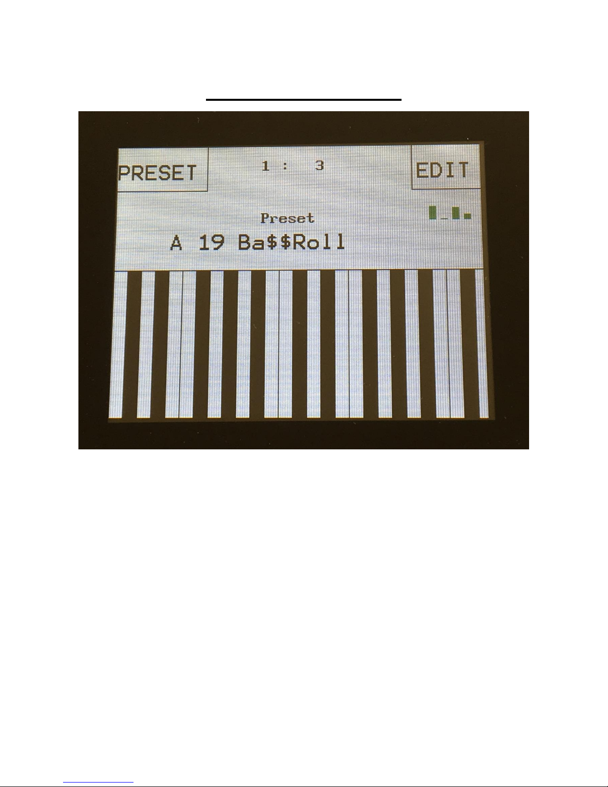
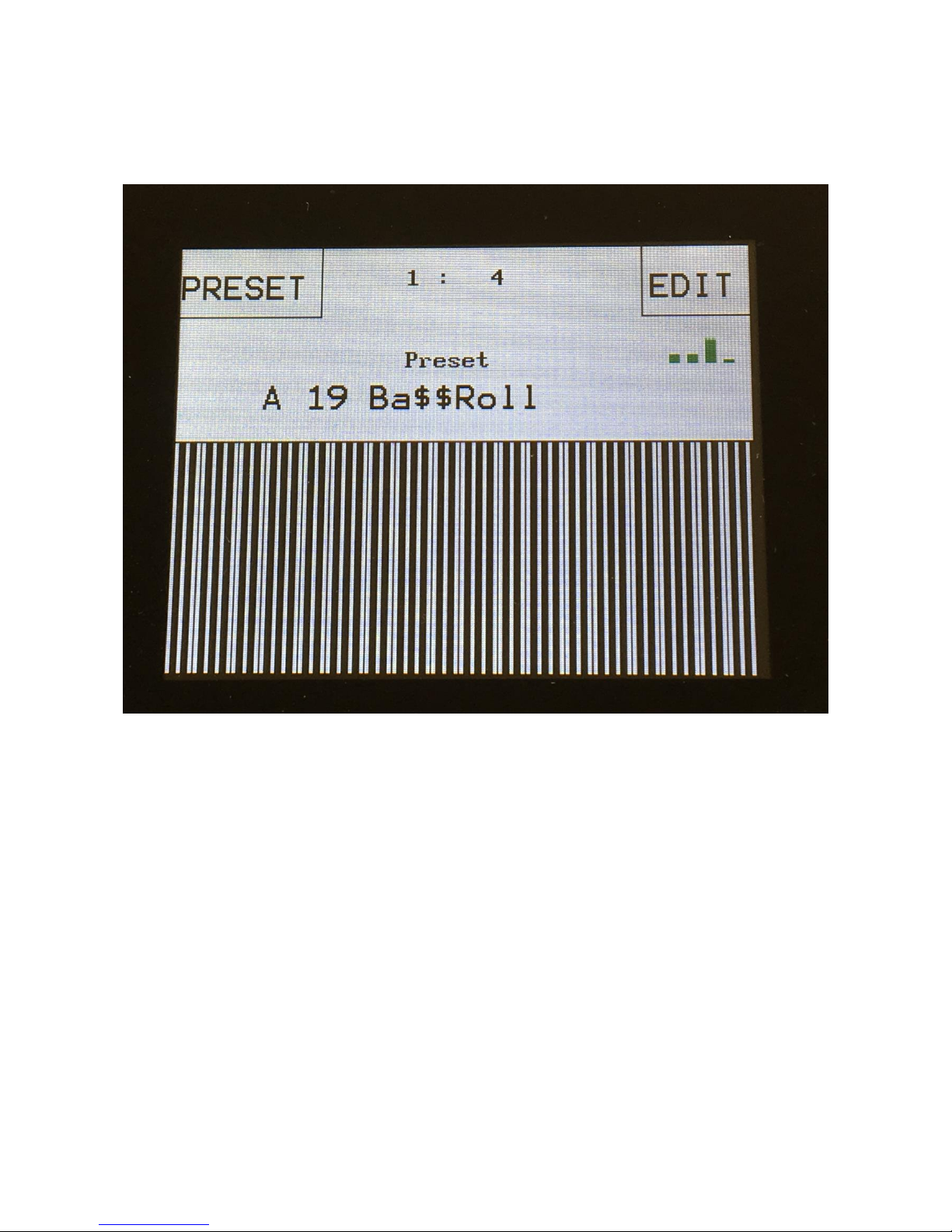
The Preset Select Screen
This is the first screen you will see, right after Xmini’s start-up screen, unless you left your Xmini
in Song mode, the last time it was turned off. Here you can change preset and jump to Xmini’s edit
and settings pages.
On the top of this screen, the Sequencer bar/beat, that is currently being played back, is shown.
Below this, it says “Preset”, if Xmini is currently in preset mode, or “Song” if Anamono X currently
are in song mode.
Below this, the number and name of the currently selected preset/song is shown.
Below the preset name/number, you will find the touch screen keyboard.
On the left side of the screen, 4 small VU-meters are shown. These show the output activity of VCA
1 to 4.
Touch the “EDIT” field in the upper right corner of the screen, to enter the edit and setup pages.
Touch the “PRESET” field, to select a memorized preset.
Page 20
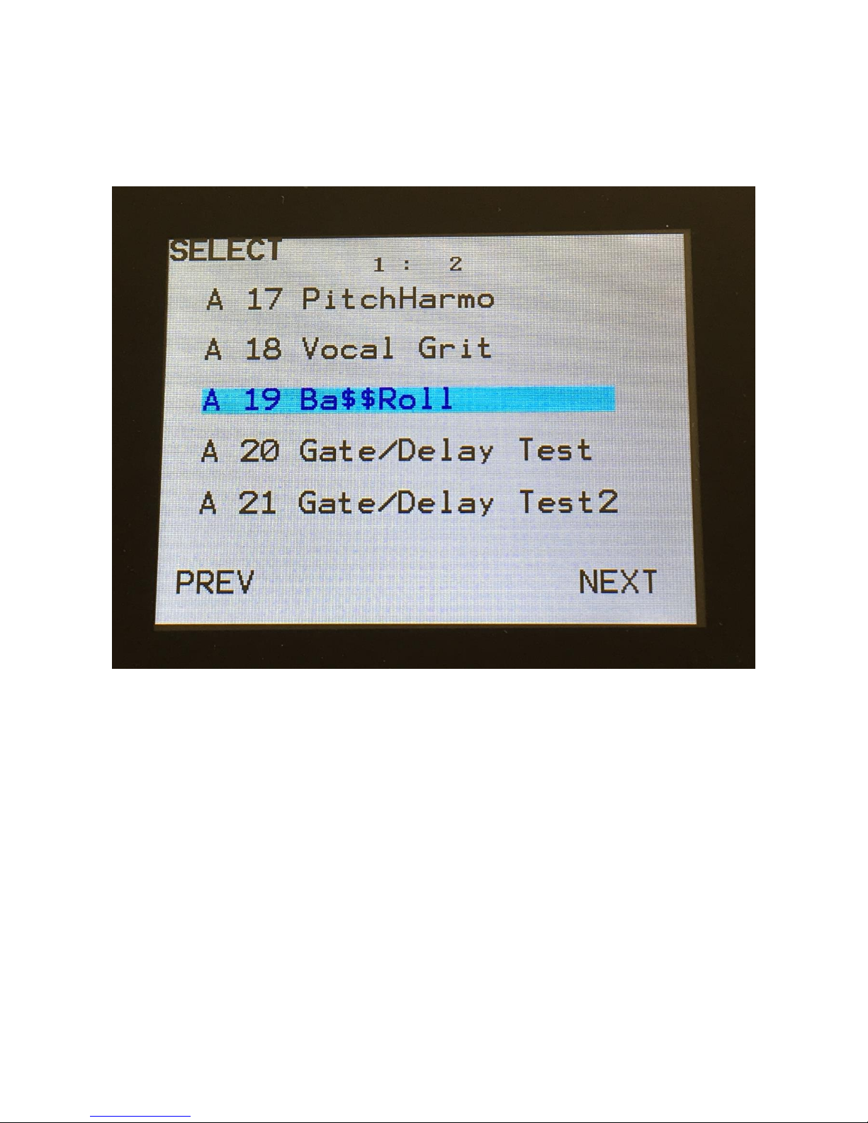
Selecting a preset:
Touch the “PRESET” field. A list of 5 presets near the currently selected preset, will now appear:
Touch “PREV” or “NEXT” to view the previous or next 5 presets, and finally touch the preset name
of the preset you would like to select. 1024 presets can be selected, from A01 to P64.
Xmini will now jump back to the main Preset Select screen, and show the name of the newly
selected preset.
If the sequencer is playing back, the Start/Stop LED will now start to flash, and the text “NEXT:”
will show right above the new presets name, awaiting track 1 to reach its end. As soon as this
happens, Xmini will switch to the newly selected preset, the Start/Stop LED will stop flashing, and
“NEXT:” will dissapear.
If the sequencer is not playing back, Xmini will immediately switch to the new preset, when you
touch the preset name.
When Xmini is turned off, it will remember which preset was selected, and start up with this, when
turned on again. It will also remember if it was in preset or song mode, and start up in the same
mode, and if it was in song mode, it will also remember which song was selected.
Page 21

On the Preset Select page, the 7 Edit/Quick Edit Knobs will transmit MIDI CC’s to Xmini’s MIDI
out, on the Xmini MIDI channel.
Edit Knob 1 to 4 will transmit MIDI CC 1 to 4.
The Morph knob will transmit and receive MIDI CC 11.
The Cut knob will transmit and receive MIDI CC 10.
The Reso knob will transmit and receive MIDI CC 9.
Page 22
The Triggers
Every time you want to trigger something in Xmini, either through the 4 trigger buttons, the touch
screen keyboard or a connected MIDI keyboard or pad controller, it has to go through the trigger
system, so you might want to set this up. The Xmini trigger system is much simpler than the
Anamono X trigger system. Each oscillator/sampler and envelope can be trigged by one trigger.
After a preset init, everything is automatically set up to be trigged by trigger 1.
On any page, it is possible to trigger 4 internal events, like envelopes and samplings, and/or external
MIDI devices, and to make oscillators play a specific note, using the trigger buttons.
To play the triggers, simply hit the corresponsive buttons. A trigger buttons LED will light up,
every time it is trigged.
It is possible to record the triggers actions into a sequencer track, and it is possible to control the
triggers from MIDI gear connected to the Xmini MIDI input.
The triggers are set up in the “Synth” section, explained from the next page in this manual.
Remember to save all edits you do in the Triggers section. Else they will be lost when you
change preset, or turn Xmini off. See how to in the ”Save Preset” section.
Page 23

The Synth
This is where all the exciting stuff happens
Here Xmini has a number of “modules” like oscillators, samplers, analog filters, modulators and
even effects processors, that can be connected to each other in absolutely any way you like. Just like
you can do with cables on a modular system.
The big ups are though: Xmini can memorize anything and you won’t get a huge bunch of cables on
your desk!
Remember to save all edits you do in the synth section. Else they will be lost when you change
preset, or turn Xmini off. See how to in the ”Save Preset” section.
Page 24

Available Modules in the Synth Section:
-4 Oscillators/Samplers
-1 Noise Generator
-Up to 1 Analog Filter
-4 Ring VCA’s
-4 VCA’s
-8 Envelopes
-4 LFO’s
-4 Random Generators
-4 Effects Processors
Please find each module described later in this section.
Page 25

List of Synth Modulation Sources:
Osc1: The audio range output of Oscillator/Sampler 1
Osc1-: The inverted audio range output of Oscillator/Sampler 1
Osc2: The audio range output of Oscillator/Sampler 2
Osc2-: The inverted audio range output of Oscillator/Sampler 2
Osc3: The audio range output of Oscillator/Sampler 3
Osc3-: The inverted audio range output of Oscillator/Sampler 3
Osc4: The audio range output of Oscillator/Sampler 4
Osc4-: The inverted audio range output of Oscillator/Sampler 4
Nois: The audio range output of the Noise Generator
Nois-: The inverted audio range output of the Noise Generator
SLN: Slow Noise. The low frequency output of the Noise Generator
SLN-: Inverted Slow Noise. The Inverted low frequency output of the Noise Generator
Slo1: Slow Oscillator 1. The low frequency output of Oscillator 1
Slo1-: Inverted Slow Oscillator 1. The Inverted low frequency output of Oscillator 1
Slo2: Slow Oscillator 2. The low frequency output of Oscillator 2
Slo2-: Inverted Slow Oscillator 2. The Inverted low frequency output of Oscillator 2
Slo3: Slow Oscillator 3. The low frequency output of Oscillator 3
Slo3-: Inverted Slow Oscillator 3. The Inverted low frequency output of Oscillator 3
Slo4: Slow Oscillator 4. The low frequency output of Oscillator 4
Slo4-: Inverted Slow Oscillator 4. The Inverted low frequency output of Oscillator 4
Aen1: The output of VCA Envelope 1
Aen1-: The output of VCA Envelope 1 Inverted
Aen2: The output of VCA Envelope 2
Aen2-: The output of VCA Envelope 2 Inverted
Aen3: The output of VCA Envelope 3
Aen3-: The output of VCA Envelope 3 Inverted
Aen4: The output of VCA Envelope 4
Aen4-: The output of VCA Envelope 5 Inverted
Vcf: The audio range output of the Analog Filter
Vcf-: The audio range output of the Analog Filter Inverted
Efx1: The audio range output of Effects Processor 1
Efx1-: The audio range output of Effects Processor 1 Inverted
Efx2: The audio range output of Effects Processor 2
Efx2-: The audio range output of Effects Processor 2 Inverted
Efx3: The audio range output of Effects Processor 3
Efx3-: The audio range output of Effects Processor 3 Inverted
Efx4: The audio range output of Effects Processor 4
Efx4-: The audio range output of Effects Processor 4 Inverted
Seq1: The output of Sequencer Controller Track 1
Seq1-: The output of Sequencer Controller Track 1 Inverted
Seq2: The output of Sequencer Controller Track 2
Seq2-: The output of Sequencer Controller Track 2 Inverted
Seq3: The output of Sequencer Controller Track 3
Seq3-: The output of Sequencer Controller Track 3 Inverted
Seq4: The output of Sequencer Controller Track 4
Seq4-: The output of Sequencer Controller Track 4 Inverted
Page 26

Seq5: The output of Sequencer Controller Track 5
Seq5-: The output of Sequencer Controller Track 5 Inverted
Seq6: The output of Sequencer Controller Track 6
Seq6-: The output of Sequencer Controller Track 6 Inverted
Seq7: The output of Sequencer Controller Track 7
Seq7-: The output of Sequencer Controller Track 7 Inverted
Seq8: The output of Sequencer Controller Track 8
Seq8-: The output of Sequencer Controller Track 8 Inverted
Ring1: The output of Ring VCA 1
Ring1-: The output of Ring VCA 1 Inverted
Ring2: The output of Ring VCA 2
Ring2-: The output of Ring VCA 2 Inverted
Ring3: The output of Ring VCA 3
Ring3-: The output of Ring VCA 3 Inverted
Ring4: The output of Ring VCA 4
Ring4-: The output of Ring VCA 4 Inverted
Env1: The output of Envelope 1
Env1-: The output of Envelope 1 Inverted
Env2: The output of Envelope 2
Env2-: The output of Envelope 2 Inverted
Env3: The output of Envelope 3
Env3-: The output of Envelope 3 Inverted
Env4: The output of Envelope 4
Env4-: The output of Envelope 4 Inverted
LFO1: The output of LFO1
LFO1-: The output of LFO1 Inverted
LFO2: The output of LFO2
LFO2-: The output of LFO2 Inverted
LFO3: The output of LFO3
LFO3-: The output of LFO3 Inverted
LFO4: The output of LFO4
LFO4-: The output of LFO4 Inverted
Rnd1: The output of Random Generator 1
Rnd1-: The output of Random Generator 1 Inverted
Rnd2: The output of Random Generator 2
Rnd2-: The output of Random Generator 2 Inverted
Rnd3: The output of Random Generator 3
Rnd3-: The output of Random Generator 3 Inverted
Rnd4: The output of Random Generator 4
Rnd4-: The output of Random Generator 4 Inverted
CV1: The voltage apllied to CV Input 1
CV1-: The voltage apllied to CV Input 1 Inverted
CV2: The voltage apllied to CV Input 2
CV2-: The voltage apllied to CV Input 2 Inverted
CV3: The voltage apllied to CV Input 3
CV3-: The voltage apllied to CV Input 3 Inverted
CV4: The voltage apllied to CV Input 4
CV4-: The voltage apllied to CV Input 4 Inverted
Page 27

Kybd: The last note number value received on MIDI in, on the Anamono X MIDI channel
Kybd-: The last note number value received on MIDI in, on the Anamono X MIDI channel
Inverted
Velo: The last note velocity value received on MIDI in, on the Anamono X MIDI channel
Velo-: The last note velocity value received on MIDI in, on the Anamono X MIDI channel Inverted
Aft: The last mono aftertouch value received on MIDI in, on the Anamono X MIDI channel
Aft-: The last mono aftertouch value received on MIDI in, on the Anamono X MIDI channel
Inverted
Knb1: Edit knob 1 value and the last MIDI CC 1 value received on MIDI in, on the Anamono X
MIDI channel
Knb1-: Edit knob 1 value and the last MIDI CC 1 value received on MIDI in, on the Anamono X
MIDI channel Inverted
Knb2: Edit knob 2 value and the last MIDI CC 2 value received on MIDI in, on the Anamono X
MIDI channel
Knb2-: Edit knob 2 value and the last MIDI CC 2 value received on MIDI in, on the Anamono X
MIDI channel Inverted
Knb3: Edit knob 3 value and the last MIDI CC 3 value received on MIDI in, on the Anamono X
MIDI channel
Knb3-: Edit knob 3 value and the last MIDI CC 3 value received on MIDI in, on the Anamono X
MIDI channel Inverted
Knb4: Edit knob 4 value and the last MIDI CC 4 value received on MIDI in, on the Anamono X
MIDI channel
Knb4-: Edit knob 4 value and the last MIDI CC 4 value received on MIDI in, on the Anamono X
MIDI channel Inverted
TouY: Touch screen keyboard Y-axis position
TouY-: Touch screen keyboard Y-axis position Inverted
Page 28

List of Synth Audio Bus Sources:
Osc1: Oscillator/Sampler 1
Osc2: Oscillator/Sampler 2
Osc3: Oscillator/Sampler 3
Osc4: Oscillator/Sampler 4
Noise: Noise Generator
Ring1: Ring VCA 1
Ring2: Ring VCA 2
VCF: Analog Filter Slot
VCA1: VCA1
VCA2: VCA2
VCA3: VCA3
VCA4: VCA4
EFX1: Effects Processor 1
EFX2: Effects Processor 2
EFX3: Effects Processor 3
EFX4: Effects Processor 4
Ring3: Ring VCA 3
Ring4: Ring VCA 4
RvF1: Reverb 1 feedback loop
RvF2: Reverb 2 feedback loop
Page 29

Accessing The Synth Pages
From the Preset/Song Select screen, Touch the “EDIT” field.
Page 30
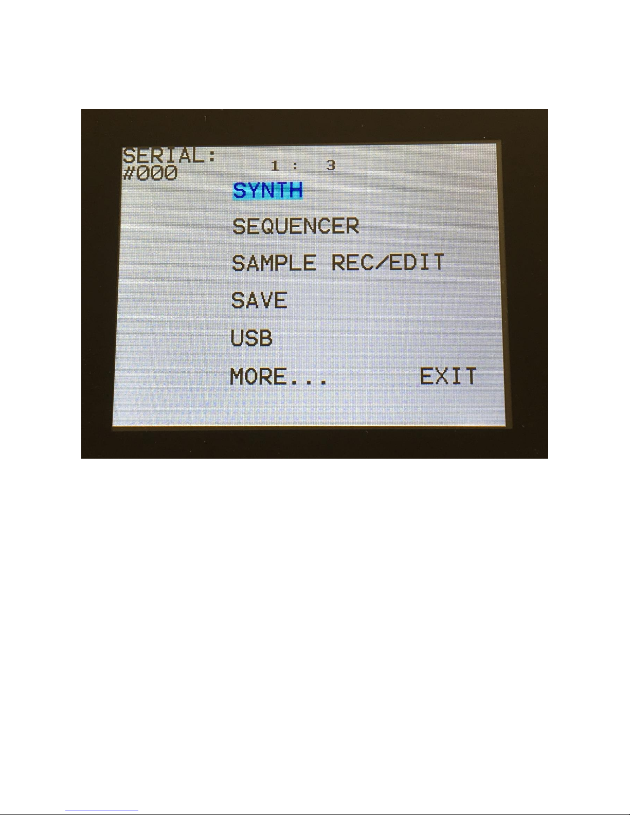
Now Xmini will show a list of the available edit groups:
In the upper left corner of this page, the serial number of your Xmini will show.
To enter the Synth edit pages, touch “SYNTH”.
Page 31

A list of the available Synth modules will now show:
To enter any of the Synth modules, simply touch the text showing the name of the module you
would like to enter.
To exit to the edit groups page, touch “EXIT”.
Page 32

Editing The Parameters Of The Modules
Each module page has up to 8 parameters, that can be edited. The parameters are shown on the
display as 8 parameter names, each with an alphanumeric value below them, that shows the current
value of the parameter.
By touching any of the 2 rows of parameters, you can select 4 parameters for editing at a time. The
selected row of parameters will have their value written inside a blue square.
When turning any of the 4 Edit Knobs, the corresponding selected parameter will be adjusted, and
you will hear a change in the sound, if the module is connected.
Right below the parameters, you will find the sub page select buttons (named “P_1”, “Mod” and
“Sel” on the shown page). By touching these, you can select different sub pages of the module, with
additional parameters.
In the upper right corner of each module, you will find “EXIT”. Touch this to exit to the synth
module overview page.
Page 33

Connecting Modules
On Xmini you do not need minijack cables or a computer to connect its modules, unless you are
connecting external analog devices via the CV inputs and outputs, of course. You just need to select
a module, touch the screen and turn a knob, and the module is connected! I will now explain how:
Nearly all modules has a ”mod” sub page button, and all modules that has audio inputs has an “Inp”
sub page button:
Page 34

When touching the “Mod” button, Xmini jumps to the Modulation page of the module:
On this page, you can, by turning Edit Knob 1 to 4, select the sources, that should be connected to
the modulation inputs of the module. The parameter names shows what parameter is being
modulated by the selected source.
By touching the lower row of parameters, to select these, you can adjust the modulation amount,
again by turning Edit Knob 1 to 4.
Page 35

When touching the “Inp” button, Xmini jumps to the inputs page of the module:
On this page, you can, by turning Edit Knob 1 to 4, select the sources, that should be connected to
the audio inputs of the module. Each module that has audio inputs, usually has 4 of these.
By touching the lower row of parameters, to select these, you can adjust the input level of each
source, again by turning Edit Knob 1 to 4.
Page 36

The Synth Modules
In this section all the modules of the Synth (synthesizer) section are explained. The modules of the
sequencer is not explained here, but in the Sequencer section later in this manual.
Page 37

ZONES
Here you can set up key zones for each of the 4 triggers. These zones are effective only when Xmini
is controlled from an external MIDI device or from the touch screen keyboard. It is also possible to
transpose the incoming notes individually for each trigger key zone.
When using the internal sequencer, note track 1 will always drive Trigger 1 in the full note range,
note track 2 will always drive Trigger 2 in the full note range and so on…
LO1, LO2, LO3, LO4: Sets the lowest note of trigger 1 to 4 MIDI note range. The note range of
trigger 1, will be from trigger 1 LO to trigger 2 LO. The note range of trigger 2, will be from trigger
2 LO to trigger 3 LO… and so on. The note range of trigger 4 will be from LO4 to G9.
Tps1, Tps2, Tps3, Tps4: Transposes the incoming notes up to 64 notes up or down, for each
trigger key zone.
Page 38

TRIG
The Trigger setup pages.
On these 4 pages, it is possible to set up what note each trigger button should send, if one trigger
button should trigger another, which trigger should trigger the oscillators and envelopes, and if the
triggers should transmit notes on MIDI out.
The first sub page looks like this:
Note1, Note2, Note3, Note4: Sets the note number that each trigger button should send to the
internal oscillators, when pushed. This setting only affects when the trigger buttons theselves are
pushed, not when a trigger is controlled via MIDI or the sequencer.
Tr1To, Tr2To, Tr3To, Tr4To: Off, 1 to 4. A trigger can send its note number to another trigger,
and trig this. This is done, by setting this parameter to any other value than Off. This can be useful,
if you for instance have trigger 1 set up over the whole key range, and you just want to trigger other
notes with the same modules as used by trigger 1.
Page 39

Sub page 2:
Osc1, Osc2, Osc3, Osc4: 1 to 4. Selects what trigger that should trigger each of the 4 samplers, and
send note numbers to the oscillators/samplers.
Page 40

Sub page 3:
VCA1, VCA 2, VCA 3, VCA 4, ENV1, ENV 2, ENV 3, ENV 4: 1 to 4. Selects what trigger that
should trigger each of the 4 VCA envelopes and the 4 modulation envelopes.
Page 41

Sub page 4:
On this page it is possible to select a MIDI note number and a MIDI channel, that will be
transmitted via MIDI out, when a trigger button is pushed. When a trigger button is set up to
transmit a MIDI note, the sequencer track attached to that trigger, will also transmit MIDI notes on
the same MIDI channel.
Midi1, Midi2, Midi3, Midi4: Off, C-1 to G9. The MIDI note number, that will be transmitted,
when pushing trigger button 1 to 4. When this is set to any other position than Off, the sequencer
note track attached to the trigger, will also transmit its notes via MIDI. The notes transmitted from
the sequencer are the notes programmed on the sequencer track, not the note number set here.
Chan1, Chan2, Chan3, Chan4: 1 to 16. The MIDI channel that trigger button 1 to 4/ sequencer
note track 1 to 4 will transmit on.
Page 42

OSC (Oscillator/Sampler) 1 to 4
For each of the 4 oscillators, it is possible to select if it should act as an oscillator or a sampler.
In oscillator mode it generates a waveform that is morphable between sine, triangle, saw, pulse and
feedback waves. Pulse width are adjustable for all waveform types. Each oscillator also has a
suboscillator attached to them, that outputs a squarewave, one octave below the original pitch. The
oscillators outputs both an audio range signal and a low frequency version of this at the same time,
so the oscillators can function as both audio range sound/modulation sources and low frequency
modulation sources, at the same time. Pitch, PW, wave and suboscillator level can be modulated.
The oscillators can act as both audio and modulation sources. The pitch range of the oscillators are
chromatically over the entire 10 octave MIDI keyboard range.
In sampler mode it plays back any of the 256 storable samplings, that can either be recorded on
Xmini itself in the Sample Rec section, or be imported in the USB section. Each sampler has 4
sample slots, that each can contain one sampling, and a set of parameters for Pitch, start, length and
chop point. Pitch, chop, start point and length can be adjusted and modulated. Samples are
chromatically tuned, and has a pitch range of 4 octaves above and 5 octaves below the original
sample pitch. Loop mode can be set to Off, On or Free. In Free mode the sampling is constantly
playing back, and is never re-trigged. So if you set it up to go through a VCA, and set this up to be
Page 43

opened by a trigger, a different portion of the sampling will be played back every time the VCA is
opened. Samplings can act as both audio and modulation sources. Like the oscillators, the samples
also outputs a low frequency version of itself, so samples can be used as low frequency modulation
too.
Sampler modules can load and playback Little deFormer samples and use the chop points. It is also
possible to create chop points in the Xmini sample editor, and use these. Chops can be detected by
level peaks or by single wavecycles. Single wavecycle chops are an easy way to make loops.
Both oscillators and samplers has a portamento control.
Page 44

Oscillator 1 to 4 parameters
The oscillator pages, when an oscillator are in oscillator mode.
In the bottom right of the oscillator page, the current waveform is shown.
Tune: Adjust the basic pitch in semitones. Range: -64 to + 63.
Fine: Fine tuning of the pitch. Range: -256 to +255.
Wave: This parameter lets you morph between sine, triange, saw, pulse and feedback waves.
PW: Adjusts the pulse width of the waveform. Unlike many other oscillator designs, the pulse
width can be adjusted on all of Xmini’s waveforms, not just the pulse wave.
Sub: Sub Oscillator Level. When turned up, a square wave, one octave below the oscillator
frequency, is added to the oscillator signal. Range: 0 to 511.
Sync: Oscillator Sync. When this is in any other position than Off, the selected oscillator will sync
to one of the other oscillators. Range: Off, Osc1 toOsc 4.
Page 45

Porta: Portamento. The more this is turned up, the slower the oscillator pitch will slide from one
note to another. Range: 0 to 511.
Page 46

Oscillator 1 to 4 modulation
At any of the 4 Oscillator pages, touch the ”Mod” button, to enter the modulation page:
The small VU-meters next to the parameters, shows the activity of the selected modulation sources.
For each parameter, that can be modulated, it is possible to select a modulation source, and to adjust
the modulation amount. For a complete list of modulation sources, see the list in the start of this
section.
The upper row of parameters selects the modulation sources, The lower row of parameters
(Labelled Amt) adjusts the modulation amount in the range 0 to 511.
The parameters on this page:
Pitc: Modulates the oscillator pitch.
Wave: Modulates the wave select morphing.
PWM: Modulates the pulse width of the waveform
Page 47

Sub: Modulates the level of the sub-oscillator square wave.
Page 48

Sampler 1 to 4
The oscillator pages, when an oscillator are in sampler mode.
In the bottom of the sampler page, the selected sample waveform is shown in rough graphics. When
the sample, or part of it, is played back, the small black line below the waveform will show the
current playback point.
Tune: Adjust the basic pitch in semitones. Range: -64 to + 63.
Fine: Fine tuning of the pitch. Range: -256 to +255.
Start: The sample start point. Selects at what point the sample will start to play back, when it is
triggered. Range: 0 to 511, stretching over the whole sampling.
Length: Adjusts how much of the sampling should be played back. Range: 0 to 511, stretching over
the whole sampling.
Page 49

Loop: Sets the sampling loop mode.
Off: The sample will not loop, just play back one time from the adjusted, or chop selected, start to
end, and then stop.
On: The sample will play back from the adjusted start point, when triggered. When it reaches the
adjusted end point, it will loop back to the start point, and play back the sample over and over again.
Free: The sample will constantly be looping between the adjusted, or chop selected, start and
endpoints, regardless of if it is triggered or not.
Chop: If chop points has been generated for the selected sampling, a chop can be selected by
setting this parameter. Range: Off, 0 to 63.
xChp: Number of Chops to be played back in a row. Range: 1 to 64.
Porta: Portamento. The more this is turned up, the slower the sampler pitch will slide from one
note to another. Range: 0 to 511.
Page 50

Sampler 1 to 4 modulation
The small VU-meters next to the parameters, shows the activity of the selected modulation sources.
For each parameter, that can be modulated, it is possible to select a modulation source, and to adjust
the modulation amount. For a complete list of modulation sources, see the list in the start of this
section.
The upper row of parameters selects the modulation sources, The lower row of parameters
(Labelled Amt) adjusts the modulation amount in the range 0 to 511.
The parameters on this page:
Pitc: Modulates the sampler pitch.
Chop: Modulates the Chop number select.
Start: Modulates the sample start point.
Lengt: Modulates the sample length.
Page 51

Selecting oscillator/sample mode and samples for sampler 1 to 4
On any oscillator page, touch the Sel” button to enter this page:
Mode: Select whether the oscillator should be in oscillator or sampler mode.
In oscillator mode, the rest of the parameters on this page has no effect.
Page 52

In sampler mode:
Slot: Manual select of sample slot 1 to 4, for selecting a sampling for each slot, and for setting the
Tune, Start, Length and Chop parameters for each slot. If the Ssel parameter is set to “Man”
(manual slot select), the sample slot selected by this parameter, is played back by this oscillator.
Ssel: Sample Slot Select. Set this to “Man” (manual), to select the sample slot to play back
manually by the Slot parameter, or set it to any modulation source, to make a modulation source
select the sample slot for play back. For a complete list of modulation sources, see the list in the
start of this section.
Chan: If a stereo sampling has been selected, this parameter will select if the right or the left audio
channel should play back.
When the sample number and name is selected:
Edit Knob 1 will select the sample bank (A or B), Edit Knob 2 will select any of the 128 possible
samplings in the selected bank.
Page 53

Noise
On the noise generator, the parameters shape, pulse width and mix (between pulse and voltage
noise) can be adjusted and modulated. It outputs to both the audio and the modulation bus, and like
the oscillators and samplers, this also outputs a slow version of itself. The rate of the slow wave can
be adjusted.
In the bottom right of the noise generator page, the current waveform is shown.
Shp: Noise Shape. The Noise Generator can make a lot of different noise shapes. Range: 0 to 511.
Mix: Mix between squared noise (at setting 0) and voltage noise (at setting 511). Range: 0 to 511.
PW: Adjusts the pulse width of the squared noise. Range: 0 to 511.
SLN: Slow noise wave rate. Range: 0 to 511.
Page 54

Noise Generator Modulation
The small VU-meters next to the parameters, shows the activity of the selected modulation sources.
For each parameter, that can be modulated, it is possible to select a modulation source, and to adjust
the modulation amount. For a complete list of modulation sources, see the list in the start of this
section.
The upper row of parameters selects the modulation sources, The lower row of parameters
(Labelled Amt) adjusts the modulation amount in the range 0 to 511.
The parameters on this page:
Shp1 and Shp2: Modulates the noise shape.
Mix: Modulates the mix between squared and voltage noise.
Pwm: Modulates the pulse width of the squared noise.
Page 55

VCF –The analog filter in the filter slot
An analog filter can be installed in Xmini. This is located in a slot, that becomes visible, when
removing the left side panel. Xmini will also work, without an analog filter installed.
Different types of analog filters will be available, to mount in the slot. See “Replacing/Mounting the
analog filter” later in this manual, for details on this.
The analog filter is used just like any other Xmini module. It is possible to route any modulation
sources and audio signals to it, and it outputs on both the audio bus and the modulation bus. Cutoff
frequency, peaks (space between 2 cutoff frequencies), and resonance can be adjusted and
modulated. If the mounted filter has analog feedback, this can also be adjusted and modulated. LPF,
BPF and HPF filter modes can be switched on and off. Most filters has 2 audio outputs. The mix
between these can be adjusted and modulated. On the first filters, an analog overdrive circuit is
placed on output 2, so turning up the Out1/2 knob, will add analog overdrive to the filter sound. The
analog filters also has a G-Ray digital/analog feedback circuit attached to them. This creates a kind
of intermodulated feedback signal, and makes it possible to create sounds similar to FM plus new
and never heard before sounds.
On the More… page, it is possible to set which analog filter is installed, and make sure that the right
parameters will be shown.
Page 56

Analog Filter
Page 1 –Touch P_1 to enter this page
With VCF 1,2,3 or 4 installed:
The 2 VU-meters at the right of the screen, shows the filter outputs 1 and 2.
NOTE: An analog filter must be mounted in Xmini for the parameters in this section to have any
effect.
Cut: Adjust the filter cutoff frequency. Range: 0 to 511.
Peaks:
On single filters: If the filter has more than one filter block, this will adjust the cutoff frequency
offset of block 2 or block 3+4. If the filter has only one block (see the documentation for the filter),
this will have no function.
On dual filters: This will adjust the cutoff frequency offset of filter 2.
On tripple filters: This will adjust the cutoff frequency offset of the middle filter, which is usually a
bandpass filter.
Page 57

Reso: Adjusts the resonance of the filter. On dual and tripple filters, this adjusts the resonance on
all filters.
Cut3/Feed:
On single filters: This will adjust the feedback of the filter. – means negative feedback, + means
positive feedback, 0 means no feedback.
On dual filters: This will adjust the negative feedback of the filter. -256 means no feedback, +255
means full negative feedback.
On tripple filters: This will adjust the cutoff frequency of the third filter.
LPF, BPF, HPF:
On single filters: Switches on and off the low pass, band pass and high pass outputs on the filter. At
least one of these must be on, to get a sound out of the filter.
On dual filters: Switches on and off the low pass, band pass and high pass outputs of filter 2. Filter
1, which is a band pass filter on VCF2, is always on.
On tripple filters: Switches on and off the low pass, band pass and high pass outputs of filter 1, 2
and 3. The tripple filter has 3 separate filters, to generate each of these outputs, and their cutoff
frequency can be separately adjusted.
Out1/2:
On single and dual filters: Mix between the clean filter sound, and the filter sound with added
analog distortion.
On tripple filters: Mix between LPF + BPF + HPF and 3x BPF.
Page 58

With VCF 5, MiniProphet filter installed:
Cut: Adjust the filter cutoff frequency. Range: 0 to 511.
Reso: Adjusts the resonance of the filter.
LPF1: Switches filter output 1 between 24dB and 12dB steepness.
18dB: Switches the 18dB lowpass block on filter output 2 on or off. The phase of this is inverted
compared to the phase of the 12 and 24 dB outputs on output 1, so when mixing with these,
different filter modes can be obtained.
6dB: Switches the 6dB lowpass block on filter output 2 on or off. The phase of this is inverted
compared to the phase of the 12 and 24 dB outputs on output 1, so when mixing with these,
different filter modes can be obtained.
Out1/2: Mixes between the filter outputs 1 (12dB/24dB) and 2 (Inversed 6dB/18dB).
Page 59

With VCF 6, SP filter installed:
Cut: Adjust the filter cutoff frequency. Range: 0 to 511.
Reso: Adjusts the resonance of the filter.
Rate: Sample Rate. 0 to 60 KHz.
Bits: Bit depth. 12 or 6 bit.
Out1/2: Adds an analog Fuzz effect, when turned up.
Page 60

With VCF 7, Tubaz filter installed:
Cut: Adjust the filter cutoff frequency. Range: 0 to 511.
Reso: Adjusts the resonance of the filter.
Cut3/Feed: Negative feedback.
Out1: BPF or LPF select.
Out2: Always HPF.
Out1/2: Mix between filter output 1 (BPF/LPF) and filter output 2 (HPF).
Page 61

Analog Filter
Page 2 –Touch P_2 to enter this page
The 2 VU-meters at the right of the screen, shows the filter outputs 1 and 2.
NOTE: An analog filter must be mounted in Xmini for the parameters in this section to have any
effect.
G-Ray: Adjusts the amount of g-RAY intermodulation. 0: no g-RAY, 3: max g-RAY. Range: 0 to
3.
Mode: G-Ray mode.
-Norm: Normal 1:1 feedback.
-Neg: 1:1 feedback with the signal inverted (a 180 degree phase shift)
-Ultr: Boosted feedback.
-Uneg: Boosted feedback with the signal inverted (a 180 degree phase shift)
Feed: G-Ray feedback level. Range: 0 to 511.
Page 62

Input: Selects the input to the G-Ray feedback circuit. Can be either analog filter output 1 or 2, or
the mix adjusted with the Out1/2 parameter.
Peaks: Selects how the Peaks parameter should interact with the Cutoff frequency parameter:
-Add: The value of the Peaks parameter is added to the Cutoff value.
-Sub: The value of the Peaks parameter is subbed from the Cutoff value.
-Alig: The value of the Peaks parameter are alligned around the Cutoff value.
-Sepa: The value of the Peaks parameter are a totally separate value, and are not affected by the
Cutoff value.
Cut3: Selects the function of the Feed/Cut3 parameter:
-Feed: The value of the Feed/Cut3 parameter are a totally separate value, and are not affected by
the Cutoff value. This setting is the recommended one, when a single or a dual filter are installed,
and the Feed/Cut3 should work as Feed.
The next possible modes, are mostly usable, when a tripple analog filter are installed:
-Add: The value of the Feed/Cut3 parameter is added to the Cutoff value.
-Sub: The value of the Feed/Cut3 parameter is subbed from the Cutoff value.
-Alig: The value of the Feed/Cut3 parameter are alligned around the Cutoff value.
Out2: Selects whether output 2 of the analog filter should be normal (Nrm) or inverted (Inv).
Sometimes it can get some great effects, when inverting output 2 of the filter, and adjust the Out1/2
mix.
Page 63

Analog Filter Modulation
Page 1 –Touch Mod1 to enter this page
The 2 VU-meters at the right of the screen, shows the filter outputs 1 and 2. The small VU-meters
next to the parameters, shows the activity of the selected modulation sources.
For each parameter, that can be modulated, it is possible to select a modulation source, and to adjust
the modulation amount. For a complete list of modulation sources, see the list in the start of this
section.
The upper row of parameters selects the modulation sources, The lower row of parameters
(Labelled Amt) adjusts the modulation amount in the range 0 to 511.
The parameters on this page:
Cut1 and Cut2: Modulates the Cutoff Frequency.
Peak1 and Peak2: Modulates the Peaks parameter.
Page 64

Analog Filter Modulation
Page 2 –Touch Mod2 to enter this page
The 2 VU-meters at the right of the screen, shows the filter outputs 1 and 2. The small VU-meters
next to the parameters, shows the activity of the selected modulation sources.
For each parameter, that can be modulated, it is possible to select a modulation source, and to adjust
the modulation amount. For a complete list of modulation sources, see the list in the start of this
section.
The upper row of parameters selects the modulation sources, The lower row of parameters
(Labelled Amt) adjusts the modulation amount in the range 0 to 511.
The parameters on this page:
Reso: Modulates the Resonance parameter.
Feed: Modulates the analog filter feedback/Cutoff frequency 3.
Out: Modulates the Out1/2 parameter.
Page 65

Gfeed: Modulates the G-Ray feedback.
Page 66

Analog Filter Inputs Select
-Touch Inp to enter this page
The 2 VU-meters at the right of the screen, shows the filter outputs 1 and 2. The small VU-meters
next to the parameters, shows the activity of the selected audio sources.
Each analog filter has 4 audio inputs. For each of these, an audio source can be selected, and the
input level can be adjusted. For a complete list of audio bus sources, see the list in the start of this
section.
The upper row of parameters selects the audio input sources, the lower row of parameters
(Labelled Lvl1-4) adjusts the input levels in the range 0 to 511.
Page 67

Ring VCA 1 to 4
The 4 Ring VCA's has 3 functions. They can act as:
-Ring Modulator -Connect 2 audio sources, and it will output a ring modulated signal.
-Modulation/audio source VCA -Connect an audio or a modulation source to input 1, and a
modulation source to input 2, and the modulator on input 2 will adjust the level of the source on
input 1.
-Modulation to audio convertor -If you would like, for instance, to route and envelope, LFO or even
a sequencer track through effects or filters, you can do this through a Ring VCA.
Ring VCA's outputs to both the audio and the modulation bus.
Page 68

Ring VCA 1 to 4 parameters
The small VU-meters next to the parameters, shows the activity of the selected source.
Inp1, Inp2, Inp3, Inp4: Connects any modulation source to the input of the Ring VCA. This is the
input, that gets modulated. Since this outputs to both the modulation and the audio bus, it can be
used to get modulation signals to the audio bus, if you, for any reason, would like to do that.
Mod1, Mod2, Mod3, Mod4: Connects any modulation source to the modulation input of the ring
VCA. The first source that can be selected are special to this module: Max. This just adds a
maximum value to the modulation input. Select this, if you just want to convert from modulation to
audio.
Setup examples:
Ring Modulator: Connect audio range modulators (like oscillators or samples) to both inputs.
Modulation VCA: Connect the source that you would like to be level modulated to “Inp”, and
connect the desired level modulator to “Mod”.
Modulation to audio converter: Connect the modulation source, that you would like to convert, to
“Inp”. Select “Max” as “Mod”.
Page 69

VCA1 to 4
Audio signals can be mixed and routed to the audio output through the VCA’s. Output can also be
switched off, if you only want to use a VCA for internal mix. An ADSR envelope are attached to
each of the VCA's. The VCA envelopes can either be in linear or logarithmic mode. A Drone
parameter are available, for opening the VCA without the envelope needing to be trigged. VCA
output level are modulated by the attached ADSR envelope. Attack, decay and release can be
modulated by any modulation source. The VCA's only outputs to the audio bus. If you need VCA's
for modulation signals, you should use a Ring VCA.
In order to trigger any envelope, you will have to set up a trigger to do this. See the “Triggers”
section earlier in this manual, for information on how to do this.
The VCA’s outputs only to the audio bus.
Page 70

VCA 1 to 4 parameters
Touch P_1 to enter this page
The 2 VU-meters at the right of the screen, shows the VCA input and output.
A: VCA envelope attack time. The time it will take the amp envelope to rise from zero to its
maximum value, when a note event is received and held down. Range: 0 to 511.
D: VCA envelope decay time. When the amp envelope has reached its maximum value, in the time
set by the attack parameter, it will decay, until it reaches the sustain level, and stay there, as long as
the note that trigged it is held. Range: 0 to 511.
S: VCA envelope sustain level. Explained under the ”Dec” parameter. Range: 0 to 511.
R: VCA envelope release time. The time it will take the amp envelope to decay from the value it is
at, when a note off event are received, to zero. Range: 0 to 511.
Outp: Selects whether the VCA should output to the audio output (On) or not (Off).
Page 71

Mode: Selects if the VCA envelope curve should be linear (Lin), or logarithmic (Log). The
logarithmic curve gives the sound a softer and less “clicky” attack.
Drone: VCA envelope drone offset level. When this is turned up, the amp envelope will never
reach an output value, lower than what this is adjusted to –It will release to this adjusted value,
instead of zero. Use this to keep the output of the synth open for drone sounds, or for external input
sounds. Range: 0 to 511.
Level: The VCA output level.
Page 72

VCA 1 to 4 Modulation
Touch Mod to enter this page
The 2 VU-meters at the right of the screen, shows the VCA input and output. The small VU-meters
next to the parameters, shows the activity of the selected modulation sources.
For each parameter, that can be modulated, it is possible to select a modulation source, and to adjust
the modulation amount. For a complete list of modulation sources, see the list in the start of this
section.
The upper row of parameters selects the modulation sources, The lower row of parameters
(Labelled Amt) adjusts the modulation amount in the range 0 to 511.
The parameters on this page:
A: Modulates the VCA Envelope attack time.
D: Modulates the VCA Envelope decay time.
R: Modulates the VCA Envelope release time.
Page 73

Outp: Modulates the output level of the VCA.
Page 74

VCA 1 to 4 Inputs Select
Touch Inp to enter this page
The 2 VU-meters at the right of the screen, shows the VCA input and output. The small VU-meters
next to the parameters, shows the activity of the selected audio sources.
Each VCA has 4 audio inputs. For each of these, an audio source can be selected, and the input
level can be adjusted. For a complete list of audio bus sources, see the list in the start of this section.
The upper row of parameters selects the audio input sources, the lower row of parameters
(Labelled Lvl1-4) adjusts the input levels in the range 0 to 511.
Page 75

Env1 to 4
4 modulation envelopes, with linear/logarithmic charateristics and an offset control.
In order to trigger any envelope, you will have to set up a trigger to do this. See the “Triggers”
section earlier in this manual, for information on how to do this.
The envelopes outputs only to the modulation bus.
Page 76

Envelope 1 to 4 parameters
Touch P_1 to enter this page
The VU-meter at the right of the screen, shows the Envelope output.
A: Envelope attack time. The time it will take the envelope to rise from zero to its maximum value,
when a note event is received and held down. Range: 0 to 511.
D: Envelope decay time. When the envelope has reached its maximum value, in the time set by the
attack parameter, it will decay, until it reaches the sustain level, and stay there, as long as the note
that trigged it is held. Range: 0 to 511.
S: Envelope sustain level. Explained under the ”Dec” parameter. Range: 0 to 511.
R: Envelope release time. The time it will take the envelope to decay from the value it is at, when a
note off event are received, to zero. Range: 0 to 511.
Page 77

Offs: Offset:
-Off: The envelope will work around the zero point, and apply both negative and positive
modulation to the parameters affected by it.
-On: Positive only, offset added. The envelope will only work above the zero point, and will only
add to the values of the parameters affected by it.
Mode: Selects if the envelope curve should be linear (Lin), or logarithmic (Log). The logarithmic
curve gives the envelope a softer and less “clicky” attack.
Page 78

Envelope 1 to 4 Modulation
Touch Mod to enter this page
The VU-meter at the right of the screen, shows the Envelope output. The small VU-meters next to
the parameters, shows the activity of the selected modulation sources.
For each parameter, that can be modulated, it is possible to select a modulation source, and to adjust
the modulation amount. For a complete list of modulation sources, see the list in the start of this
section.
The upper row of parameters selects the modulation sources, the lower row of parameters
(Labelled Amt) adjusts the modulation amount in the range 0 to 511.
The parameters on this page:
A: Modulates the Envelope attack time.
D: Modulates the Envelope decay time.
R: Modulates the Envelope release time.
Page 79

EFX 1 to 4
Here you will find 4 effects processors.
All effects has a bypass/Freeze switch and a mix parameter. All effects outputs to both the audio
and the modulation bus, and many parameters can be modulated.
Page 80

The Effects select page
Touch Sel to enter this page
On this first effects page, you can select the effect type for the effects processor, by turning Edit
Knob 1.
The 2 VU-meters at the right of the screen, shows the Effect input and output.
Page 81

List of Effects
Filter – 16 filter types and 2 EQ types. Derived from Fuzion.
Chorus – Gotharman's special chorus with an added Deep parameter, that adds space to the chorus.
Distortion – 4 types: Valve, Sine, Fuzz, Xdis.
Bit Crush – Lowers the sample rate and the bit resolution of the sound, to obtain lo-fi effects.
Pitch Shifter – Shift the pitch of the sound up to 4 octaves up or down, without changing the time
resolution or “tempo” of the sound. Adjustable sense.
Resonator – Simulates the resonances that comes, if a sound goes through a small box. Anamono
X’s resonators are synthetic, with more focus on making sounds, than on simulating actual boxes.
Stretcher – Tries to time stretch the input signal, while at the same time keeping up with it.
Impossible? -Yes, indeed :-)
FM – Adds self-FM to the input signal in +/- 1 octave, +/- 2 octaves or +/- 4 octaves ranges.
Delay 1 – Only EFX 1 and 2. Delay with time and feedback controls, plus Gotharman's Deep,
Size, Beam and Xfade controls. Deep adds space to the delay, Size makes the playback range more
narrow than the input recording range, and beam beams the delay to previously unknown places.
The Xfade control on this delay, creates valleys between the delay taps. The more it is turned up,
the more time the valleys takes up.
Roto Delay – Only EFX 1 and 2. New Gotharman delay! This is a 2 tap delay, that is constantly
crossfading between the 2 taps. When the Xfade control is turned down, the crossfading is rough,
the more it is turned up, the more smooth the crossfading gets. Other controls are the same as the
first delay.
Bright Delay – Only EFX 1 and 2. First delay, but with a brighter sound, created by a resonator.
Bright Roto Delay – Only EFX 1 and 2. Roto delay, but with a brighter sound, created by a
resonator.
Granulator – Only EFX 1 and 2. Cuts the input signal up in grains, that can be re-arranged. The
anAmoNo X granulator can sync to the sequencer.
Variator – Only EFX 1 and 2. Creates new variations of the input signal. Both pitch and rhythmic
variations.
Reverb – Only EFX 1 and 2. Takes up 2 effect slots: 1+3 and/or 2+4.
Glitch Shifter – Imperfect pitch shifter.
Page 82

Glitch Shifter 2 – Imperfect pitch shifter with a slightly different sound than the first one.
Pitch Shaper – 1 input version of Gotharman's special Pitch Shaper, that forces an audio signal to
play back at a specific pitch, determined by an adjustable frequency.
Pitch Shaper 2 – 2 input version of Gotharman's special Pitch Shaper, that forces an audio signal to
play back at a specific pitch, determined by the frequency of another audio signal.
Wave Shaper - Re-shapes the input signal.
Page 83

Effects Parameters
Filter
The 2 VU-meters at the right of the screen, shows the Effect input and output.
Efx: Off, on, Freeze. When the effect is off, it is bypassed, and its input mixer can function as a
mixer. When the effect are in Freeze mode, the input signal is no longer sampled. The sound that
the effect holds, will just keep playing back on and on again. NOT ALL EFFECTS ARE
AFFECTED BY FREEZE!
Mix: The mix between the un-effected signal on the effect input, and the effected signal on the
effect output, that is sent to the audio bus.
Cut: Filter cutoff frequency.
Reso: Filter resonance setting.
Page 84

Type: Filter type. Possibilities are:
-LPF: Low pass filter
-BPF: Band pass filter
-BP8: Steep band pass filter
-HPF: High pass filter
-ADD: Reverse filter. Adds harmonics to the sound.
-BEF: Band eliminate filter
-BASS: A filter with most power in the bass area
-LOFI: Agressive low pass filter
-LPF2: Low pass filter 2, with a slightly different response than the first variant
-BPF2: Band pass filter 2, with a slightly different response than the first variant
-BP82: Steep band pass filter 2, with a slightly different response than the first variant
-HPF2: High pass filter 2, with a slightly different response than the first variant
-ADD2: Reverse filter 2, with a slightly different response than the first variant
-BEF2: Band eliminate filter 2, with a slightly different response than the first variant
-BAS2: Bass filter 2, with a slightly different response than the first variant
-LOFI2: Agressive low pass filter 2, with a slightly different response than the first variant
-Peq1: Parametric EQ
-Peq2: Steeper parametric EQ
Adj1, Adj2, Adj3: Changes the filter response. For the parametric EQ types, Adj3 acts as
cut/boost.
Page 85

Filter Modulation
The 2 VU-meters at the right of the screen, shows the Effect input and output. The small VUmeters next to the parameters, shows the activity of the selected modulation sources.
For each parameter, that can be modulated, it is possible to select a modulation source, and to adjust
the modulation amount. For a complete list of modulation sources, see the list in the start of this
section.
The upper row of parameters selects the modulation sources, the lower row of parameters
(Labelled Amt) adjusts the modulation amount in the range 0 to 511.
The parameters on this page:
Cut1 and Cut2: Modulates the filter cutoff frequency.
Reso: Modulates the filter resonance.
Adj3: Modulates the filter adjust 3 parameter.
Page 86

Chorus
The 2 VU-meters at the right of the screen, shows the Effect input and output.
Efx: Off, on, Freeze. When the effect is off, it is bypassed, and its input mixer can function as a
mixer. When the effect are in Freeze mode, the input signal is no longer sampled. The sound that
the effect holds, will just keep playing back on and on again. NOT ALL EFFECTS ARE
AFFECTED BY FREEZE!
Mix: The mix between the un-effected signal on the effect input, and the effected signal on the
effect output, that is sent to the audio bus.
Feed: Chorus feedback amount.
Time: Chorus Time. This should be modulated by an LFO, to get the traditional chorus effect.
Deep: Adjusts how deep the chorus box should be. A Gotharman special.
Page 87

Chorus Modulation
The 2 VU-meters at the right of the screen, shows the Effect input and output. The small VUmeters next to the parameters, shows the activity of the selected modulation sources.
For each parameter, that can be modulated, it is possible to select a modulation source, and to adjust
the modulation amount. For a complete list of modulation sources, see the list in the start of this
section.
The upper row of parameters selects the modulation sources, the lower row of parameters
(Labelled Amt) adjusts the modulation amount in the range 0 to 511.
The parameters on this page:
Feed1 and Feed2: Modulates the chorus feedback.
Time: Modulates the time parameter.
Deep: Modulates the Deep parameter.
Page 88

Distortion
The 2 VU-meters at the right of the screen, shows the Effect input and output.
Efx: Off, on, Freeze. When the effect is off, it is bypassed, and its input mixer can function as a
mixer. When the effect are in Freeze mode, the input signal is no longer sampled. The sound that
the effect holds, will just keep playing back on and on again. NOT ALL EFFECTS ARE
AFFECTED BY FREEZE!
Mix: The mix between the un-effected signal on the effect input, and the effected signal on the
effect output, that is sent to the audio bus.
Drive: The higher the value, the more the sound will distort. If this is set to zero, no sound will pass
through the distortion.
Offs: Distortion offset. The more this is turned up, the more asymmetric the distortion will get.
Type: Distortion type. Choices are:
-Valve: A digital simulation of a classic valve distortion.
-Sine: A noisy and warm sine shaping distortion.
-Fuzz: Simulates a classic fuzz distortion.
Page 89

-Xdis: Complete destruction of the sound.
Page 90

Distortion Modulation
The 2 VU-meters at the right of the screen, shows the Effect input and output. The small VUmeters next to the parameters, shows the activity of the selected modulation sources.
For each parameter, that can be modulated, it is possible to select a modulation source, and to adjust
the modulation amount. For a complete list of modulation sources, see the list in the start of this
section.
The upper row of parameters selects the modulation sources, the lower row of parameters
(Labelled Amt) adjusts the modulation amount in the range 0 to 511.
The parameters on this page:
Driv1 and Driv2: Modulates the drive parameter.
Offs: Modulates the offset parameter.
Page 91

Bit Crush
The 2 VU-meters at the right of the screen, shows the Effect input and output.
Efx: Off, on, Freeze. When the effect is off, it is bypassed, and its input mixer can function as a
mixer. When the effect are in Freeze mode, the input signal is no longer sampled. The sound that
the effect holds, will just keep playing back on and on again. NOT ALL EFFECTS ARE
AFFECTED BY FREEZE!
Mix: The mix between the un-effected signal on the effect input, and the effected signal on the
effect output, that is sent to the audio bus.
Rate: Sample Rate Reduction. The more this is turned up, the lower the sample rate will be. From
44.1 KHz to 1 KHz.
Feed: Feedback. Turning this up will slightly overdrive the sound.
BitR: Bit Reduction. The more this is turned up, the lower the bit resolution will get. When it is
turned fully down, resolution is 16 bit, when turned fully up, it is 1 bit.
Page 92

Bit Crush Modulation
The 2 VU-meters at the right of the screen, shows the Effect input and output. The small VUmeters next to the parameters, shows the activity of the selected modulation sources.
For each parameter, that can be modulated, it is possible to select a modulation source, and to adjust
the modulation amount. For a complete list of modulation sources, see the list in the start of this
section.
The upper row of parameters selects the modulation sources, the lower row of parameters
(Labelled Amt) adjusts the modulation amount in the range 0 to 511.
The parameters on this page:
Rate1 and Rate2: Modulates the sample rate parameter.
Feed: Modulates the feedback parameter.
BitR: Modulates the bit reduction parameter.
Page 93

Pitch Shifter
The 2 VU-meters at the right of the screen, shows the Effect input and output.
Efx: Off, on, Freeze. When the effect is off, it is bypassed, and its input mixer can function as a
mixer. When the effect are in Freeze mode, the input signal is no longer sampled. The sound that
the effect holds, will just keep playing back on and on again. NOT ALL EFFECTS ARE
AFFECTED BY FREEZE!
Mix: The mix between the un-effected signal on the effect input, and the effected signal on the
effect output, that is sent to the audio bus.
Pitc: Smoothly pitches the sound from up to 4 octaves below the original pitch, to 4 octaves above.
Sense: Pitch detection sense. On a pure waveform, turn this fully down to make sure, that it detects
all the waves of it, and pitch shifts correctly. On more complex sounds, turn this up until the desired
effect are obtained. At higher settings, only portions of the sound will be pitch shifted, and when it
doesn’t detect any pitch, it will repeat the portion it detected, making the sound “granulate”.
Oct: The octave range of the pitch shifter. From +/- 1 to +/- 4 octaves.
Page 94

Feed: Pitch shifter feedback. Adjusts the portion of the output signal, that is fed back to the input.
Page 95

Pitch Shifter Modulation
The 2 VU-meters at the right of the screen, shows the Effect input and output. The small VUmeters next to the parameters, shows the activity of the selected modulation sources.
For each parameter, that can be modulated, it is possible to select a modulation source, and to adjust
the modulation amount. For a complete list of modulation sources, see the list in the start of this
section.
The upper row of parameters selects the modulation sources, the lower row of parameters
(Labelled Amt) adjusts the modulation amount in the range 0 to 511.
The parameters on this page:
Pitc1 and Pitc2: Modulates the pitch shift parameter.
Sens: Modulates the Sense parameter.
Feed: Modulates the Feed parameter.
Page 96

Resonator
The 2 VU-meters at the right of the screen, shows the Effect input and output.
Efx: Off, on, Freeze. When the effect is off, it is bypassed, and its input mixer can function as a
mixer. When the effect are in Freeze mode, the input signal is no longer sampled. The sound that
the effect holds, will just keep playing back on and on again. NOT ALL EFFECTS ARE
AFFECTED BY FREEZE!
Mix: The mix between the un-effected signal on the effect input, and the effected signal on the
effect output, that is sent to the audio bus.
Feed: Resonator feedback. The more this is turned up, the more it will resonate.
Size: The size of the resonator box. Different sizes will give different resonance frequencies.
Page 97

Resonator Modulation
The 2 VU-meters at the right of the screen, shows the Effect input and output. The small VUmeters next to the parameters, shows the activity of the selected modulation sources.
For each parameter, that can be modulated, it is possible to select a modulation source, and to adjust
the modulation amount. For a complete list of modulation sources, see the list in the start of this
section.
The upper row of parameters selects the modulation sources, the lower row of parameters
(Labelled Amt) adjusts the modulation amount in the range 0 to 511.
The parameters on this page:
Feed1 and Feed2: Modulates the feed parameter.
Size: Modulates the Size parameter.
Page 98

Stretcher
The 2 VU-meters at the right of the screen, shows the Effect input and output.
Efx: Off, on, Freeze. When the effect is off, it is bypassed, and its input mixer can function as a
mixer. When the effect are in Freeze mode, the input signal is no longer sampled. The sound that
the effect holds, will just keep playing back on and on again. NOT ALL EFFECTS ARE
AFFECTED BY FREEZE!
Mix: The mix between the un-effected signal on the effect input, and the effected signal on the
effect output, that is sent to the audio bus.
Strc: The degree of time stretch.
Sens: Stretch detection sense. At lower settings the sound will “wobble”, at higher settings it will
“granulate”. Adjust this to obtain different effects.
Oct: The octave range of the stretch effect. From +/- 1 to +/- 4 octaves.
Feed: Stretcher feedback. Adjusts the portion of the output signal, that is fed back to the input.
Page 99

Stretcher Modulation
The 2 VU-meters at the right of the screen, shows the Effect input and output. The small VUmeters next to the parameters, shows the activity of the selected modulation sources.
For each parameter, that can be modulated, it is possible to select a modulation source, and to adjust
the modulation amount. For a complete list of modulation sources, see the list in the start of this
section.
The upper row of parameters selects the modulation sources, the lower row of parameters
(Labelled Amt) adjusts the modulation amount in the range 0 to 511.
The parameters on this page:
Strc1 and Strc2: Modulates the stretch parameter.
Sens: Modulates the sense parameter.
Feed: Modulates the feed parameter.
Page 100

FM
The 2 VU-meters at the right of the screen, shows the Effect input and output.
Efx: Off, on, Freeze. When the effect is off, it is bypassed, and its input mixer can function as a
mixer. When the effect are in Freeze mode, the input signal is no longer sampled. The sound that
the effect holds, will just keep playing back on and on again. NOT ALL EFFECTS ARE
AFFECTED BY FREEZE!
Mix: The mix between the un-effected signal on the effect input, and the effected signal on the
effect output, that is sent to the audio bus.
Strch: The degree of self-FM from 0 to up to +/- 4 octaves.
Sense: FM pitch detection sense. On a pure waveform, turn this fully down to make sure, that it
detects all the waves of it, and pitch shifts correctly. On more complex sounds, turn this up until the
desired effect are obtained. At higher settings, only portions of the sound will be pitch shifted, and
when it doesn’t detect any pitch, it will repeat the portion it detected, making the sound “granulate”.
Oct: The octave range of the FM effect. From +/- 1 to +/- 4 octaves.
 Loading...