

Page 1
Gotharman’s
Gotharman’s Gotharman’s
Gotharman’s
Anamono
AnamonoAnamono
Anamono
User Manual
User ManualUser Manual
User Manual
Page 2

Index
IndexIndex
Index
Introduction 3
Main Features 4
Internal Flow 5
Front 6
Back / Connections 8
How To Get Around 9
The Preset Select Page 10
The Edit Pages 11
Overview Of The Edit Group Pages 12
Modulation Sources 13
Explanation Of The Edit Pages 17
Oscillator 1 and 2 17
Oscillator Mod 20
DSP Filter 23
FeedBack 27
Analogue Filters 30
Amp (VCA) 35
Granulator / Delay 40
Modulation Envelope 49
Modulator 1 53
Modulator 2 64
LFO 1 and LFO 2 68
Random 70
Modulation Keyboard 71
MIDI settings 72
Assign Edit Knobs 73
Save Preset 75
Exit 76
MIDI Implementation 77
Parameter List and NRPN’s 78
Page 3

Introduction
IntroductionIntroduction
Introduction
Dear valued GotharMusic customer,
Thank you very much for purchasing an Anamono.
Anamono is the newest model in my compact syntesizer series, that packs a lot of power
in a small, affordable and very easy portable package.
Anamono packs a lot of analogue power. 2 analogue filters, 1 multimode and 1 bandpass,
an analogue VCA and overdrive output stage, and a newly engineered g-RAY feedback
synthesis circuit, that brings some totally new sound possibilities.
Together with the analogue section, Anamono’s digital section also packs a lot of power,
and inspiration to new sound ideas: 2 digital oscillators with continiously variable
waveforms and oscillator sync, a routable ringmodulator, a routable digital multimode filter,
a fully programable and controlable granulator/delay effects section, and many modulation
sources.
It has 2 newly engineered modulation sources: An 8-step very flexible step modulator, and
a 5-step. The 8-step variant has a selection of different trigger sources, and is able to put
out notes and gates. The 2 modulators has, like the 2 envelopes, 2 sets of settings, that
can be morped between, using any modulation source.
Anamono also has an external audio input, which makes it possible to process any audio
signal with Anamono’s ringmodulator, g-RAY feedback, filters, granulator/delay and analog
overdrive. An envelope follower makes it possible for the external audio signal to keep
control of Anamono’s output level (and any other controlable parameter), to prevent
unwanted noises. A drone parameter is also available, if you want to keep Anamono’s
output constantly open.
All Anamono parameters can be controlled using MIDI NRPN controller numbers, and
many parameters can be controlled direct with MIDI controllers.
256 preset sound can be stored in eeprom’s – no back-up battery required. All presets are
user-writable.
I sincerely hope, that you will enjoy playing your Anamono, as much as I have enjoyed
designing it.
Gotharman, June 2010
Page 4

Main Features
Main FeaturesMain Features
Main Features
• Monophonic analogue feedback synthesizer with build in granulator/delay effects.
• 2 oscillators with waveforms morphable from sine to triangle to saw to square to
noise and with osc sync.
• 2 analogue filters - 1 multimode (lpf, bpf, hpf) and 1 bpf.
• 1 routable digital multimode filter.
• New Gotharman engineered analogue feedback circuit with g-RAY - NEW sound
creating possibilities.
• Analogue VCA and overdrive - fully controllable.
• Fully programable and controllable 16-step step granulator - Delay/granulator
times up to 1.5 second.
• Ring modulator, that can process both internal sounds and sounds coming via the
external audio input.
• External audio input lets you process any sound with Anamono's filters, g-RAY
feedback circuit, granulator/delay, ringmodulator and analogue overdrive.
• 2 envelopes and 2 step-modulators, all having 2 sets of settings, that can be
morphed between, using any modulation source.
• 2 LFO's with morphable waveforms and key-sync.
• 256 preset memory locations – All user-writable in eeproms – No back-up battery.
• All parameters controlable with MIDI NRPN numbers - Many direct with MIDI
controllers.
Page 5
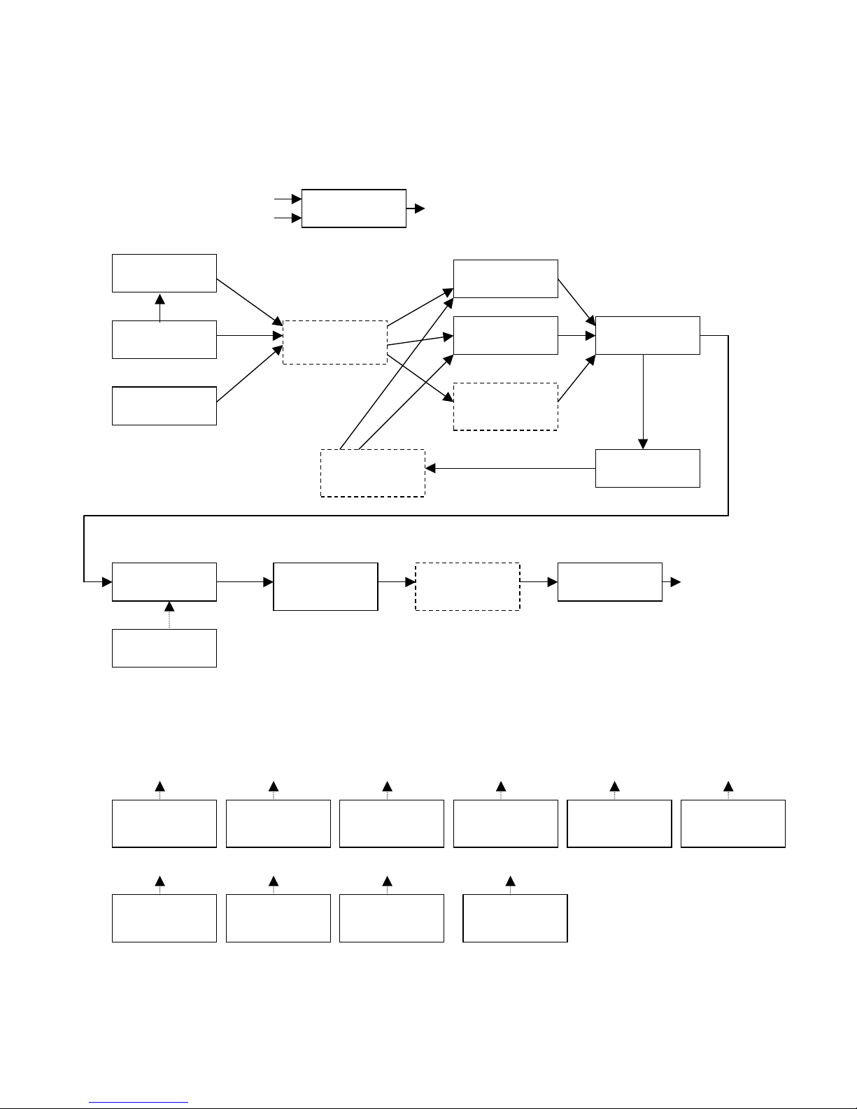
Anamono Internal Flow
Anamono Internal FlowAnamono Internal Flow
Anamono Internal Flow
Oscillator 1
sync
Oscillator 2
Ext Audio In
DSP Filter in
position 1
Analogue Filter
1
Analogue Filter
2
DSP Filter in
position 2
FeedBack
g-RAY Circuit
DSP Filter in
position 3
Amp
Amp Envelope
Granulator /
Delay
DSP Filter in
position 4
Analogue
Overdrive
MIDI Mod Envelope
Squared
Envelope
Modulator 1
LFO 1 LFO 2 Random
Modulator 1
Stepped
Modulator 2
Env Follower
Ring
Modulator
Osc1, Ext In, Ana VCF’s, Granu
Osc2, LFO1, Ana VCF’s, Granu
DSP filter, Ana VCF’s, Amp
Page 6
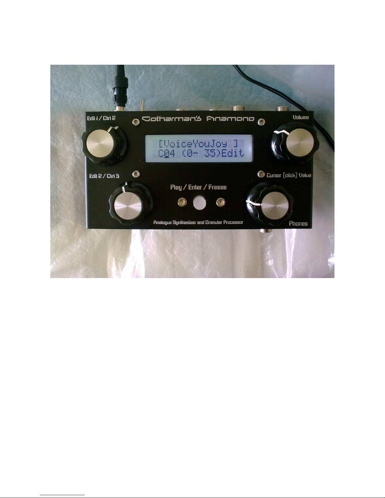
Anamono Front
Anamono FrontAnamono Front
Anamono Front
Edit1 / Ctrl 2: When on the preset select screen (the screen showing on the picture) and on the edit
page select screen, this knob transmits midi-controller 2 internally, and tweaks all
parameters, which has midi-controller 2 selected as modulation source, except if a
parameter are assigned to it on the ”ASSIGN EDIT 1” edit page.
When on a parameter edit screen, this knob adjusts the parameter showing at the left
of the screen.
Edit2 / Ctrl 3: When on the preset select screen (the screen showing on the picture) and on the edit
page select screen, this knob transmits midi-controller 3 internally, and tweaks all
parameters, which has midi-controller 3 selected as modulation source, except if a
parameter are assigned to it on the ”ASSIGN EDIT 2” edit page.
When on a parameter edit screen, this knob adjusts the parameter showing at the
middle of the screen.
Page 7

Play / Enter / Freeze: This knob starts and stops Modulator 1, if Modulator 1 trigger source = Play
or MIDI. It also works as a midi note on indicator – every time a midi note on, on the
selected midi-channel, are received it will light up.
When you select a new preset, it will start blinking, and you will have to push it to
confirm.
When on a granulator/delay edit page, this acts as a freeze knob, and freezes/unfreezes the granulator/delay every time it is pushed. It lights up, when freeze is active.
Cursor (click) value: This knob navigates around, changes preset, and changes various switch
functions on the parameter edit screens.
If the cursor is blinking, turning this knob will move the cursor. Pushing it will stop
the cursor from blinking, to change a value, or entering another screen.
If the cursor is not blinking, turning this knob, will change the value of the parameter,
where the cusor are located. Pushing it will get the cursor blinking to move it, or it
will enter another screen.
Volume: Changes the output volume on the audio and phones outputs.
Phones: Below the ”Phones” text on the front-side of Anamono, a phones output are located. It
is possible to connect a pair of stereo headphones to this.
Page 8
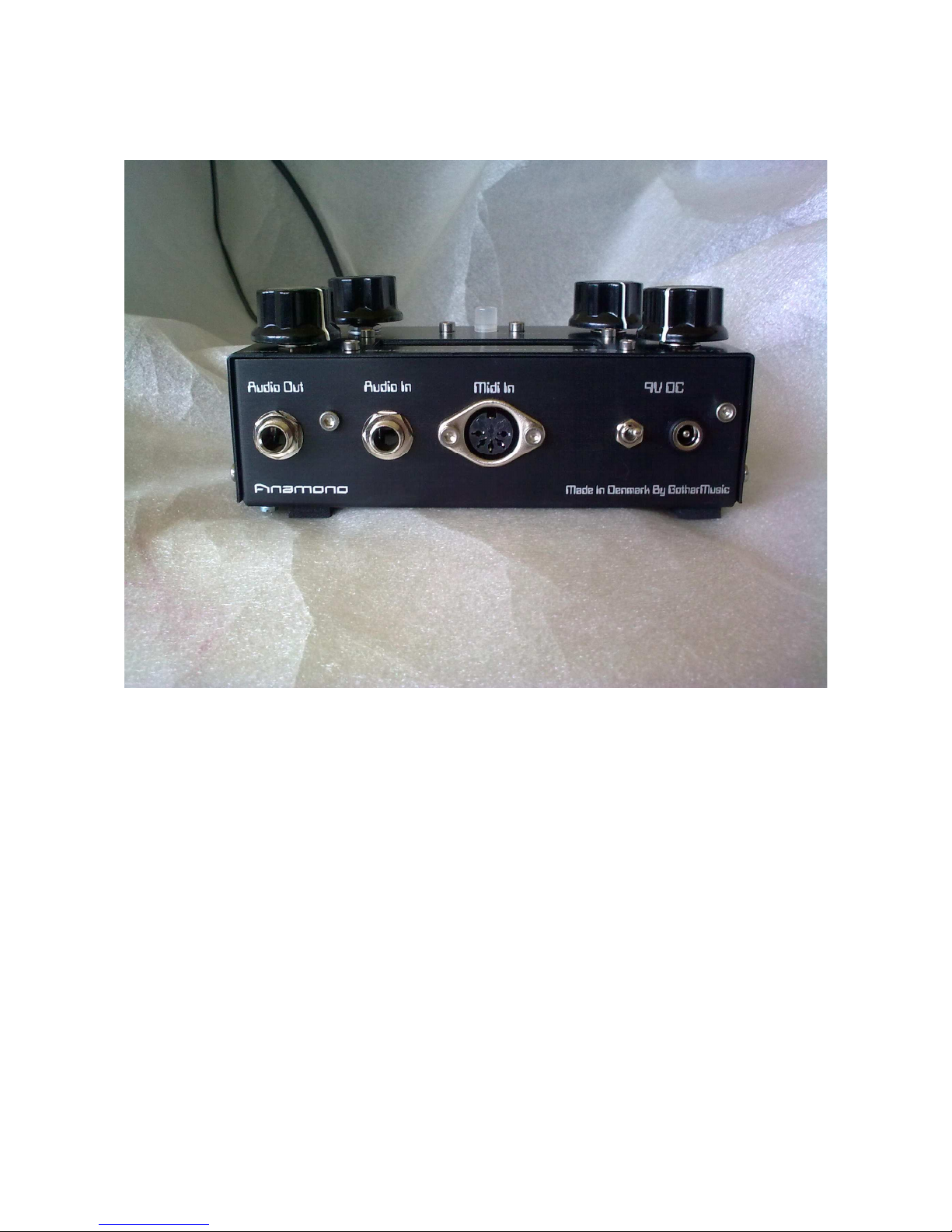
Anamono Back / Connections
Anamono Back / ConnectionsAnamono Back / Connections
Anamono Back / Connections
9VDC: Connect the supplied 9-12 VDC power adaptor to the socket. The switch near it are
the power on/off switch. If your Anamono wasn’t delivered with a power adaptor, or you
need to replace it, it has to be:
-A 9-12 V DC, min. 500 mA unregulated power adaptor with a 2.1 mm DC connector, with
the positive voltage in the middle.
MIDI in: Connect this to the MIDI out of a MIDI transmitting device (MIDI keyboard,
sequencer, computer or whatever).
Audio In jack: This is the external audio input of Anamono. Connect any line-level audio
source to this, to process it with Anamono’s powerful audio system.
Audio Out jack: This is a line output, and needs to be amplified. Connect it to an amplifier
or a mixer.
Page 9

How to get around
How to get aroundHow to get around
How to get around
Some main rules: If the cursor is blinking, you can move it by turning the
cursor(click)value encoder.
If the cursor is not blinking, you can change the value of the parameter the cursor are
located below, by turning the cursor(click)value encoder.
By pushing the cursor(click)value encoder, you change the cursor from blinking to notblinking and vice versa.
When the cursor is located under ”Edit”, on the preset select page, pushing the
cursor(click)value encoder, will enter the edit group select pages.
On the edit group select pages, pushing the cursor(click)value encoder, will enter the edit
parameters pages, except if the edit group page is ”EXIT”, then it will exit to the preset
select page.
If the cursor is located under an ”X”, pushing the cursor(click)value encoder, will exit to the
previous level.
Page 10

The Preset Select Page
The Preset Select PageThe Preset Select Page
The Preset Select Page
Every time you turn on your Anamono, it will for a short while write:
In it’s display.
Right after that, it will go to this screen:
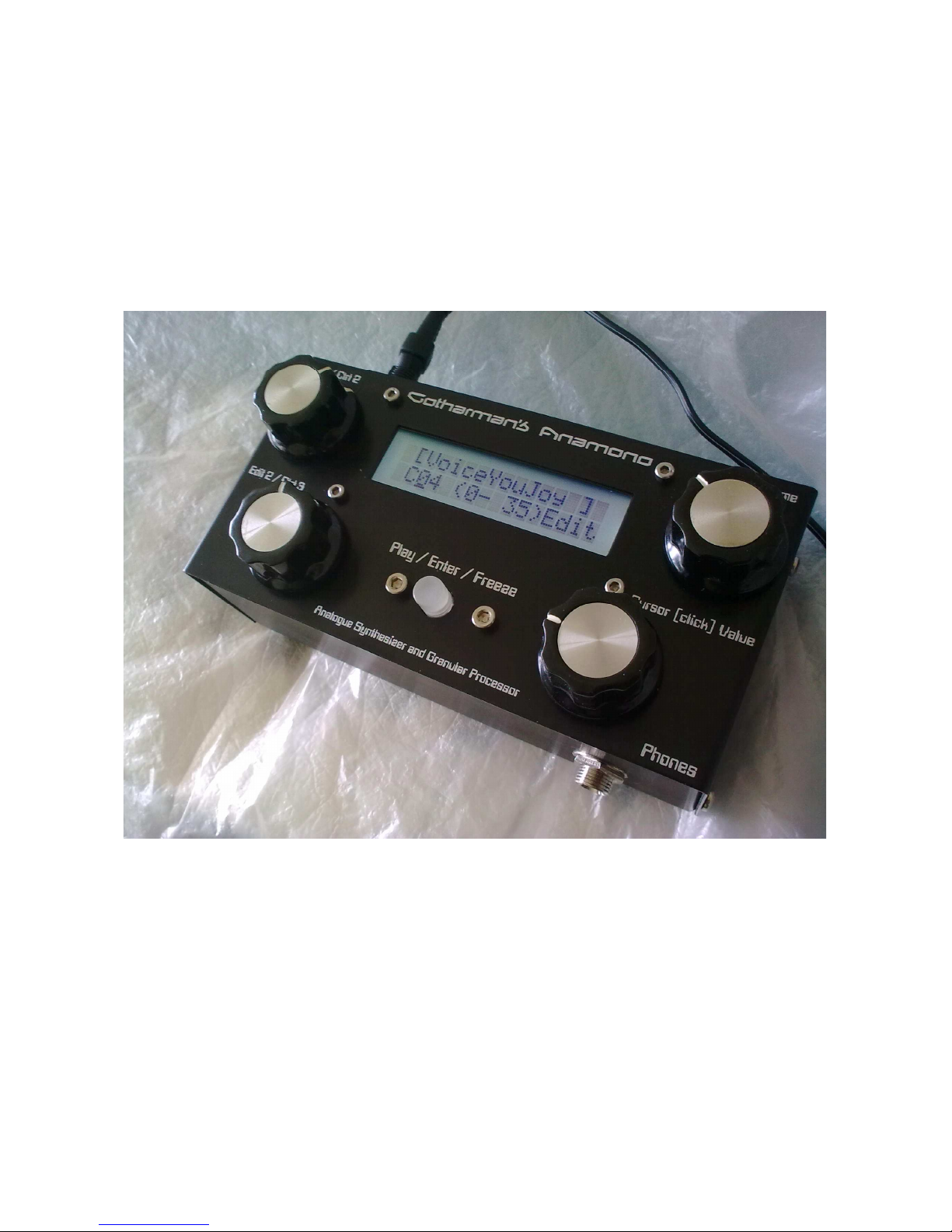
This is the Anamono main page.
On the top of the display it writes the name of the selected preset. It remembers what preset was
selected, when it was turned off, and goes to that preset when it is turned on again.
On the bottom of the display it writes the selected preset bank and number. Anamono has sixteen
banks (A-P) with each 16 sounds (256 in all). The number shown in paranthes, are the MIDI bank
select number (MIDI ctrl 32) followed by a slash and the MIDI program change number you will
have to transmit to Anamono, for selecting this preset, from an external MIDI-device.
As default, when entering the preset select page, the cursor is located under the preset number
select, so you immediately can select a preset. It is also possible to locate the cursor under the bank
select letter, or ”Edit”, if you wish to enter the edit pages.
To change preset: If the cursor is not blinking, push the cursor(click)value encoder, to make the
cursor blink. Rotate the cursor(click)value encoder in either direction to place the cursor under the
letter, if you want to change the bank number, or the number if you want to change the preset
number. Push the cursor(click)value encoder, so the cursor is not blinking. Rotate the
cursor(click)value encoder to select the preset you want. It will write the preset name in the top of
the display. The play/enter/freeze knob will now start to blink. Push the play/enter/freeze knob to
confirm change to the selected preset.
Gotharman’s
AnaMoNO
[VoiceYouJoy ]
A01 (0- 0) Edit
Page 11

The Edit Pages
The Edit PagesThe Edit Pages
The Edit Pages
NOTICE: The edits you do, are not automatically stored in memory. If you would like to keep your
creation, you wil have to SAVE the preset. How to do that, are explained later in this manual.
How to enter the edit pages from the preset select page:
If the cursor is not blinking, push the cursor(click)value encoder, so the cursor is blinking. Rotate
the cursor(click)value encoder until the cursor is located under ”Edit”. Push the cursor(click)value
encoder. Now this screen should appear:
If you now want to exit back to the preset select screen, rotate the cursor(click)value encoder, until
this screen appears:
Push the cursor(click)value encoder.
If you, on the other hand, wants to start edit and create some sounds, rotate the cursor(click)value
encoder. You can now select among various edit pages. Pushing the cursor(click)value encoder,
enters an edit page.
Inside an edit page, it might look like this:
By placing the cursor under the number in the upper left corner of the display, and pushing the
cursor(click)value encoder you can select among various edit pages in the selected edit group. By
placing the cursor under the ”X” and pushing the cursor(click)value encoder, you will exit to the
edit group select page.
The two parameters shown in the left and in the middle of the display are changed by rotating the
edit1 and edit2 knobs. The parameter to the right is changed by moving the cursor to it, and use the
cursor(click)value encoder.
1 OSC 1
EXIT
1 Wave. Mod. Sorc
X Saw + 0 Mod1
Page 12

Overview of the edit group pages:
Overview of the edit group pages:Overview of the edit group pages:
Overview of the edit group pages:
1 – Oscillator 1
2 – Oscillator 2
3 – Oscillator Mod
4 – DSP Filter
5 – Feedback
6 – Analogue Filters
7 – Amp (VCA)
8 – Granulator
9 – Mod Envelope
10 – Modulator 1
11 – Modulator 2
12 – LFO 1
13 – LFO 2
14 – Random
15 – Mod Keyboard
16 – MIDI
17 – Assign Edit 1
18 – Assign Edit 2
19 – Save Preset
20 – Exit (To preset select page)
Page 13
Anamono Modulation Sources
Anamono Modulation SourcesAnamono Modulation Sources
Anamono Modulation Sources
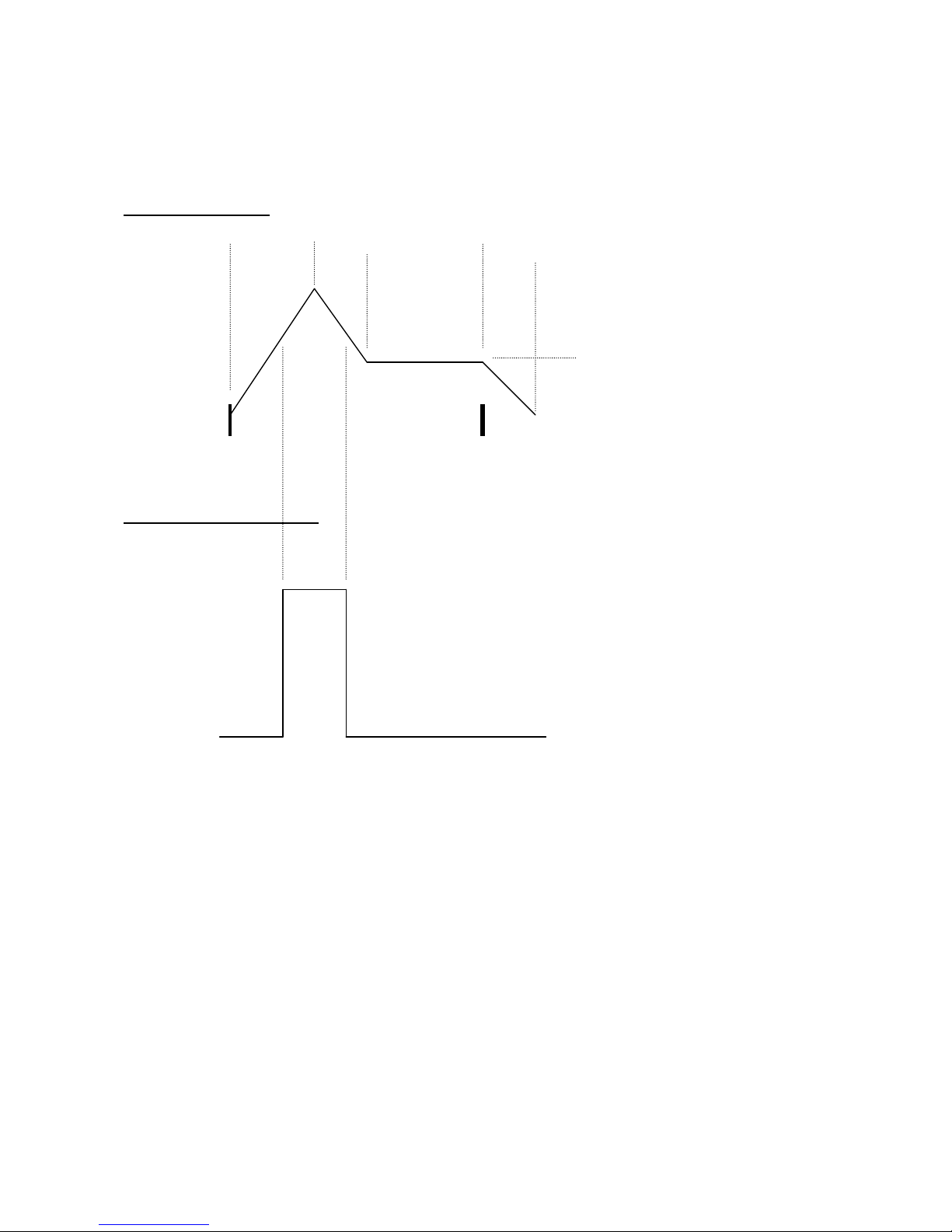
1 AMP/MOD ENV:
2 SQUARED MOD ENV:
A traditional ADSR envelope. It has 2 sets of settings, that can be morphed between,
using any modulator.
It also has a squared output: When the mod envelope has a value below half of it's
max value, this will be zero. When the mod envelope reaches above it's half value,
this will be at maximum value.
The amp section has it’s own ADSR envelope, that is controlling the total output
level, before the granulator and the overdrive, unless amp control = Folr. Then the
envelope follower controls the output level.
Note On
Note Off
Attack Time
Decay
Time
Release
Time
Sustain Level
Page 14
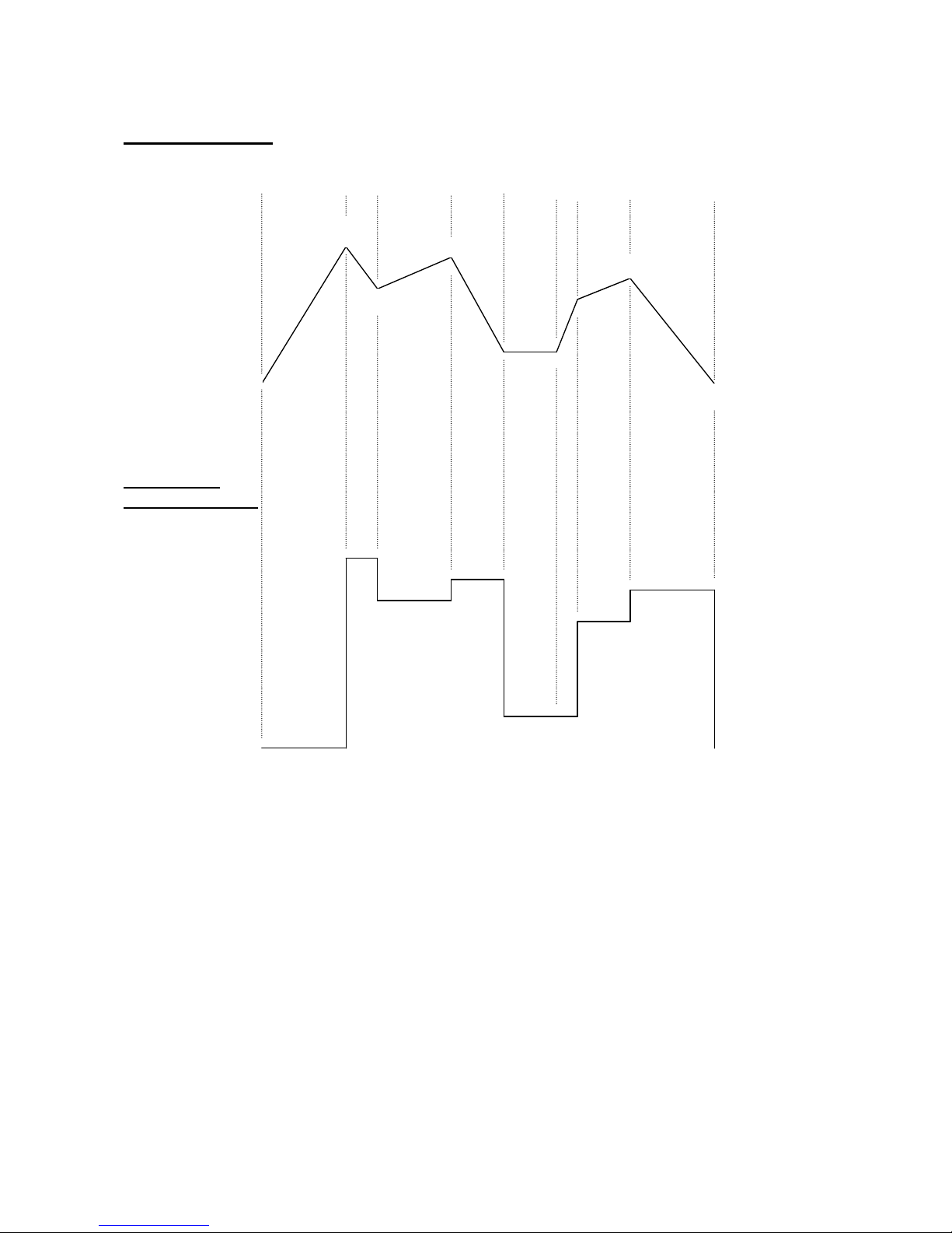
3 MODULATOR 1:
4 STEPPED
MODULATOR 1:
An 8 step very flexible modulator with a smooth output. Each step has a value
parameter, a time parameter (how long it will take to reach the next steps value), and
a selection of, if it will continue, sustain or loop, after this step. It has a flexible
trigger system: Off (freerun, no triggering), Key-reset (key triggered without retriggering), Key-trigger (key triggered with re-triggering), Key'ed (advances one step,
every time a note-on is received), Play (the play/enter knob starts and stops the
modulator) and MIDI (synced to MIDI-clock). It has 2 sets of settings, that can be
morphed between, using any modulator.
It also has a stepped output: Every time modulator 1 reaches a new step/value this is
updated. This can also be set up to put out note and gate values, and used as a
morphable step-sequencer.
L1
T1
L2
L3
L4
L5 L6
L7
L8
L1
T2 T3 T4 T5
T6
T7 T8
T: Times
L: Levels
Page 15
5 MODULATOR 2:
A 5-step shapable modulator. Step 1: delay time, step 2: rise time to full value, step 3:
hold time at full value, step 4: fall time to zero, step 5: hold time at zero value. Can
be key-triggered, looped or key-triggered and looped. It has 2 sets of settings, that can
be morphed between, using any modulator.
6 LFO 1
7 LFO 2
The LFO's waveforms are continuously variable from triangle to saw to square to
pulse. The LFO's can be both wave and rate-modulated, using any modulator. Both
LFO's can also be key-synced, and LFO wave start-point can be adjusted.
8 Random Voltage
Each time it is triggered, it outputs a new random value. Trigger sources are: LFO1,
LFO2 or key.
9 Random Pulse
A squared version of the random voltage with adjustable pw. When the random
voltage puts out a value above the pw, the output of this will be zero. When the
random voltage puts out a value below the pw, the output of this will be max.
T1 T2 T3 T4 T5
Page 16

10 Mod Kybd
The last received note on value are converted into a control level, using two
parameters: Offset (at what note value, will the modulation start) and spread (makes
the control curve more steep, at higher values).
11 Velo
The last received note on velocity value.
12 Env Folr
The audio signal present on the external audio input converted to a controller shape.
With adjustable smoothing.
13 MIDI Ctrl 1
14 MIDI Ctrl 2
15 MIDI Ctrl 3
16 MIDI Ctrl 4
The last received values from these four controllers or from edit knob 1 (ctrl 2) or 2
(ctrl 3). If edit knob 1 and 2 are assigned to a parameter in the assign section, MIDI
controller 2 and 3 will also be assigned to these, and ignored as modulation sources.
Page 17

Explanation Of The Edit
Explanation Of The EditExplanation Of The Edit
Explanation Of The Edit
Pages
PagesPages
Pages
The Oscillator 1 and 2 Pages
Anamono does have separate settings for oscillator 1 and 2, but since these settings are equal,
except for the keyboard on/off parameter, which only affects oscillator 2, they are both explained in
this one section.
The oscillators in Anamono are, together with the external audio input if wanted, creating the basic
building block for the sound. It is also the osillators, that dictates the basic pitch of the sound.
All Anamono waveforms has a certain number of harmonics. The sound is shaped by filtering out
some of these harmonics, using the analogue and digital filters, and by adding other harmonics,
using the ring modulator, oscillator sync and the analogue overdrive.
The oscillators waveforms are continiously variable from sine to triangle to saw to square to noise.
The wave-shaping can be modulated from all 16 modulation sources. All waveforms can be
pulsewidth and pitch-modulated.
Edit 1 – Oscillator wave shape: Value 0 to 255, 0: sine, 64: triangle, 128: saw, 192: square, 255:
noise.
Edit 2 – Oscillator wave shape modulation: Value –128 to +127. A negative value inverts the
modulation source.
Encoder - Oscillator wave shape modulation source: Value: Any of the 16 modulation sources.
1 OSC 1
1 Wave. Mod. Sorc
X Saw + 0 Mod1
2 OSC 2
Page 18

Edit 1 – Waveform pulse width: Value 0 to 255.
Edit 2 – Pulse width modulation: Value –128 to +127. A negative value inverts the modulation
source.
Encoder – Pulse width modulation source: Value: Any of the 16 modulation sources.
Pw does something different on each waveform:
Sine: A pure sine are a pure wave, without any harmonics. When pw is ”0”, the sinewave is pure.
The more Pw is turned up, the more the top of the sinewave is flattened out, to introduce extra
harmonics.
Triangle: When Pw is zero, a pure triangle is generated. As Pw is turned up, the triangle is
amplified more and more, but instead of clipping the waveform, it wraps the signal above maximum
over the zero point, and creates a totally different waveform.
Saw: When Pw is zero, a pure saw wave is generated. As Pw is turned up, it starts to sound more
and more like a synced sawtooth, with the sync pitch getting more and more detuned.
Square: When Pw is zero, it generates a symmetrical square wave with pulsewidth 50% / 50%. The
more Pw is turned up, the more unsymmetrical it gets, and at max value the pulsewidth is 100% /
0%.
Noise: Pw adjusts noise intensity.
2 Pw . Mod. Sorc
X 0 + 0 Env
Page 19

Edit 1 – Tune: Tunes the oscillator in semitone steps.
Edit 2 – Fine: Fine tuning of the oscillator.
Encoder – Kybd –Oscillator 2 only: Oscillator 2 keyboard pitch control on/off.
Edit 1 – Pitch modulation: Value –128 to +127. A negative value inverts the modulator.
Edit 2 – Pitch modulation source: Value: Any of the 16 modulation sources.
Encoder – Pitch modulation level source: Selects a source, that modulates the level of the pitch
modulation. Value: Off, first 15 modulation sources.
3 Tune. Fine. Kybd
X + 0 0 On
4 Mod. Sorc. Levl
X +127 Env Off
Page 20

The Oscillator Mod Pages
This section controls the common oscillator modulation: Portamento, sync, pitchbend range and
ring modulator.
Portamento creates a ”sliding” pitch effect, between two different notes.
Sync syncronizes the pitch of oscillator 2 to the pitch of oscillator 1. Every time the oscillator 1
waveform has reached a complete cycle (i.e. played back it’s waveform one time), it sends out a
syncronizing signal to oscillator 2, which is then resettted. If the frequency of oscillator 1 and 2 are
not equal, oscillator 2 will be reset at a point where it wouldn’t normally be reset, and this will
create the metallic sounding ”extra” frequency on top of the oscillator 2 waveform. The same effect
can be obtained by choosing waveform: saw, and adjust the pw, but now that Anamono has real
sync, this effect can be obtained on all waveforms.
The ring modulator takes the sum and the difference of the 2 signals present on it inputs, and puts
that signal out on the selected destination. This will add harmonic sidebands to the signals.
Depending on the waveforms and frequencies of the input signals, this will create a signal ranging
from metallic to ringing.
Edit 1 – Portamento: Value 0 to 255. The higher the value of this parameter, the slower the
oscillators will ”slide” from one frequency to another, when hitting a key on a connected MIDI
keyboard. At value ”0”, there will be no sliding between notes – the oscillators pitch will
immediately change to the new value.
Encoder - Oscillator sync: Value: On/off. When on, oscillator 2 will syncronize to the frequency
of oscillator 1. If the frequency of oscillator 1 and 2 are not equal, the classic sync effect will be
created.
3 OSC MOD
1 Porta. Sync 2<1
X 0 Off
Page 21

Edit 1 – Ring Modulator input 1 source: Value: osc1, ext audio in, analogue filters output,
granulator output.
Edit 2 – Ring Modulator input 2 source: Value: osc2, LFO1, analogue filters output, granulator
output.
Edit 1 – Ring Modulator output destination: Select where in the signal chain, you want the
ringmodulated signal to appear. Value: Digital filter input, analogue filters input, amp section
(VCA) input.
Edit 2 – Ring Modulator volume: The output level of the ring modulated signal. Value: 0-255.
Edit 1 – Ring Modulator output level modulation: Value –128 to +127. A negative value inverts
the modulator.
Edit 2 – Ring Modulator output level modulation source: Value: Any of the 16 modulation
sources.
2 Rin1. Rin2. .
X osc1 osc2 .
3 Rout. Rvol. .
X Dvcf 255 .
4 Rout. Sorc. .
X +127 Env .
Page 22

Edit 1 – Bender: Adjusts how much incoming MIDI pitch bend messages will affect both of the
oscillators pitch. From 0 to 255 (about 12 semitones at maximum).
5 Bender. .
X 128 .
Page 23

The Dsp Filter Pages
Anamono has 3 filters in all, 2 analogue and one digital. This section describes the digital one. The
digital filter is created using digital signal processing (DSP). It can be placed in 4 different positions
(routing is done in the analogue filters section, described later in this manual):
-In serial connection with and before the analogue filters.
-In parallel connection with the analogue filters.
-In the g-RAY feedback.
-After the granulator/delay.
A filter shapes the sound, by removing certain harmonics from the source audio signal, and by
amplifying certain harmonics around the cutoff frequency point (using resonance).
Edit 1 – External audio input level: Value 0 to 255. Adjusts the level of the audio signal present
on the external audio input, going to the DSP filter input.
Edit 2 - Boost: Value: 0 to 255. Boost the DSP filter output signal, to make it stronger. Higher
settings might introduce clipping.
4 DSP FILTER
1 Inp . Boost .
X 67 24 .
Page 24

Edit 1 – Oscillator 1 / Analogue filters level: Value 0 to 255. Adjusts the level of oscillator 1,
going to the DSP filter input. Except when DSP filter routing = feedback or granulator. When
routing = feedback, this parameter adjust the level of the analogue filters output, going to the DSP
filter. When routing = granulator, this parameter does nothing.
Edit 2 – Oscillator 2 level: Value 0 to 255. Adjusts the level of oscillator 2, going to the DSP filter
input.
Edit 1 – DSP filter cutoff frequency: Value 0 to 255.
Edit 2 – DSP filter resonance: Value 0 to 255.
Encoder – DSP filter type: Choices are: BPF: band pass mode, LPF: low pass mode, HPF: high
pass mode, BP8: Sharp bandpass mode, ADD: add filter mode. The ”ADD” filter is not actually a
filter, since it doesn’t filter out any harmonic. Instead it amplifies the harmonics around the cutoff
point.
2 Osc1. Osc2. .
X 100 74 .
3 Cut . Reso. Type
X 255 66 bpf
Page 25

Edit 1 – DSP filter cutoff modulation A: Value –128 to +127. A negative value inverts the
modulator.
Edit 2 – DSP filter cutoff modulation source A: Value: Any of the 16 modulation sources.
Edit 1 – DSP filter cutoff modulation B: Value –128 to +127. A negative value inverts the
modulator.
Edit 2 – DSP filter cutoff modulation source B: Value: Any of the 16 modulation sources.
Edit 2 – Cutoff modulation B level source: Selects a source, that modulates the level of cutoff
modulation B. Value: Off, first 15 modulation sources.
4 CutA. Sorc. .
X + 0 env .
5 CutB. Sorc. .
X + 0 env .
6 ModB Level .
X Off .
Page 26

Edit 1 – DSP filter resonance modulation: Value –128 to +127. A negative value inverts the
modulator.
Edit 2 – DSP filter resonance modulation source: Value: Any of the 16 modulation sources.
7 Reso . Sorc. .
X + 0 env .
Page 27

The FeedBack Pages
Anamono’s analogue feedback circuit creates an audio feedback loop from the output of the
analogue filters or the granulator/delay, to the input of the analogue filters. Inside the feedback loop
are a new Gotharman creation called ”g-RAY”. This creates a kind of intermodulation on the
feedback signal, and makes it possible to create sounds similar to FM plus new and never before
heard sounds.
The feedback signal can be delayed, to create comb filter like effects, and it is also possible to place
the DSP filter inside the feedback loop, so only certain frequencies are fed back.
Edit 1 – FeedBack level: Value 0 to 255.
Edit 2 – FeedBack delay: Value: 0 to 255. The amount of time that the fed back signal will be
delayed. 0 = 0 mSec, 255 = 6.4 mSec.
Encoder – FeedBack mode: Values:
-Norm: Normal 1:1 feedback.
-Neg: 1:1 feedback with the signal inverted (a 180 degree
phase shift)
-Ultr: Boosted feedback.
-Uneg: Boosted feedback with the signal inverted (a 180
degree phase shift)
5 FEEDBACK
1 Feed . Dly. Mode
X 100 0 Norm
Page 28

Edit 1 – FeedBack modulation 1: Value –128 to +127. A negative value inverts the modulator.
Edit 2 – FeedBack delay modulation 1: Value –128 to +127. A negative value inverts the
modulator.
Encoder – FeedBack modulation source 1: Value: Any of the 16 modulation sources.
Edit 1 – FeedBack modulation 2: Value –128 to +127. A negative value inverts the modulator.
Edit 2 – FeedBack delay modulation 2: Value –128 to +127. A negative value inverts the
modulator.
Encoder – FeedBack modulation source 2: Value: Any of the 16 modulation sources.
Edit 2 – FeedBack modulation 2 level source: Selects a source, that modulates the level of
FeedBack modulation 2. Value: Off, first 15 modulation sources.
2 Feed . Dly. Sorc
X + 0 + 0 Env
3 Feed . Dly. Sorc
X + 0 + 0 Env
4 Mod2 Level .
X Off .
Page 29

Edit 1 – FeedBack source: VCF: Analogue filters output
Gran: Granulator/delay output
Edit 2 – g-RAY: Value: 0 to 3. Adjusts the amount of g-RAY intermodulation. 0: no g-RAY, 3:
max g-RAY.
5 From . gRAY. .
X VCF 3 .
Page 30

The Analogue Filters Pages
Anamono has 2 analogue filters connected in parallel to each other. Each filter can be adjusted and
controlled separately. In this one section, you make the adjustments for both filters.
One of the analogue filters has selectable mode – lowpass, bandpass, highpass or off, while the
other filter are always in bandpass mode.
A filter shapes the sound, by removing certain harmonics from the source audio signal, and by
amplifying certain harmonics around the cutoff frequency point (using resonance).
Edit 1 – DSP filter output level: Value: 0 to 255. If connection = serial: Adjusts the level of the
DSP filter, going to the analogue filters input. If connection = parallel, feed or gran: Adjusts the
output level of the DSP filter.
Edit 2 – External audio input level: Value 0 to 255. Adjusts the level of the audio signal present
on the external audio input, going to the analogue filters inputs.
Encoder – DSP filter connection: Values:
-ser: In serial connection with the analogue filters.
-par: In parallel connection with the analogue filters.
-fed: Placed inside the g-RAY feedback loop.
-grn: Placed after the granulator/delay.
6 ANALOG FILTERS
1 Dflt . Inp. Conn
X 88 0 ser
Page 31

Edit 1 – Oscillator 1 level: Value 0 to 255. Adjusts the level of oscillator 1, going to the analogue
filters inputs.
Edit 2 – Oscillator 2 level: Value 0 to 255. Adjusts the level of oscillator 2, going to the analogue
filters inputs.
Edit 1 – Analogue filter 1 cutoff frequency: Value 0 to 255.
Edit 2 – Analogue filter 1 resonance: Value 0 to 255.
Encoder – Analogue filter 1 type: Choices are: LPF: low pass mode, BPF: band pass mode, HPF:
high pass mode, Off.
Edit 1 – Analogue filter 2 cutoff frequency: Value 0 to 255. If you want to use only analogue
filter 1, put this control to zero, and make sure, that all 3 filter 2 cutoff modulation controls are on
zero too. Then filter 2 will make no sound.
Edit 2 – Analogue filter 2 resonance: Value 0 to 255.
Encoder – Analogue filter 2 type: Always BPF: band pass mode.
2 Osc1. Osc2. .
X 100 74 .
3 Cut1.Res1. Type
X 255 66 lpf
4 Cut2.Res2. Type
X 255 96 bpf
Page 32

Edit 1 – Analogue filter 1 cutoff modulation A: Value –128 to +127. A negative value inverts the
modulator.
Edit 2 – Analogue filter 2 cutoff modulation A: Value –128 to +127. A negative value inverts the
modulator.
Encoder – Analogue filters cutoff modulation source A: Value: Any of the 16 modulation
sources.
Edit 1 – Analogue filter 1 cutoff modulation B: Value –128 to +127. A negative value inverts the
modulator.
Edit 2 – Analogue filter 2 cutoff modulation B: Value –128 to +127. A negative value inverts the
modulator.
Encoder – Analogue filters cutoff modulation source B: Value: Any of the 16 modulation
sources.
5 Cu1A.Cu2A.Sorc
X + 0 + 0 Esqu
6 Cu1B.Cu2B.Sorc
X + 0 + 0 Env
Page 33

Edit 1 – Analogue filter 1 cutoff modulation C: Value –128 to +127. A negative value inverts the
modulator.
Edit 2 – Analogue filter 2 cutoff modulation C: Value –128 to +127. A negative value inverts the
modulator.
Encoder – Analogue filters cutoff modulation source C: Value: Any of the 16 modulation
sources.
Edit 2 – Analogue filters cutoff modulation C level source: Selects a source, that modulates the
level of cutoff modulation C. Value: Off, first 15 modulation sources.
Edit 1 – Analogue filter 1 resonance modulation: Value –128 to +127. A negative value inverts
the modulator.
Edit 2 – Analogue filter 2 resonance modulation: Value –128 to +127. A negative value inverts
the modulator.
Encoder – Analogue filters resonance modulation source: Value: Any of the 16 modulation
sources.
7 Cu1C.Cu2C.Sorc
X + 0 + 0 Env
8 ModC Level .
X Off .
9 Res1. Res2. Sorc
X + 0 + 0 Env
Page 34

Edit 1 – DSP filter output level modulation: Value –128 to +127. A negative value inverts the
modulator.
Edit 2 – DSP filter output level modulation source: Value: Any of the 16 modulation sources.
Edit 1 – Analogue filters output level: Value 0 to 255.
Edit 2 – Analogue filters output level modulation: Value –128 to +127. A negative value inverts
the modulator.
Encoder – Analogue filters output level modulation source: Value: Any of the 16 modulation
sources.
A Dflt . Sorc. .
X + 0 env .
B Outp. Mod. Sorc
X 255 + 0 Env
Page 35

The Analogue Amp (VCA) Pages
This is Anamono’s analogue output stage – Amp or VCA (voltage controlled amplifier).
This section controls the output level of the sound, and it is possible to add some gritty analogue
overdrive.
The main output level controllers are the amp envelope or the envelope follower (shaped after the
audio signal present on the external audio input) together with the drone (VCA offset) and volume
parameters. It is also possible to modulate both the output level and overdrive with all the other
modulation sources, but the main controllers has to have a higher value than zero. Else there will be
no output signal.
The amp envelope has 2 sets of settings, that can be morphed between, using any of the 16
modulators. It is re-triggered every time a new note-on is received, but if one key is held, while
another key is pressed and released, it will not re-trigger, when the second note is released. In that
way, it is possible to make it re-trigger or not, using playing techniques.
The amp section is located after the analogue filters and before the granulator/delay, in Anamono’s
audio chain.
Edit 1 – Amp envelope attack time 1: Value: 0 to 255. The higher the value, the slower the rise of
the sound, when a MIDI note on are received, will be. This value is only completely active, if the
morph control on AMP edit page 5 are in position zero, and morph modulation has the value
+ 0.
Edit 2 – Amp envelope decay time 1: Value 0 to 255. After the amp envelope has rised to it’s max
value during the attack time, it will decay to it’s sustain level. The higher the value, the slower it
will decay. This value is only completely active, if the morph control on AMP edit page 5 are
in position zero, and morph modulation has the value + 0.
7 AMP
1 A . D . .
X 0 20 .
Page 36

Edit 1 – Amp envelope sustain level 1: Value: 0 to 255. This is the level, the amp envelope will
decay to, during the decay time. As long as a MIDI note on is held, it will stay at this level. This
value is only completely active, if the morph control on AMP edit page 5 are in position zero,
and morph modulation has the value + 0.
Edit 2 – Amp envelope release time 1: Value 0 to 255. This adjusts the time it will take, for the
sound to fade out, after a MIDI note off has been received. The higher the value, the slower it will
fade out. This value is only completely active, if the morph control on AMP edit page 5 are in
position zero, and morph modulation has the value + 0.
Edit 1 – Amp envelope attack time 2: Value: 0 to 255. The higher the value, the slower the rise of
the sound, when a MIDI note on are received, will be. This value is only completely active, if the
morph control on AMP edit page 5 are in position 255.
Edit 2 – Amp envelope decay time 2: Value 0 to 255. After the amp envelope has rised to it’s max
value during the attack time, it will decay to it’s sustain level. The higher the value, the slower it
will decay. This value is only completely active, if the morph control on AMP edit page 5 are
in position 255.
2 S . R . .
X 255 20 .
3 A2 . D2 . .
X 0 20 .
Page 37

Edit 1 – Amp envelope sustain level 2: Value: 0 to 255. This is the level, the amp envelope will
decay to, during the decay time. As long as a MIDI note on is held, it will stay at this level. This
value is only completely active, if the morph control on AMP edit page 5 are in position 255.
Edit 2 – Amp envelope release time 2: Value 0 to 255. This adjusts the time it will take, for the
sound to fade out, after a MIDI note off has been received. The higher the value, the slower it will
fade out. This value is only completely active, if the morph control on AMP edit page 5 are in
position 255.
Edit 1 – Amp envelope morph control: Value 0 to 255. At value zero, the first set of envelope
settings are used, at value 255 the second set of envelope settings are used. At values 1 to 254 it
morphs between the first and the second settings.
Edit 2 – Amp envelope morph modulation: Value –128 to +127. A negative value inverts the
modulator.
Encoder – Amp envelope morph modulation source: Value: Any of the 16 modulation sources.
Edit 1 – Sound overall volume: Value: 0 to 255.
Edit 2 – Amp overdrive: Value 0 to 255. Adds a crunchy analogue overdrive to the sound. When
turning this up, you might want to turn the overall volume down. Else it will be quite noisy!
4 S2 . R2 . .
X 255 20 .
5 Mrph. Mod. Sorc
X 0 + 0 Env
6 Vol . Drive . .
X 255 20 .
Page 38

Edit 1 – Sound overall volume modulation: Value –128 to +127. A negative value inverts the
modulator.
Edit 2 – Sound overall volume modulation source: Value: Any of the 16 modulation sources.
Encoder – Sound overall volume modulation level source: Selects a source, that modulates the
level of the overall volume modulation. Value: Off, first 15 modulation sources.
Edit 1 – Analogue overdrive modulation: Value –128 to +127. A negative value inverts the
modulator.
Edit 2 – Analogue overdrive modulation source: Value: Any of the 16 modulation sources.
Edit 1 – Amp control: Values:
-env: The amp envelope controls the amp output.
-folr: The envelope follower controls the amp output.
Use the ”env” setting for ”normal” sounds, you play from a connected MIDI device, use the ”folr”
setting, if you are processing an external audio signal.
Edit 2 – Envelope follower smoothing:
Adjusts the smoothness of the envelope follower. At
setting ”0”, you get a very smooth envelope follower control signal, but when turning this control
up, it will get less and less smooth, and follow the input signal faster. At ”255” it’s almost audio
modulation.
7 Vmod. Sorc.Levl
X + 0 Env Off
8 Drive Mod. .
X + 0 env .
9 Ctrl. Smooth. .
X env 0 .
Page 39

Edit 1 – Amp drone: Value 0 to 255. An overall sound volume offset parameter, that keeps
Anamono’s output constantly open, regardsless of the amp envelope and envelope follower.
A Drone. .
X 0 .
Page 40

The Granulator / Delay effect Pages
This is Anamono’s digital effect processor. It can be either in granulator or delay mode.
The granulator cuts the incoming audio signal up in an adjustable number of fragments (or grains).
It is then possible to re-arrange the playback of these fragments (pieces of audio) using an, up to 16
step, re-arrange sequencer. It is also possible to either time-stretch or detune each step, to switch the
audio playback direction between forward and reverse, and to freeze the audio content using any
modulator. A feedback control is also applied. The re-arrange sequencer are continiously playing
back from step 1 to the step chosen as last step, and then from step 1 again. It can’t be resat or
triggered in any way.
The delay works simular to a fat tape delay with adjustable and controllable time, mix, feedback,
audio playback direction (forward/reverse) and audio freeze.
The granulator/delay are the last stage in Anamono’s audio chain, placed right after the analogue
amp, and just before the audio output, except if DSP filter connection is ”gran”, then the DSP filter
is placed between the granulator/delay and the audio outputs. The DSP filter only affects the
granulator/delay’s effected output, not the clean output.
The Play / Enter / freeze button: Pushing this, when on the granulator/delay edit pages, will
freeze/un-freeze the audio content of the effect. When lit, freeze is active.
Edit 1 – Granulator mode: Values:
-Gran: Granulator mode.
-Dly: Delay mode.
Edit 2 – Effect mix: Value: 0 to 255. 0 = only clean un-effected signal, 255 = only effected signal.
Encoder – Granulator re-arrange sequencer last step: Value: 1 to 16. The re-arrange sequencer
will play back from step 1 to last step, and then jump to step 1 and start over again.
8 GRANULATOR
1 Mode. Mix. Last
X Gran 36 16
Page 41

Edit 1 – Granulator/delay total time: Value: 0 to 255. Max time 1.5 second, minimum time 22,9
micro second.
Edit 2 – Granulator/delay total time fine adjust: Value: 0 to 255.
Encoder – Granulator number of fragments: Values: 1, 2, 4, 8, 16, 32, 64, 128. Adjusts how
many fragments (grains), the granulator will cut the incoming audio signal up in.
Edit 1 – Granulator/delay feedback: Value: 0 to 255. Adjusts how big a portion of the effected
signal will be fed back to the granulator/delay input.
Edit 2 – Granulator/delay playback direction: Values:
-Fwd: The normal forward playback mode
-Rvs: The effected signal will play back
backwards.
Encoder – Granulator re-arrange sequencer step mode:
Values:
-strc: Each step in the re-arrange sequencer can be time-stretched.
-pitc: Each step in the re-arrange sequencer can be de-tuned.
2 Time. Fine. Frgm
X 255 36 16
3 Feed. Dir . Mode
X 73 Fwd strc
Page 42

Edit 1 – Granulator/delay freeze modulation source: Selects a source, that modulates the freeze
on/off function. Value: Off, first 15 modulation sources.
Edit 2 – Granulator/delay playback direction modulation source: Selects a source, that
modulates the playback direction Fwd/Rvs. Value: Off, first 15 modulation sources.
Edit 1 – Granulator/delay time modulation: Value –128 to +127. A negative value inverts the
modulator.
Edit 2 – Granulator/delay mix modulation: Value –128 to +127. A negative value inverts the
modulator.
Encoder – Granulator/delay time and mix modulation source: Value: Any of the 16 modulation
sources.
Edit 1 – Granulator re-arrange sequencer crossfade: Value: 0 to 254. When turned up, this
makes transitions between the re-arrange sequencer steps more smooth. Useful for avoiding clicks.
4 Frez. Dir .
X Off Off .
5 Time. Mix. Sorc
X + 0 + 0 Env
6 Xfade. .
X 0 .
Page 43

Edit 1 – Granulator re-arrange sequencer step 1 fragment number: Value: 1 to 128. Selects
what fragment of the incoming audio signal, step 1 of the re-arrange sequencer will play back.
Edit 2 – Granulator re-arrange sequencer step 1 Stretch/detune: Value: -128 to +127. Timestretches or detunes the audio piece played back by step 1, depending on the setting: Mode strc/pitc
on granulator edit page 3.
Edit 1 – Granulator re-arrange sequencer step 2 fragment number: Value: 1 to 128. Selects
what fragment of the incoming audio signal, step 2 of the re-arrange sequencer will play back.
Edit 2 – Granulator re-arrange sequencer step 2 Stretch/detune: Value: -128 to +127. Timestretches or detunes the audio piece played back by step 2, depending on the setting: Mode strc/pitc
on granulator edit page 3.
Edit 1 – Granulator re-arrange sequencer step 3 fragment number: Value: 1 to 128. Selects
what fragment of the incoming audio signal, step 3 of the re-arrange sequencer will play back.
Edit 2 – Granulator re-arrange sequencer step 3 Stretch/detune: Value: -128 to +127. Timestretches or detunes the audio piece played back by step 3, depending on the setting: Mode strc/pitc
on granulator edit page 3.
7 St01.Tune. .
X 1 + 0 .
8 St02.Tune. .
X 1 + 0 .
9 St03.Tune. .
X 1 + 0 .
Page 44

Edit 1 – Granulator re-arrange sequencer step 4 fragment number: Value: 1 to 128. Selects
what fragment of the incoming audio signal, step 4 of the re-arrange sequencer will play back.
Edit 2 – Granulator re-arrange sequencer step 4 Stretch/detune: Value: -128 to +127. Timestretches or detunes the audio piece played back by step 4, depending on the setting: Mode strc/pitc
on granulator edit page 3.
Edit 1 – Granulator re-arrange sequencer step 5 fragment number: Value: 1 to 128. Selects
what fragment of the incoming audio signal, step 5 of the re-arrange sequencer will play back.
Edit 2 – Granulator re-arrange sequencer step 5 Stretch/detune: Value: -128 to +127. Timestretches or detunes the audio piece played back by step 5, depending on the setting: Mode strc/pitc
on granulator edit page 3.
Edit 1 – Granulator re-arrange sequencer step 6 fragment number: Value: 1 to 128. Selects
what fragment of the incoming audio signal, step 6 of the re-arrange sequencer will play back.
Edit 2 – Granulator re-arrange sequencer step 6 Stretch/detune: Value: -128 to +127. Timestretches or detunes the audio piece played back by step 6, depending on the setting: Mode strc/pitc
on granulator edit page 3.
A St04.Tune. .
X 1 + 0 .
B St05.Tune. .
X 1 + 0 .
C St06.Tune. .
X 1 + 0 .
Page 45

Edit 1 – Granulator re-arrange sequencer step 7 fragment number: Value: 1 to 128. Selects
what fragment of the incoming audio signal, step 7 of the re-arrange sequencer will play back.
Edit 2 – Granulator re-arrange sequencer step 7 Stretch/detune: Value: -128 to +127. Timestretches or detunes the audio piece played back by step 7, depending on the setting: Mode strc/pitc
on granulator edit page 3.
Edit 1 – Granulator re-arrange sequencer step 8 fragment number: Value: 1 to 128. Selects
what fragment of the incoming audio signal, step 8 of the re-arrange sequencer will play back.
Edit 2 – Granulator re-arrange sequencer step 8 Stretch/detune: Value: -128 to +127. Timestretches or detunes the audio piece played back by step 8, depending on the setting: Mode strc/pitc
on granulator edit page 3.
Edit 1 – Granulator re-arrange sequencer step 9 fragment number: Value: 1 to 128. Selects
what fragment of the incoming audio signal, step 9 of the re-arrange sequencer will play back.
Edit 2 – Granulator re-arrange sequencer step 9 Stretch/detune: Value: -128 to +127. Timestretches or detunes the audio piece played back by step 9, depending on the setting: Mode strc/pitc
on granulator edit page 3.
D St07.Tune. .
X 1 + 0 .
E St08.Tune. .
X 1 + 0 .
F St09.Tune. .
X 1 + 0 .
Page 46

Edit 1 – Granulator re-arrange sequencer step 10 fragment number: Value: 1 to 128. Selects
what fragment of the incoming audio signal, step 10 of the re-arrange sequencer will play back.
Edit 2 – Granulator re-arrange sequencer step 10 Stretch/detune: Value: -128 to +127. Timestretches or detunes the audio piece played back by step 10, depending on the setting: Mode
strc/pitc on granulator edit page 3.
Edit 1 – Granulator re-arrange sequencer step 11 fragment number: Value: 1 to 128. Selects
what fragment of the incoming audio signal, step 11 of the re-arrange sequencer will play back.
Edit 2 – Granulator re-arrange sequencer step 11 Stretch/detune: Value: -128 to +127. Timestretches or detunes the audio piece played back by step 11, depending on the setting: Mode
strc/pitc on granulator edit page 3.
Edit 1 – Granulator re-arrange sequencer step 12 fragment number: Value: 1 to 128. Selects
what fragment of the incoming audio signal, step 12 of the re-arrange sequencer will play back.
Edit 2 – Granulator re-arrange sequencer step 12 Stretch/detune: Value: -128 to +127. Timestretches or detunes the audio piece played back by step 12, depending on the setting: Mode
strc/pitc on granulator edit page 3.
G St10.Tune. .
X 1 + 0 .
H St11.Tune. .
X 1 + 0 .
I St12.Tune. .
X 1 + 0 .
Page 47

Edit 1 – Granulator re-arrange sequencer step 13 fragment number: Value: 1 to 128. Selects
what fragment of the incoming audio signal, step 13 of the re-arrange sequencer will play back.
Edit 2 – Granulator re-arrange sequencer step 13 Stretch/detune: Value: -128 to +127. Timestretches or detunes the audio piece played back by step 13, depending on the setting: Mode
strc/pitc on granulator edit page 3.
Edit 1 – Granulator re-arrange sequencer step 14 fragment number: Value: 1 to 128. Selects
what fragment of the incoming audio signal, step 14 of the re-arrange sequencer will play back.
Edit 2 – Granulator re-arrange sequencer step 14 Stretch/detune: Value: -128 to +127. Timestretches or detunes the audio piece played back by step 14, depending on the setting: Mode
strc/pitc on granulator edit page 3.
Edit 1 – Granulator re-arrange sequencer step 15 fragment number: Value: 1 to 128. Selects
what fragment of the incoming audio signal, step 15 of the re-arrange sequencer will play back.
Edit 2 – Granulator re-arrange sequencer step 15 Stretch/detune: Value: -128 to +127. Timestretches or detunes the audio piece played back by step 15, depending on the setting: Mode
strc/pitc on granulator edit page 3.
J St13.Tune. .
X 1 + 0 .
K St14.Tune. .
X 1 + 0 .
L St15.Tune. .
X 1 + 0 .
Page 48

Edit 1 – Granulator re-arrange sequencer step 16 fragment number: Value: 1 to 128. Selects
what fragment of the incoming audio signal, step 16 of the re-arrange sequencer will play back.
Edit 2 – Granulator re-arrange sequencer step 16 Stretch/detune: Value: -128 to +127. Timestretches or detunes the audio piece played back by step 16, depending on the setting: Mode
strc/pitc on granulator edit page 3.
M St16.Tune. .
X 1 + 0 .
Page 49

The Modulation Envelope Pages
1 AMP/MOD ENV:
2 SQUARED MOD ENV:
A traditional ADSR envelope. It has 2 sets of settings, that can be morphed between, using any
modulator.
It also has a second squared output to the modulation bus: When the mod envelope has a value
below half of it's max value, this will be zero. When the mod envelope reaches above it's half value,
this will be at maximum value.
9 MOD ENV
Note On
Note Off
Attack Time
Decay
Time
Release
Time
Sustain Level
Page 50

Edit 1 – Mod envelope attack time 1: Value: 0 to 255. The higher the value, the slower the rise of
the sound, when a MIDI note on are received, will be. This value is only completely active, if the
morph control on MOD ENV edit page 5 are in position zero, and morph modulation has the
value + 0.
Edit 2 – Mod envelope decay time 1: Value 0 to 255. After the amp envelope has rised to it’s max
value during the attack time, it will decay to it’s sustain level. The higher the value, the slower it
will decay. This value is only completely active, if the morph control on MOD ENV edit page 5
are in position zero, and morph modulation has the value + 0.
Edit 1 – Mod envelope sustain level 1: Value: 0 to 255. This is the level, the amp envelope will
decay to, during the decay time. As long as a MIDI note on is held, it will stay at this level. This
value is only completely active, if the morph control on MOD ENV edit page 5 are in position
zero, and morph modulation has the value + 0.
Edit 2 – Mod envelope release time 1: Value 0 to 255. This adjusts the time it will take, for the
sound to fade out, after a MIDI note off has been received. The higher the value, the slower it will
fade out. This value is only completely active, if the morph control on MOD ENV edit page 5
are in position zero, and morph modulation has the value + 0.
1 A . D . .
X 0 20 .
2 S . R . .
X 255 20 .
Page 51

Edit 1 – Mod envelope attack time 2: Value: 0 to 255. The higher the value, the slower the rise of
the sound, when a MIDI note on are received, will be. This value is only completely active, if the
morph control on MOD ENV edit page 5 are in position 255.
Edit 2 – Mod envelope decay time 2: Value 0 to 255. After the amp envelope has rised to it’s max
value during the attack time, it will decay to it’s sustain level. The higher the value, the slower it
will decay. This value is only completely active, if the morph control on MOD ENV edit page 5
are in position 255.
Edit 1 – Mod envelope sustain level 2: Value: 0 to 255. This is the level, the amp envelope will
decay to, during the decay time. As long as a MIDI note on is held, it will stay at this level. This
value is only completely active, if the morph control on MOD ENV edit page 5 are in position
255.
Edit 2 – Mod envelope release time 2: Value 0 to 255. This adjusts the time it will take, for the
sound to fade out, after a MIDI note off has been received. The higher the value, the slower it will
fade out. This value is only completely active, if the morph control on MOD ENV edit page 5
are in position 255.
3 A2 . D2 . .
X 0 20 .
4 S2 . R2 . .
X 255 20 .
Page 52

Edit 1 – Mod envelope morph control: Value 0 to 255. At value zero, the first set of envelope
settings are used, at value 255 the second set of envelope settings are used. At values 1 to 254 it
morphs between the first and the second settings.
Edit 2 – Mod envelope morph modulation: Value –128 to +127. A negative value inverts the
modulator.
Encoder – Mod envelope morph modulation source: Value: Any of the 16 modulation sources.
5 Mrph. Mod. Sorc
X 0 + 0 Env
Page 53

The Modulator 1 Pages
3 MODULATOR 1:
4 STEPPED
MODULATOR 1:
An 8 step very flexible modulator with a smooth output. Each step has a value parameter, a time
parameter (how long it will take to reach the next steps value), and a selection of, if it will continue,
sustain or loop, after this step. It has a flexible trigger system: Off (freerun, no triggering), Keyreset (key triggered without re-triggering), Key-trigger (key triggered with re-triggering), Key'ed
10 MODULATOR 1
L1
T1
L2
L3
L4
L5 L6
L7
L8
L1
T2 T3 T4 T5
T6
T7 T8
T: Times
L: Levels
Page 54

(advances one step, every time a note-on is received), Play (the play/enter knob starts and stops the
modulator) and MIDI (synced to MIDI-clock). It has 2 sets of settings, the ”normal” settings and the
”b” settings, that can be morphed between, using any modulator.
It also has a second stepped output to the modulation bus: Every time modulator 1 reaches a new
step/value this is updated. This can also be set up to put out note and gate values, and used as a
morphable step-sequencer.
Edit 1 – Modulator 1 trigger mode:
Values:
-Off: Modulator 1 is running continiously and looped.
-Krst: Single triggered key reset. When a note on are received, and no other notes are held,
modulator 1 will reset to step 1 and thereafter loop. If other keys are held, when receiving a note on,
it will not reset.
-Ktrg: Multi triggered key reset. Every time a note on are received, modulator 1 will reset to step 1.
-Keyd: Every time a note on are received, it will advance one step, and loop that single step, until
the next note on are received.
-Play: When the Play/Enter/Freeze knob are pushed, so it is lit, modulator 1 will reset to step 1 and
thereafter continiously loop, until the Play/Enter/freeze knob are pushed again. Then it will stop.
-Midi: When a MIDI start command are received, modulator 1 will reset to step 1 and thereafter
loop continiously, synced to MIDI clock, until a MIDI stop command are received. In this mode it
can also be started and stopped by pushing the Play/Enter/Freeze knob, as long as a MIDI clock are
present.
Edit 2 – MIDI clock divide: Value: 1 to 256. A divisor that divides the MIDI clock used if trigger
mode = Midi.
Encoder – Stepped modulator 1 note output: Value: Off/On. If this is on, the stepped output of
modulator 1 will send note values to the 2 oscillators and key triggers to the envelopes, modulator
2, the LFO’s and random. Kind of like an analogue sequencer with a few differences.
1 Trig. Cdiv. Note
X Off 12 Off
Page 55

Edit 1 – Modulator 1 step 1 level: Value: 0 to 255. This value is only completely active, if the
morph control on Modulator 1 edit page I are in position zero, and morph modulation has the
value + 0.
Edit 2 – Modulator 1 step 1 Time: Value: 0 to 255. The time it will take to reach the value of the
next step. This value is only completely active, if the morph control on Modulator 1 edit page I
are in position zero, and morph modulation has the value + 0.
Encoder – Modulator 1 step 1 Will: Determines what Modulator 1 will do, after step 1 has been
executed. Possibilities are:
-Sust: It will sustain, and not loop, with this steps value, until it is re-triggered, then it will reset to
step 1.
-Cont: It will continue to the next step.
-Loop: It will loop – reset to step 1.
Edit 1 – Modulator 1 step 2 level: Value: 0 to 255. This value is only completely active, if the
morph control on Modulator 1 edit page I are in position zero, and morph modulation has the
value + 0.
Edit 2 – Modulator 1 step 2 Time: Value: 0 to 255. The time it will take to reach the value of the
next step. This value is only completely active, if the morph control on Modulator 1 edit page I
are in position zero, and morph modulation has the value + 0.
Encoder – Modulator 1 step 2 Will: Determines what Modulator 1 will do, after step 2 has been
executed. Possibilities are:
-Sust: It will sustain, and not loop, with this steps value, until it is re-triggered, then it will reset to
step 1.
-Cont: It will continue to the next step.
-Loop: It will loop – reset to step 1.
2 Stp1. Time. Will
X 255 20 Cont
3 Stp2. Time. Will
X 0 0 Cont
Page 56

Edit 1 – Modulator 1 step 3 level: Value: 0 to 255. This value is only completely active, if the
morph control on Modulator 1 edit page I are in position zero, and morph modulation has the
value + 0.
Edit 2 – Modulator 1 step 3 Time: Value: 0 to 255. The time it will take to reach the value of the
next step. This value is only completely active, if the morph control on Modulator 1 edit page I
are in position zero, and morph modulation has the value + 0.
Encoder – Modulator 1 step 3 Will: Determines what Modulator 1 will do, after step 3 has been
executed. Possibilities are:
-Sust: It will sustain, and not loop, with this steps value, until it is re-triggered, then it will reset to
step 1.
-Cont: It will continue to the next step.
-Loop: It will loop – reset to step 1.
Edit 1 – Modulator 1 step 4 level: Value: 0 to 255. This value is only completely active, if the
morph control on Modulator 1 edit page I are in position zero, and morph modulation has the
value + 0.
Edit 2 – Modulator 1 step 4 Time: Value: 0 to 255. The time it will take to reach the value of the
next step. This value is only completely active, if the morph control on Modulator 1 edit page I
are in position zero, and morph modulation has the value + 0.
Encoder – Modulator 1 step 4 Will: Determines what Modulator 1 will do, after step 4 has been
executed. Possibilities are:
-Sust: It will sustain, and not loop, with this steps value, until it is re-triggered, then it will reset to
step 1.
-Cont: It will continue to the next step.
-Loop: It will loop – reset to step 1.
4 Stp3. Time. Will
X 0 0 Cont
5 Stp4. Time. Will
X 0 0 Cont
Page 57

Edit 1 – Modulator 1 step 5 level: Value: 0 to 255. This value is only completely active, if the
morph control on Modulator 1 edit page I are in position zero, and morph modulation has the
value + 0.
Edit 2 – Modulator 1 step 5 Time: Value: 0 to 255. The time it will take to reach the value of the
next step. This value is only completely active, if the morph control on Modulator 1 edit page I
are in position zero, and morph modulation has the value + 0.
Encoder – Modulator 1 step 5 Will: Determines what Modulator 1 will do, after step 5 has been
executed. Possibilities are:
-Sust: It will sustain, and not loop, with this steps value, until it is re-triggered, then it will reset to
step 1.
-Cont: It will continue to the next step.
-Loop: It will loop – reset to step 1.
Edit 1 – Modulator 1 step 6 level: Value: 0 to 255. This value is only completely active, if the
morph control on Modulator 1 edit page I are in position zero, and morph modulation has the
value + 0.
Edit 2 – Modulator 1 step 6 Time: Value: 0 to 255. The time it will take to reach the value of the
next step. This value is only completely active, if the morph control on Modulator 1 edit page I
are in position zero, and morph modulation has the value + 0.
Encoder – Modulator 1 step 6 Will: Determines what Modulator 1 will do, after step 6 has been
executed. Possibilities are:
-Sust: It will sustain, and not loop, with this steps value, until it is re-triggered, then it will reset to
step 1.
-Cont: It will continue to the next step.
-Loop: It will loop – reset to step 1.
6 Stp5. Time. Will
X 0 0 Cont
7 Stp6. Time. Will
X 0 0 Cont
Page 58

Edit 1 – Modulator 1 step 7 level: Value: 0 to 255. This value is only completely active, if the
morph control on Modulator 1 edit page I are in position zero, and morph modulation has the
value + 0.
Edit 2 – Modulator 1 step 7 Time: Value: 0 to 255. The time it will take to reach the value of the
next step. This value is only completely active, if the morph control on Modulator 1 edit page I
are in position zero, and morph modulation has the value + 0.
Encoder – Modulator 1 step 7 Will: Determines what Modulator 1 will do, after step 7 has been
executed. Possibilities are:
-Sust: It will sustain, and not loop, with this steps value, until it is re-triggered, then it will reset to
step 1.
-Cont: It will continue to the next step.
-Loop: It will loop – reset to step 1.
Edit 1 – Modulator 1 step 8 level: Value: 0 to 255. This value is only completely active, if the
morph control on Modulator 1 edit page I are in position zero, and morph modulation has the
value + 0.
Edit 2 – Modulator 1 step 8 Time: Value: 0 to 255. The time it will take to reach the value of the
next step. This value is only completely active, if the morph control on Modulator 1 edit page I
are in position zero, and morph modulation has the value + 0.
Encoder – Modulator 1 step 8 Will: Determines what Modulator 1 will do, after step 8 has been
executed. Possibilities are:
-Sust: It will sustain, and not loop, with this steps value, until it is re-triggered, then it will reset to
step 1.
-Cont: It will loop – reset to step 1. This step cannot continue to the next step.
-Loop: It will loop – reset to step 1.
8 Stp7. Time. Will
X 0 0 Cont
9 Stp8. Time. Will
X 0 0 Cont
Page 59

Edit 1 – Modulator 1 step 1 b level: Value: 0 to 255. This value is only completely active, if the
morph control on Modulator 1 edit page I are in position 255.
Edit 2 – Modulator 1 step 1 b Time: Value: 0 to 255. The time it will take to reach the value of
the next step. This value is only completely active, if the morph control on Modulator 1 edit
page I are in position 255.
Encoder : Has no function.
Edit 1 – Modulator 1 step 2 b level: Value: 0 to 255. This value is only completely active, if the
morph control on Modulator 1 edit page I are in position 255.
Edit 2 – Modulator 1 step 2 b Time: Value: 0 to 255. The time it will take to reach the value of
the next step. This value is only completely active, if the morph control on Modulator 1 edit
page I are in position 255.
Encoder : Has no function.
A St1b. Time. Will
X 0 0 .
B St2b. Time. Will
X 0 0 .
Page 60

Edit 1 – Modulator 1 step 3 b level: Value: 0 to 255. This value is only completely active, if the
morph control on Modulator 1 edit page I are in position 255.
Edit 2 – Modulator 1 step 3 b Time: Value: 0 to 255. The time it will take to reach the value of
the next step. This value is only completely active, if the morph control on Modulator 1 edit
page I are in position 255.
Encoder : Has no function.
Edit 1 – Modulator 1 step 4 b level: Value: 0 to 255. This value is only completely active, if the
morph control on Modulator 1 edit page I are in position 255.
Edit 2 – Modulator 1 step 4 b Time: Value: 0 to 255. The time it will take to reach the value of
the next step. This value is only completely active, if the morph control on Modulator 1 edit
page I are in position 255.
Encoder : Has no function.
C St3b. Time. Will
X 0 0 .
D St4b. Time. Will
X 0 0 .
Page 61

Edit 1 – Modulator 1 step 5 b level: Value: 0 to 255. This value is only completely active, if the
morph control on Modulator 1 edit page I are in position 255.
Edit 2 – Modulator 1 step 5 b Time: Value: 0 to 255. The time it will take to reach the value of
the next step. This value is only completely active, if the morph control on Modulator 1 edit
page I are in position 255.
Encoder : Has no function.
Edit 1 – Modulator 1 step 6 b level: Value: 0 to 255. This value is only completely active, if the
morph control on Modulator 1 edit page I are in position 255.
Edit 2 – Modulator 1 step 6 b Time: Value: 0 to 255. The time it will take to reach the value of
the next step. This value is only completely active, if the morph control on Modulator 1 edit
page I are in position 255.
Encoder : Has no function.
E St5b. Time. Will
X 0 0 .
F St6b. Time. Will
X 0 0 .
Page 62

Edit 1 – Modulator 1 step 7 b level: Value: 0 to 255. This value is only completely active, if the
morph control on Modulator 1 edit page I are in position 255.
Edit 2 – Modulator 1 step 7 b Time: Value: 0 to 255. The time it will take to reach the value of
the next step. This value is only completely active, if the morph control on Modulator 1 edit
page I are in position 255.
Encoder : Has no function.
Edit 1 – Modulator 1 step 8 b level: Value: 0 to 255. This value is only completely active, if the
morph control on Modulator 1 edit page I are in position 255.
Edit 2 – Modulator 1 step 8 b Time: Value: 0 to 255. The time it will take to reach the value of
the next step. This value is only completely active, if the morph control on Modulator 1 edit
page I are in position 255.
Encoder : Has no function.
G St7b. Time. Will
X 0 0 .
H St8b. Time. Will
X 0 0 .
Page 63

Edit 1 – Modulator 1 morph control: Value 0 to 255. At value zero, the first set of modulator 1
settings are used, at value 255 the second ”b” set of modulator 1 settings are used. At values 1 to
254 it morphs between the first and the second settings.
Edit 2 – Modulator 1 morph modulation: Value –128 to +127. A negative value inverts the
modulator.
Encoder – Modulator 1 morph modulation source: Value: Any of the 16 modulation sources.
I Mrph. Mod. Sorc
X 0 + 0 Env
Page 64

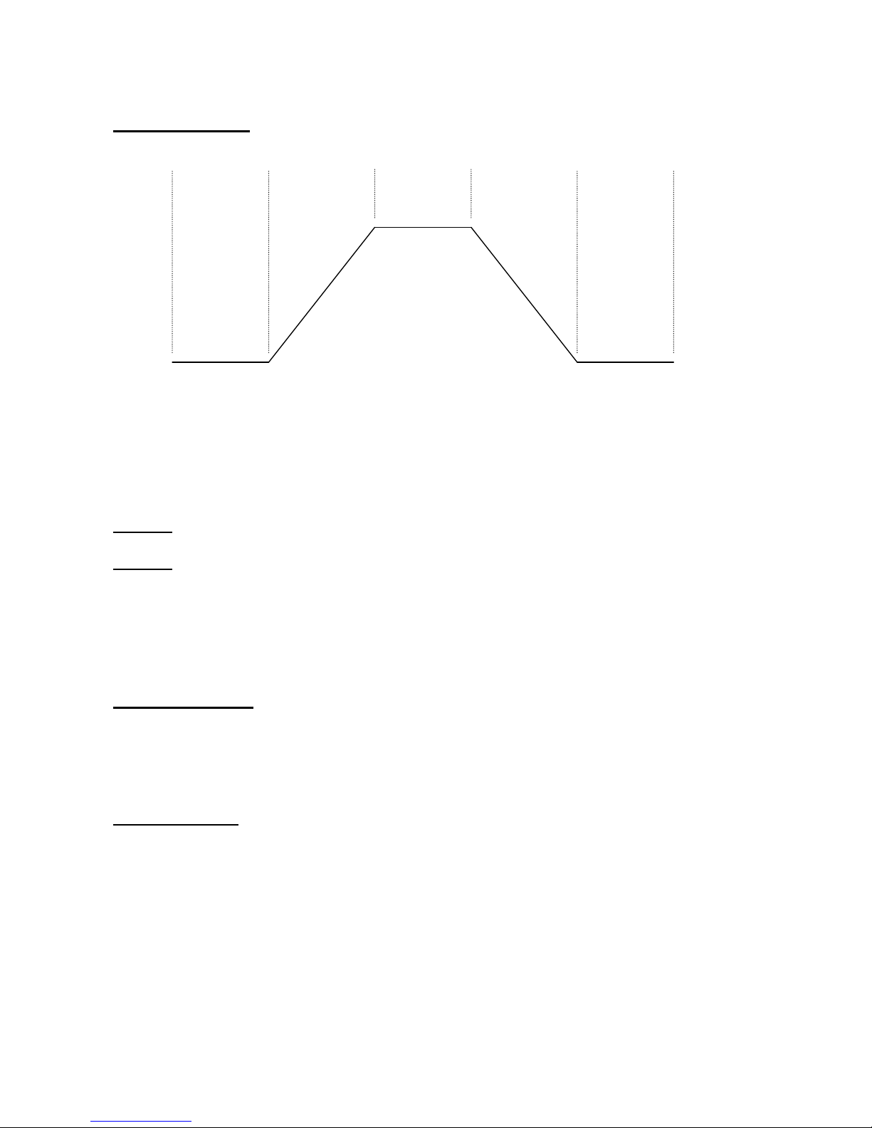
The Modulator 2 Pages
A 5-step shapable modulator. Step 1: delay time, step 2: rise time to full value, step 3:
hold time at full value, step 4: fall time to zero, step 5: hold time at zero value. Can
be key-triggered, looped or key-triggered and looped. It has 2 sets of settings, the
”normal” and the ”b” settings, that can be morphed between, using any modulator.
Edit 1 – Modulator 2 T1 delay time: Value: 0 to 255. The time from it is resat, until the rise time
starts. This value is only completely active, if the morph control on Modulator 2 edit page 7
are in position zero, and morph modulation has the value + 0.
Edit 2 – Modulator 2 Loop mode:
Values:
-Off: Modulator 2 is reset, when a note-on are received, excutes its 5 stages, ending with value
zero, and stays at that value, until it is re-triggered.
-On: Freerunning loop mode. It keeps repeating its 5 stages. No key triggering.
-Ktrg: Resets when a note on are received and thereafter it continiously loops, until it is re-
triggered.
11 MODULATOR 2
T1 T2 T3 T4 T5
1 T1 . Loop . .
X 0 Off .
Page 65

Edit 1 – Modulator 2 T2 rise time: Value: 0 to 255. The time it takes to rise to full value. This
value is only completely active, if the morph control on Modulator 2 edit page 7 are in
position zero, and morph modulation has the value + 0.
Edit 1 – Modulator 2 T3 hold time1: Value: 0 to 255. The time it will hold at full value. This
value is only completely active, if the morph control on Modulator 2 edit page 7 are in
position zero, and morph modulation has the value + 0.
Edit 1 – Modulator 2 T4 fall time: Value: 0 to 255. The time it takes to fall from full value to
zero. This value is only completely active, if the morph control on Modulator 2 edit page 7 are
in position zero, and morph modulation has the value + 0.
Edit 1 – Modulator 2 T5 hold time2: Value: 0 to 255. The time it will hold at value zero. This
value is only completely active, if the morph control on Modulator 2 edit page 7 are in
position zero, and morph modulation has the value + 0.
Edit 1 – Modulator 2 T1 b delay time: Value: 0 to 255. The time from it is resat, until the rise
time starts. This value is only completely active, if the morph control on Modulator 2 edit page
7 are in position 255.
2 T2 . T3 . .
X 0 0 .
3 T4 . T5 . .
X 0 0 .
4 T1b . . .
X 0 .
Page 66

Edit 1 – Modulator 2 T2 b rise time: Value: 0 to 255. The time it takes to rise to full value. This
value is only completely active, if the morph control on Modulator 2 edit page 7 are in
position 255.
Edit 1 – Modulator 2 T3 b hold time1: Value: 0 to 255. The time it will hold at full value. This
value is only completely active, if the morph control on Modulator 2 edit page 7 are in
position 255.
Edit 1 – Modulator 2 T4 b fall time: Value: 0 to 255. The time it takes to fall from full value to
zero. This value is only completely active, if the morph control on Modulator 2 edit page 7 are
in position 255.
Edit 1 – Modulator 2 T5 b hold time2: Value: 0 to 255. The time it will hold at value zero. This
value is only completely active, if the morph control on Modulator 2 edit page 7 are in
position 255.
5 T2b .T3b . .
X 0 0 .
6 T4b .T5b . .
X 0 0 .
Page 67

Edit 1 – Modulator 2 morph control: Value 0 to 255. At value zero, the first set of modulator 2
settings are used, at value 255 the second ”b” set of modulator 2 settings are used. At values 1 to
254 it morphs between the first and the second settings.
Edit 2 – Modulator 2 morph modulation: Value –128 to +127. A negative value inverts the
modulator.
Encoder – Modulator 2 morph modulation source: Value: Any of the 16 modulation sources.
7 Mrph. Mod. Sorc
X 0 + 0 Env
Page 68

The LFO 1 and LFO 2 Pages
Anamono’s 2 LFO’s are each has their own set of settings, but since they are equal,
both LFO’s are explained in this one chapter. The LFO's waveforms are continuously
variable from triangle to saw to square to pulse. The LFO's can be both wave and
rate-modulated, using any modulator. Both LFO's can also be key-synced, and LFO
wave start-point can be adjusted.
Edit 1 – LFO Rate: Value 0 to 255. Sets the speed of the LFO.
Edit 2 – LFO Rate modulation: Value –128 to +127. A negative value inverts the modulator.
Encoder – LFO Rate modulation source: Value: Any of the 16 modulation sources.
12 LFO 1
13 LFO 2
1 Rate. Rate Mod
X 0 + 0 Env
Page 69

Edit 1 – LFO wave shape: Value 0 to 255. Morphs between triangle (0), saw (64), square (128)
and pulse (255).
Edit 2 – LFO wave shape modulation: Value –128 to +127. A negative value inverts the
modulator.
Encoder – LFO wave shape modulation source: Value: Any of the 16 modulation sources.
Edit 1 – LFO key trigger: Value Off, 1 to 255. Off: The LFO is freerunning, and not key-
triggered. 1-255: The LFO is key-triggered. The value sets the LFO wave start position.
2 Wave.Wave Mod
X 0 + 0 Env
3 KeyTrig .
X Off .
Page 70

The Random Pages
Anamono’s random generator has 2 outputs to the modulation matrix:
Random Voltage:
Each time it is triggered, it outputs a new random value. Trigger sources are: LFO1,
LFO2 or key.
Random Pulse:
A squared version of the random voltage with adjustable pw. When the random
voltage puts out a value above the pw, the output of this will be zero. When the
random voltage puts out a value below the pw, the output of this will be max.
In this section adjustments for both output are made.
Edit 1 – Random pulse output Pw: Value 0 to 255.
Encoder – Random trigger: Values:
LFO1: Every time LFO1 restarts its cycle, a new random value will be outputted.
LFO2: Every time LFO2 restarts its cycle, a new random value will be outputted.
Key: Every time a MIDI note-on message are received, a new random value will be outputted.
14 RANDOM
1 PulsPw. Trig
X 128 LFO1
Page 71

The Modulation Keyboard Pages
The last received note on value are converted into a control level, using two
parameters: Offset (at what note value, will the modulation start) and spread (makes
the control curve more steep, at higher values). These possibilities are useful, if you
t.ex. don’t want keyboard modulation when playing the lowest key of your keyboard,
but wants full keyboard modulation on the highest key. If you don’t bother about this,
leave both settings at zero.
Edit 1 – Mod keyboard offset: Value 0 to 255. The incoming note-on value has to be higher than
the offset, to have any effect.
Edit 2 – Mod keyboard spread: Value 0 to 7. The higher value, the more steep the keyboard
modulation curve will be.
15 MOD KYBD
1 Offs.Sprd .
X 0 0 .
Page 72

The MIDI settings Pages
On this page, you can adjust the basic MIDI settings of Anamono.
Edit 1 – Basic MIDI channel: Value 1 to 16. This are the MIDI channel, Anamono will receive all
MIDI data on. For details regarding the MIDI information recognized by Anamono, see later in this
manual.
Edit 2 – NRPN controller receive mode: Values: 7b = 7 bit, 14b = 14 bit. Anamono can receive
NRPN controllers either without fine adjust (7 bit mode) or with fine adjust (14 bit mode). For
details regarding how Anamono recognizes NRPN controllers, see the parameter list section later in
this manual.
Encoder – MIDI controller set: Values: pri = primary controller set, sec = secondary controller
set. To allow the use of more possible MIDI controller numbers, Anamono has 2 sets of controllers.
It is also possible to switch between the primary and secondary controller set, using MIDI controller
65. For details regarding how Anamono recognizes MIDI controllers, see the parameter list section
later in this manual.
16 MIDI
1 Chan. Nrpn. Ctrl
X 01 7b pri
Page 73

The Assign Edit Knob Pages
As a default setting, edit knob 1 sends MIDI controller 2 and edit knob 2 sends MIDI controller 3
internally in Anamono, and controls all the parameters, which has MIDI controller 2 and 3 selected
as modulators. If you don’t want to mess around, assigning MIDI controller 2 or 3 to a specific
parameter, for live use for instance, it is possible on these edit pages, to assign any of Anamono’s
parameters to the edit knobs.
NOTE: When a parameter are assigned to one of the edit knobs, MIDI controller 2 and/or 3 are also
assigned to this parameter, and all parameters which has MIDI controller 2 or 3 selected as a
modulation source, will be ignored.
Encoder – Parameter group select:
The parameter group name writes in the top of the display, when you select a group.
Values:
0: MIDI controller 2/3 (default setting)
1: Oscillator 1
2: Oscillator 2
3: Oscillator Mod
4: DSP Filter
5: FeedBack
6: Analogue Filters
7: Amp
8: Granulator / Delay
9: Mod Envelope
10: Modulator 1
11: Modulator 2
12: LFO 1
17 ASSIGN EDIT 1
1 Ctrl 2 .
X Group 0
18 ASSIGN EDIT 2
Page 74

13: LFO 2
14: Random
15: Mod Keyboard
Encoder – Parameter select:
The parameter name writes in the top of the display, when you select it.
Values: Any parameter in the selected group.
2 Vcf Reso1 .
X Parameter 7
Page 75

The Save Preset Pages
Stores your sound/effect creation in any of Anamono’s 256 preset memory locations,
so you can recall it, when needed.
Use the Cursor(click)value encoder to select the location, where you want to save your sound, or
move it to the ”X” and push it if you regret. It will write the name of the taget location at the top of
the display or write <empty>, if no sound is previously stored in the selected location.
Push the Play/Enter/freeze knob to move to the next page:
Name your preset. Move the Cursor(click)value encoder to select the letters you want to change,
push it to change, or move it to the ”X” and push if you regret.
Pushing the Play/Enter knob stores the preset and exits save mode.
19 SAVE PRESET
[ Analogue ]
SAVE TO: C16 X
[ Analogue ]
X
Page 76

The Exit Page
Exit’s to the preset select page, when pushing cursor(click)value.
Exit
Page 77

AnamOno MIDI-implementation
Note-on’s and Note-off’s are received on the MIDI channel selected on the MIDI edit pages.
Pitch bend change are received on the MIDI channel selected on the MIDI edit pages.
Program change are received on the MIDI channel selected on the MIDI edit pages. Note, that it is
only possible to select 128 presets via MIDI program change. To select between banks A to H, or
banks I to P, you must use bank change.
Bank change (controller number 32) are received on the MIDI channel selected on the MIDI edit
pages. A value of 0 will select preset banks A to H. A value of 1 will select preset banks I to P. All
other values will be ignored.
MIDI Controllers are received on the MIDI channel selected on the MIDI edit pages. Controllers
1, 2, 3 and 4 are assignable as modulation sources for many of Anamono’s parameters. All other
controllers are hard-assigned to specific parameters. For details see the next section: Parameter List.
MIDI NRPN Controllers (Non-registrered parameter number) are received on the MIDI channel
selected on the MIDI edit pages. All Anamono’s parameters can be controlled with NRPN’s. For
details see the next section: Parameter List.
MIDI clock, start and stop are received only by Modulator 1, when it is in MIDI sync mode.
When a valid parameter MIDI or NRPN controller are received, the parameter
name and the received value shows in AnamOno’s display for about a second.
Ring Lvl 68_
Page 78

Parameter List
Parameter ListParameter List
Parameter List
And NRPN explanation
NRPN’s:
On this parameter list, there are an NRPN 99 (parameter MSB) and an NRPN 98 (parameter LSB)
number. These numbers indicates the NRPN parameter number of each of Anamono’s parameters.
All of these NRPN numbers are in hex format.
Anamono controlled in 7 bit NRPN mode:
When the NRPN parameter on the MIDI edit page are selected to be 7b (7 bit), Anamono needs the
following data to adjust a parameter:
-MIDI controller 99 (parameter MSB – see parameter list).
-MIDI controller 98 (parameter LSB – see parameter list).
-MIDI controller 6, a 7 bit value.
The parameter selected by MIDI controller 98 and 99 are immediately updated, when receiving the
MIDI controller 6 value, and Anamono will write the parameter name and value in its display for
about a second.
Anamono controlled in 14 bit NRPN mode:
When the NRPN parameter on the MIDI edit page are selected to be 14b (14 bit), Anamono needs
the following data to adjust a parameter:
-MIDI controller 99 (parameter MSB – see parameter list).
-MIDI controller 98 (parameter LSB – see parameter list).
-MIDI controller 6, a 1 bit value. Only the LSB bit of this value are used.
-MIDI controller 38, a 7 bit value, which sets the 7 LSB bits of the value.
The LSB bit from the controller 6 value and the 7 LSB bits from the controller 38 value, are
assembled to a complete 8 bit value, which Anamono needs for full range parameter control. The
LSB bit from ctrl 6, are the MSB bit of the final value.
The parameter selected by MIDI controller 98 and 99 are immediately updated, when receiving the
MIDI controller 38 value, and Anamono will write the parameter name and value in its display for
about a second. If it only receives the controller 6 value, nothing will happen in this mode.
Controller’s:
On many of the parameters there are also a MIDI controller number. This is the controller number,
which is hard-assigned to the specific parameter. Some of the controller numbers are prefixed with
”primary” or ”secondary”. This means, that the specific parameter are only controllable via MIDI if
the specified primary/secondary controller group are selected on the MIDI edit page.
Page 79

OSC 1
OSC 1OSC 1
OSC 1
Parameter Values MIDI ctrl NRPN 99 NRPN 98
Wave Morph from sine to
triangle to sawtooth
to square to noise.
8 00h 00h
Wave Mod -128 to +127
00h 01h
Wave Mod Source Select between the
16 modulation
sources.
00h 02h
PW –Waveform
Pulsewidth
0 to 255 –Does
something on all
waveforms.
9 00h 03h
PWM –Pulsewidth
Mod
-128 to +127
00h 04h
Pulsewidth Source Select between the
16 modulation
sources.
00h 05h
Tune -32 to +31 –In
semitone steps.
10 00h 06h
Fine Tune 0 to -255
11 00h 07h
Pitch Mod -128 to +127
00h 08h
Pitch Mod Source Select between the
16 modulation
sources.
00h 09h
Pitch Mod Level
Source
Select between
”Off” and 15 of the
modulation sources.
00h 0Ah
Page 80

OSC 2
OSC 2OSC 2
OSC 2
Parameter Values MIDI ctrl NRPN 99 NRPN 98
Wave Morph from sine to
triangle to sawtooth
to square to noise.
12 01h 00h
Wave Mod -128 to +127
01h 01h
Wave Mod Source Select between the
16 modulation
sources.
01h 02h
PW –Waveform
Pulsewidth
0 to 255 –Does
something on all
waveforms.
13 01h 03h
PWM –Pulsewidth
Mod
-128 to +127
01h 04h
Pulsewidth Source Select between the
16 modulation
sources.
01h 05h
Tune -32 to +31 –In
semitone steps.
14 01h 06h
Fine Tune 0 to -255
15 01h 07h
Keyboard On/Off
01h 08h
Pitch Mod -128 to +127
01h 09h
Pitch Mod Source Select between the
16 modulation
sources.
01h 0Ah
Pitch Mod Level
Source
Select between
”Off” and 15 of the
modulation sources.
01h 0Bh
Page 81

OSC MOD
OSC MODOSC MOD
OSC MOD
Parameter Values MIDI ctrl NRPN 99 NRPN 98
Portamento 0 to 255
5 02h 00h
Osc Sync 2<1 On/Off
02h 01h
Ring Modulator
Input 1
Osc1, Ext In,
Analogue Filters,
Granulator
02h 02h
Ring Modulator
Input 2
Osc2, LFO1,
Analogue Filters,
Granulator
02h 03h
Ring Modulator
Output
Digital Filter,
Analogue Filters,
VCA
02h 04h
Ring Modulator
Output Level
0 to 255
16 02h 05h
Ring Modulator
Output Modulation
-128 to +127
02h 06h
Ring Modulator
Output Modulation
Source
Select between the
16 modulation
sources.
02h 07h
Pitch Bend Amount 0 to 255
02h 08h
Page 82

DSP FILTER
DSP FILTERDSP FILTER
DSP FILTER
Parameter Values MIDI ctrl NRPN 99 NRPN 98
Ext Audio In Level 0 to 255
17 03h 00h
Boost 0 to 255
18 03h 01h
Osc 1 Level 0 to 255
19 03h 02h
Osc 2 Level 0 to 255
20 03h 03h
Cutoff 0 to 255
21 03h 04h
Resonance 0 to 255
22 03h 05h
Filter Type Bpf, Lpf, Hpf, Bp8,
Add.
23 03h 06h
Cutoff Mod A -128 to +127
03h 07h
Cutoff Mod A
Source
Select between the
16 modulation
sources.
03h 08h
Cutoff Mod B -128 to +127
03h 09h
Cutoff Mod B
Source
Select between the
16 modulation
sources.
03h 0Ah
Cutoff Mod B Level
Source
Select between
”Off” and 15 of the
modulation sources.
03h 0Bh
Resonance Mod -128 to +127
03h 0Ch
Resonance Mod
Source
Select between the
16 modulation
sources.
03h 0Dh
Page 83

FEEDBACK
FEEDBACKFEEDBACK
FEEDBACK
Parameter Values MIDI ctrl NRPN 99 NRPN 98
FeedBack 0 to 255
24 04h 00h
FeedBack Delay 0 to 255
25 04h 01h
FeedBack Mode Normal, Negative,
Ultra, Ultra Negative
26 04h 02h
FeedBack
Modulation 1
-128 to +127
04h 03h
FeedBack Delay
Modulation 1
-128 to +127
04h 04h
FeedBack
Modulation Source
1
Select between the
16 modulation
sources.
04h 05h
FeedBack
Modulation 2
-128 to +127
04h 06h
FeedBack Delay
Modulation 2
-128 to +127
04h 07h
FeedBack
Modulation Source
2
Select between the
16 modulation
sources.
04h 08h
FeedBack
Modulation 2 Level
Source
Select between
”Off” and 15 of the
modulation sources.
04h 09h
FeedBack From Analogue Filters,
Granulator/Delay
04h 0Ah
FeedBack g-RAY 0 to 3
27 04h 0Bh
Page 84

ANALOGUE FILTERS
ANALOGUE FILTERSANALOGUE FILTERS
ANALOGUE FILTERS
Parameter Values MIDI ctrl NRPN 99 NRPN 98
DSP Filter Output
Level
0 to 255
28 05h 00h
Ext Audio Input
Level
0 to 255
29 05h 01h
DSP Filter
Connection
Serial, Parallel,
FeedBack,
Granulator/Delay
30 05h 02h
Osc 1 Level 0 to 255
31 05h 03h
Osc 2 Level 0 to 255
33 05h 04h
Filter 1 Cutoff 0 to 255
34 05h 05h
Filter 1 Resonance 0 to 255
35 05h 06h
Filter 1 Type Lpf, Bpf, Hpf
36 05h 07h
Filter 2 Cutoff 0 to 255
37 05h 08h
Filter 2 Resonance 0 to 255
39 05h 09h
Filter 1 Cutoff ModA-128 to +127
05h 0Ah
Filter 2 Cutoff ModA-128 to +127
05h 0Bh
Filters Cutoff Mod A
Source
Select between the
16 modulation
sources.
05h 0Ch
Filter 1 Cutoff ModB-128 to +127
05h 0Dh
Filter 2 Cutoff ModB-128 to +127
05h 0Eh
Filters Cutoff Mod B
Source
Select between the
16 modulation
sources.
05h 0Fh
Filter 1 Cutoff ModC-128 to +127
05h 10h
Filter 2 Cutoff ModC-128 to +127
05h 11h
Filters Cutoff Mod C
Source
Select between the
16 modulation
sources.
05h 12h
Filters Cutoff Mod C
Level Source
Select between
”Off” and 15 of the
modulation sources.
05h 13h
Filter 1 Resonance
Mod
-128 to +127
05h 14h
Filter 2 Resonance
Mod
-128 to +127
05h 15h
Filters Resonance
Mod Source
Select between the
16 modulation
sources.
05h 16h
DSP Filter Output
Level Mod
-128 to +127
05h 17h
Page 85

DSP Filter Output
Level Mod Source
Select between the
16 modulation
sources.
05h 18h
Analogue Filters
Output Level
0 to 255
40 05h 19h
Analogue Filters
Output Level Mod
-128 to +127
05h 1Ah
Analogue Filters
Output Level Mod
Source
Select between the
16 modulation
sources.
05h 1Bh
Page 86

AMP
AMPAMP
AMP
Parameter Values MIDI ctrl NRPN 99 NRPN 98
Amp Env Attack 0 to 255
41 06h 00h
Amp Env Decay 0 to 255
42 06h 01h
Amp Env Sustain 0 to 255
43 06h 02h
Amp Env Release 0 to 255
44 06h 03h
Amp Env Attack 2 0 to 255
45 06h 04h
Amp Env Decay 2 0 to 255
46 06h 05h
Amp Env Sustain 2 0 to 255
47 06h 06h
Amp Env Release 2 0 to 255
48 06h 07h
Amp Env Morph 0 to 255 – Morphs
between settings 1
and 2.
49 06h 08h
Amp Env Morph
Mod
-128 to +127
06h 09h
Amp Env Morph
Mod Source
Select between the
16 modulation
sources.
06h 0Ah
Amp Final Output
Volume
0 to 255
7 06h 0Bh
Drive 0 to 255
50 06h 0Ch
Amp Volume Mod -128 to +127
06h 0Dh
Amp Volume Mod
Source
Select between the
16 modulation
sources.
06h 0Eh
Amp Volume Mod
Level Source
Select between
”Off” and 15 of the
modulation sources.
06h 0Fh
Drive Mod -128 to +127
06h 10h
Drive Mod Source Select between the
16 modulation
sources.
06h 11h
Amp Control Env, Follower
06h 12h
Env Follower
Smoothing
0 to 255
06h 13h
Amp Drone Level 0 to 255
06h 14h
Page 87

GRANULATOR / DELAY
GRANULATOR / DELAYGRANULATOR / DELAY
GRANULATOR / DELAY
Parameter Values MIDI ctrl NRPN 99 NRPN 98
Freeze = Enter
Pushbutton
Off, On
54 07h 09h
Mode Granulator, Delay
07h 00h
Mix 0 to 255
51 07h 01h
Granulator Last
Step
1 to 16
07h 02h
Time 0 to 255 (from 22
microSeconds to
1.5 second)
52 07h 03h
Time Fine Adjust 0 to 255
07h 04h
# Of Fragments 1, 2, 4, 8, 16, 32,
64, 128.
07h 05h
FeedBack 0 to 255
53 07h 06h
Playback Direction Forward, Reverse
07h 07h
Step Mode Timestretch,
Pitchshift
07h 08h
Freeze Mod Source Select between
”Off” and 15 of the
modulation sources.
07h 0Ah
Playback Direction
Mod Source
Select between
”Off” and 15 of the
modulation sources.
07h 0Bh
Time Mod -128 to +127
07h 0Ch
Mix Mod -128 to +127
07h 0Dh
Time And Mix Mod
Source
Select between the
16 modulation
sources.
07h 0Eh
CrossFade 0 to 254
07h 0Fh
Granulator Step 1
Fragment Select
Depends on # Of
Fragments setting
Primary 55 07h 10h
Granulator Step 2
Fragment Select
Depends on # Of
Fragments setting
Primary 56 07h 11h
Granulator Step 3
Fragment Select
Depends on # Of
Fragments setting
Primary 57 07h 12h
Granulator Step 4
Fragment Select
Depends on # Of
Fragments setting
Primary 58 07h 13h
Granulator Step 5
Fragment Select
Depends on # Of
Fragments setting
Primary 59 07h 14h
Granulator Step 6
Fragment Select
Depends on # Of
Fragments setting
Primary 60 07h 15h
Granulator Step 7
Fragment Select
Depends on # Of
Fragments setting
Primary 61 07h 16h
Granulator Step 8
Fragment Select
Depends on # Of
Fragments setting
Primary 62 07h 17h
Granulator Step 9
Fragment Select
Depends on # Of
Fragments setting
Primary 63 07h 18h
Page 88

Granulator Step 10
Fragment Select
Depends on # Of
Fragments setting
Primary 71 07h 19h
Granulator Step 11
Fragment Select
Depends on # Of
Fragments setting
Primary 72 07h 1Ah
Granulator Step 12
Fragment Select
Depends on # Of
Fragments setting
Primary 73 07h 1Bh
Granulator Step 13
Fragment Select
Depends on # Of
Fragments setting
Primary 74 07h 1Ch
Granulator Step 14
Fragment Select
Depends on # Of
Fragments setting
Primary 75 07h 1Dh
Granulator Step 15
Fragment Select
Depends on # Of
Fragments setting
Primary 76 07h 1Eh
Granulator Step 16
Fragment Select
Depends on # Of
Fragments setting
Primary 77 07h 1Fh
Granulator Step 1
Stretch / Tune
-128 to +127
Primary 78 07h 20h
Granulator Step 2
Stretch / Tune
-128 to +127
Primary 79 07h 21h
Granulator Step 3
Stretch / Tune
-128 to +127
Primary 80 07h 22h
Granulator Step 4
Stretch / Tune
-128 to +127
Primary 81 07h 23h
Granulator Step 5
Stretch / Tune
-128 to +127
Primary 82 07h 24h
Granulator Step 6
Stretch / Tune
-128 to +127
Primary 83 07h 25h
Granulator Step 7
Stretch / Tune
-128 to +127
Primary 84 07h 26h
Granulator Step 8
Stretch / Tune
-128 to +127
Primary 85 07h 27h
Granulator Step 9
Stretch / Tune
-128 to +127
Primary 86 07h 28h
Granulator Step 10
Stretch / Tune
-128 to +127
Primary 87 07h 29h
Granulator Step 11
Stretch / Tune
-128 to +127
Primary 88 07h 2Ah
Granulator Step 12
Stretch / Tune
-128 to +127
Primary 89 07h 2Bh
Granulator Step 13
Stretch / Tune
-128 to +127
Primary 90 07h 2Ch
Granulator Step 14
Stretch / Tune
-128 to +127
Primary 91 07h 2Dh
Granulator Step 15
Stretch / Tune
-128 to +127
Primary 92 07h 2Eh
Granulator Step 16
Stretch / Tune
-128 to +127
Primary 93 07h 2Fh
Page 89

MOD ENV
MOD ENVMOD ENV
MOD ENV
Parameter Values MIDI ctrl NRPN 99 NRPN 98
Mod Env Attack 0 to 255
Primary 94 08h 00h
Mod Env Decay 0 to 255
Primary 95 08h 01h
Mod Env Sustain 0 to 255
Primary 96 08h 02h
Mod Env Release 0 to 255
Primary 97 08h 03h
Mod Env Attack 2 0 to 255
Primary 100 08h 04h
Mod Env Decay 2 0 to 255
Primary 101 08h 05h
Mod Env Sustain 2 0 to 255
Primary 102 08h 06h
Mod Env Release 2 0 to 255
Primary 103 08h 07h
Mod Env Morph 0 to 255 – Morphs
between settings 1
and 2.
104 08h 08h
Mod Env Morph
Mod
-128 to +127
08h 09h
Mod Env Morph
Mod Source
Select between the
16 modulation
sources.
08h 0Ah
Page 90

MODULATOR 1
MODULATOR 1MODULATOR 1
MODULATOR 1
Parameter Values MIDI ctrl NRPN 99 NRPN 98
Trigger Off, Key reset, Key
trigger, Keyed
advance, Play knob,
MIDI
09h 00h
MIDI Clock Divide 1 to 256
09h 01h
Note + Gate Output Off, On, Transposed
09h 02h
Step 1 Value 0 to 255
Secondary 55 09h 03h
Step 1 Time 0 to 255
Secondary 78 09h 04h
Step 1 Will Sustain, Continue,
Loop
Secondary 94 09h 05h
Step 2 Value 0 to 255
Secondary 56 09h 06h
Step 2 Time 0 to 255
Secondary 79 09h 07h
Step 2 Will Sustain, Continue,
Loop
Secondary 95 09h 08h
Step 3 Value 0 to 255
Secondary 57 09h 09h
Step 3 Time 0 to 255
Secondary 80 09h 0Ah
Step 3 Will Sustain, Continue,
Loop
Secondary 96 09h 0Bh
Step 4 Value 0 to 255
Secondary 58 09h 0Ch
Step 4 Time 0 to 255
Secondary 81 09h 0Dh
Step 4 Will Sustain, Continue,
Loop
Secondary 97 09h 0Eh
Step 5 Value 0 to 255
Secondary 59 09h 0Fh
Step 5 Time 0 to 255
Secondary 82 09h 10h
Step 5 Will Sustain, Continue,
Loop
Secondary
100
09h 11h
Step 6 Value 0 to 255
Secondary 60 09h 12h
Step 6 Time 0 to 255
Secondary 83 09h 13h
Step 6 Will Sustain, Continue,
Loop
Secondary
101
09h 14h
Step 7 Value 0 to 255
Secondary 61 09h 15h
Step 7 Time 0 to 255
Secondary 84 09h 16h
Step 7 Will Sustain, Continue,
Loop
Secondary
102
09h 17h
Step 8 Value 0 to 255
Secondary 62 09h 18h
Step 8 Time 0 to 255
Secondary 85 09h 19h
Step 8 Will Sustain, Continue,
Loop
Secondary
103
09h 1Ah
Step 1 Value B 0 to 255
Secondary 63 09h 1Bh
Step 1 Time B 0 to 255
Secondary 86 09h 1Ch
Page 91

Step 2 Value B 0 to 255
Secondary 71 09h 1Dh
Step 2 Time B 0 to 255
Secondary 87 09h 1Eh
Step 3 Value B 0 to 255
Secondary 72 09h 1Fh
Step 3 Time B 0 to 255
Secondary 88 09h 20h
Step 4 Value B 0 to 255
Secondary 73 09h 21h
Step 4 Time B 0 to 255
Secondary 89 09h 22h
Step 5 Value B 0 to 255
Secondary 74 09h 23h
Step 5 Time B 0 to 255
Secondary 90 09h 24h
Step 6 Value B 0 to 255
Secondary 75 09h 25h
Step 6 Time B 0 to 255
Secondary 91 09h 26h
Step 7 Value B 0 to 255
Secondary 76 09h 27h
Step 7 Time B 0 to 255
Secondary 92 09h 28h
Step 8 Value B 0 to 255
Secondary 77 09h 29h
Step 8 Time B 0 to 255
Secondary 93 09h 2Ah
Modulator 1 Morph 0 to 255 – Morphs
between settings a
and b.
105 09h 2Bh
Modulator 1 Morph
Mod
-128 to +127
09h 2Ch
Modulator 1 Morph
Mod Source
Select between the
16 modulation
sources.
09h 2Dh
Page 92

MODULATOR 2
MODULATOR 2MODULATOR 2
MODULATOR 2
Parameter Values MIDI ctrl NRPN 99 NRPN 98
Time 1 (Delay) 0 to 255
106 0Ah 00h
Loop Off, On,
KeyTriggered
0Ah 01h
Time 2 0 to 255
107 0Ah 02h
Time 3 0 to 255
108 0Ah 03h
Time 4 0 to 255
109 0Ah 04h
Time 5 0 to 255
110 0Ah 05h
Time 1 B (delay) 0 to 255
111 0Ah 06h
Time 2 B 0 to 255
112 0Ah 07h
Time 3 B 0 to 255
113 0Ah 08h
Time 4 B 0 to 255
114 0Ah 09h
Time 5 B 0 to 255
115 0Ah 0Ah
Modulator 2 Morph 0 to 255 – Morphs
between settings a
and b.
116 0Ah 0Bh
Modulator 2 Morph
Mod
-128 to +127
0Ah 0Ch
Modulator 2 Morph
Mod Source
Select between the
16 modulation
sources.
0Ah 0Dh
Page 93

LFO 1
LFO 1LFO 1
LFO 1
Parameter Values MIDI ctrl NRPN 99 NRPN 98
Rate 0 to 255
117 0Bh 00h
Rate Mod -128 to +127
0Bh 01h
Rate Mod Source Select between the
16 modulation
sources.
0Bh 02h
Wave Morphs from
triangle to saw to
square to pulse
118 0Bh 03h
Wave Mod -128 to +127
0Bh 04h
Wave Mod Source Select between the
16 modulation
sources.
0Bh 05h
KeyTrigger, LFO
Wave Start Point
Off, 1 to 255
0Bh 06h
LFO 2
LFO 2LFO 2
LFO 2
Parameter Values MIDI ctrl NRPN 99 NRPN 98
Rate 0 to 255
119 0Ch 00h
Rate Mod -128 to +127
0Ch 01h
Rate Mod Source Select between the
16 modulation
sources.
0Ch 02h
Wave Morphs from
triangle to saw to
square to pulse
0Ch 03h
Wave Mod -128 to +127
0Ch 04h
Wave Mod Source Select between the
16 modulation
sources.
0Ch 05h
KeyTrigger, LFO
Wave Start Point
Off, 1 to 255
0Ch 06h
Page 94

RANDOM
RANDOMRANDOM
RANDOM
Parameter Values MIDI ctrl NRPN 99 NRPN 98
Random Pulse Pw
(Intensity)
0 to 255
0Dh 00h
Random Trigger LFO 1, LFO 2, Key.
0Dh 01h
MOD KYBD
MOD KYBDMOD KYBD
MOD KYBD
Parameter Values MIDI ctrl NRPN 99 NRPN 98
Mod Keyboard
Offset
0 to 255
0Eh 00h
Mod Keyboard
Spread
0 to 7
0Eh 01h
MIDI
MIDIMIDI
MIDI
Parameter Values MIDI ctrl NRPN 99 NRPN 98
MIDI Channel 1 to 16
NRPN Mode 7 bit, 14 bit
MIDI Controller set Primary, Secondary
65
Page 95

ASSIGN EDIT KNOB 1
ASSIGN EDIT KNOB 1ASSIGN EDIT KNOB 1
ASSIGN EDIT KNOB 1
Parameter Values MIDI ctrl NRPN 99 NRPN 98
Parameter Group MIDI controller 2,
Osc1, Osc2, Osc
Mod, DSP Filter,
Feedback, Analog
Filters, Amp,
Granulator, Mod
Env, Modulator 1,
Modulator 2, LFO1,
LFO2, Random,
Mod Kybd
Parameter Any parameter kan
be assigned to the
edit knob
ASSIGN EDIT KNOB 2
ASSIGN EDIT KNOB 2ASSIGN EDIT KNOB 2
ASSIGN EDIT KNOB 2
Parameter Values MIDI ctrl NRPN 99 NRPN 98
Parameter Group MIDI controller 3,
Osc1, Osc2, Osc
Mod, DSP Filter,
Feedback, Analog
Filters, Amp,
Granulator, Mod
Env, Modulator 1,
Modulator 2, LFO1,
LFO2, Random,
Mod Kybd
Parameter Any parameter kan
be assigned to the
edit knob
Page 96

GotharMusic
Copyright 2010
www.gotharman.dk
 Loading...