

Page 1
INSTALLATION INSTRUCTIONS
SQF, SQAZ and SQHZ
Mounting Frames
Upon receipt, thoroughly inspect for any
freight damage which should be brought
to the attention of the delivery carrier. Compare the catalog description listed on the
packing slip with the label on the carton to
ensure that you have received the correct
merchandise.
IMPORTANT SAFETY INFORMATION
For Your Protection, Read Carefully
WARNING: Risk of fire. Do not install
insulation within 3 inches of fixture sides
or wiring compartment, nor above the fixture in such a manner as to entrap heat.
1. Electric current can cause painful
shock or serious injury unless handled
properly. For your safety, always
remember the following:
· Turn off the power supply.
· Ground the fixture to avoid poten-
tial electrical shocks.
· Do not handle an energized fixture
or energize any fixture with wet
hands, when standing on a wet or
damp surface, or in water.
2. Specific safety information concerning
lamps:
· Match wattage of fixture and lamp
exactly.
· Do not remove or insert lamp when
power is on.
· Do not scratch glass or subject lamp
to undue pressure as either may
cause lamp breakage.
· Protect operating lamp from sources
of moisture.
· If lamp is marked it contains
mercury. Follow disposal laws. See:
www.lamprecycle.org.
Hg
SA VE THESE INSTRUCTIONS
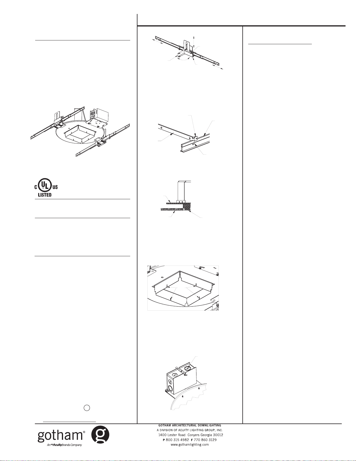
NEW INSTALLATION FOR SQ
Lay-in panel T-bar ceiling:
1. Cut ceiling opening slightly larger
than the outside diameter of the
mounting frame.
2. Position mounting frame through
opening in ceiling. Release clamping latch arms and adjust channel
bars to the correct spacing between T-bar as shown in Figure 1.
Secure channel bars to T-bar by
means of wire ties, screws or by
bending ends onto T-bar as shown
in Figure 2.
3. Once mounting frame has been
secured in structure, adjust the
mounting frame vertically to align
the bottom edge to either flush or
slightly above (1/8" max) the ceiling
line (Figure 3). Secure mounting
frame into position by closing the
clamping latch arm. The notch
located in the draw-down flange of
the housing can be used to assist
with alignment of multiple fixtures
(Figure 4).
4. If additional security is required, a
No. 8 sheet metal screw, wire tie or
wire (not supplied) may be used to
tie the latch arm to the mounting
frame as shown in Figure 1.
5. Remove knockouts on junction box to
feed power supply to fixture as
shown in Figure 5. Supply wire must
meet applicable electrical codes
and be rated for a minimum of 75oC.
Junction box is thru-wire rated for 8No. 12 AWG conductors (4 in-4 out).
6. Complete necessary wire connections. Snap the door onto the junction box.
7. To adjust trim after installation, see
“ Trim-Post Installation Adjustment.”
Figure 1
Channel
bar
Figure 2
Mounting
frame
Figure 3
Figure 4
Figure 5
Open
Ceiling
Clamping
latch arms
Closed
Bent tab
T-Bar
Wire tie
Flush or
slightly above
ceiling line
Sight
Notches
Remove
knockouts
as needed
CJ520004 Rev. B
1 of 2 6/10
©2007, 2010 Acuity Brands Lighting, Inc.
All Rights Reserved
Page 2
SQF, SQAZ and SQHZ Mounting Frames Installation Instructions
NEW INSTALLATION FOR SQ
Non-accessible ceiling (plaster, drywall,
etc.):
1.
For microflange (MFLG) installation,
an additional component (shipped
separately) is required to be installed
PRIOR TO drywall installation and ver tical alignment of this fixture.
2. Release clamping latch arms and
adjust channel bars to the correct
spacing between joists as shown in
Figure 1.
3.
Mounting Channel Bar-Flexible
Wiring Method
Bend ends of channel bars 90° and
adjustment at its lowest point on the
mounting frame. Make sure bottom
of the flange is flush with the bottom
of the joists. Secure mounting frame
into position by closing the clamping
latch arm. Channel bars will accom modate mount to joists with vertical
up to 24” O.C. joists. The notch located
in the draw-down flange of the housing
can be used to assist with alignment of
multiple fixtures.
Non-Flexible Wiring Method
If non-flexible wiring methods are used,
follow procedure for Flexible Wiring
Method, then lower mounting frame
equal to the thickness of the finished
ceiling or slightly above, as shown in
Figure 3. The notch located in the draw down flange of the housing can be used
to assist with alignment of multiple fix tures.
4. Remove knockouts on junction box to
feed power supply to fixture as shown
in Figure 5. Supply wire must meet ap plicable electrical codes and be rated
for a minimum of 90
thru-rated for 8-No. 12 AWG conductors
(4in- 4out).
o
C. Junction box is
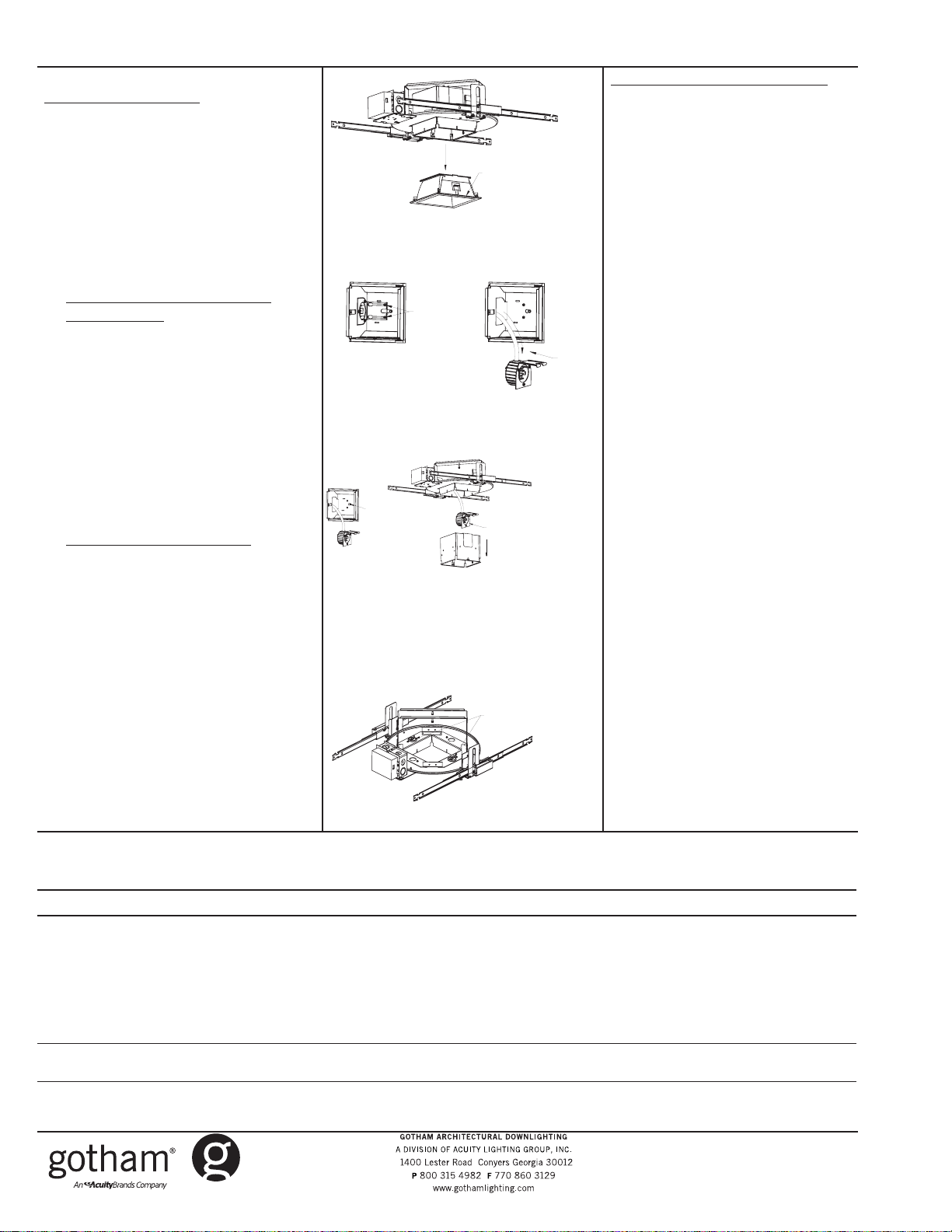
Figure 6
Figure 7
Figure 8
Figure 9
1. Loosen
main screw
and dis engage
from key
slots
1. Loosen
screws
in key
slots
Pull
down
Grip
edge of
flange
3. Remove socket cup
from upper reflector
2. Pull downupper
reflector
1. Loosen speed nuts
2. Adjust aperture
3. Retighten speed nuts
2. Pull
socket
cup
through
aper ture
Trim Post Installation Adjustment
In the event that the trim is in need of
alignment after installation, adjustment can be made to the housing.
1. Remove lower trim by gripping
edge of flange and pulling it out
of upper reflector and disengage
safety chain(Figure 6).
2. Remove lamp.
3. Loosen screws in key hole slots
of upper reflector, disengage from
slots and pull socket cup through
aperture (Figure 7).
4. Loosen screws in upper reflector,
disengage from keyhole slot and
remove upper reflector from hous ing (Figure 8).
5. To adjust housing for trim align ment, reach through aperture and
loosen two speed nuts. Adjust
housing as required and retighten
nuts (Figure 9).
6. Reinstall upper reflector, socket
cup, lamp and lower trim in reverse
order. If needed, refer to trim in stallation instructions.
ivynarofkcehC
motpmySesuaCelbissoPnoitcAevitcerroC
OTSLIAFPMAL
THGIL
TUOSEOGPMAL
GNITHGILRETFA
NOSELCYCPMAL
FFODNA
TRAHCGNITOOHSELBUORT
dezigrenetonerutxifehtgnideeftiucriC·
omrotiucricnirorregniriW·
pmalytluaF·
tuptuotsallabroeniL·
tuodenrubtsallaB·
wolooterutarepmettneibmA·
pmalytluaF· n
erutxifotesolcootsinoitalusnI·
hgihootegattawpmaL·
wolegatlovtuptuotsallaB·
.snoitcaevitcerrocdnasesuacelbissopfotsilgniwollofeht
noitcennocelud
.tcerroc
.enowenahtiw
ckcehC·
lovenilkcehC·
thgilotnwonksitahteno
.ytiunitnoctiucri
.pmalwenaetutitsbuS.thgilotgniliafylpmis
)"3tsaelta(eludomdnuoramorfnoitalusnievomeR·
.gnisuohnideificepsegattawpmalllatsnI·
nimelborpehtetacol,noitidnocdoognimeesyehtfI.eludomni-emarfropmalehtotegamadelbis
.dezigrenesitiucrictahterusneotesufrorekaerbtiucrickcehC·
erasnoitcennoctahterusneotxobecilpserutxifenimaxE·
ylbareferp,pmalrehtonaetutitsbusdnapmalytluafehtevomeR·
lanigiroehtecalper,sthgilpmalehtfI.
.egatlovtiucricnepokcehC.erutxiftaegatlovenilkcehC·
.snoitidnoclatnemnorivnegnitsixetsniagagnitartsallabkcehC·
ahtrehtarmotpmyssihttibihxelliwpmalayllanoisaccO·
.egatlovtiucricnepokcehC.erutxifehttaegat
CJ520004 Rev. B
2 of 2 6/10
©2007, 2010 Acuity Brands Lighting, Inc.
All Rights Reserved
 Loading...