

Page 1
INSTALLATION INSTRUCTIONS
SQP, SQDLW, SQPH,
SQDLWH, SQTH, SQDLWTH,
SQDLV, SQDMRH Mounting Frame
Upon receipt, thoroughly inspect for any freight
damage which should be brought to the attention of
the delivery carrier. Compare the catalog des cription
listed on the packing slip with the label on the carto n
to ensure you have received the correct
merchandise.
IMPORTANT SAFETY INFORMATION
For Your Protection, Read Carefully
WARNING: Risk of fire. Do not install insulation
within 3 inches of fixture sides or wiring compartment,
nor above the fixture in such a manner as to entrap
heat.
This product must be installed by a person familiar
with the construction and operation of the product
and the hazards involved, in accordance with the
applicable installation code.
1. Electric current can cause painful shock or
serious injury unless handled properly. For you
safety, always remember the following:
•Turn off the supply power.
•Ground the fixture to avoid potential electrical
shocks.
•Do not handle an energized fixture or ener gize
any fixture with wet hands, when standing on a
wet or damp surface, or in water.
2. Specific safety information concerning
lamps:
•Match wattage of fixture and lamp exactly.
•Do not remove or insert lamp when power is
on.
•Do not scratch glass or subjec t lamp to undue
pressure as either may cause lamp breakage.
•Protect operating lamp from sources of
moisture.
• If lamp is marked it contains mercury.
Follow disposal laws. See:
www.lamprecycle.org
.
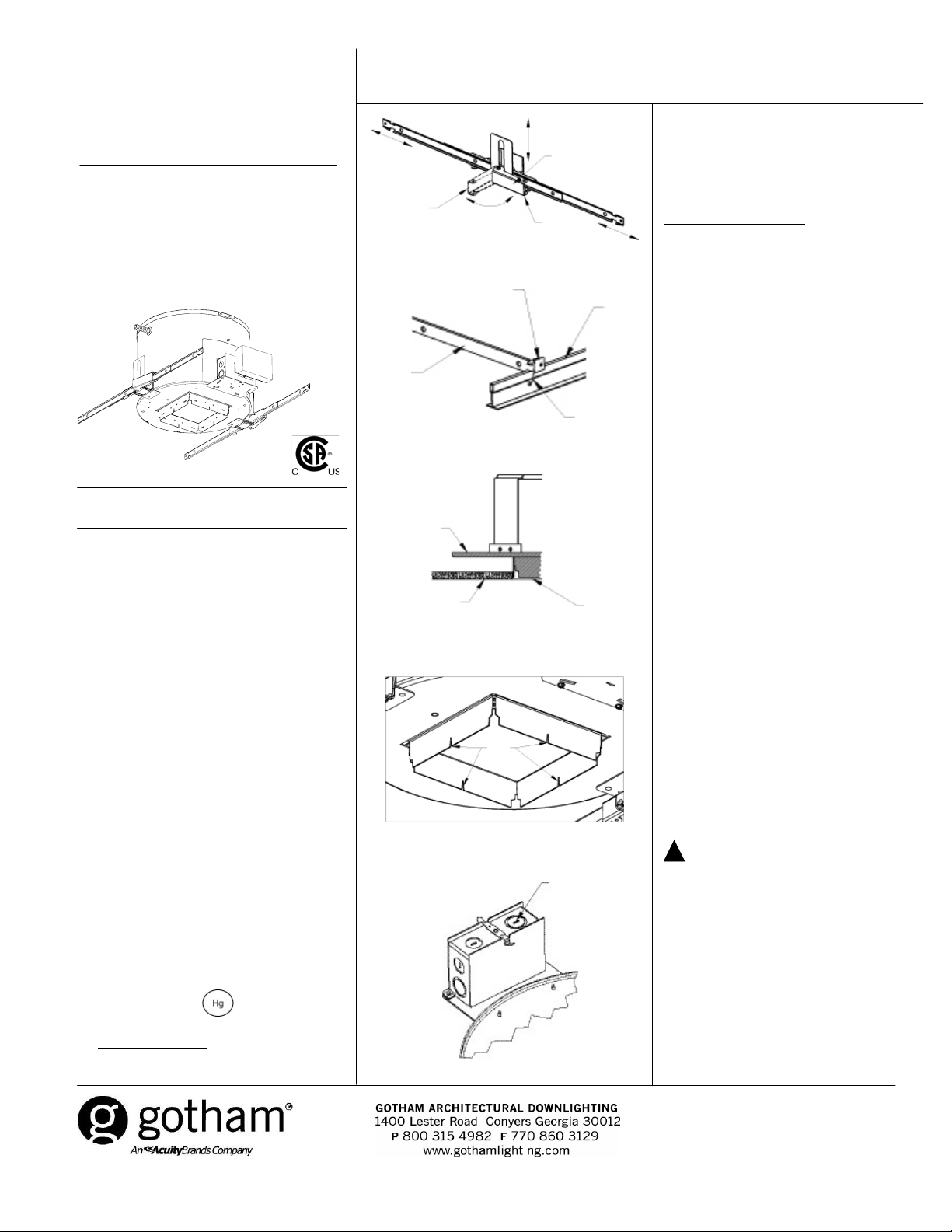
Open
Figure 1
Channel
bar
Figure 2
Mounting
Figure 3
Figure 4
Figure 5
SAVE THESE INSTRUCTIONS
NEW INSTALLATION FOR SQ SERIES
IMPORTANT! For wallwash housing
orientation installation details see
page 2.
Lay-in panel T-bar ceiling:
1. Cut ceiling opening slightly larg er than the
outside opening of the mounting frame.
2. Position mounting frame through openin g in
ceiling. Release clamping latch arms and
adjust channel bars to the correct spacing
between T-bar (see Figure 1). Secure channel
bars to T-bar by means of wire ties, screws or
by bending ends onto T-bar (see Figure 2).
3. Once mounting frame has been secured in
structure, adjust the mounting frame vertic ally
to align the bottom edge to either flush or
slightly above (1/8" max) the ceiling line (see
Figure 3). Secure mounting frame into position
by closing the clamping latc h arm. The notch
located in the draw-down flange of the ho us ing
can be used to assist with alignment of
multiple fixtures (see Figure 4).
4. If additional security is required, a No. 8
sheet metal screw, wire tie or wire (not
supplied) may be used to tie the latc h arm to
the mounting frame (see Figure 1).
5. Remove knockouts on junction box to feed
power supply to fixture (see Figure 5). Supp ly
wire must meet applicable electrical co des an d
be rated for a minimum of 90°C. Junctio n bo x
is thru-wire rated for 8-No. 12 AWG
conductors (4 in-4 out).
6. Complete necessary wire connections.
Snap the door onto the junction box.
7. To adjust housing alignment after
installation, see “Post Installation
Adjustment.”
!
CAUTION! For T4/T6 and low voltage
MR16 downlights, lens must be in place in
front of lamp before fixture is energized.
frame
Ceiling
Clamping
latch arms
Closed
Bent tab
T-Bar
Wire tie
Flush or
slightly
above
ceiling line
Sight
Notches
Remove
knockouts
as needed
CJ5200903 Rev. B
6/10 1 of 2
©2009, 2010 Acuity Brands Lighting, Inc.
All Rights Reserved.
Page 2
SQP, SQDLW, SQPH, SQDLWH, SQTH, SQDLWTH, SQDLV, SQDMRH Mounting Frame Installation Instructions
NEW INSTALLATION FOR SQ SERIES
Non-accessible ceiling
1. For microflange (MFLG) installation, an
additional component (shipped separately) is
required to be installed PRIOR TO drywall
installation and vertical alignment of this
fixture.
2. Release clamping latch arms and adjust c hannel
bars to the correct spacing between joists (see
Figure 1).
Mounting Channel Bar-Flexible Wiring Method
3. Bend ends of channel bars 90° and adjustment at
its lowest point on the mounting frame. Mak e sure
bottom of the flange is flush with the bottom of the
joists. Secure mounting frame into position by
closing the clamping latch arm. Channel bars will
accommodate up to 24” O.C. joists. The notch
located in the draw-dow n flange of the housing c an
be used to assist with alignment of multiple fixtures.
Non-Flexible Wiring Method
If non-flexible wiring methods are used, follow
procedure for Flexible Wiring Method, then lower
mounting frame equal to the thickness of the
finished ceiling or slightly abov e, (1/8” max. - se e
Figure 3). The notch located in the draw-down
flange of the housing can be used to assist with
alignment of multiple fixtures.
4. Remove knockouts on junction box to feed power
supply to fixture (see Figure 5). Supply wire must
meet applicable electrical code s and be rated for a
minimum of 90°C. Junction box is thru- wire rated
for 8-No. 12 AWG conductors(4in-4out).
(plaster, drywall, etc.):
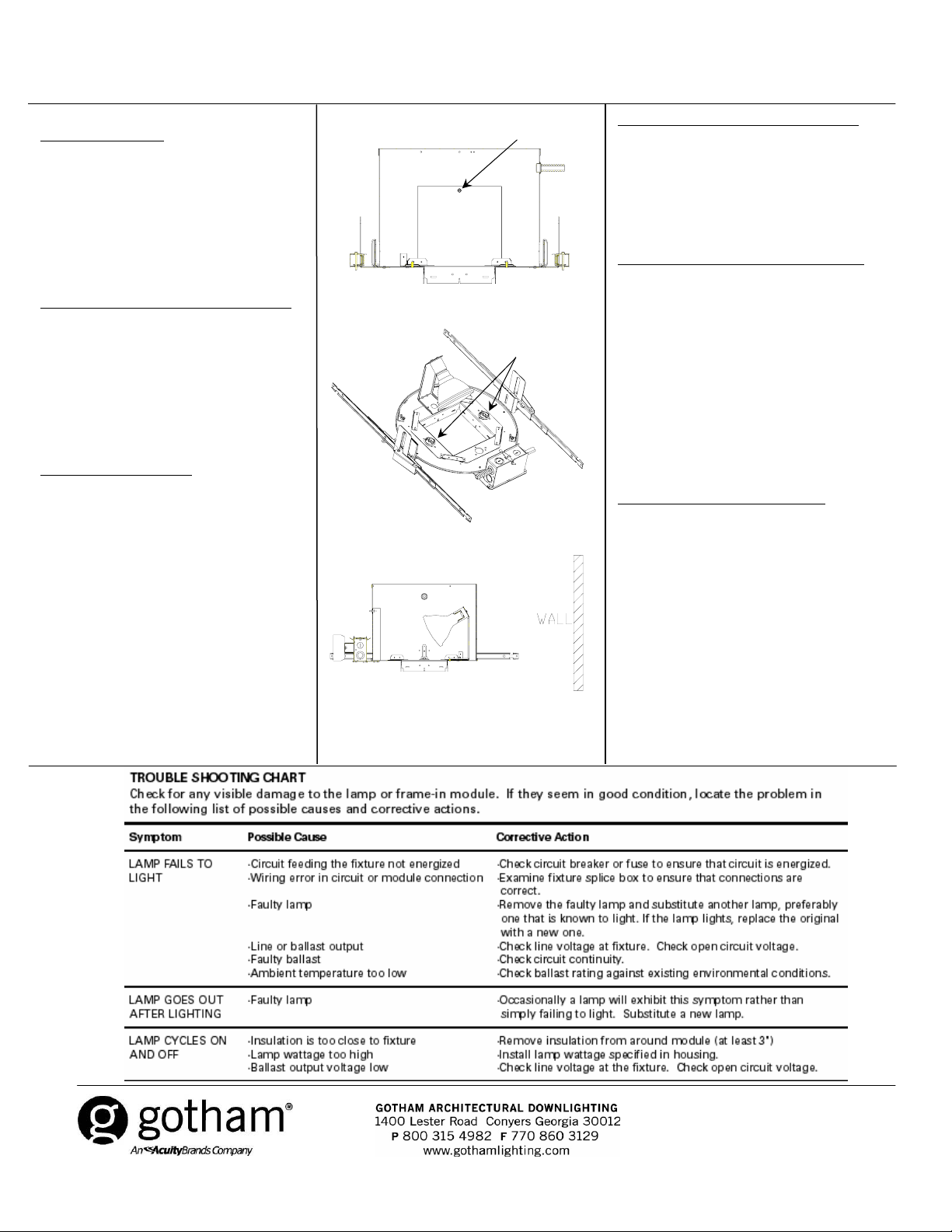
Figure 6
Figure 7
Figure 8
Thumb screw
Speed nuts
ACCESSING JUNCTION BOX FROM BELOW
To gain access to junction box from below ceiling.
1. Remove trim.
2. Remove lamp. (PAR lamps only)
3. Loosen thumb screw to remove door from
housing and set aside. (see Figure 6).
POST INSTALLATION HOUSING ALIGNMENT
In the event that the trim is in need of alignment
after installation, adjustments can be made to the
housing.
1. Remove trim by gripping edge of flange and
pulling it out of housing.
2. To adjust housing for trim alignment, reach
through aperture and loosen two speed nuts (see
Figure 7). Adjust housing as required and retighten
nuts.
3. Reinstall trim. If needed, refer to trim installation
instructions.
WALLWASH HOUSING ORIENTATION
WALLWASH HOUSING ONLY:
(SQDLW, SQDLWH, SQDLWTH, SQDLV
wallwash and SQDMRH wallwash)
1. Install wallwash housing so that lamp is aimed
away from the wall (see Figure 8). If housing is
installed incorrectly with lamp aimed towards wall,
reach through aperture and r emove two (2) speed
nuts. Rotate socket mounting bracket so that it is
aimed away from wall and reinstall speed nuts.
CJ5200903 Rev. B
6/10 2 of 2
©2009, 2010 Acuity Brands Lighting, Inc. All
Rights Reserved.
 Loading...