

Page 1
INSTALLATION INSTRUCTIONS
High Elevations
®
Performance Decorative Pendant
Elevations 10" and 14"
Upon receipt, thoroughly inspect for any
freight damage which should be brought to
the attention of the delivery carrier. Compare
the catalog description listed on the packing
slip with the label on the carton to ensure you
have received the correct merchandise.
IMPORTANT SAFETY INFORMATION
For Your Protection, Read Carefully
1. Electric current can cause painful shock
or serious injury unless handled properly. For your safety, always remember
the following:
• Turn off the power supply.
• Ground the fixture to avoid potential
electrical shocks.
• Do not handle an energized fixture or
energize any fixture with wet hands,
when standing on a wet or damp surface, or in water.
• Double check all electrical connections
to be sure they are tight and correct.
2. Specific safety information concerning
lamps:
• Match wattage of fixture and lamp
exactly.
• Do not remove or insert lamp when
power is on.
• Do not scratch glass or subject lamp to
undue pressure as either may cause
lamp breakage.
• Protect operating lamp from sources
of moisture.
SA VE THESE INSTRUCTIONS
STEM MOUNT INSTRUCTIONS (Stem mount kits shipped separately)
1. Determine the length of wires required to fit through the stem and splice them to
the incoming power. There should be at least 6" of wires exiting the end of the
stem(s). WARNING!!! RISK OF FIRE!!! WIRE USED TO MAKE THE WIRING
CONNECTION INSIDE THE FIXTURE MUST BE RATED FOR 150°C.
2. Install stem assembly, see stem instruction sheet.
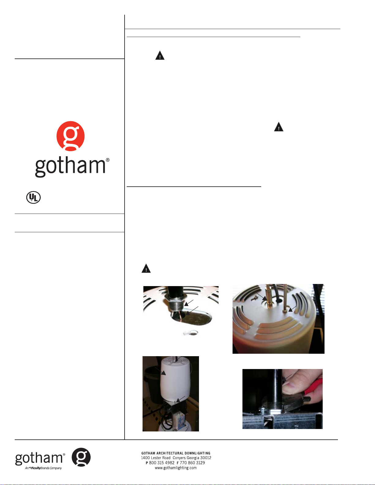
3. Thread wires through threaded opening in top of ballast housing, then insert end
of stem into threaded opening (See Figure 1). Screw ballast housing onto stem
until it comes in contact with the locknut on the end of the stem. Ensure ballast
housing is securely attached before proceeding.
4. Loosen two screws holding the painted cover on the ballast housing and
disengage them from the keyhole slots (See Figure 2). Lift the cover and place it
behind a screw located on the ballast housing bracket (See Figure 3).
5. Tighten locknut located on end of stem (See Figure 4). WARNING!!! RISK OF
INJURY OR DEATH!!! IF LOCKNUT IS NOT TIGHTENED FIXTURE MAY FALL!!
6. Make required wire connections and tuck all wires inside ballast housing
bracket.
7. Reinstall painted ballast housing cover and tighten screws.
8. For 10" reflector installation, proceed to instruction sheet located in trim box. For
14" products, proceed to “14” Lower Pendant Instructions” below.
14" LOWER PENDANT INSTALLATION INSTRUCTIONS
1. Remove all cardboard filler.
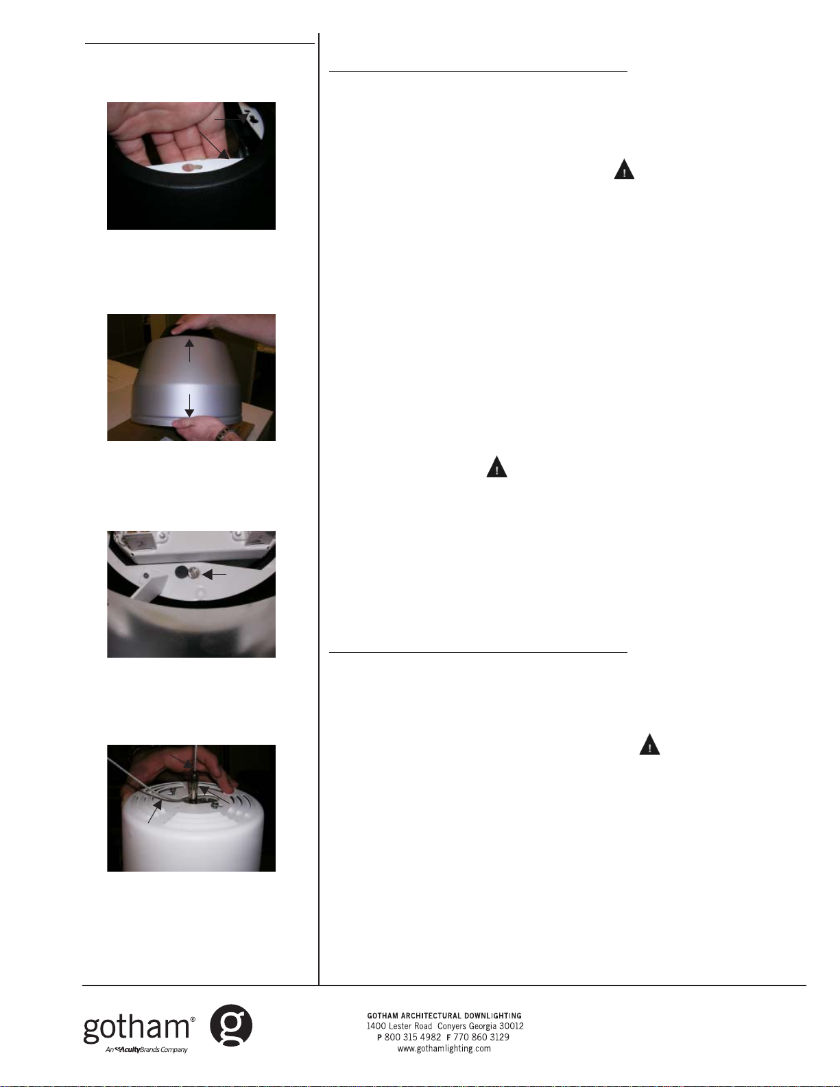
2. Remove lower pendant assembly from carton and place it on a clean surface. To
remove assembly, grip the white painted bracket (See Figure 5). CAUTION!! DECORA-
TIVE GLASS IS NOT ATTACHED TO ASSEMBLY, EXERCISE CAUTION WHILE HANDLING.
3. Pick up the lower pendant assembly with both hands, ensuring that the reflector
does not slip out of the assembly (See Figure 6).
4. Install the lower pendant assembly by engaging the 4 screws located on the
bottom of the ballast housing in the keyhole slots of the assembly bracket. For
HID units without decorative glass, the keyhole slots are located behind the
holes in the upper portion of the reflector. Tighten screws until snug (See Figure
7). WARNING!!! RISK OF INJURY OR DEATH!!! IF SCREWS ARE NOT TIGHTENED SECURELY, LOWER PENDANT ASSEMBLY MAY FALL!!
5. Install lamp(s) and energize product.
Cable
Glider
Screw
Figure 2
Stem
Locknut
Ballast housing
Figure 4
Painted
cover
Ballast
housing
Screw
Figure 3
Stem
Threaded
opening
Figure 1
Part No. CJ520086
©2008 Gotham Rev A. 5/08
High Elevations
Page 1 of 3
®
Page 2
Fixture connections and hanging instructions
White
painted
bracket
Figure 5
Proper
handling of
14" reflector
Figure 6
Keyhole
slots
High Elevations® 10" ACC
AIRCRAFT CABLE AND CORD MOUNT INSTRUCTIONS
1. Securely attach the junction box mounting plate to 4" j-box.
2. On the ground, insert end of aircraft cable into cable glider located on top of
ballast housing. Be sure to leave at least 4" of cable exiting the glider and
ensure that the cable is securely attached (See Figure 8).
3. Attach assembly support chain to the hole in canopy allowing fixture to hang and
make required wire connections (See Figure 9). WARNING!!! RISK OF INJURY
OR DEATH!!! IF AIRCRAFT CABLE IS NOT SECURELY ATTACHED TO PENDANT IT
MAY FALL!!
4. Remove the assembly support chain while holding the fixture, tuck all wires inside
the canopy and attach the canopy to the mounting plate. Securely tighten the
three screws.
5. Determine required length of cable and adjust as required. (10 FEET OF CABLE
PROVIDED). It is recommended that the cut end of cable be soldered or glued to
prevent it from fraying.
6. Insert end of the power cord at least 8 inches into the hole located next to the
aircraft cable glider (See Figure 8).
7. Loosen two screws holding the painted cover on the ballast housing and
disengage them from the keyhole slots (See Figure 2). Lift the cover and place it
behind a screw located on the ballast housing bracket (See Figure 3).
8. Determine required length of cord and make necessary cuts (10 FEET OF CORD
PROVIDED).
9. Make required wire connections and tuck all wires inside of ballast housing
bracket.
10. Install power cord strain relief on cord jacket just below the hole in the ballast
bracket (See Figure 10). WARNING!!! RISK OF INJURY OR DEATH!!! CABLE
SUPPORTS WEIGHT OF FIXTURE. CORD CANNOT BE USED TO SUPPORT WEIGHT.
IF AIRCRAFT CABLE IS NOT SECURLY ATTACHED TO PENDANT IT MAY FALL!!
11. Reinstall ballast housing cover and tighten screws.
12. Install cord keeper wire ties as required.
13. Install trim (shipped separately).
14. Install lamp(s) and energize product.
Aircraft
cable
Cable should
exit glider at
least 4"
Cable
glider
Figure 7
Figure 8
High Elevations® 14" ACC
AIRCRAFT CABLE AND CORD MOUNT INSTRUCTIONS
1. Securely attach junction box mounting plate to 4" j-box.
2. On the ground, insert end of aircraft cable into cable glider located on top of
ballast housing. Be sure to leave at least 4" of cable exiting the glider (See
Figure 8).
3. Attach assembly support chain to the hole in canopy, allowing fixture to hang
and make required wire connections (See Figure 9). WARNING!!! RISK OF
INJURY OR DEATH!!! IF AIRCRAFT CABLE IS NOT SECURELY ATTACHED TO
PENDANT IT MAY FALL!!
4. Remove the assembly support chain while holding the fixture, tuck all wires inside
the canopy and attach the canopy to the mounting plate. Securely tighten the
three screws.
5. Remove all cardboard filler from carton containing the lower pendant assembly.
6. Remove lower pendant assembly from carton and place it on a clean surface. To
remove assembly, grip the white painted bracket (See Figure 5). CAUTION!!
DECORATIVE GLASS IS NOT ATTACHED TO ASSEMBLY, EXERCISE CAUTION WHILE
HANDLING.
7. Pick up the lower pendant assembly with both hands, ensuring that the reflector does not slip out of the assembly (See Figure 6).
Part No. CJ520086
©2008 Gotham Rev A. 5/08
High Elevations
Page 2 of 3
®
Page 3

Fixture connections and hanging instructions
Mount-
ing plate
Support
chain
Canopy
Figure 9
Power cord
strain relief
Figure 10
8. Install the lower pendant assembly by engaging the 4 screws located on the
bottom of the ballast housing in the keyhole slots of the white painted bracket.
For HID units without decorative glass, the keyhole slots are located behind the
holes in the upper portion of the reflector. Tighten screws until snug (See
Figure 7). WARNING!!! RISK OF INJURY OR DEATH!!! IF SCREWS ARE NOT
TIGHTENED SECURELY, LOWER PENDANT ASSEMBLY MAY FALL!!
9. Determine required length of cable and adjust as required. (10 FEET OF CABLE
PROVIDED). It is recommended that the cut end of cable be soldered or glued to
prevent it from fraying.
10. Insert end of the power cord at least 8 inches into the hole located next to the
aircraft cable glider (See Figure 8).
11. Loosen two screws holding the painted cover on the ballast housing, disengaging them from the keyhole slots (See Figure 2). Lift the cover and place it behind
a screw located on the ballast housing bracket (See Figure 3).
12. Determine required length of cord and make necessary cuts (10 FEET OF CORD
PROVIDED).
13. Make required wire connections and tuck all wires inside ballast housing
bracket.
14. Install power cord strain relief on cord jacket just below the hole in the ballast
bracket (See Figure 10). WARNING!!! RISK OF INJURY OR DEATH!!! CABLE
SUPPORTS WEIGHT OF FIXTURE. CORD CANNOT BE USED TO SUPPORT WEIGHT.
IF AIRCRAFT CABLE IS NOT SECURELY ATTACHED TO PENDANT IT MAY FALL!!
15. Reinstall ballast housing cover and tighten screws.
16. Install cord keeper wire ties as required.
17. Install lamp(s) and energize product.
ivynarofkcehC
TRAHCGNITOOHSELBUORT
motpmySesuaCelbissoPnoitcAevitcerroC
THGIL
DNA
OTSLIAFPMAL
pmalytluaF·
tsallabytluaF·
TUOSEOGPMAL
GNITHGILRETFA
NOSELCYCPMAL
FFO
pmalytluaF· naht
omrotiucricnirorregniriW·
tuptuotsallabroeniL·
wolooterutarepmettneibmA·
erutxifotesolcootsinoitalusnI·
hgihootegattawpmaL·
wolegatlovtuptuotsallaB·
.snoitcaevitcerrocdnasesuacelbissopfotsilgniwollofeht
nimelborpehtetacol,noitidnocdoognimeesyehtfI.eludomni-emarfropmalehtotegamadelbis
.dezig
dezigrenetonerutxifehtgnideeftiucriC·
noitcennocelud
.tcerroc
ilotnwonksitahteno
.enowenahtiw
ehC·
enilkcehC·
.ytiunitnoctiucrickc
.pmalwenaetutitsbuS.thgilotgniliafylpmis
rfnoitalusnievomeR·
.gnisuohnideificepsegattawpmalllatsnI·
renesitiucrictahterusneotesufrorekaerbtiucrickcehC·
erasnoitcennoctahterusneotxobecilpserutxifenimaxE·
ylbareferp,pmalrehtonaetutitsbusdnapmalytluafehtevomeR·
lanigiroehtecalper,sthgilpmalehtfI.thg
.egatlovtiucricnepokcehC.erutxiftaegatlovenilkcehC·
.snoitidnoclatnemnorivnegnitsixetsniagagnitartsallabkcehC·
rehtarmotpmyssihttibihxelliwpmalayllanoisaccO·
)"3tsaelta(eludomdnuoramo
.egatlovtiucricnepokcehC.erutxifehttaegatlov
Part No. CJ520086
©2008 Gotham Rev A. 5/08
High Elevations
Page 3 of 3
®
 Loading...