

Page 1
INSTALLATION INSTRUCTIONS
HEQ
SAVE THESE INSTRUCTIONS
Upon receipt, thoroughly inspect for any freight
damage which should be brought to the attention of
the delivery carrier. Compare the catalog
description listed on the packing s lip with the label
on the carton to ensure you have received the
correct merchandise.
IMPORTANT SAFETY INFORMATION
For Your Protection, Read Carefully
WARNING - Turn of all power prior to beginning
any installation or maintenance of this fixture.
RISK OF FIRE. THIS FIXTURE IS NON I/C
RATED, NOT FOR USE WITH INSULATION.
Do not install insulation within 3 inches of fixture
sides or wiring compartment, nor above the fix ture
in such a manner as to entrap heat.
WARNING: DO NOT ENERGIZE FIXTURES
WITHOUT FINISH TRIM IN PLACE. PROTECTIVE
GLASS SHIELD MUST BE USED WITH THIS
FIXTURE AT ALL TIMES.
FIXTURES REQUIRE 3 inches of overhead
clearance in non-above ceiling access
applications for branch circuit inspection.
PRIOR TO INSTALLATION
Read and familiarize yourself with the
nomenclature and instructions before starting
installation.
Turn off electricity at the breaker panel or
fuse box and follow Nationa l Electrical C ode
regulations and applicable local building
codes.
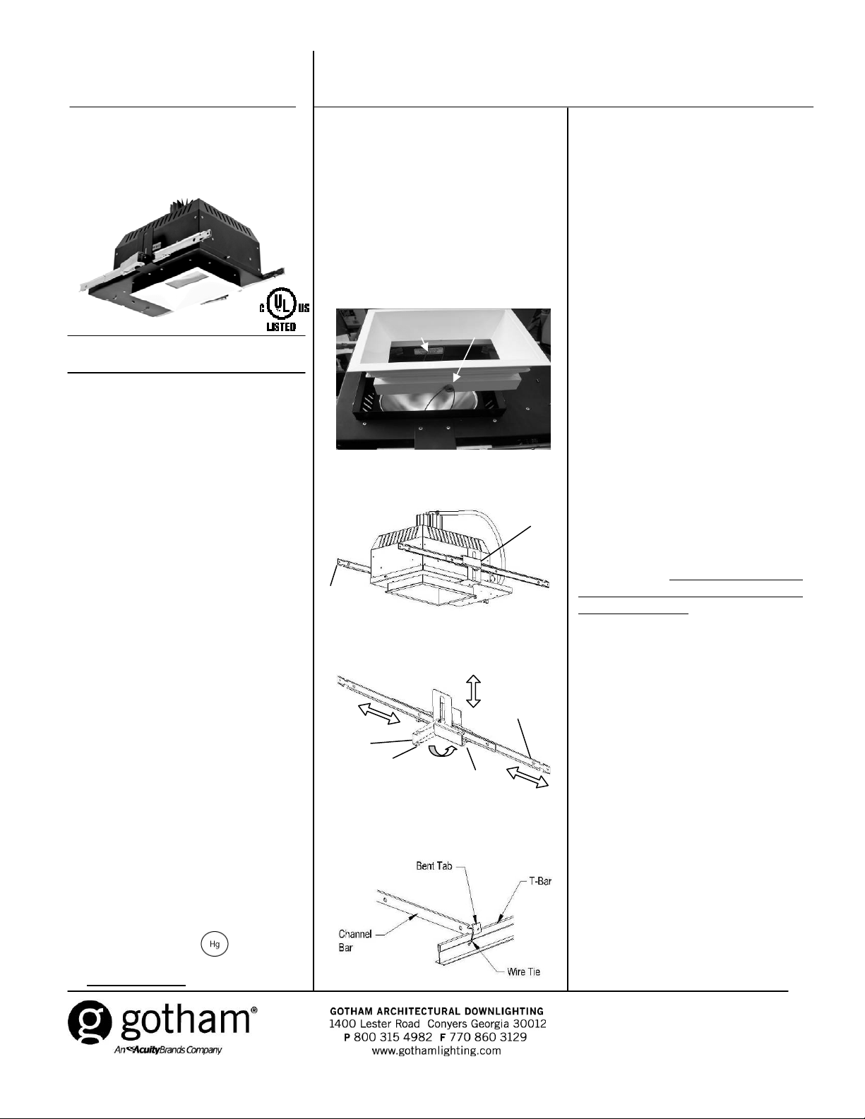
Torsion springs
Figure 1
B
A
Figure 2
HOUSING INSTALLATION FOR T-BAR,
WOOD OR STEEL JOIST
CONSTRUCTION
Always mount securely to structural
members. This fixture will accommodate 1”
thick ceilings.
1. Remove trim by grabbing flange and
pulling up, compress both tor sion springs to
release trim. (See Figure 1)
2. Bend ends of bar hangers (See Figure
2A) to a position appropriate for attach ment
to joist if necessary (wood joist, nail or
screw tabs).
3. Release cam lever (See Figures 2B and
3A) and center bar hangers (Figure 3B) in
the vertical slot to approximate width
needed. Engage cam lever to secure,
repeat on opposite side.
4. Position fixture so that the HEAD OF
BED label is toward the head of the hospital
bed and then install fixture between joists o r
on T-bar so the bottom of the drop down
flange is flush or slightly above the bottom
of the finished ceiling.
1. Electric current can cause painful shock or
serious injury unless handled properly. For
you safety, always remember the following:
•Turn off the supply power.
•Ground the fixture to avoid potential electrical
shocks.
•Do not handle an energized fixture or
energize any fixture with wet hands, when
standing on a wet or damp surface, or in
water.
2. Specific safety information concerning
lamps:
•Match wattage of fixture and lamp exactly.
•Do not remove or insert lamp when power is
on.
•Do not scratch glass or subject lamp to
undue pressure as either may cause lamp
breakage.
•Protect operating lamp from sources of
moisture.
• If lamp is marked it contains
mercury. Follow disposal laws. See:
www.lamprecycle.org
.
A
Figure 3
Open
Closed
B
Figure 4
5. Secure bar hangers/housing assembly
onto joist/T-bar material. On wood/steel
joist, use nails, screws or bolts; for T-bar,
use wire or wire ties and bend nailing tab
(See Figure 4).
6. Adjust housing to desired position by
releasing cam lever (one on each side ) and
making horizontal and/or vertical
adjustments as necessary. Secure cam
levers.
(continued on back)
CJ520717 Rev. A
3/2009
1 of 2
Page 2
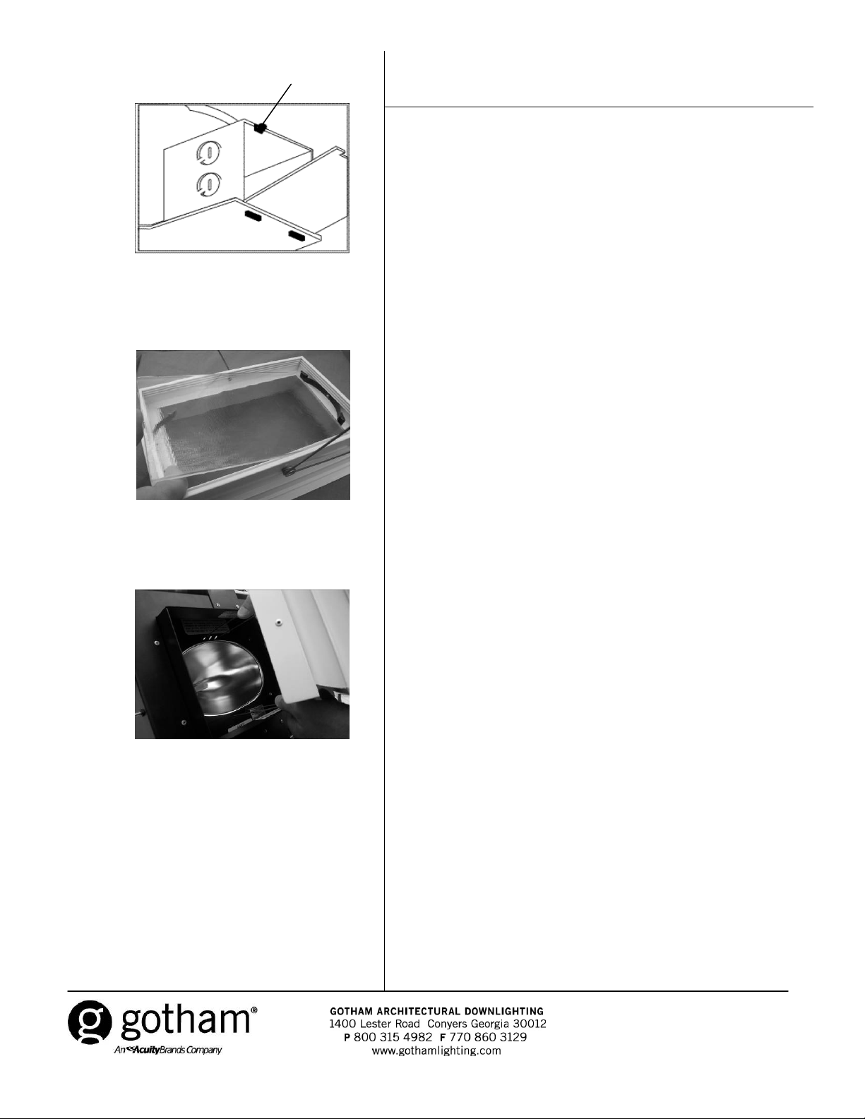
Figure 5
A
SAVE THESE INSTRUCTIONS
7. Feed power supply to J-box. (See Figure 5)
- J-box is approved for through wiring with eight No. 12 AWG
conductors (4 in/4 out) rated 90°C or higher.
- Remove J-box cover by releasing spring clip (See Figure 5A) and
B
allowing cover to hinge open (See Figure 5B).
- Select desired knockout, remove and install appropriate connector.
- Install power conductors in accordance with all local and/or National
Electric Codes and ordinances ( consu lt your lo cal build ing author it y fo r
specific requirements).
- Make connections using code approved materials/methods.
-Reinstall J-box cover (See Figure 5B).
8. Install ceiling material , cut hole out for drop down f lange (7” x 9 ¾ ”
ceiling opening), being careful not to cut the hole too large.
9. Insert lens in trim by sliding into spring brackets. (See Figure 6).
10. Install lamp (this fixture requires a coa ted (frosted) T-4 mini-can
base lamp). Consult label on inside of drop down fla nge of housing fo r
specific wattages appropriate for your fixture. Fixtures are wattage
specific. Be sure to read and follow all of the lamp manufacturers
directions and recommendati o n s.
Figure 6
Figure 7
11. Place torsion springs into slot s in mounting frame and push trim
into place. (See Figure 7)
12. To access junction box, slightly loosen two thumb screws along
lower inside edge of housing. Move upper housing to the side to
access junction box. Replace housing before energizing.
WARNING: DO NOT ENERGIZE FIXTURES WITHOUT FINISH TRIM
IN PLACE. PROTECTIVE GLASS SHIELD MUST BE USED WITH
THIS FIXTURE AT ALL TIMES.
CJ520717 Rev. A
3/2009
2 of 2
 Loading...