

Page 1
INSTALLATION INSTRUCTIONS
Ellipsodial Pendant
GQP10, GQP10ACC & GQP10WM
Upon receipt, thoroughly inspect for any
freight damage which should be brought to
the attention of the delivery carrier. Compare
the catalog description listed on the packing
slip with the label on the carton to ensure
that you have received the correct merchandise.
®
IMPORTANT SAFETY INFORMATION
For Your Protection, Read Carefully
1. Electric current can cause painful shock
or serious injury unless handled properly.
For your safety, always remember the following:
· Turn off the power supply.
· Ground the fixture to avoid potential
electrical shocks.
· Do not handle an energized fixture or
energize any fixture with wet hands,
when standing on a wet or damp surface, or in water.
· Double check all electrical connections
to be sure they are tight and correct.
SAVE THESE INSTRUCTIONS
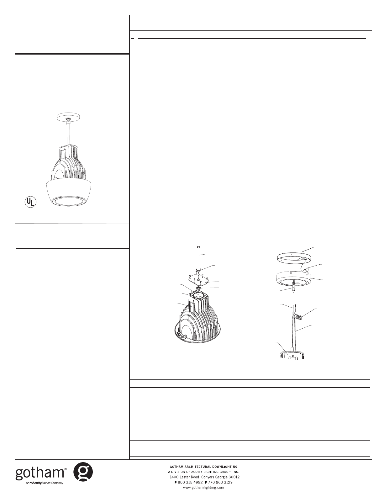
I. GQP STEM MOUNT INSTRUCTIONS (Stem mount kits shipped separately) (see Figure 1)
1. Remove screws from top cover plate and remove from upper housing.
2. Screw locknut onto end of stem until snug.
3. Insert end of stem into hole in top cover plate and secure with second locknut.
4. Pull wires from housing through stem. Fixture ships with 3’ of 1050C wire. Longer wire
lengths must be supplied by others. If longer lengths are required, splice leads in compartment located in the top of upper housing under the top cover plate. Be sure splices are
made above insulated discs. Wire and splices must be rated 105°C minimum.
5. Reattach top cover plate to upper housing.
6. Connect leads in 4" junction box and install canopy (follow instructions provided with stem
kit).
7. Install lamp.
8. Install trim (shipped separately).
II. GQP ACC - AIRCRAFT CABLE AND CORD MOUNT INSTRUCTIONS (see Figure 2)
1. Fasten canopy mounting pan to 4” junction box.
2. On the ground, determine required length of cord and cable and make necessary cuts (10
FEET). OF CORD AND CABLE PROVIDED). It is recommended that the cut end of cable be
soldered or glued to prevent it from fraying.
3. Attach strain relief bushing to cord and install in canopy, making sure widest flat surface of
the bushing will face floor.
4. Insert cable into end of cable glider, making sure the end of cable protrudes at least 1” from
the cable exit on side of glider. WARNING: CABLE SUPPORTS WEIGHT OF FIXTURE. CORD
CANNOT BE USED TO SUPPORT WEIGHT.
5. Hang fixture assembly from “S” hook safety chain attached to canopy mounting pan.
6. Make wire connections.
7. Secure fixture canopy to canopy mounting pan making sure all screws are tightly secured.
8. For cord management fasten wire ties along cable and cord and snip off the ends.
9. Install lamp.
10. Install trim (shipped separately).
Canopy
Mounting
Pan
"S" Hook/Mounting
Chain
Canopy
Strain Relief
Bushing
Cord
Figure 2
Splice Compartment
Insulated Disc
Upper Housing
Figure 1
Stem
Locknut
Top Plate
Locknut
Cable Glider
Cable
Fixture
2. Specific safety information concerning
lamps:
· Match wattage of fixture and lamp ex-
actly.
· Do not remove or insert lamp when power
is on.
· Do not scratch glass or subject lamp to
undue pressure as either may cause
lamp breakage.
· Protect operating lamp from sources
of moisture.
ivynarofkcehC
motpmySesuaCelbissoPnoitcAevitcerroC
OTSLIAFPMAL
THGIL
TUOSEOGPMAL
GNITHGILRETFA
DNA
NOSELCYCPMAL
FFO
TRAHCGNITOOHSELBUORT
omrotiucricnirorregniriW·
pmalytluaF·
tuptuotsallabroeniL·
tsallabytluaF·
pmalytluaF· naht
wolooterutarepmettneibmA·
erutxifotesolcootsinoitalusnI·
hgihootegattawpmaL·
wolegatlovtuptuotsallaB·
.snoitcaevitcerrocdnasesuacelbissopfotsilgniwollofeht
dezigrenetonerutxifehtgnideeftiucriC·
noitcennocelud
.tcerroc
ilotnwonksitahteno
.enowenahtiw
ehC·
enilkcehC·
.ytiunitnoctiucrickc
.pmalwenaetutitsbuS.thgilotgniliafylpmis
rfnoitalusnievomeR·
.gnisuohnideificepsegattawpmalllatsnI·
nimelborpehtetacol,noitidnocdoognimeesyehtfI.eludomni-emarfropmalehtotegamadelbis
.dezig
renesitiucrictahterusneotesufrorekaerbtiucrickcehC·
erasnoitcennoctahterusneotxobecilpserutxifenimaxE·
ylbareferp,pmalrehtonaetutitsbusdnapmalytluafehtevomeR·
lanigiroehtecalper,sthgilpmalehtfI.thg
.egatlovtiucricnepokcehC.erutxiftaegatlovenilkcehC·
.snoitidnoclatnemnorivnegnitsixetsniagagnitartsallabkcehC·
rehtarmotpmyssihttibihxelliwpmalayllanoisaccO·
)"3tsaelta(eludomdnuoramo
.egatlovtiucricnepokcehC.erutxifehttaegatlov
CJ52086 Rev. B
2/11 1 of 2
©2006, 2011 Acuity Brands Lighting, Inc.
All Rights Reserved.
Page 2
Upper
Housing
1/4 Turn
Fastner
Adjustment
Bolt
1/4 Turn
Fastner
Lower
Housing
Adjustment
Bolt
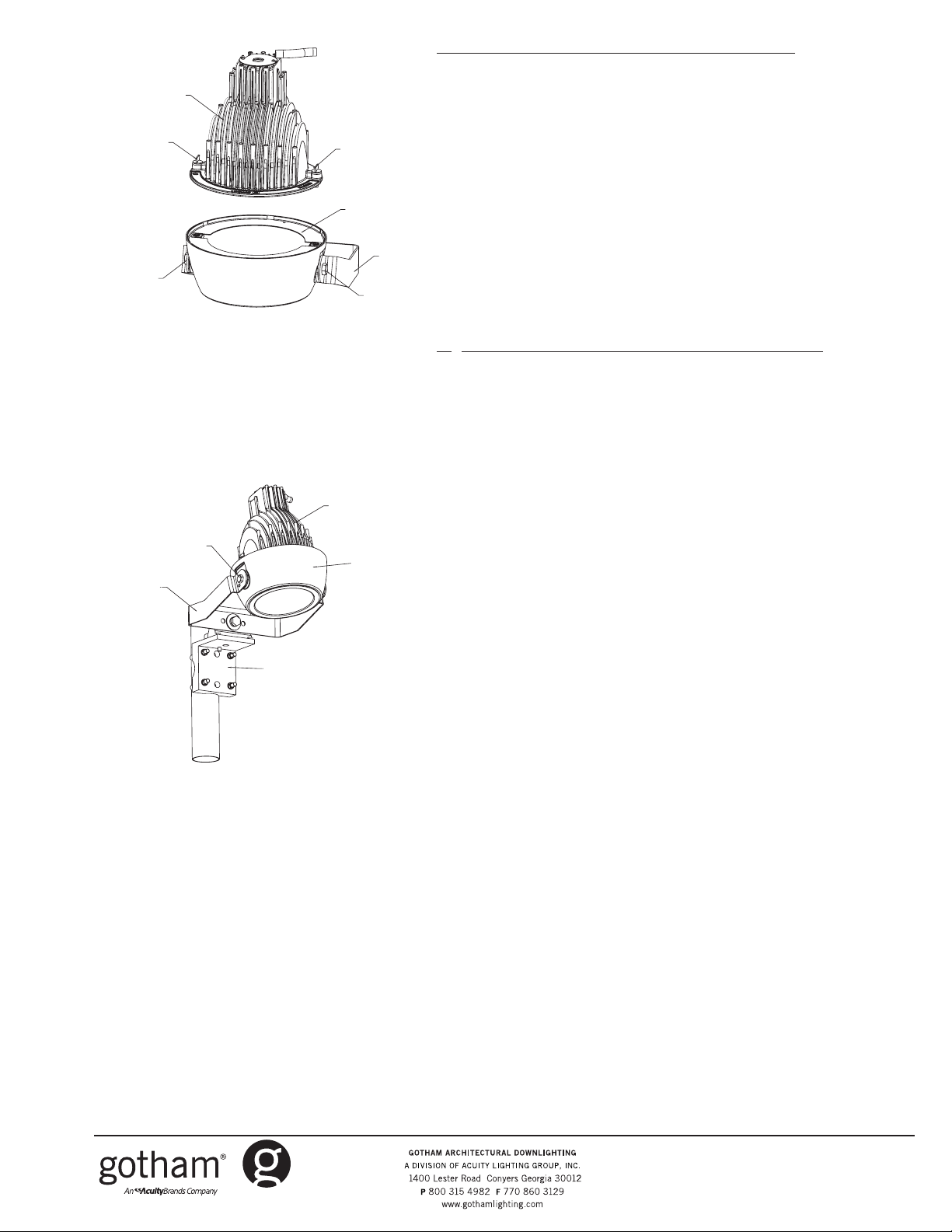
III. GQP WM - WALL MOUNT INSTRUCTIONS (see Figure 3)
1. Remove upper housing from lower housing by loosening ¼ turn
fasteners.
2. Fasten yoke with lower housing attached to wall (fasteners provided by
others).
3. Reattach upper housing.
4. Attach romex to junction box and make wire connections.
5. Install lamp
6. Install trim (shipped separately).
7. After fixture is securely installed, loosen bolts located on either side of
lower housing and adjust fixture to desired position. Retighten bolts.
Yoke
Figure 3
Figure 4
Adjustment
Bolt (2)
Yoke
FPMB
Mounting
Bracket
Upper
Housing
Lower
Housing
IV. GQP WM - CATWALK MOUNT INSTRUCTIONS (see Figure 4)
1. Mount FPMB mounting bracket to structure. (Follow instructions provided
with FPMB mounting bracket-sold separately).
2. Attach fixture to FPMB mounting bracket through center hole in yoke.
3. Attach romex to junction box and make wire connections.
4. Install lamp.
5. Install trim (shipped separately).
6. After fixture is securely installed, loosen bolts located on either side of
lower housing and adjust fixture to desired position. Retighten bolts.
F
CJ52086 Rev. B
2/11 2 of 2
©2006, 2011 Acuity Brands Lighting, Inc.
All Rights Reserved.
 Loading...