

Page 1

Page 2
CJ5201009 Rev. J
11/2013 2 of 8
©2010, 2011 Acuity Brands Lighting, Inc.
All Rights Reserved.
SAVE THESE INSTRUCTIONS
Upon receipt, thoroughly inspect for any
freight damage which should be brought
to the attention of the delivery carrier.
Compare the catalog description listed on
the packing slip with the label on the
carton to ensure you have received the
correct merchandise.
INSTALLATION INSTRUCTIONS
EVO R
Retro-fit
IMPORTANT SAFETY INFORMATION
For Your Protection, Read Carefully
WARNING: RISK OF FIRE OR
ELECTRIC SHOCK. DO NOT ALTER,
RELOCATE, OR REMOVE WIRING,
LAMPHOLDERS, POWER SUPPLY, OR
ANY OTHER ELECTRICAL
COMPONENT.
WARNING: RISK OF FIRE OR
ELECTRIC SHOCK. INSTALLATION OF
THIS RETROFIT ASSEMBLY REQUIRES
A PERSON FAMILIAR WITH THE
CONSTRUCTION AND OPERATION OF
THE LUMINAIRE’S ELECTRICAL
SYSTEM AND THE HAZARD
INVOLVED. IF NOT QUALIFIED, DO
NOT ATTEMPT INSTALLATION.
CONTACT A QUALIFIED ELECTRICIAN.
WARNING: RISK OF FIRE OR
ELECTRIC SHOCK. INSTALL THIS KIT
ONLY IN THE LUMINAIRES THAT HAS
THE CONSTRUCTION FEATURES AND
DIMENSIONS SHOWN IN THE
PHOTOGRAPHS AND/OR DRAWINGS.
DO NOT MAKE OR ALTER ANY OPEN
HOLES IN AN ENCLOSURE OF WIRING
OR ELECTRICAL COMPONENTS
DURING KIT INSTALLATION.
WARNING: TO PREVENT WIRING
DAMAGE OR ABRASION. DO NOT
EXPOSE WIRING TO EDGES OF SHEET
METAL OR OTHER SHARP OBJECTS.
RETROFIT KIT SHALL BE INSTALLED
ONLY IN THE INTENDED MANNER AND
LOCATION.
SUITABLE FOR WET LOCATIONS
COVERED CEILING MOUNT ONLY.
SUITABLE FOR TYPE NON-IC
LUMINAIRES.
SUITABLE FOR USE IN ENCLOSED
RECESSED LUMINAIRES.
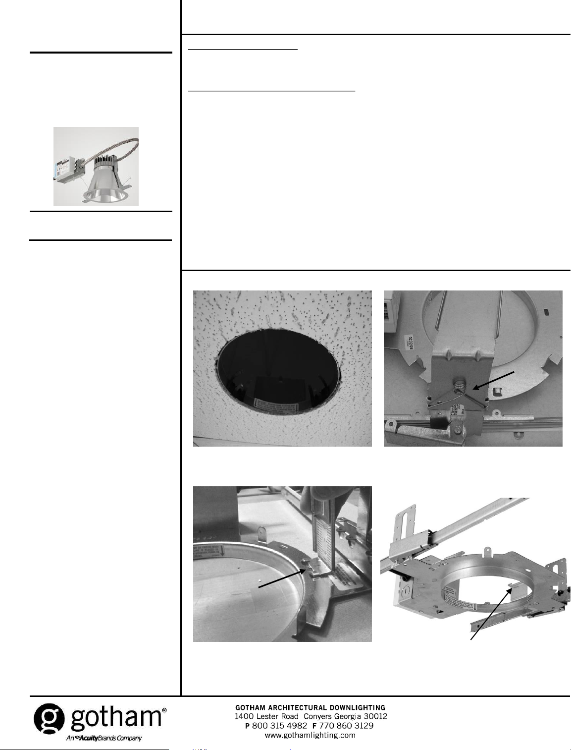
Figure 1 Figure 2
Figure 3 Figure 4
Retrofit assembly components:
1. Wiring compartment with LED driver attached and LED light engine connected with flex.
2. Trim retaining springs and brackets.
Direct LED downlighting retrofit kit instructions:
To retrofit the fixture using this product, customers must have Gotham housings (GRSF, GRSH, GRS, AFV or
LGFV) as shown in Figure 1 and subsequent photos.
1. Disconnect power to light fixture.
2. Remove existing reflector from ceiling, disconnect socket cup assembly and set aside.
3. For horizontally lamped fixtures with a yoke assembly, remove the yoke by releasing springs on both sides
of yoke as shown in Figure 2. For vertically lamped fixtures with a yoke, remove yoke by pushing each side
outward as shown in Figure 3. Discard yoke.
4. Install torsion spring retention brackets (shown in Figure 4) on mounting frame.
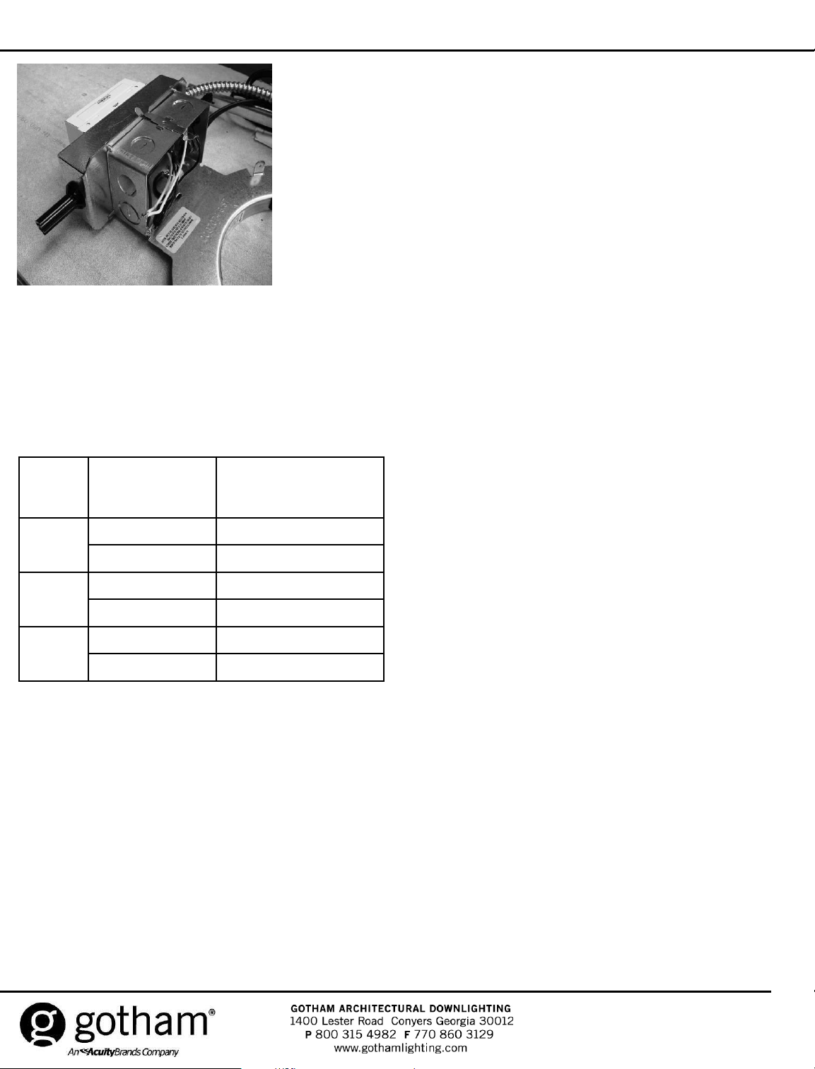
5. Remove inner junction box door and disconnect power supply. Remove outer junction box door and
discard. Pass LED retro-fit driver assembly through aperture snapping new LED driver assembly to outside
of junction box as shown is Figure 5. Wiring per diagrams below Figure 6 (120V or 277V) or Figure 7
(347V). Snap on inner junction box door.
6. Attach new LED downlight trim to LED light engine assembly, see trim instruction (CJ5201007 shipped
separately).
7. For 347V wiring see diagram below (Figure 7).
Page 3
CJ5201009 Rev. J
11/2013 3 of 8
©2010, 2011 Acuity Brands Lighting, Inc.
All Rights Reserved.
SAVE THESE INSTRUCTIONS
Use Table to determine the minimum plenum depth required to utilize Gotham EVO R.
Size Style
Minimum Plenum
Depth Required
(inches)
4"
Downlight 6.250
Wallwash 6.250
6"
Downlight 7.500
Wallwash 7.500
8"
Downlight 8.500
Wallwash 8.500
Minimum ceiling plenum depth is dependant on ceiling thickness.
Figure6
Page 4

CJ5201009 Rev. J
11/2013 4 of 8
©2010 Acuity Brands Lighting, Inc.
All Rights Reserved.
SAVE THESE INSTRUCTIONS
Figure 6
Figure 7
Page 5

Page 6

CJ5201009 Rév. J
11/2013 6 de 8
©2010, 2011 Acuity Brands Lighting, Inc.
Tous droits réservés.
CONSERVEZ CES INSTRUCTIONS
Lors de la réception, procédez à une
inspection minutieuse à la recherche de
dommages éventuels subis lors du transport,
ceux-ci doivent être portés à l'attention du
transporteur/livreur. Comparez la description
du catalogue indiquée sur le bordereau
d'emballage avec l'étiquette sur le carton afin
de vous assurer que vous avez reçu les
bonnes marchandises.
NOTICE D'INSTALLATION
EVO R
Rattrapage
RENSEIGNEMENTS IMPORTANTS SUR LA
SÉCURITÉ
Pour votre protection, lisez attentivement
AVERTISSEMENT : RISQUE D'INCENDIE OU
DE CHOC ÉLECTRIQUE. NE PAS ALTÉRER,
DÉPLACER OU RETIRER LE CÂBLAGE, LES
DOUILLES, L'ALIMENTATION OU TOUT
AUTRE COMPOSANT ÉLECTRIQUE.
AVERTISSEMENT : RISQUE D'INCENDIE OU
DE CHOC ÉLECTRIQUE. L'INSTALLATION DE
CET ENSEMBLE DE MISE À NIVEAU
NÉCESSITE UNE PERSONNE QUALIFIÉE
DANS LA MISE EN PLACE ET DANS
L'UTILISATION DU SYSTÈME ÉLECTRIQUE DU
LUMINAIRE AINSI QUE DANS LES DANGERS
ENCOURUS. SI LA PERSONNE N'EST PAS
QUALIFIÉE, NE PROCÉDEZ PAS À
L'INSTALLATION. COMMUNIQUEZ AVEC UN
ÉLECTRICIEN QUALIFIÉ.
AVERTISSEMENT : RISQUE D'INCENDIE OU
DE CHOC ÉLECTRIQUE. INSTALLEZ CE
NÉCESSAIRE UNIQUEMENT DANS LES
LUMINAIRES QUI PRÉSENTENT LES
CARACTÉRISTIQUES DE CONSTRUCTION ET
LES DIMENSIONS ILLUSTRÉES PAR LES
PHOTOGRAPHIES ET/OU LES DESSINS.
PENDANT L'INSTALLATION DU KIT, NE
FAITES PAS DE TROUS DANS LE BOÎTIER DE
CÂBLAGE OU DE COMPOSANTS
ÉLECTRIQUES ET NE MODIFIEZ PAS LES
TROUS DÉJÀ EXISTANTS.
AVERTISSEMENT : POUR ÉVITER DES
DOMMAGES OU UNE USURE DU CÂBLAGE.
N'EXPOSEZ PAS LE CÂBLAGE À DES BORDS
DE TÔLE OU D'AUTRES OBJETS
TRANCHANTS.
LE KIT DE MISE À NIVEAU DOIT ÊTRE
UNIQUEMENT INSTALLÉ À L'EMPLACEMENT
PRÉVU ET DE LA MANIÈRE APPROPRIÉE.
CONVIENT AUX EMPLACEMENTS MOUILLÉS,
SUPPORT DE PLAFOND COUVERT
UNIQUEMENT.
COMPATIBLE AVEC LES LUMINAIRES DE
TYPE « NON CI ».
COMPATIBLE AVEC LES LUMINAIRES
FERMÉS ET ENCASTRÉS.
Schéma 1 Schéma 2
Schéma 3 Schéma 4
Composants de l'ensemble de mise à niveau :
1. Compartiment de câblage avec conducteur DEL fixé et moteur du luminaire DEL connecté au réflecteur.
2. Supports et ressorts de retenue de la garniture.
Instructions du kit de mise à niveau de plafonnier DEL direct :
Pour mettre à niveau le luminaire à l'aide de ce produit, les clients doivent posséder des boîtiers Gotham (GRSF, GRSH, GRS,
AFV ou LGFV) conformément au schéma 1 et aux photos suivantes.
1. Coupez l'alimentation du luminaire.
2. Retirez le réflecteur existant du plafond, débranchezl'ensemble du boîtier de douille et mettez-les de côté.
3. Pour des luminaires à ampoules horizontales avec un ensemble de culasse, retirez la culasse en dégageant les ressorts
des deux-côtés de celle-ci, conformément au schéma 2. Pour des luminaires à ampoules verticales avec une culasse,
retirez la culasse en poussant chaque côté vers l'extérieur, conformément au schéma 3. Retirez la culasse.
4. Installez les supports de retenue du ressort de torsion (conformément au schéma 4) sur le cadre de montage.
5. Retirez la trappe intérieure du boîtier de raccordement et débranchez l'alimentation. Retirez la trappe extérieure du
boîtier de raccordement et jetez-la. Faites passer l'ensemble du conducteur de mise à niveau DEL à travers l'ouverture
en enclenchant le nouvel ensemble du conducteur DEL dans la partie externe du boîtier de raccordement conformément
au schéma 5. Le câblage doit respecter les schémas ci-dessous : schéma 6 (120V ou 277V) ou schéma 7 (347V).
Emboîtez la trappe intérieure du boîtier de raccordement.
6. Fixez la nouvelle garniture de plafonnier DEL à l'ensemble du moteur luminaire DEL, voir les instructions de la garniture
(CJ5201007 expédié séparément).
7. Pour le câblage 347 V, voir le diagramme ci-dessous (schéma 7).
Page 7

CJ5201009 Rév. J
11/2013 7 de 8
©2010, 2011 Acuity Brands Lighting, Inc.
Tous droits réservés.
CONSERVEZ CES INSTRUCTIONS
Utilisez le tableau pour déterminer la profondeur minimum requise du plénum pour
utiliser Gotham EVO R.
Taille Style
Profondeur minimal
requise du plénum
(en pouces)
4 po
Plafonnier 6,250
Lèche-mur 6,250
6 po
Plafonnier 7,500
Lèche-mur 7,500
8 po
Plafonnier 8,500
Lèche-mur 8,500
La profondeur minimale du plénum du plafond dépend de l'épaisseur du plafond.
Schéma 6
Page 8

CJ5201009 Rév. J
11/2013 8 de 8
©2010 Acuity Brands Lighting, Inc.
Tous droits réservés.
CONSERVEZ CES INSTRUCTIONS
Schéma 6
Schéma 7
 Loading...