

Page 1
INSTALLATION INSTRUCTIONS
Emergency Ballast
Upon receipt, thoroughly inspect for any
freight damage which should be brought to
the attention of the delivery carrier. Compare
the catalog description listed on the packing
slip with the label on the carton to ensure you
have received the correct merchandise.
IMPORTANT SAFETY INFORMATION
For Your Protection, Read Carefully
Figure 1
Figure 2
Test Switch/Pilot Light Box
Figure 2
Prior to Installation
1. Install rough-in section as detailed on separate instruction sheet.
2. Determine line voltage to fixture (switched
and unswitched power requirements)
.
3. Verify correct ballast/lamp combination.
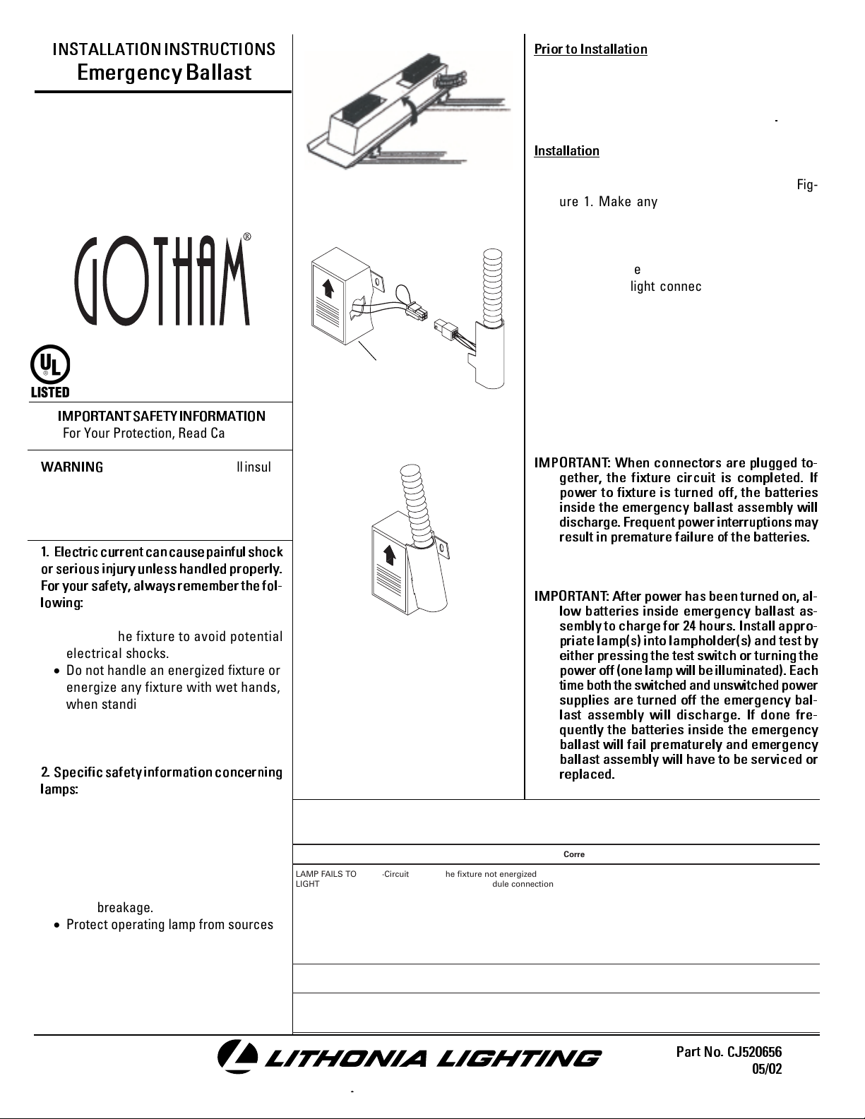
Installation
1. Pivot emergency ballast assembly onto mounting rails of rough-in section as shown in Figure 1. Make any necessary vertical adjustments to assure that the bottom of the roughin section is flush or slightly above (1/8" max.)
the ceiling line.
2. Make emergency ballast assembly and test
switch/pilot light connection by plugging the
two connectors together (see Figure 2).
3. Push wires and connectors into opening of
test switch/pilot light box fastened to reflector. Install flex connector into box making sure
that flex is oriented in direction of arrow (see
Figure 3).
WARNING
- Risk of fire. Do not install insulation within 3 inches of fixture sides or wiring
compartment, nor above the fixture in such
a manner as to entrap heat.
1. Electric current can cause painful shock
or serious injury unless handled properly.
For your safety, always remember the fol-
lowing:
· Turn off the power supply.
· Ground the fixture to avoid potential
electrical shocks.
· Do not handle an energized fixture or
energize any fixture with wet hands,
when standing on a wet or damp surface, or in water.
· Double check all electrical connections
to be sure they are tight and correct.
2. Specific safety information concerning
lamps:
· Match wattage of fixture and lamp exactly.
· Do not remove or insert lamp when power
is on.
· Do not scratch glass or subject lamp to
undue pressure as either may cause
lamp breakage.
· Protect operating lamp from sources
of moisture.
Figure 3
TRAHCGNITOOHSELBUORT
motpmySesuaCelbissoPnoitcAevitcerroC
OTSLIAFPMAL
THGIL
pmalytluaF·
tuptuotsallabroeniL·
tsallabytluaF·
TUOSEOGPMAL
GNITHGILRETFA
NOSELCYCPMAL
FFODNA
pmalytluaF· nahtrehtarmotpmyssihttibihxelliwpmalayllanoisaccO·
wolooterutarepmettneibmA·
hgihootegattawpmaL·
wolegatlovtuptuotsallaB·
IMPORTANT: When connectors are plugged to-
gether, the fixture circuit is completed. If
power to fixture is turned off, the batteries
inside the emergency ballast assembly will
discharge. Frequent power interruptions may
result in premature failure of the batteries.
IMPORT ANT : After power has been turned on, al-
low batteries inside emergency ballast as-
sembly to charge for 24 hours. Install appro-
priate lamp(s) into lampholder(s) and test by
either pressing the test switch or turning the
power off (one lamp will be illuminated). Each
time both the switched and unswitched power
supplies are turned off the emergency bal-
last assembly will discharge. If done fre-
quently the batteries inside the emergency
ballast will fail prematurely and emergency
ballast assembly will have to be serviced or
replaced.
.snoitcaevitcerrocdnasesuacelbissopfotsilgniwollofeht
dezigrenetonerutxifehtgnideeftiucriC·
noitcennoceludomrotiucricnirorregniriW·
erutxifotesolcootsinoitalusnI·
.tcerroc
.enowenahtiw
.ytiunitnoctiucrickcehC·
.gnisuohnideificepsegattawpmalllatsnI·
nimelborpehtetacol,noitidnocdoognimeesyehtfI.eludomni-emarfropmalehtotegamadelbisivynarofkcehC
.dezigrenesitiucrictahterusneotesufrorekaerbtiucrickcehC·
erasnoitcennoctahterusneotxobecilpserutxifenimaxE·
ylbareferp,pmalrehtonaetutitsbusdnapmalytluafehtevomeR·
lanigiroehtecalper,sthgilpmalehtfI.thgilotnwonksitahteno
.egatlovtiucricnepokcehC.erutxiftaegatlovenilkcehC·
.snoitidnoclatnemnorivnegnitsixetsniagagnitartsallabkcehC·
.pmalwenaetutitsbuS.thgilotgniliafylpmis
)"3tsaelta(eludomdnuoramorfnoitalusnievomeR·
.egatlovtiucricnepokcehC.erutxifehttaegatlovenilkcehC·
ONE LITHONIA WAY, CONYERS, GEORGIA 30012, TELEPHONE 1-800-315-4982, FAX 770-860-3129
DOWNLIGHTING & TRACK SYSTEMS
www.lithonia.com IN CANADA: 1100 50TH AVE., LACHINE, QUEBEC H8T 2V3
Part No. CJ520656
05/02
 Loading...