

Page 1
INSTALLATION INSTRUCTIONS
®
!
Elevations
®
Performance Decorative Pendant
PDPF, Cand
éo® and Ice
Upon receipt, thoroughly inspect for any
freight damage which should be brought to
the attention of the delivery carrier. Compare
the catalog description listed on the packing
slip with the label on the carton to ensure you
have received the correct merchandise.
IMPORTANT SAFETY INFORMATION
For Your Protection, Read Carefully
1. Electric current can cause painful shock
or serious injury unless handled properly. For your safety, always remember
the following:
• Turn off the power supply.
• Ground the fixture to avoid potential
electrical shocks.
• Do not handle an energized fixture or
energize any fixture with wet hands,
when standing on a wet or damp surface, or in water.
• Double check all electrical connections
to be sure they are tight and correct.
®
SA VE THESE INSTRUCTIONS
Direct Mount (PDPF, Candéo and Ice)
I. Ground Prep
1. Temporarily remove top cap and any round decorative piece to expose
support bracket.
2. Removing socket assembly from box, attach socket cup to reflector per trim
instruction.
3. Route wires from reflector/socket assembly through bottom of housing and
plug into ballast assembly. Attach the ballast assembly to top of housing with
the attached screws.
4. Route the (3) ballast source wires and housing ground through the center
hole on the exposed support bracket.
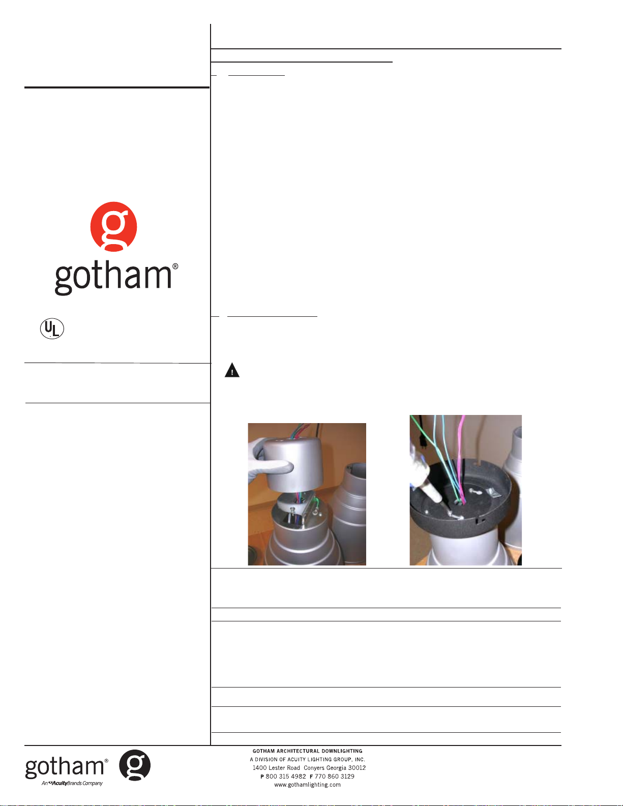
5. Route conductors through top cap, replace the top cap, leaving screws
protruding 1/2 in. through keyholes (See Figure 1A).
6. Separate j-box pan from canopy by loosening the (3) side screws. Twist apart
to separate. VERIFY THAT THE ROUND DECORATIVE ELEMENT (IF REQUIRED) IS ON PRIOR TO CONTINUING!
7. Route socket conductors from fixture through canopy piece hole and place
canopy over extended screws on fixture top (See Figure 1B).
8. Adjust canopy piece and fixture cap until both screw heads are fully captured
on both parts. Tighten both screws in position. SCREWS MUST BE COMPLETELY FORWARD IN KEYHOLES FOR FIXTURE TO BE CENTERED! Adjust if
necessary.
II. Ceiling Installation
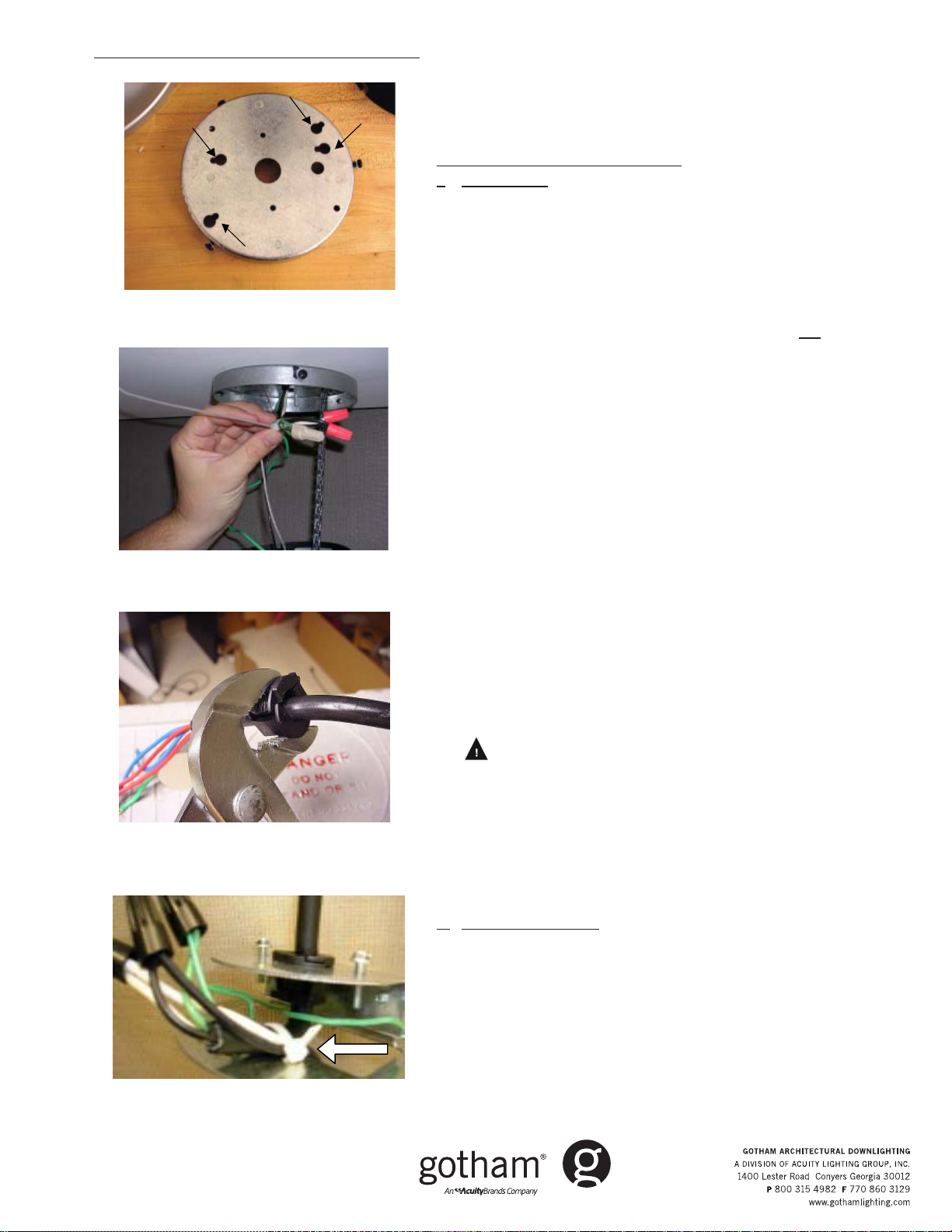
8. Hang mounting pan by routing j-box wires through back of pan, and using
either 3.5 or 4.5 inch key holes, secure to j-box (See Figure 1C).
9. Hook the safety chain to the canopy's support tab to suspend the entire
assembly. Make all required electrical connections using wire-nuts.
WARNING! Possible falling hazard and risk of serious injury. Gather both
cord and socket leads into tie strap strain relief so that a minimum of two
inches of cord conductors with socket conductors are pulled inside tie strap.
Pull tie strap tight enough to strain relieve all connections. Trim excess strap
material (See Figure 1D).
Figure 1B
Figure 1A
2. Specific safety information concerning
lamps:
• Match wattage of fixture and lamp ex-
actly.
• Do not remove or insert lamp when power
is on.
• Do not scratch glass or subject lamp to
undue pressure as either may cause
lamp breakage.
• Protect operating lamp from sources
of moisture.
ivynarofkcehC
motpmySesuaCelbissoPnoitcAevitcerroC
OTSLIAFPMAL
THGIL
TUOSEOGPMAL
GNITHGILRETFA
NOSELCYCPMAL
FFO
DNA
TRAHCGNITOOHSELBUORT
omrotiucricnirorregniriW·
pmalytluaF·
tuptuotsallabroeniL·
tsallabytluaF·
pmalytluaF· naht
wolooterutarepmettneibmA·
erutxifotesolcootsinoitalusnI·
hgihootegattawpmaL·
wolegatlovtuptuotsallaB·
.snoitcaevitcerrocdnasesuacelbissopfotsilgniwollofeht
dezigrenetonerutxifehtgnideeftiucriC·
noitcennocelud
.tcerroc
.enowenahtiw
ehC·
enilkcehC·
.ytiunitnoctiucrickc
.pmalwenaetutitsbuS.thgilotgniliafylpmis
.gnisuohnideificepsegattawpmalllatsnI·
nimelborpehtetacol,noitidnocdoognimeesyehtfI.eludomni-emarfropmalehtotegamadelbis
renesitiucrictahterusneotesufrorekaerbtiucrickcehC·
.dezig
erasnoitcennoctahterusneotxobecilpserutxifenimaxE·
ylbareferp,pmalrehtonaetutitsbusdnapmalytluafehtevomeR·
lanigiroehtecalper,sthgilpmalehtfI.thgilotnwonksitahteno
.egatlovtiucricnepokcehC.erutxiftaegatlovenilkcehC·
.snoitidnoclatnemnorivnegnitsixetsniagagnitartsallabkcehC·
rehtarmotpmyssihttibihxelliwpmalayllanoisaccO·
)"3tsaelta(eludomdnuoramorfnoitalusnievomeR·
.egatlovtiucricnepokcehC.erutxifehttaegatlov
Part No. CJ52008
©2005 Gotham Rev. B 11/07
Elevations® - Part I
Page 2
Fixture connections and hanging instructions
!
1/2
4
1/2
1/2
3
1/2
4
3
Figure 1C
Figure 1D
Figure 2C
10. Position the complete assembly to align the "V" notch on the
canopy with the "V" notch inside the mounting pan. Tuck in all
wires, close assembly to mounting pan and twist to engage
screws into L-slots (See Figure 1D).
11. Tighten screws. INSTALLATION COMPLETE.
Cord Mount (PDPF, Candéo and Ice)
I. Ground Prep
1. Temporarily remove top cap and any round decorative piece to
expose support bracket.
2. Removing socket assembly from box, attach socket cup to trim
(per trim instructions).
3. Route wires from reflector/socket assembly through bottom of
housing and plug into ballast assembly. Attach the ballast assembly to top of housing with the attached screws.
4. Bundle ballast source wires under bracket (do
not pass wires
through bracket center hole).
5. Replace the top cap and round decorative piece, leaving
screws loose for later steps.
6. Measure desired hanging length from ceiling to top of fixture,
then subtract the thickness of the canopy and add 6 inches.
**Ceiling suspension length - canopy thickness + 6 inches =
cord length.**
7. Strip off 4 inches of cord jacket to expose inner conductors.
Strip ½ inch from each conductor to expose copper.
8. Secure the provided strain relief bushing with a minimum of 2
inches above the stripped edge of the cord. Use pliers or vicegrips to crimp around the cord jacket – flat side facing up. IF
ADJUSTMENT IS REQUIRED, USE EITHER A FLATHEAD SCREWDRIVER TO PRY-OFF BUSHING AND RECRIMP, OR CUT BUSHING
OFF AND USE EXTRA ONE PROVIDED (See Figure 2C).
9. Remove the fixture cap to expose support bracket and to route
cord through top center hole.
10. VERIFY CORD IS ROUTED THROUGH CAP AND ANY ROUND
DECORATIVE PIECES ARE ON FIXTURE! Align cord-attached
bushing to bracket hole and press firmly into support bracket
until all three snaps engage. Flat ledge of bushing should sit
flush with bracket surface.
11. WARNING! Possible falling hazard and risk of serious
injury. Gather both cord and socket leads into tie strap strain
relief so that a minimum of two inches of cord conductors with
socket conductors are pulled inside tie strap. Make connections with wire nuts. Pull tie strap tight enough to strain relieve
all connections. Trim excess strap material (See Figure 2D).
12. Separate j-box mounting pan from top of canopy by loosening
the 3 side screws, twisting and removing.
II. Ceiling Installation
13. Hang mounting pan by routing j-box wires through back of
pan, and using either 3.5 or 4.5 inch key holes, secure to j-box
(See Figure 1C).
14. With canopy and fixture suspended on cord, make power
connections using wire nuts.
15. Align the “V” notch on the outer canopy with the “V” notch
inside the mounting pan. Tuck in all wires, close assembly to
mounting pan and twist to engage screws into L-slots (See
Figure 1D).
Figure 2D
Part No. CJ52008
©2005 Gotham Rev B. 11/07
Elevations®- Part I
16. Tighten screws. INSTALLATION COMPLETE.
 Loading...