

Page 1
Incito DMX512 / RDM Field Installation Manual
converter has a resolution of 4000 steps from minimum to maximum.
It’s configurable to respond
1 of 11
April 2013
Description
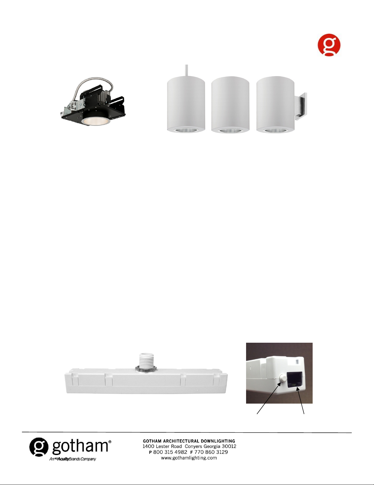
The Gotham Incito downlighting family utilizes DMX512 protocol via a DMX converter module
(DMXR option (HPEPP module), see figure 1) over Category 5 cable and has the capability to
communicate with the lighting controller (processor, light board, Easyl controller, etc.) via RDM
(Remote Device Management). The Remote Device Management Protocol (RDM) permits
intelligent bi-directional communication between devices from multiple manufacturers utilizing a
modified DMX512 data link. RDM is an EF 1.0 implementation of ANSI E1.11. RDM permits a
console or other controlling device to discover and then configure, monitor, and manage
intermediate and end-devices connected through a DMX512 network. RDM provides for
intelligent control of devices on a DMX512 network, which has not been previously available
outside of proprietary networks. This standard specifies: the physical layer and timings, device
discovery process and algorithms, message structure and communication. The DMX to 0-10V
to either one DMX slot or two DMX slots: when one slot is used to control it, the converter will up
convert the 255 DMX steps to the full output resolution by fading smoothly between the steps.
When 2 DMX slots are used the converter will provide user access to the full 4000 steps.
Contents
Safety Information 2 - 3
Protocols Supported 4
Installation 4 - 5
DMX512 / RDM Pinout Configuration 6
Incito 6” Downlight Wiring Diagram 7
Incito 6” Cylinder Wiring Diagram 8
HPEPP Converter Module (DMXR Option) Instructions 9 - 11
Glossary of Terms 11
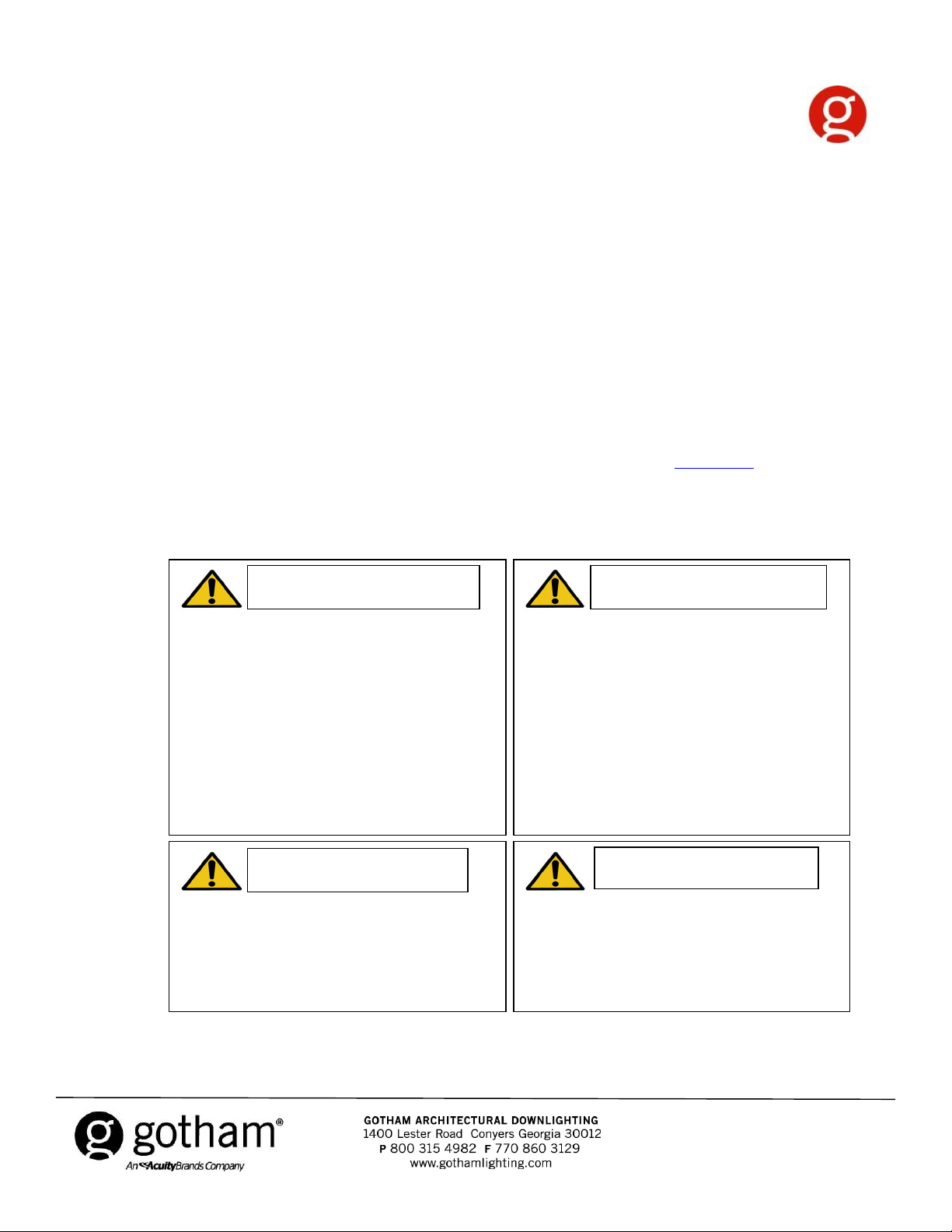
Figure 1, DMXR Option (HPEPP module)
Pushbutton
RJ45 Port
(both ends)
CJ520003 Rev. E
©2012 Acuity Brands Lighting, Inc.
All Rights Reserved.
Page 2
IMPORTANT SAFETY INFORMATION
cuts/abrasions, and other hazards please read all warnings and instructions included with and on the fixture box
will depend on
WARNING
RISK OF ELECTRI
C SHOCK
WARNING
RISK OF BURN
2 of 11
Disconnect or turn off power before
Allow lamp/fixture to cool before
CAUTION
RISK OF INJURY
CAUTION
For Your Protection, Read Carefully
• To reduce the risk of death, personal injury or property damage from fire, electric shock, falling parts,
and all fixture labels.
• Before installing, servicing, or performing routine maintenance upon this equipment, follow these general
precautions.
• Installation and service of luminaires should be performed by a qualified licensed electrician.
• Maintenance of the luminaires should be performed by person(s) familiar with the luminaires’ construction and
operation and any hazards involved. Regular fixture maintenance programs are recommended.
• It will occasionally be necessary to clean the outside of the refractor/lens. Frequency of cleaning
ambient dirt level and minimum light output which is acceptable to user. Refractor/lens should be washed in a
solution of warm water and any mild, non-abrasive household detergent, rinsed with clean water and wiped
dry. Should optical assembly become dirty on the inside, wipe refractor/lens and clean in above manner,
replacing damaged gaskets as necessary.
• DO NOT INSTALL DAMAGED PRODUCT! This luminaire has been properly packed so that no parts should have
been damaged during transit. Inspect to confirm. Any part damaged or broken during or after assembly should
be replaced.
• Recycle: For information on how to recycle LED electronic products, please visit www.epa.gov.
• These instructions do not purport to cover all details or variations in equipment nor to provide every possible
contingency to meet in connection with installation, operation, or maintenance. Should further information be
desired or should particular problems arise which are not covered sufficiently for the purchaser’s or owner’s
purposes, this matter should be referred to Acuity Brands Lighting, Inc.
installation or servicing.
Verify that supply voltage is correct by
comparing it with the luminaire label
information.
Make all electrical and grounded
connections in accordance with the
National Electrical Code (NEC) and any
applicable local code requirements.
All wiring connections should be capped
with UL approved recognized wire
connectors.
Wear gloves and safety glasses at all
times when removing luminaire from
carton, installing, servicing or performing
maintenance.
Avoid direct eye exposure to the light
source while it is on.
handling. Do not touch enclosure or light
source.
Do not exceed maximum wattage
marked on luminaire label.
Follow all manufacturer’s warnings,
recommendations and restrictions for:
driver type, burning position, mounting
locations/methods, replacement and
recycling.
Keep combustible and other materials
that can burn, away from lamp/lens.
Do not operate in close proximity to
persons, combustible materials or
substances affected by heat or drying.
CJ520003 Rev. E
©2012 Acuity Brands Lighting, Inc.
All Rights Reserved.
Page 3
IMPORTANT SAFETY INFORMATION
CAUTION: RISK OF PRODUCT DAMAGE
3 of 11
performance.
For Your Protection, Read Carefully
Never connect components under load.
Do not mount or support these fixtures in a manner that can cut the outer jacket or damage wire
insulation.
Unless individual product specifications deem otherwise: Never connect an LED product directly to a
dimmer packs, occupancy sensors, timing devices, or other related control devices. LED fixtures must be
powered directly off a switched circuit.
Unless individual product specifications deem otherwise: Do not restrict fixture ventilation. Allow for
some volume of airspace around fixture. Avoid covering LED fixtures with insulation, foam, or other
material that will prevent convection or conduction cooling.
Unless individual product specifications deem otherwise: Do not exceed fixtures maximum ambient
temperature.
Only use fixture in its intended location.
LED products are Polarity Sensitive. Ensure proper Polarity before installation.
Electrostatic Discharge (ESD): ESD can damage LED fixtures. Personal grounding equipment must be
worn during all installation or servicing of the unit.
Do not touch individual electrical components as this can cause ESD, shorten lamp life, or alter
Please see product specific installation instructions for additional warnings or any applicable FCC or other regulatory
Failure to follow any of these instructions could void product warranties. For a complete listing of product Terms and
Some components inside the fixture may not be serviceable. In the unlikely event your unit may require
service, stop using the unit immediately and contact an ABL representative for assistance.
Always read the fixtures complete installation instructions prior to installation for any additional fixture
specific warnings.
statements.
Conditions, please visit www.acuitybrands.com.
CJ520003 Rev. E
©2012 Acuity Brands Lighting, Inc.
All Rights Reserved.
Page 4
Protocols Supported
logarithmic)
Default DMX/ RDM Settings
4 of 11
The DMXR module supports the current DMX standard ANSI E1.11 DMX512-A and is backwards
compatible to USITT DMX512 (1990). Also supported is ANSI E1.20 RDM (Remote Device
Management).
Installation
Default Settings Table
DMX Address 001
DMX Channel 1-DMX Slot (8-bit level)
RDM Personality Linear Curve
Logarithmic curve (Overall
fixture response will be
Incito Driver
Loss of DMX Signal Hold last level forever
Network Setup
• Use the pinout configuration on page 6 to connect to the lighting controller.
• Including the DMX512 source, a maximum of 32 Incitos per LAN is allowed. Consult factory
for applications requiring more than 32 Incitos per LAN. Note: One universe fed into an optosplitter creates multiple LANs. See Figure 2
• Using the appropriate category cable, daisy chain between luminaires and back to the control
system. Note: No T-TAPS, STARS (except by an opto-splitter) or Ys allowed.
• A termination plug is included with each luminaire. Ensure the termination plug is installed into
the last luminaire in the daisy chain. If this component is not installed the luminaires will exhibit
erratic/intermittent behavior.
• 2000 feet is the maximum distance to the furthest luminaire.
CJ520003 Rev. E
©2012 Acuity Brands Lighting, Inc.
All Rights Reserved.
Page 5

Figure 2 - DMX512 Universe Example
5 of 11
Lighting
Controller
5 Pin XLR Male to
RJ45 Adaptor
Incito Incito Incito
HPEPP, see fig. 2
Incito
Daisy Chain CAT5
S
p
l
i
t
t
e
r
Incito Incito
Incito Incito
Incito Incito
Pathway #1009 DMX/RDM Splitter
Incito
Incito
Incito
Incito
Incito
Incito
Notes:
1. Do not utilize T-TAPS,
STARS or Y’s
2. Ensure termination plug is
utilized at the end of each
daisy chain
Figure 2, DMXR Option (HPEPP Module)
Pushbutton
RJ45 Port
(both ends)
CJ520003 Rev. E
©2012 Acuity Brands Lighting, Inc.
All Rights Reserved.
Page 6

DMX512/RDM Pinout Configuration (ANSI E1.11)
DMX512 Function per ANSI E1.11
1
white / orange
Data 1 +
2
orange
Data 1 -
3
white / green
Data 2 + (not used for Incito)
6
green
Data 2 - (not used for Incito)
4
blue
Not Assigned
5
white / blue
Not Assigned
7
white / brown
Data 1 common (0 v)
8
brown
Data 2 common (0 v)
DMX512 Function per ANSI E1.11
1
white / orange
Data 1 +
6 of 11
2
orange
Data 1 -
3
white / green
Data 2 + (not used for Incito)
4
blue
Not Assigned
5
white / blue
Not Assigned
6
green
Data 2 - (not used for Incito)
7
white / brown
Data 1 common (0 v)
8
brown
Data 2 common (0 v)
*CAT5, CAT5E, CAT6 cable must be spliced into XLR cable from console
or utilize 5 pin XLR to RJ45 adaptor.
DMX Network Cat-5 / Cat-5e / Cat 6 Wiring (sorted by pair)
Pin (Wire) # Wire Color
Used in Incito DMXR (HPEPP)
DMX Network Cat-5 / Cat-5e / Cat 6 Wiring (sorted by pin #)
Pin (Wire) # Wire Color
Used in Incito DMXR (HPEPP)
CJ520003 Rev. E
©2012 Acuity Brands Lighting, Inc.
All Rights Reserved.
Page 7

HPEPP Module (DMXR Option)
Incito 6” Downlight Wiring Diagram
HPEPP Module (DMXR Option)
7 of 11
0-10V LED Driver
Thermal
Protector
To LEDs
DMX In
*On the DMXR downlight option, the HPEPP module
will be installed at the factory to the luminaire’s
junction box.
DMX Out or
termination
plug
CJ520003 Rev. E
©2012 Acuity Brands Lighting, Inc.
All Rights Reserved.
Page 8

Incito 6” Cylinder Wiring Diagram
8 of 11
*On the cylinder with DMXR option, the HPEPP module ships
separately and must be installed to the junction box in ceiling/wall
DMX In
DMX Out
HPEPP Module (DMXR Option)
Or termination
plug (see
glossary)
0-10V LED Driver
CJ520003 Rev. E
©2012 Acuity Brands Lighting, Inc.
All Rights Reserved.
Page 9

Configuring HPEPP Interface Module (DMXR Option)
mode, then return to step 1.
9 of 11
The following functions can be configured using either RDM (recommended) or the on-board
pushbutton interface (see figure 1):
• Button override On/Off
• Configured to respond to the DMX dimming level using either a linear or logarithmic
dimming curve.
• Configured to respond to either 8-bit or 16-bit DMX levels.
• Set DMX addresses
• Configure behavior on loss of DMX signal
ONBOARD BUTTON PROGRAMMING INSTRUCTIONS
PLEASE READ ALL 7 STEPS BEFORE PROGRAMMING
1. Enter programming mode by pressing & holding the button until the LED flashes rapidly.
Release the button (see Figure 1).
2. To enter a specific programming mode, (see Function Table for modes) press the button the
same number of times as the desired function. For example, press the button 3 times for function
3.
3. The LED will indicate the function’s current setting by blinking the LED. For example, 2 blinks
for function 3 is 2 DMX slots Linear. To edit the options of the currently selected function, proceed
to step 4 before the LED blink sequence repeats 10 times. To exit the current function or to
change to a different function, wait for the LED blink sequence to repeat 10 times. This will exit
editing mode. Or, press and hold the button until the LED blinks rapidly. This enters confirmation
4. To edit each specific option, press the button to increment current value to the next item in the
function table for the particular option you wish to modify. For example, in programming mode 3
(Configure DMX Channel Footprint) to change from option 1, 1-DMX Slot Linear to option 2, 2DMX Slots Linear, press the button 1 time. The LED will blink the new option value 10 times, and
then exit programming mode. If confirmation of settings is not performed during this process, the
HPEPP will exit without saving new value. Pressing the confirmation sequence acknowledges
acceptance of the new option value.
5. Next, exit edit mode and proceed to confirmation mode by pressing and holding the button until
the LED flashes rapidly. Release the button.
6. Re-enter the edited function number as final confirmation of the edited options.
7. The LED will blink twice to indicate acceptance of the new option values. If two flashes are not
seen, repeat the entire process.
Notes:
- If there are 20 seconds of inactivity (no button presses) at any point in this process,
the edit process will cancel and exit, and all changes will be lost.
- A value of 0 is indicated by 10 LED blinks.
- When acknowledging a selected value by blinking the LED 10 times, there will be a
1 second pause after the 10th blink, then the cycle will repeat.
- When indicating the selected menu value by blinking the LED, during the last blink
in the cycle the LED will remain on for 1 second. All other blinks in the cycle will be
for 1/2 second.
- Edit mode will always increment value being flashed for each button press.
- Also make sure you set the luminaire type at controller to match the setting for
HPEPP.
CJ520003 Rev. E
©2012 Acuity Brands Lighting, Inc.
All Rights Reserved.
Page 10

DETAILED FUNCTION TABLE
10 of 11
If changing the MSD from “0” to “2”, while the HPEPP is flashing the MSD 10 times (zero), press the
Function 1 - Enable Button Override (aka Button Mode, Focus)
4 blinks = button override disabled
5 blinks = button override enabled
When button override is enabled, each short button press (not in programming mode) will step the
output through an OFF, 50%, 100% light level cycle.
Note: A button press longer that a quick tap will put the unit in programming mode. Take care not to
accidentally put the unit in programming mode.
Function 2 = Set DMX Address
The LED will blink each digit of the current DMX address. (the digits will blink twice a second.)
Blink 1st digit, 1 second pause - blink 2nd digit, 1 second pause - blink 3rd digit, 3 second pause –
repeat
The new address is set by pressing desired digit change during the flashing of that digit.
For example:
• the most significant digit for address 206 it’s “2”.
• address 8 (or 008, sometimes DMX addresses are documented with all three digits) is “8”
• address 17 (or 017) is “1”
button twice. Once done entering the first digit (most significant digit) do not press the button for 3
seconds. The unit will then confirm the first digit by blinking the LED twice. Next, enter the second
digit the same way as the first while the second digit is flashing. (if applicable), then the third digit. (if
applicable) Once all digits are entered, press and hold the button to exit programming mode and
confirm the changes. (See step 5 above).
Note: 0 is indicated by 10 blinks. If you change any of the digits, the HPEPP will flash the new value
for the digit and process to next lower byte.
Function 3 = Configure DMX Channel Footprint/RDM Personality
1 blink = 8-Bit Linear No Relay(1 chan)
2 blinks = 16-Bit Linear No Relay((2 chan)
3 blinks = 8-Bit Log No Relay(1 chan)
4 blinks = 16-Bit Log No Relay(2 chan)
5 blinks = 8-Bit Linear w/Relay(2 chan)
6 blinks = 8-Bit Log w/Relay(2 chan)
7 blinks = 16-Bit Linear w/Relay(3 chan)
8 blinks = 16-Bit Log w/Relay(3 chan)
CJ520003 Rev. E
©2012 Acuity Brands Lighting, Inc.
All Rights Reserved.
Page 11

DETAILED FUNCTION TABLE, Cont’d
11 of 11
slots.
Function 4 = Configure behavior on loss of DMX Signal
1 blink = Hold last level forever
2 blinks = Fade to off over 1 second immediately
3 blinks = Hold last level 1 minute, then fade to off over 1 second
4 blinks = Fade to 100% over 1 second immediately
5 blinks = Hold last level 1 minute, then fade to 100% over 1 second
Gotham Technical Support: 1-800-315-4982
Glossary of Terms
Lighting controller: is an electronic device used in theatrical lighting design to control multiple
lights at once. All lighting control consoles can control dimmers which control the intensity of the
lights. A lighting controller can be a console type processor such as the Pathway CognitoTMor a
wall controller such as an EasylTM.
DMX512: is a standard for digital communication networks that are commonly used to control
stage lighting and effects.
Slot: a sequentially numbered framed byte in a DMX512 packet. A single Universe contains a
maximum of 513 Slots, starting at slot 0. Slot 0 is the START Code. Slots 1 through 512 are data
Slot Footprint: the number of data slots used by a product in its operation. Note: A 24 way
dimmer rack may have a footprint of 24, it may be more if some slots are used to provide
additional control functions using NULL START Code packets. Automated luminaires usually
require a Slot Footprint of greater than one.
Universe: a DMX512 data link originating from a single DMX512 source. Control of up to 512
DMX512 data slots comprises a single universe.
Daisy chain: is a wiring scheme in which multiple devices are wired together in sequence or in a
ring.
RDM (Remote Device Management): is a protocol enhancement to USITT DMX512 that allows
bi-directional communication between a lighting or system controller and attached RDM
compliant devices over a standard DMX line. This protocol will allow configuration, status
monitoring, and management of these devices in such a way that does not disturb the normal
operation of standard DMX512 devices that do not recognize the RDM protocol.
Termination plug: is used when you are using several DMX luminaires on a single DMX line
(Universe). It removes noise and flickering on the DMX line which improves the reliability of the
DMX system. When a DMX signal has travelled to the end of the DMX line, if not terminated, will
exhibit what is referred to as a “shadow” signal bouncing back along the line which can cause
many problems with you DMX luminaires. The longer the DMX cable run the greater the risk of
getting signal bounce back.
CJ520003 Rev. E
©2012 Acuity Brands Lighting, Inc.
All Rights Reserved.
 Loading...