

GO Systemelektronik BlueSense User Manual

Manual
BlueSense
Transducer
Version of this manual: 3.81 en
www.go-sys.de

BlueSense
GO Systemelektronik GmbH Faluner Weg 1 24109 Kiel Germany Tel.: +49 431 58080-0 Fax: -58080-11
Page 2 / 58
www.go-sys.de info@go-sys.de
Copyright
This manual contains information which is the intellectual property of GO Systemelektronik GmbH.
The user is obliged to use this information exclusively to run the instrument. It is not permitted to pass this
information to third parties. Reproducing, copying, editing or extracting the manual contents is only allowed
with the express permission of GO Systemelektronik GmbH.
Changes
GO Systemelektronik GmbH retains the right to modify the contents of the manual without prior notice.
Liability exclusion
GO Systemelektronik GmbH takes no responsibility for correct system operation under all possible operating
conditions. It is not possible to guarantee that the software will function completely without error under all
possible circumstances. GO Systemelektronik GmbH therefore disclaims all liability for any direct or indirect
damage resulting from system operation or the contents of this manual.
Product observance
Within the scope of our obligation for product observance GO Systemelektronik GmbH will endeavour to warn
third parties about all identified dangers which could arise from the interaction between hardware and software and from the use of other components. Effective product observance is only possible with adequate
information from the end user about the planned field of application and the hardware and software used. If
the conditions of use change or if the hardware or software are changed, due to the complex relationships
between hardware and software it is no longer possible to describe all possible dangers and their effects on
the total system, in particular on our system. This manual does not describe every possible property and
combination of the system. For further information, please contact GO Systemelektronik GmbH.
Manufacturer’s declaration
When installing the system it is necessary to ensure correct electrical connection, protection against moisture
and foreign bodies and excessive condensation, and system heating which can arise from both correct and
incorrect use. It is the responsibility of the installer to ensure that the correct installation conditions are provided.
Creation date: 14.6.2017
Described firmware version: 3.08
Version of this manual: 3.81 en
Article number of this manual: DOC 485 0001-E-3.81-BDA
File name: Manual_BlueSense_Transducer_V3p81_en.pdf
© GO Systemelektronik GmbH
Faluner Weg 1
24109 Kiel
Allemagne
Tel.: +49 431 58080-0
Fax: +49 431 58080-11
www.go-sys.de
info@go-sys.de

BlueSense
GO Systemelektronik GmbH Faluner Weg 1 24109 Kiel Germany Tel.: +49 431 58080-0 Fax: -58080-11
Page 3 / 58
www.go-sys.de info@go-sys.de
blank page

BlueSense
GO Systemelektronik GmbH Faluner Weg 1 24109 Kiel Germany Tel.: +49 431 58080-0 Fax: -58080-11
Page 4 / 58
www.go-sys.de info@go-sys.de
Table of Contents
1 Overview .......................................................................................................................................................................................................... 6
2 Technical Data and Connection Diagrams ................................................................................................................................................... 8
2.1 Technical Data ........................................................................................................................................................................................ 8
2.2 Connection Diagram 1 Control Parameter ............................................................................................................................................ 9
2.3 Connection Diagram 2 Control Parameter .......................................................................................................................................... 10
2.4 Sensor Terminal Connection Diagram ................................................................................................................................................ 11
2.5 Notes on the Pulse/Digital Inputs ......................................................................................................................................................... 12
2.6 Hazard Note ........................................................................................................................................................................................... 12
3 Commissioning ............................................................................................................................................................................................. 13
4 Turning On the System ................................................................................................................................................................................. 14
4.1 Parameter Display and Main Menu ...................................................................................................................................................... 14
4.1.1 Parameter Display ......................................................................................................................................................................... 14
4.1.1.1 Password Prompt ....................................................................................................................................................................... 15
4.1.2 Main Menu ...................................................................................................................................................................................... 16
5 Setup .............................................................................................................................................................................................................. 17
5.1 Sensors ................................................................................................................................................................................................... 18
5.1.1 Oxygen Sensor Setup (Control Parameter) .................................................................................................................................. 19
5.1.1.1 Sensor Calibration ................................................................................................................................................................. 20
5.1.1.1.1 Example One-Point-Calibration .................................................................................................................................... 20
5.1.1.1.2 Two-Point-Calibration ................................................................................................................................................... 21
5.1.1.2 Relay Setup ............................................................................................................................................................................ 22
5.1.1.3 Current Output Setup ............................................................................................................................................................ 23
5.1.1.4 Change Name
......................................................................................................................................................................... 24
5.1.1.5 Parameter .............................................................................................................................................................................. 24
5.1.1.5.1 Minimum Value and Maximum Value ........................................................................................................................... 25
5.1.1.5.2 Average and Interval ...................................................................................................................................................... 26
5.1.2 Temperature Sensor Setup (Associated Parameter) .................................................................................................................. 27
5.1.3 Digital In ......................................................................................................................................................................................... 27
5.2 Reset ....................................................................................................................................................................................................... 28
5.3 Comport ................................................................................................................................................................................................. 29
5.3.1 Protocol Selection ......................................................................................................................................................................... 30
5.3.2 Modbus Address Input ................................................................................................................................................................... 30
5.4 Language Setting .................................................................................................................................................................................. 31
5.5 Time/Date .............................................................................................................................................................................................. 32

BlueSense
GO Systemelektronik GmbH Faluner Weg 1 24109 Kiel Germany Tel.: +49 431 58080-0 Fax: -58080-11
Page 5 / 58
www.go-sys.de info@go-sys.de
6 Screen ............................................................................................................................................................................................................ 33
7 Memory Card ................................................................................................................................................................................................. 34
7.1 Save Data ............................................................................................................................................................................................... 34
7.2 Adjustment of the Storage Interval ...................................................................................................................................................... 35
7.3 Update (Firmware) ................................................................................................................................................................................ 35
7.4 Read Data .............................................................................................................................................................................................. 36
8 Programs ....................................................................................................................................................................................................... 37
8.1 Flushcontrol Parameters ...................................................................................................................................................................... 39
8.2 Parameter PID ....................................................................................................................................................................................... 40
8.2.1 Parameter PID (Sensor selection) ................................................................................................................................................. 42
9 Info Transducer ............................................................................................................................................................................................. 42
10 Installation notes ........................................................................................................................................................................................ 43
11 Maintenance instructions ........................................................................................................................................................................... 43
Appendix A – Modbus ....................................................................................................................................................................................... 44
Appendix B – Connection to a BlueBox .......................................................................................................................................................... 48
Appendix C – Adjustment of the Touch Display ............................................................................................................................................. 49
Appendix D – Housing Dimensions ................................................................................................................................................................. 50
Appendix E – Status and Error Messages ....................................................................................................................................................... 51
Appendix F – Multipoint Calibration ............................................................................................................................................................... 53
Appendix G – Menu Structure .......................................................................................................................................................................... 55
Appendix H – EU Declaration of Conformity .................................................................................................................................................. 58

BlueSense
GO Systemelektronik GmbH Faluner Weg 1 24109 Kiel Germany Tel.: +49 431 58080-0 Fax: -58080-11
Page 6 / 58
www.go-sys.de info@go-sys.de
1 Overview
This user manual describes a BlueSense-Transducer.
The Transducer
• receives the signals of the connected sensors,
• generates there from measurement values,
• displays the measurement values,
• transduces the measurement values into analogue current values (4 – 20 mA),
• transmits the current values to a signal processing systems,
• transmits the measurement values via CAN-bus to a BlueBox
or is able to network with PLC
1
-Systems via RS-232 or RS-485 or Profibus®,
• stores the measurement values on a SD Memory Card,
• switches relays by overrun or underrun of settable alarm values,
• converts the measurement values of a conductivity sensor into salinity
2
,
• switches two internal relays at adjustable times (here called Flushcontrol),
• executes a relay control program and a PID controller
• and executes customer-specific programs.
Connectable sensors and measuring inputs:
• Conductivity: measuring principle: inductive 0 – 120 mS/cm | 0 – 4000 µS/cm
with integrated temperature sensor: measuring principle: NTC 0 to 80 °C
• Temperature: measuring principle: NTC -5 to +80 °C
Standard temperature sensor 83k3NTC 25°C ≙ 83 kΩ
• Dissolved oxygen: measuring principle: galvanic cell 0 – 20 mg/l
• Dissolved oxygen: measuring principle: fluorescence 0 – 25 ppm
• pH glass electrode pH 3 – pH 13
• Ion-selective electrode
• Turbidity submersible: scattered light 90°, wave length 860 nm 0 – 3000 FNU
• Turbidity flow through: scattered light 90°, wave length 860 nm 0 – 100 FNU
• ORP -2000 to +2000 mV
• Current input, resistance 50 Ω 4 – 20 mA
• Voltage input 0 – 5 V | 5 – 50 V
• All established sensors with current or voltage outputs, e.g. Cl, ClO
2
, NH4, etc.
The number of sensors that can be connected is determined by the delivered Transducer configuration.
There are two configurations:
• 1 Control parameter = 1 analogue input
One sensor is connected. One control parameter is measured and where applicable the temperature
as an associated parameter.
• 2 Control parameters = 2 analogue inputs
Two sensors are connected. Two control parameters are measured and where applicable the temperature for each sensor as associated parameters.
1
Programmable Logic Controller
2
Salinity according to the general formula of the UNESCO for seawater
BlueSense
GO Systemelektronik GmbH Faluner Weg 1 24109 Kiel Germany Tel.: +49 431 58080-0 Fax: -58080-11
Page 7 / 58
www.go-sys.de info@go-sys.de
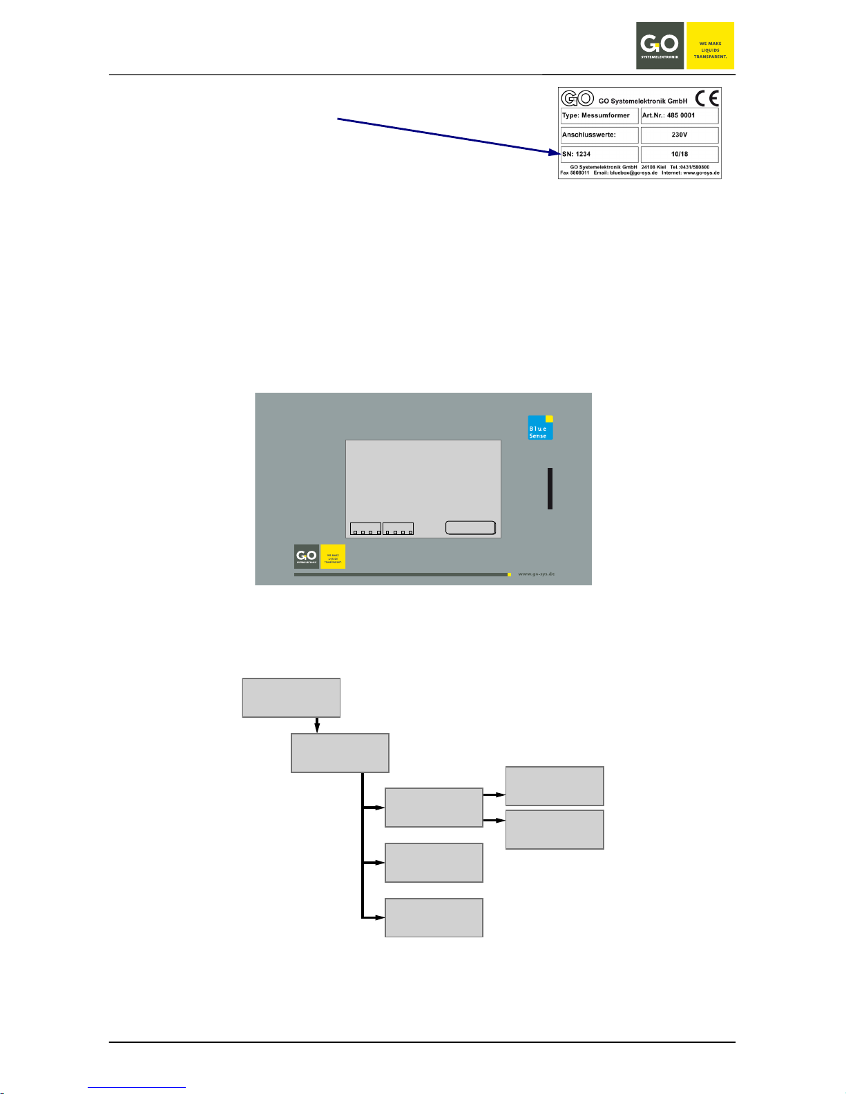
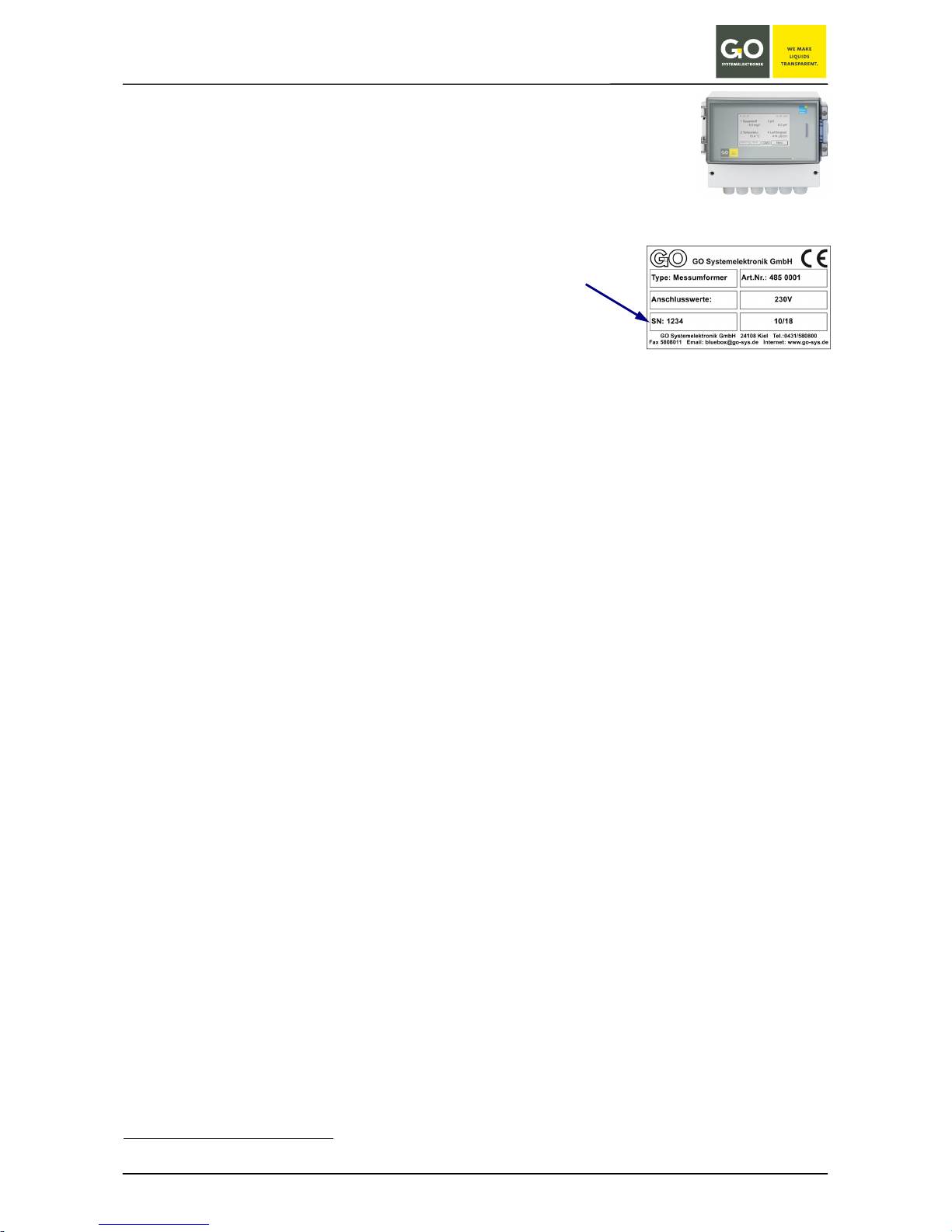
To determine if your Transducer has 1 or two 2 control parameters please
refer to the shipping note, the serial number of the transducer is on the
right hand side of the housing.
The transducer can store the states of the inputs (and therefore also the measured values) and the error messages on an SD Memory Card. The Transducer itself has no data storage.
The Transducer is operated via a touch screen. Through a few steps one can, for example, undertake calibrations and set switching values.
The menu options are displayed in simple to understand text.
Basic structure of the menu navigation:
see Appendix G – Menu Structure
1 Oxygen
8.0 mg/l
2 Temperature 1
18.4 °C
3 Conductivity
414 µS/cm
4 Temperature 2
19.0 °C
5 Salinity
5.4 ‰
6 Pulse 1
10 1/m
11 : 21 : 57 10 . 04 . 2013
Menu
Digital In
1
432
Relais
1
432
Parameter Display
Main Menu
Comport
Sensors
Setup
Memory Card
Programs
BlueSense
GO Systemelektronik GmbH Faluner Weg 1 24109 Kiel Germany Tel.: +49 431 58080-0 Fax: -58080-11
Page 8 / 58
www.go-sys.de info@go-sys.de
2 Technical Data and Connection Diagrams
2.1 Technical Data
Article-Nr. 485 0001-X
Inputs:
• 1 or 2 analogue inputs (1 Control parameter or 2 Control parameters)
The particular configuration is on the shipping note, the serial number
of the transducer is on the type plate at the right hand side
of the housing.
• 2 pulse inputs, selectable to PNP/NPN (also statically usable),
switching current approx. 6 mA, measurement range 0.05 Hz – 1000 Hz
• 2 digital inputs (static), potential-free contacts, switching current approx. 6 mA
Outputs:
• 2 current outputs (4 to 20 mA), active
• 2 relays with a low-voltage (only) switching capacity of 24 V / 0.5 A
• 2 relays with a switching capacity of 230 VAC / 2 A or 24 VDC / 6 A
Communications interfaces:
∗
• CAN-bus connector for connection to the BlueBox-System
or
• RS-232 or RS-485, each with 9600 Baud, Modbus
or
• Profibus
®
Voltage feed:*
• 12 VDC (9 – 18 VDC), received power max. 15 W
or
• 24 VDC (18 – 36 VDC), received power max. 15 W
or
• 230 VAC (90 – 260 VAC), received power max. 15 W
Display: LCD Touch Panel: 240 x 128 pixels; secure temperature range -10 to +45 °C
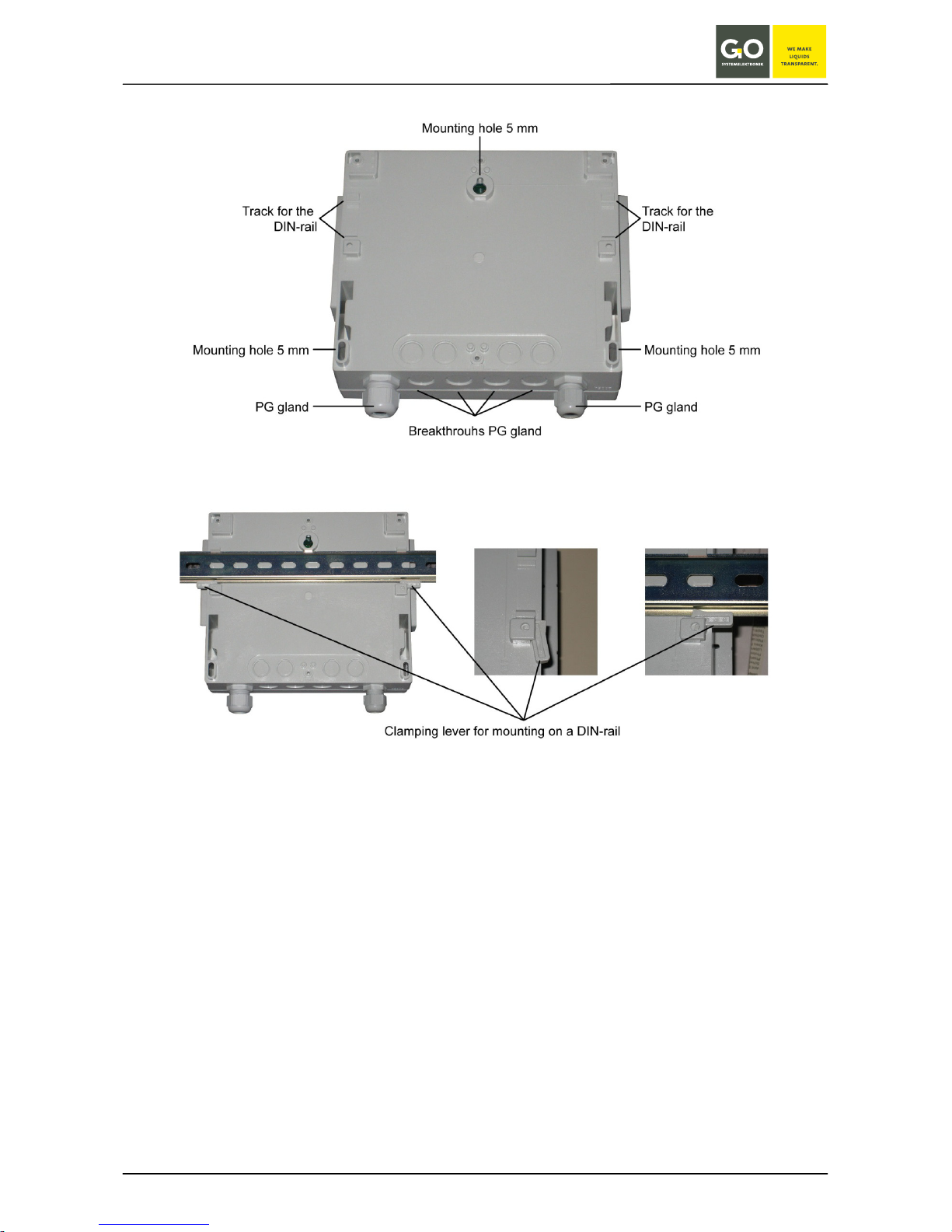
Housing: Polycarbonate, 235 mm x 185 mm x 119 mm; protection code IP65;
secure temperature range -10 to +45 °C
Weight: 1.35 kg
∗
The equipment of your transducer is documented on the sticker on the inside of the cover for the cable connections.
BlueSense
GO Systemelektronik GmbH Faluner Weg 1 24109 Kiel Germany Tel.: +49 431 58080-0 Fax: -58080-11
Page 9 / 58
www.go-sys.de info@go-sys.de
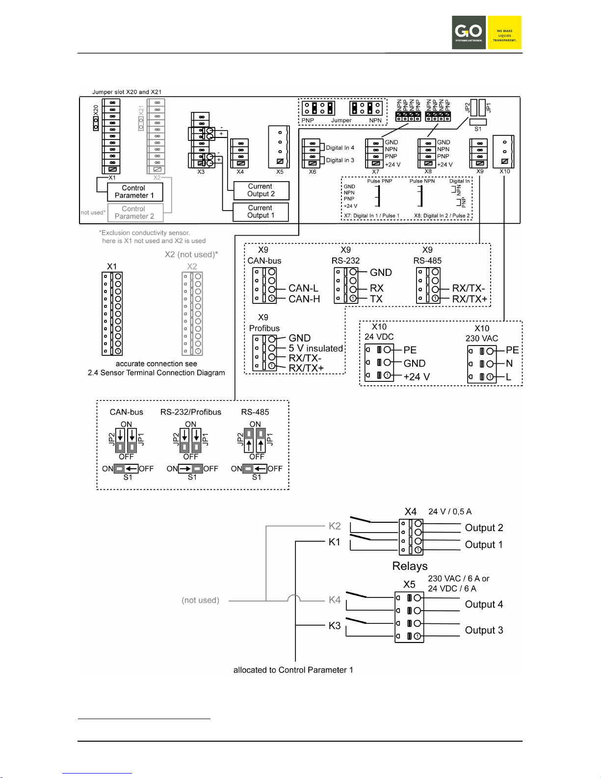
2.2 Connection Diagram 1 Control Parameter
∗
∗
Older devices have white switch sliders, for the correct slider positions, refer to the respective manual.
red switch sliders*
CAN-bus and RS-485:
S1 at ON
terminated
S1 at OFF not terminated
BlueSense
GO Systemelektronik GmbH Faluner Weg 1 24109 Kiel Germany Tel.: +49 431 58080-0 Fax: -58080-11
Page 10 / 58
www.go-sys.de info@go-sys.de
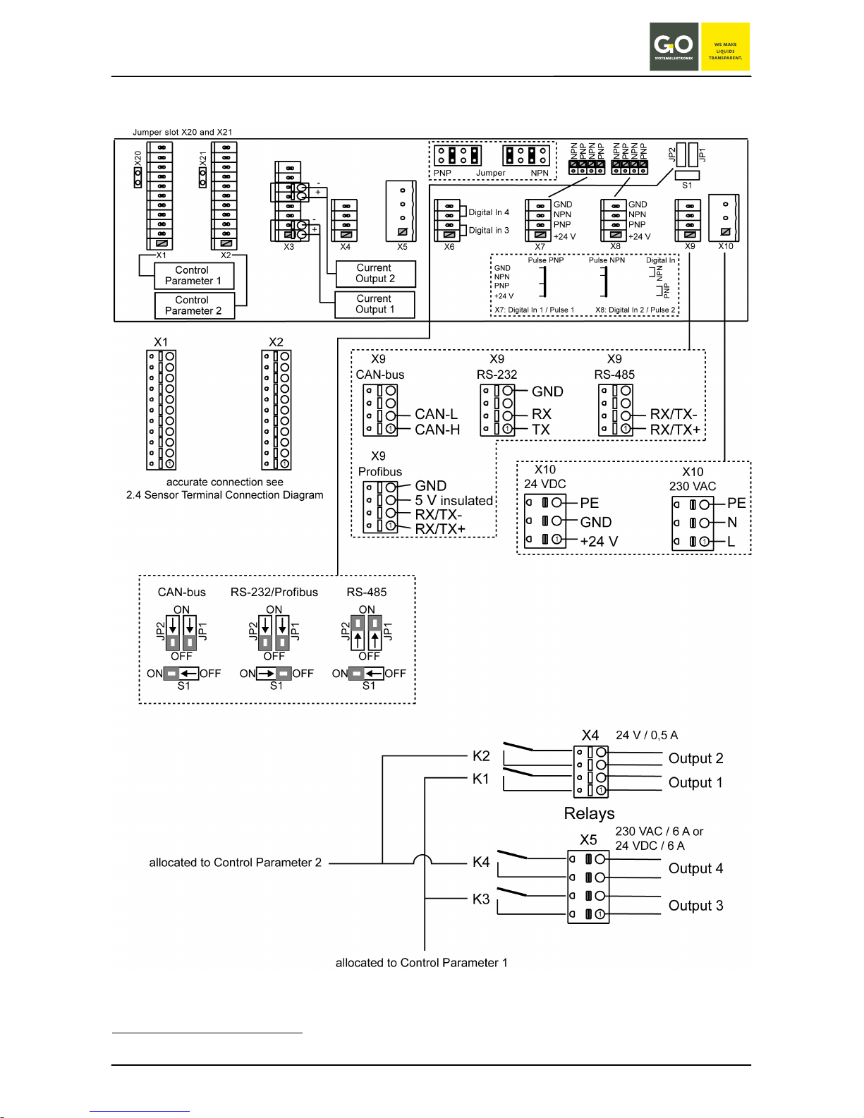
2.3 Connection Diagram 2 Control Parameter
∗
∗
Older devices have white switch sliders, for the correct slider positions, refer to the respective manual.
red switch sliders*
CAN-bus and RS-485:
S1 at ON terminated
S1 at OFF not terminated
BlueSense
GO Systemelektronik GmbH Faluner Weg 1 24109 Kiel Germany Tel.: +49 431 58080-0 Fax: -58080-11
Page 11 / 58
www.go-sys.de info@go-sys.de
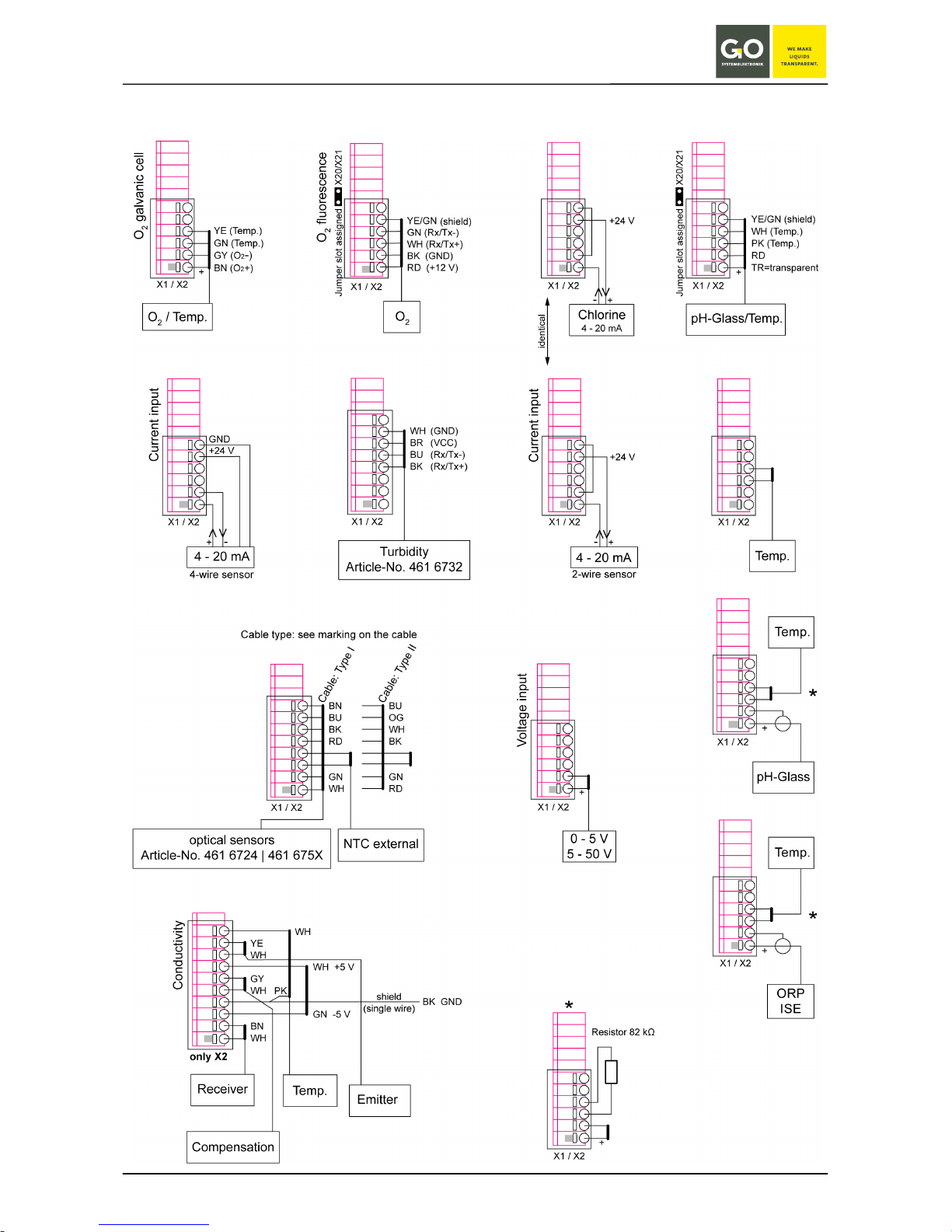
2.4 Sensor Terminal Connection Diagram
If no temperature sensor is connected here, the open input must
be closed with a resistor of approx.
82 kΩ.

BlueSense
GO Systemelektronik GmbH Faluner Weg 1 24109 Kiel Germany Tel.: +49 431 58080-0 Fax: -58080-11
Page 12 / 58
www.go-sys.de info@go-sys.de
2.5 Notes on the Pulse/Digital Inputs
The Blue Box T4 has 4 galvanically isolated digital inputs.
Pulse Inputs 1 and 2:
The assignment of the pulse inputs 1 and 2 is set at connector X7 and X8.
The pulse inputs 1 and 2 are provided for the connection of PNP or NPN encoders:
• The selection between PNP and NPN is set at the associated jumper slots.
• Assignment see 2.2 Connection Diagram 1 Control Parameter
or 2.3 Connection Diagram 2 Control Parameter
The two pulse inputs 1 and 2 can also be used as static inputs:
• Selection PNP: Signal at connection of 24 V and PNP
• Selection NPN: Signal at connection of GND and NPN
• Assignment see 2.2 Connection Diagram 1 Control Parameter
or 2.3 Connection Diagram 2 Control Parameter
Digital Inputs 3 and 4:
The digital inputs 3 and 4 are static inputs.
The assignment of the digital inputs 3 and 4 is set at connector X6.
• Digital input 3: Signal at connection of the two lower clamp sockets
• Digital input 4: signal at connecting the two upper clamping sockets
• Assignment see 2.2 Connection Diagram 1 Control Parameter
or 2.3 Connection Diagram 2 Control Parameter
At static use all 4 digital inputs are closers (NO = normally open).
2.6 Hazard Note
Danger: Improper handling of electrical devices endangers man and property.
Let carry out the commissioning of the BlueSense Transducer only by skilful, trained personnel
using appropriate tools. Incorrect installation could cause serious faults and errors that may
damage the device.
BlueSense
GO Systemelektronik GmbH Faluner Weg 1 24109 Kiel Germany Tel.: +49 431 58080-0 Fax: -58080-11
Page 13 / 58
www.go-sys.de info@go-sys.de
3 Commissioning
The Transducer’s respective sensors, supply voltage, current outputs and, where applicable, the relays, are to
be connected via the spring-loaded connectors. The terminals are marked.
see 2.2 Connection Diagram 1 Control Parameter or 2.3 Connection Diagram 2 Control Parameter
and 2.4 Sensor Terminal Connection Diagram
The cable entry is via the PG glands.
To-do list after initial start-up:
• language setting: see 5.4 Language setting
preadjustment: english
• time setting see 5.5 Time Date
preadjustment: timezone of the customer
• if applicable sensor calibration
e.g. for ISE sensors
• customer-specific settings
relay settings (switching and hysteresis values), current output settings, etc.
• if applicable adjustment of the touch display
The touch-panel is adjusted and ready for use. A long storage by the customer may cause the necessary of a new adjustment (see Appendix C – Adjustment of the Touch Display).
BlueSense
GO Systemelektronik GmbH Faluner Weg 1 24109 Kiel Germany Tel.: +49 431 58080-0 Fax: -58080-11
Page 14 / 58
www.go-sys.de info@go-sys.de
4 Turning On the System
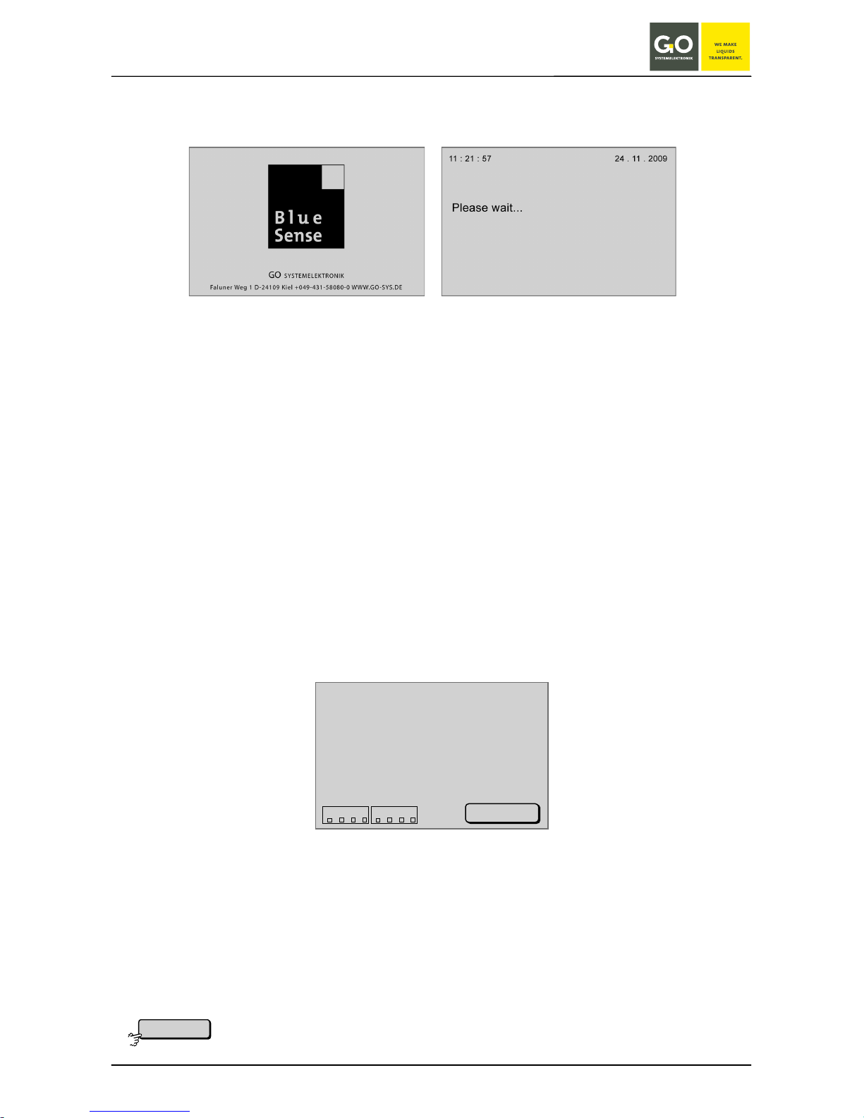
After the Transducer is switched on a software check and system initialisation occurs.
When the system is operational, the parameter display is activated.
4.1 Parameter Display and Main Menu
4.1.1 Parameter Display
The parameter display can show up to 6 different values.
Here, as an example, the measured parameter display with 6 displayed values.
• 1 Oxygen: the first control parameter oxygen
• 2 Temperature: the associated temperature parameter for the first control parameter
• 3 Conductivity : the second control parameter conductivity
• 4 Temperature: the associated temperature parameter for the second control parameter
• 5 Salinity: computed value from a conductivity measurement
• 6 Pulse 1: value of the first pulse input
The names of the sensors are automatically numbered and listed.
In top left-hand corner the time is displayed. In top right-hand corner the date is displayed.
In the lower left corner the states of the 4 Digital In inputs and the switching states of the 4 relays are displayed (see Sensor terminal connection diagram).
A filled square (
■) symbolizes the state 1, i.e. an input/relay is closed.
An empty square () symbolizes the state 0, i.e. an input/relay is open.
Status messages appear at the bottom of the parameter display (see Appendix E – Status and Error Messages).
When there is user inactivity in all other menus, the software switches in 2 minutes back to the Parameter
Display. Not valid for input menus.
1 Oxygen
8.0 mg/l
2 Temperature 1
18.4 °C
3 Conductivity
414 µS/cm
4 Temperature 2
19.0 °C
5 Salinity
5.4 ‰
6 Pulse 1
10 1/m
11 : 21 : 57 10 . 04 . 2013
Menu
Digital In
1
432
Relais
1
432
Switches to the Main Menu or, when the password protection is active, to a password
prompt. see 4.1.1.1 Password Prompt and 4.1.2 Main Menu
Menu
BlueSense
GO Systemelektronik GmbH Faluner Weg 1 24109 Kiel Germany Tel.: +49 431 58080-0 Fax: -58080-11
Page 15 / 58
www.go-sys.de info@go-sys.de
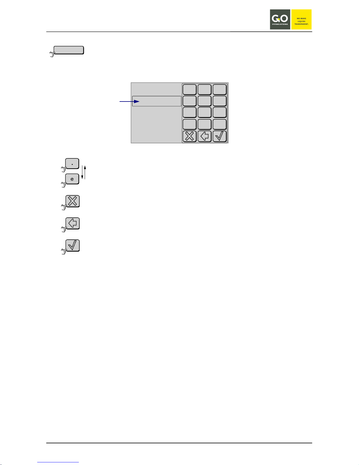
4.1.1.1 Password Prompt
Parameter Display
If the password protection is active, you have to enter a password here.
You activate and deactivate the password protection on the Main Menu, see next page.
See system password on the attached document.
Switches between the decimal notation “.” and the scientific notation “e” back
and forth,
when there is no entry in the input field.
The password is entered in the decimal notation.
Aborts the password prompt and switches back to the Parameter Display.
Deletes the last entered character.
Verifies the password and switches to the Main Menu.
If the password is incorrect, you receive an error message.
Menu
Password:
+/-
.
0
7
8
9
4
5
6
1
2
3
Input field
BlueSense
GO Systemelektronik GmbH Faluner Weg 1 24109 Kiel Germany Tel.: +49 431 58080-0 Fax: -58080-11
Page 16 / 58
www.go-sys.de info@go-sys.de
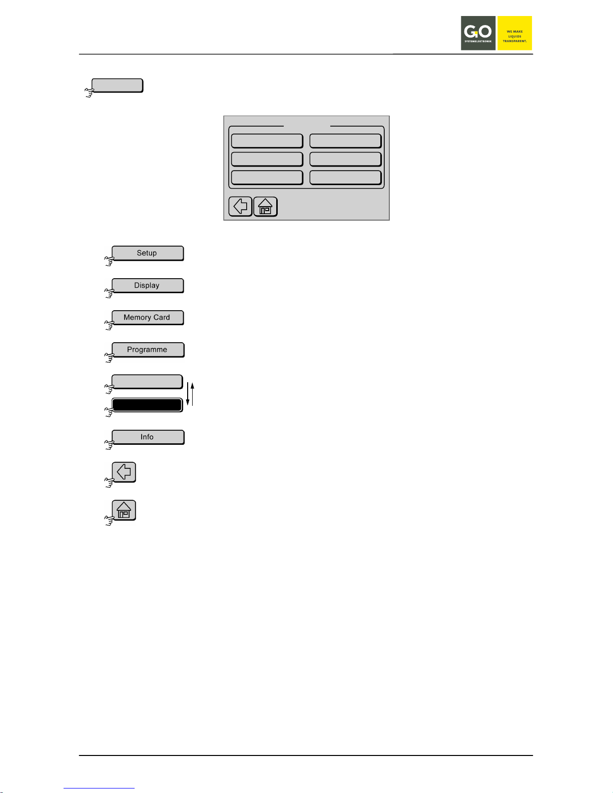
4.1.2 Main Menu
Parameter Display
Switches to the Setup menu, see 5 Setup.
Switches to the setting of the Display illumination, see 6 Screen.
Switches to the Memory Card menu, see 7 Memory Card.
Switches to the Program menu, see 8 Programs.
Switches the password protection of the menus active or inactive.
The button is also a status indicator.
Switches to the Info display of the transducer, see 9 Info Transducer.
Switches back to the Parameter Display.
Switches back to the Parameter Display.
Menu
Programs
Memory Card
Screen
Setup
Info
Main Menu
Menu Password
Menu Password
Menu Password
BlueSense
GO Systemelektronik GmbH Faluner Weg 1 24109 Kiel Germany Tel.: +49 431 58080-0 Fax: -58080-11
Page 17 / 58
www.go-sys.de info@go-sys.de
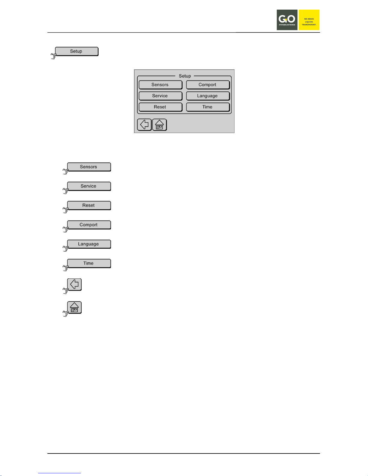
5 Setup
Main Menu
From this menu you can adjust the settings of the connected sensors and change system parameters.
Switches to the sensor menu, see 5.1 Sensors.
Switches to the password protected factory-presets. User changes are not necessary.
Switches to the Reset menu, see 5.2 Reset.
Switches to the Comport menu, see 5.3 Comport.
Switches to language setting menu, see 5.4 Language Setting.
Switches to the time and date entry menu, see 5.5 Time/Date.
Switches back to the Main Menu.
Switches to the Parameter Display.
BlueSense
GO Systemelektronik GmbH Faluner Weg 1 24109 Kiel Germany Tel.: +49 431 58080-0 Fax: -58080-11
Page 18 / 58
www.go-sys.de info@go-sys.de
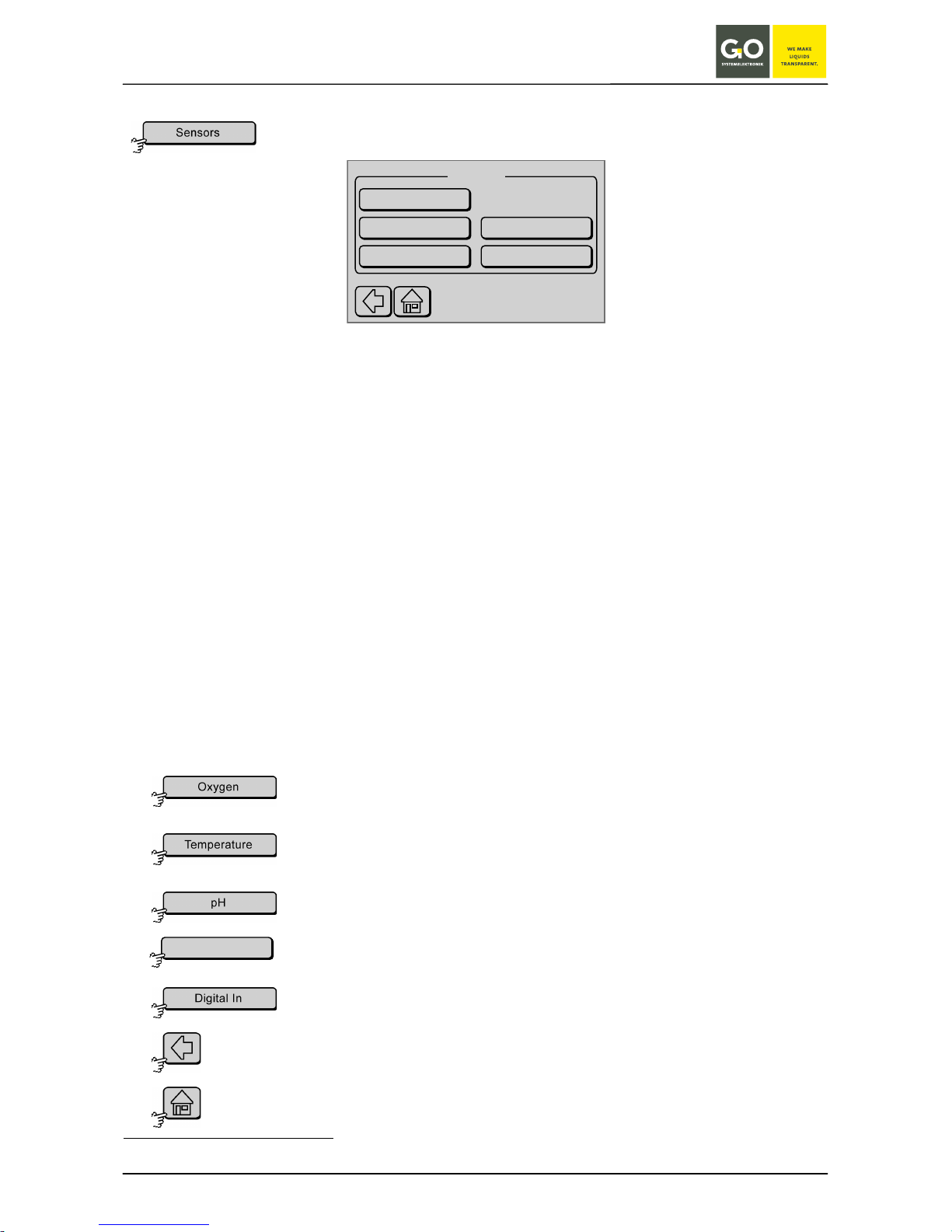
5.1 Sensors
Setup
From this menu you can set the parameters of the connected sensors.
The specific parameter setup is described in the sensor description.
The number of sensors that can be connected is determined by the delivered Transducer configuration. There
are two configurations:
• 1 Control parameter
One (1) sensor is connected. One control parameter is measured and where applicable the temperature as an associated parameter.
• 2 Control parameters
Two (2) sensors are connected. Two control parameters are measured and where applicable the
temperature for each sensor as associated parameters.
To determine if your transducer has one (1) or two (2) control parameters please refer to your shipping receipt.
This example has:
• 1. Sensor: Oxygen sensor (first control parameter)
• 2. Sensor: Oxygen sensor’s integrated Temperature sensor (associated parameter)
• 3. Sensor: pH sensor (second control parameter)
• 4. Sensor: Virtual sensor 1, which can calculate the salinity
∗
from a conductivity measurement
Switches to the Sensor Setup of the first sensor, in this case oxygen,
see 5.1.1 Oxygen Sensor Setup (Control Parameter).
Switches to menu of the second sensor, in this case temperature,
see 5.1.2 Temperature Sensor Setup (Associated Parameter).
Switches to the menu of the third sensor, in this case pH.
Switches to the menu of the virtual Sensor.
Settings as the temperature sensor
Switches to the information about the state of the digital inputs, see 5.1.3 Digital In.
Switches back to the Setup menu.
Switches to the Parameter Display.
∗
Salinity according to the general formula of the UNESCO for seawater
Oxygen
Temperature
pH
Sensors
virt. Sensor 1
Digital In
virt. Sensor 1
 Loading...