

Manual
BlueBox
DOC 486 0003-E-5.3-BDA
www.go-sys.de

BlueBox
© GO Systemelektronik GmbH
Copyright
This Manual contains information which is the intellectual property of GO Systemelektronik GmbH. The user
is obliged to use this information exclusively to run the instrument. It is not permitted to pass this information
to third parties. Reproducing, copying, editing or extracting the manual contents is only allowed with the express permission of GO Systemelektronik GmbH.
Changes
GO Systemelektronik GmbH retains the right to modify the contents of the manual without prior notice.
Liability Exclusion
GO Systemelektronik GmbH takes no responsibility for correct system operation under all possible operating
conditions. It is not possible to guarantee that the software will function completely without error under all
possible circumstances. GO Systemelektronik GmbH cannot therefore accept liability for direct or indirect
damage resulting from system operation or the contents of this manual.
Product Observance
Within the scope of our obligation for product observance GO Systemelektronik GmbH will endeavour to
warn third parties about all identified dangers which could arise from the interaction between hardware and
software and from the use of other components. Effective product observance is only possible with adequate information from the end user about the planned field of application and the hardware and software
used. If the conditions of use change or if the hardware or software are changed, due to the complex relationships between hardware and software it is no longer possible to describe all possible dangers and their
effects on the total system, in particular on our system. This manual does not describe every possible property and combination of the system. For further information, please contact GO Systemelektronik GmbH.
Manufacturer's declaration
In setting up the device it is important amongst other things to note the correct electrical connections, protection against connections to foreign bodies, humidity, protection against excessive moisture due to condensation and to the overheating of the device in proper and improper use.
The implementation of these measures is the responsibility of the installers who setup this device.
Faluner Weg 1
D- 24109 Kiel
Germany
Tel.: 0431/58080-0
Fax: 0431/58080-11
http://www.go-sys.d e
info@go-sys.de
GO Systemelektronik GmbH Faluner Weg 1 24109 Kiel Germany Tel.: +49(0)431-58080-0 Fax: -58080-11
www.go-sys.de info@go-sys.de
valid from firmware version: 2.76.11
file name: BDA_BlueBox_V5p3_en.pdf
Page 2 / 77

BlueBox
Table of contents
1 Properties and functions of the BlueBox .......................................................................................................................... 5
1.1 Essential properties of the system ............................................................................................................................. 5
1.2 Technical data ........................................................................................................................................................... 6
2 Before installation ............................................................................................................................................................. 7
2.1 Safety notices and warnings ...................................................................................................................................... 7
2.2 Basic equipment for operation ................................................................................................................................... 7
3 Installation ........................................................................................................................................................................ 8
3.1 Mounting of the BlueBox ........................................................................................................................................... 8
3.2 Connection options .................................................................................................................................................... 9
3.21 Connector pin assignment at the BlueBox ........................................................................................................ 10
3.3 Connecting of the power supply .............................................................................................................................. 11
3.4 LAN-connection ....................................................................................................................................................... 12
3.5 CAN-bus termination and RS-485 termination at the BlueBox ................................................................................ 13
3.6 Jumper position RS-232 or RS-485 ......................................................................................................................... 13
4 Connection of sensor and actuator modules .................................................................................................................. 14
4.1 Connection via M12 male plug ................................................................................................................................ 15
4.1.1 Mounting of the M12 male plug at the CAN-bus cable ..................................................................................... 15
4.2 Connection via spring clips ...................................................................................................................................... 16
4.3 Termination of the CAN-bus .................................................................................................................................... 17
4.4 Checking the Termination ....................................................................................................................................... 18
5 Connection of the CAN-bus repeater ............................................................................................................................. 19
6 The configuration data sheet .......................................................................................................................................... 20
7 Switching on the BlueBox and password input ............................................................................................................... 22
8 The menu operation ....................................................................................................................................................... 25
8.1 Parameter display ................................................................................................................................................... 25
8.1.1 Single parameter display .................................................................................................................................. 25
8.1.2 Multiple parameter display ............................................................................................................................... 26
8.2 Main menu ............................................................................................................................................................... 27
8.2.1 System menu ................................................................................................................................................... 28
8.2.1.1 Network Menu ........................................................................................................................................... 29
8.2.1.1.1 IP-Address menu ................................................................................................................................ 30
8.2.1.1.2 Netmask menu ................................................................................................................................... 31
8.2.1.1.3 Gateway IP-Address (default gateway) .............................................................................................. 32
8.2.1.1.4 Input timeserver .................................................................................................................................. 33
8.2.1.1.5 Internet settings .................................................................................................................................. 34
8.2.1.1.5.1 UDP settings ................................................................................................................................ 35
8.2.1.1.5.1.1 Setting IP address (UDP) ..................................................................................................... 36
8.2.1.1.5.1.2 Determine the password of the encryption ........................................................................... 37
8.2.1.1.5.2 Gateway settings (Internet) .......................................................................................................... 38
8.2.1.1.5.2.1 Input gateway settings (Internet) .......................................................................................... 39
8.2.1.1.5.3 DynDNS settings ......................................................................................................................... 40
8.2.1.1.5.3.1 Input DynDNS settings ......................................................................................................... 41
8.2.1.1.6 Info Network ....................................................................................................................................... 42
GO Systemelektronik GmbH Faluner Weg 1 24109 Kiel Germany Tel.: +49(0)431-58080-0 Fax: -58080-11
www.go-sys.de info@go-sys.de
Page 3 / 77

BlueBox
8.2.1.2 Time menu ................................................................................................................................................ 42
8.2.1.2.1 Date menu .......................................................................................................................................... 43
8.2.1.2.2 Time menu ......................................................................................................................................... 44
8.2.1.2.3
Time zone menu ................................................................................................................................. 45
8.2.1.2.4 Time drift menu .................................................................................................................................. 45
8.2.1.3 Shutdown .................................................................................................................................................. 46
8.2.1.4 Modem menu / Modem settings ................................................................................................................ 47
8.2.1.4.1 Modem port setup ............................................................................................................................... 48
8.2.1.4.2 Input of the PIN number .................................................................................................................... 49
8.2.1.4.3 Modem type settings .......................................................................................................................... 50
8.2.1.4.4 UMTS settings .................................................................................................................................... 51
8.2.1.4.4.1 Input UMTS settings .................................................................................................................... 52
8.2.1.4.5 Modem Info (UMTS) ........................................................................................................................... 52
8.2.1.5 GPS Menu ................................................................................................................................................. 53
8.2.1.5.1 GPS Port Setup .................................................................................................................................. 53
8.2.1.6 Display ....................................................................................................................................................... 54
8.2.1.7 Language settings ..................................................................................................................................... 55
8.2.2 Sensor list ........................................................................................................................................................ 56
8.2.3 Sensor menu .................................................................................................................................................... 57
8.2.3.1 Interval and Average ................................................................................................................................. 58
8.2.3.2 Calibration ................................................................................................................................................. 59
8.2.3.3 Table display (sensor values) .................................................................................................................... 60
8.2.3.4 Diagram display (sensor values) ............................................................................................................... 61
8.2.3.5 Sensor info ................................................................................................................................................ 62
8.2.3.6 Selection calibration mode ........................................................................................................................ 63
8.2.4 User variables .................................................................................................................................................. 64
8.2.5 Actuator list ...................................................................................................................................................... 65
8.2.5.1 Actuator menu ........................................................................................................................................... 66
8.2.5.1.1 Actuator setting .................................................................................................................................. 67
8.2.5.2 Diagram display (actuator) ........................................................................................................................ 68
8.2.5.3 Actuator info .............................................................................................................................................. 68
8.2.6 Help menu ........................................................................................................................................................ 69
8.2.6.1 Info menu of the system ............................................................................................................................ 69
8.2.6.2 Plug and clip connection ........................................................................................................................... 70
Appendix A - Adjustment of the touch display ................................................................................................................... 71
Appendix B - Calibrating a pH sensor ............................................................................................................................... 72
Appendix C - Calibration of an oxygen sensor .................................................................................................................. 73
Appendix D - Example configuration BlueGate-Server ..................................................................................................... 74
Appendix E - Update of the BlueBox firmware .................................................................................................................. 75
Appendix F - Opening a BlueBox housing ........................................................................................................................ 76
Appendix G - Status and error messages ......................................................................................................................... 77
GO Systemelektronik GmbH Faluner Weg 1 24109 Kiel Germany Tel.: +49(0)431-58080-0 Fax: -58080-11
www.go-sys.de info@go-sys.de
Page 4 / 77
BlueBox
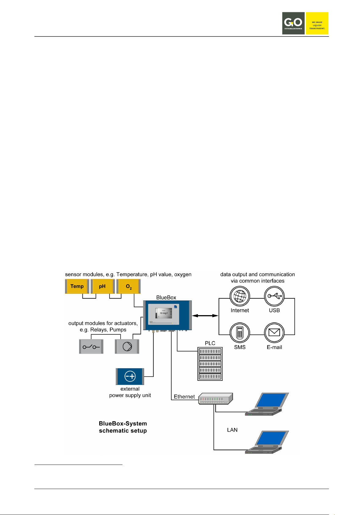
1 Properties and functions of the BlueBox
The BlueBox is the central element of the BlueBox-System. The BlueBox-System is a modular designed
measurement and control system.
The BlueBox is connected via CAN (Controller Area Network) technology with sensors and actuators.
For data processing and communication the BlueBox is equipped with the common interfaces.
1.1 Essential properties of the system
• Due to its modular structure the BlueBox system can handle almost every conceivable measurement
and control tasks.
• A BlueBox can be connected with up to 200 sensors or actuators. The connection takes place via sensor
1
modules
and actuator modules1 (output modules).
• In addition to sensors and actuators from our own product range, we also integrate products of almost all
other manufacturers.
2
• The sensor-actuator modules and can be used in bus or star ciruit configuration
decentralized over dis-
tances of up to 1000 meters (optionally longer).
3
• Measurement transfer and communication takes place via Ethernet, Internet, cellular radio
telephone line (ISDN, analogue), EMC or Modbus (RS-232 / RS-485), current outputs
(UMTS),
3
(4 – 20 mA).
• In mobile use it is possible to the connect the BlueBox with a GPS for the continuous position determi-
nation.
1
It is possible to connect multiple sensors/actuators to a sensor module.
2
A star circuit can only be used with a repeater (see 5 Connection of the CAN-bus repeater).
3
optional
GO Systemelektronik GmbH Faluner Weg 1 24109 Kiel Germany Tel.: +49(0)431-58080-0 Fax: -58080-11
www.go-sys.de info@go-sys.de
Page 5 / 77

BlueBox
1.2 Technical data
Computer: PC 104, 200 MHz to 500 MHz
Operation system Linux®
Random access memory 256 MB (optional 512 MB)
Display: Touchpanel 240x128 pixel
Storage media: Industrial Compact Flash Card 2 GB; 512 MB; 256 MB
Mechanical data: Housing dimensions: 280 mm x 170 mm x 90 mm (W x L x H)
Weight: approx. 2,6 kg
Protection class: IP 65
Die-cast aluminum housing, powder coated
Colour: RAL 5010
Power supply: Nominal voltage: 24 V DC (18 V – 28 V)
∗
Nominal power: 10 W,
additionally max. 1 A at the output to the modules
Interfaces: 1 x RS-232 or RS-485 (half-duplex)
1 x CAN
1 x Ethernet 10/100MBit
1 x USB
optional: 2 x current output 4 mA – 20 mA
Modem: optional: Modem UMTS
optional: Modem ISDN/analogue
Ambient conditions: Ambient temperature: Storage: -25 °C to +50 °C
Operation: -20 °C to +45 °C
avoid direct sunlight
Relative humidity ≤ 90 % (annual average)
To ensure equipment protection and the proper functioning of the device, the above conditions are strictly to
be adhered to!
∗
The connected modules receive their power from the BlueBox. Some modules have a constricted input range, so there
is a input voltage tolerance of ± 10%.
GO Systemelektronik GmbH Faluner Weg 1 24109 Kiel Germany Tel.: +49(0)431-58080-0 Fax: -58080-11
www.go-sys.de info@go-sys.de
Article-No. 486 0003
Page 6 / 77

BlueBox
2 Before installation
2.1 Safety notices and warnings
Please read the manual carefully before using the BlueBox. Keep this also within easy reach. Pass the
BlueBox never without the manual to other people. The manufacturer is not liable for improper use.
This unit is designed with Low Voltage Directive and the safety regulations for electronic devices.
The trouble-free operation and reliability can only be assured if you pay attention to the generally applicable
safety measures and special safety instructions in this manual .
• Before the connection of the Blue Box to the power supply make sure that the labeled BlueBox operating
voltage matches the supply voltage (indicating the areas of power supply).
• The correct functioning and operational safety of the device can only be ensured, if the ambient condi-
tions that are specified in the section 1.2 "Technical data" are complianced.
• If the device is transported from a cold to a warm environment condensation may result in a failure of the
function. In this case, wait until the device temperature is at the level of the ambient temperature before
a new start-up.
• Maintenance and repair work may only be performed by a specialist who is authorized by GO Systeme-
lektronik.
If you assume that the device can no longer be operated safely, it is taken out of service and avoid restarting.
The safety may be compromised by the device if, for example, the device:
• has visible damages,
• no longer works as required,
• has been stored in improper conditions for a longer time,
• was exposed to improper transport conditions.
In cases of doubt give notice to GO Systemelektronik GmbH . If necessary send the device to GO Systemelektronik for reparation respectively maintenance.
2.2 Basic equipment for operation
To operate the BlueBox in a meaningful way, a basic equipment is required:
1 x BlueBox
1 x CAN connection cable with a matching cable plug
1 x 24 V DC power supply unit with a connection cable to the BlueBox (43 W or 108 W)
1 x Sensor module or actuator module with connected sensor/actuator
GO Systemelektronik GmbH Faluner Weg 1 24109 Kiel Germany Tel.: +49(0)431-58080-0 Fax: -58080-11
www.go-sys.de info@go-sys.de
Page 7 / 77
BlueBox
1
2
3
4
3 Installation
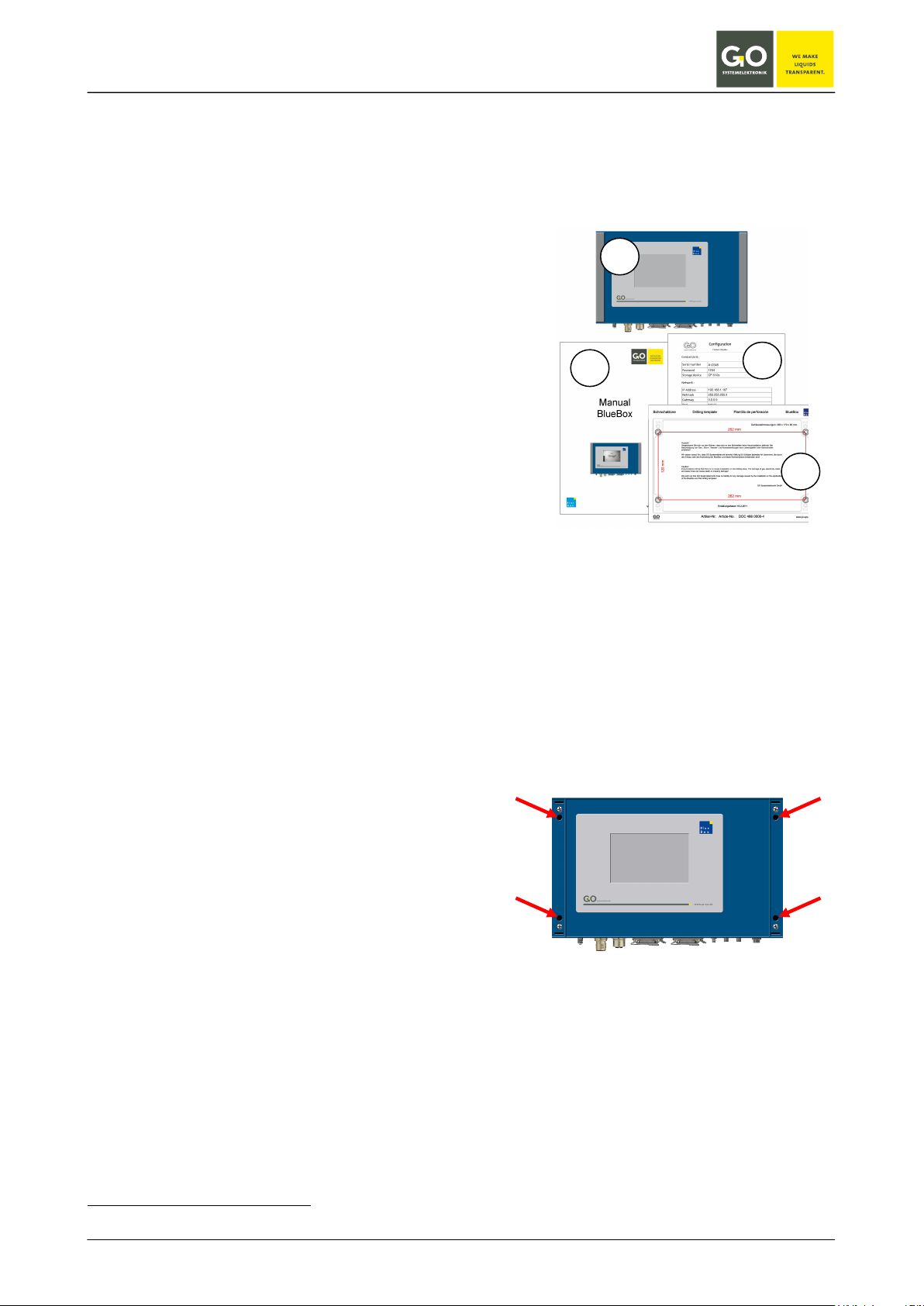
3.1 Mounting of the BlueBox
Before mounting the BlueBox check the scope of delivery for completeness:
(this is an example for a minimum delivery scope without power supply and without sensor-/actuatormodule)
1. BlueBox
2. Manual BlueBox
3. Configuration data sheet
4. Drilling template
Be careful when choosing the location of the BlueBox, the location has to achieve the following properties:
• rain-and sun-protected location
• convenient location for a mobile network coverage, if the Blue Box is used with an optional modem
The Blue Box should be mounted on a vertical surface.
The drilling template is used for mounting on a flat surface. Please choose suitable mounting screws and
dowels, which are suitable for the material of the mounting surface.
Remove the covers on both sides of the BlueBox.
Below you see the holes for the mounting screws.
Despite the construction of the BlueBox in protection class IP 65you have to install the measuring instrument
in a rain-and sun-protected site.
If this is not possible, the BlueBox must be mounted in an additional housing.
A great advantage of the BlueBox is their design flexibility. Therefore construction of installation will vary by
application. A description of the structure and assembly of the BlueBox can only serve as an example.
∗
∗
UMTS, ISDN, analogue
GO Systemelektronik GmbH Faluner Weg 1 24109 Kiel Germany Tel.: +49(0)431-58080-0 Fax: -58080-11
www.go-sys.de info@go-sys.de
Page 8 / 77
BlueBox
1 2 3
4 6 5
7 9 8
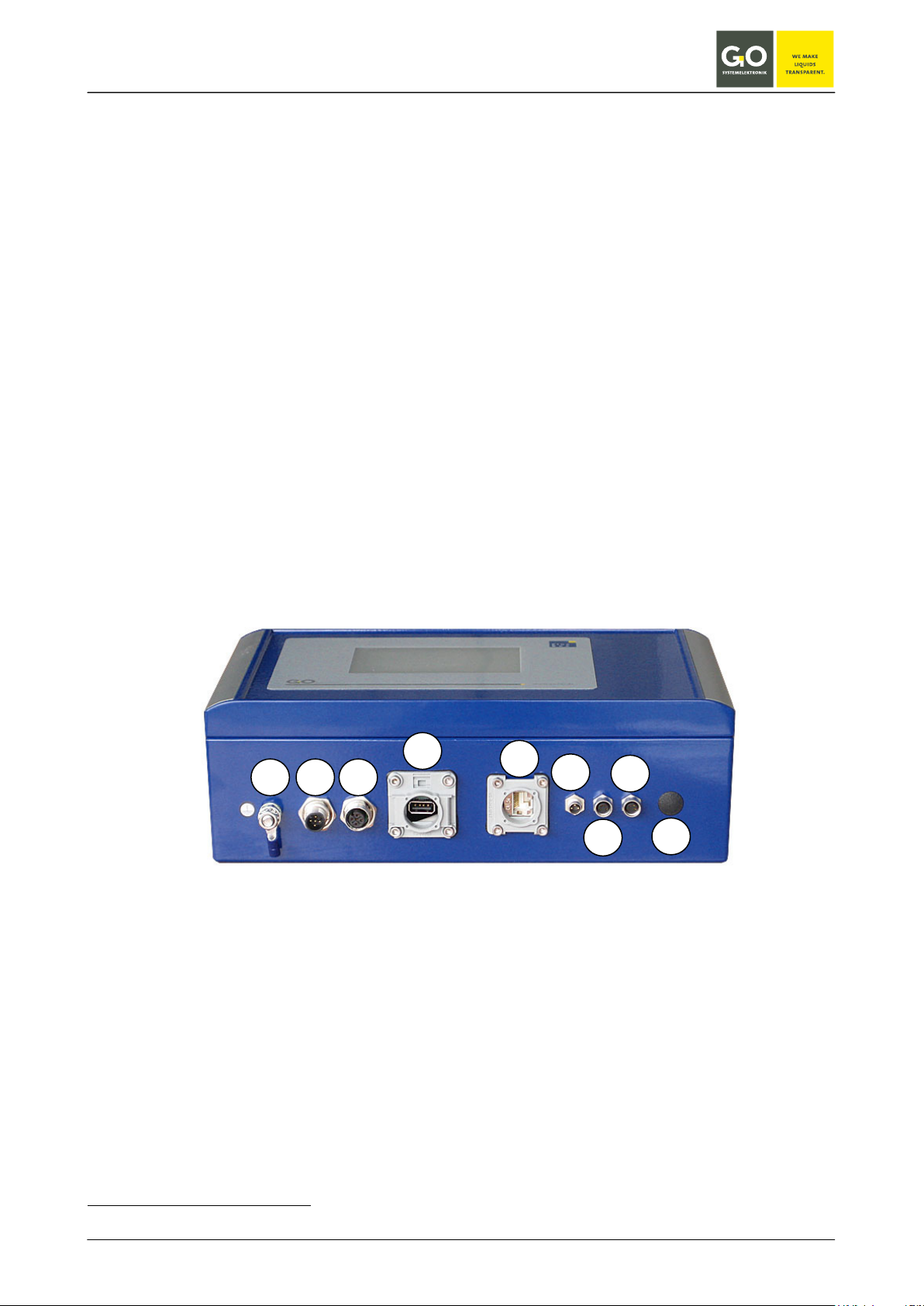
3.2 Connection options
The BlueBox has the following connection options:
1. Ground connection
2. Power supply (24 V DC) via a 5-pin M12 panel plug (male)
3. Connection CAN-bus via a 5-pin M12 panel jack (female)
CAN-bus connection to the BlueBox sensor-/actuator modules via 4-wire CAN-Bus connection cable
4. USB connection
Please note: The USB port on the BlueBox is provided for data storage and update the firmware.
5. LAN port for LAN cables in standard or cross-link design (see also 3.4).
6. Connection serial interface via a 3-pin M8 panel plug (male), RS-232 or RS-485
7. Connection current output
∗
4 to 20 mA via a 4-pin M8 panel jack (female)
8. Connection current output* 4 to 20 mA via a 4-pin M8 panel jack (female)
9. Hole for an antenna or cable modem
Modems (optional):
• UMTS modem with antenna
• analogue modem
• ISDN modem
∗
optional
GO Systemelektronik GmbH Faluner Weg 1 24109 Kiel Germany Tel.: +49(0)431-58080-0 Fax: -58080-11
www.go-sys.de info@go-sys.de
Page 9 / 77
BlueBox
Power supply 24 V DC
CAN-bus
4 GND 24 V
RS-232 or RS-485
4 TX RX/TX+
Current output 4 – 20 mA (optional)
1 2
1
4
3
2
1
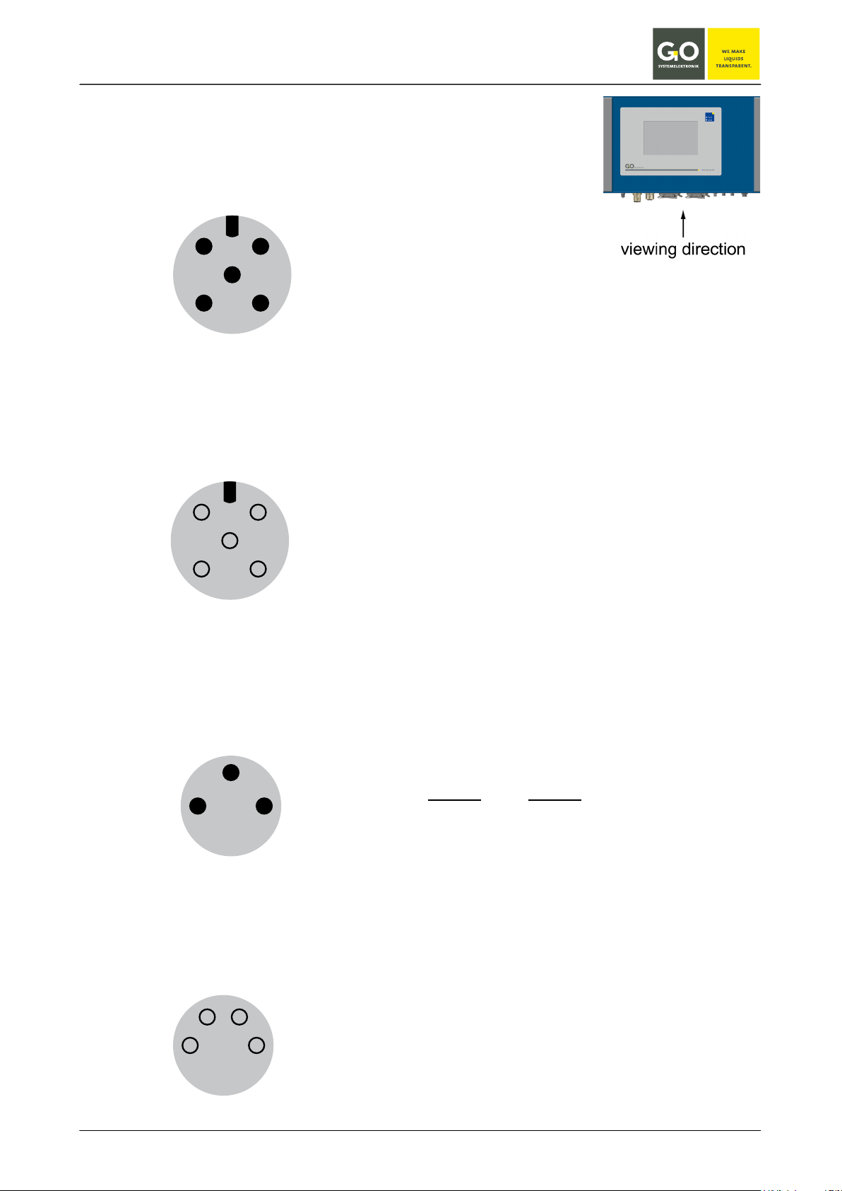
3.21 Connector pin assignment at the BlueBox
panel plug (M12, male)
3 +24 V DC
4 GND 24 V
43
panel jack (M12, female)
1 CAN-H
2 CAN-L
3 +24 V DC
34
panel plug (M8, male)
1 GND GND
3 RX RX/TX-
panel jack (M8, female)
1 +24 V DC
2 I-Return
RS-232
RS-485
GO Systemelektronik GmbH Faluner Weg 1 24109 Kiel Germany Tel.: +49(0)431-58080-0 Fax: -58080-11
www.go-sys.de info@go-sys.de
Page 10 / 77
BlueBox
24 V DC cable
220 V AC cable
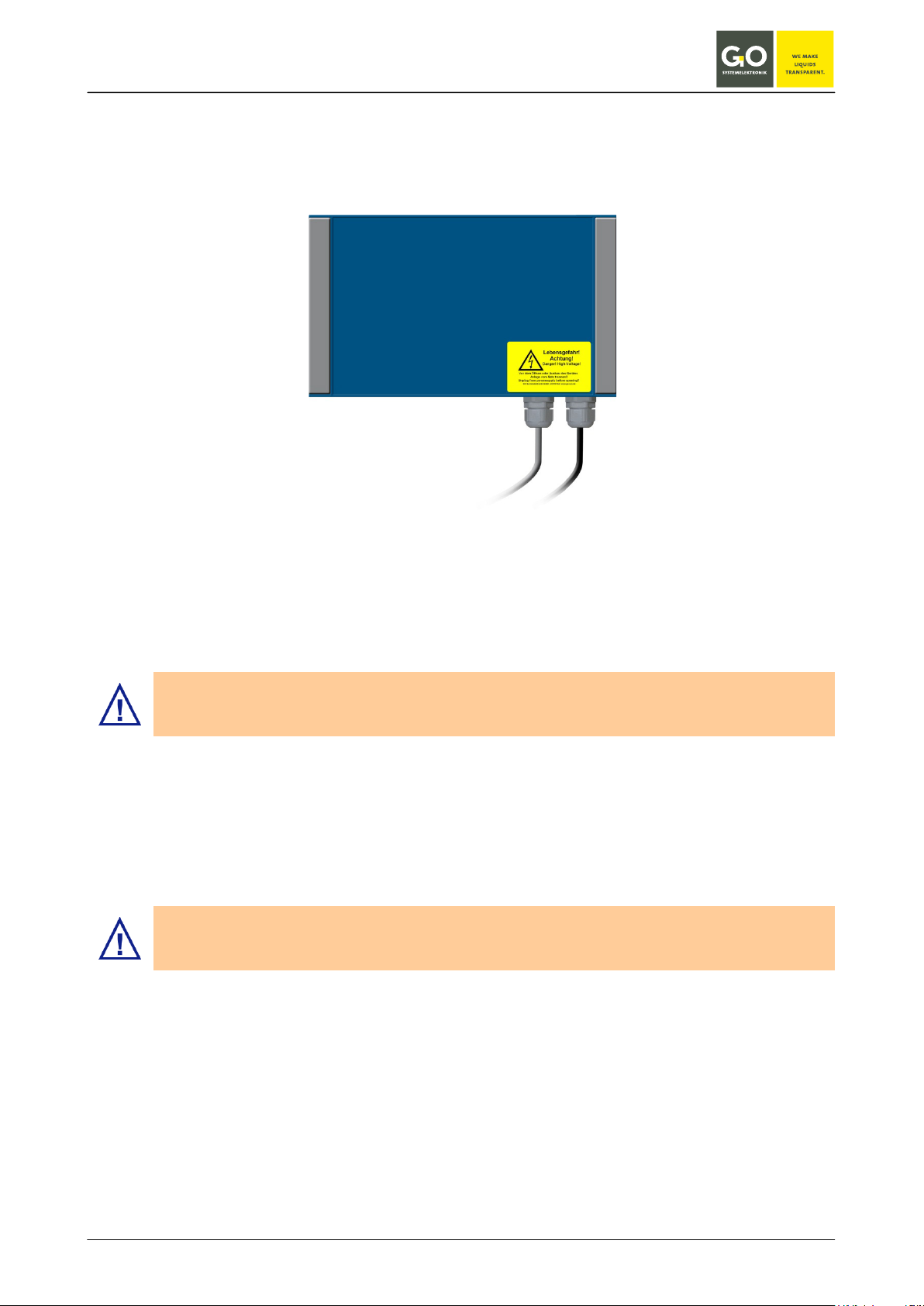
3.3 Connecting of the power supply
For connecting the power to the BlueBox you need an external power supply.
The power supply is available in two versions:
Power supply for the BlueBox (48 806 K00 00 A1), 43 W
Power supply for the BlueBox (48 806 K00 00 B1), 108 W
The BlueBox should only be installed by a qualified person using suitable tools. Incorrect installation can result in serious malfunction and could damage the instrument.
Compare the BlueBox data for voltage and frequency with the available supply before connecting the power.
Please notice that the power supply unit is placed close to the BlueBox because the voltage is declining with
the length of the connecting cable.
Please notice that it is necessary to use the appropriate conductor cable for the environment. In
the outside area it is advisable to use a rubber cable that is approved for the usage site.
The cable jack located on the 24 V DC cable is to stuck in an unambiguous way in the corresponding panel
plug of the BlueBox.
GO Systemelektronik GmbH Faluner Weg 1 24109 Kiel Germany Tel.: +49(0)431-58080-0 Fax: -58080-11
www.go-sys.de info@go-sys.de
Page 11 / 77
BlueBox
USB or LAN connector with protection class IP65 or higher.
3.4 LAN-connection
The LAN port allows the connection of the Blue Box to a Local Area Network or directly to a PC.
Thus, a retrieval of data and direct communication with the BlueBox is possible. This requires the installation
of the BlueBox PC software on your local computer (see Manual BlueBox PC Software).
The connection to a network is made by a RJ-45-connector at the bottom of the BlueBox (see also 3.2 Connection options).
For this connection you have to choose one of two different connecting cables.
• For connecting to a network you need a standard RJ-45 cable.
• For connecting to a PC you need a RJ-45-crosslink cable.
(Only if the PC has no automatic switch of the network interface.)
Please ensure that the RJ-45-plug snaps into the socket with a “click”!
If the closing cannot be inserted on the socket, please put vaseline on the rubber seal and try it again carefully.
Precondition for the protection class IP65:
• tightly twisted connector with protection class IP65 or higher on the
CAN-bus and power connection∗
• fitted caps on the USB and LAN connection
or
•
∗
The delivered plugs from GO Systemelektronik have the protection class IP65.
GO Systemelektronik GmbH Faluner Weg 1 24109 Kiel Germany Tel.: +49(0)431-58080-0 Fax: -58080-11
www.go-sys.de info@go-sys.de
Page 12 / 77
BlueBox
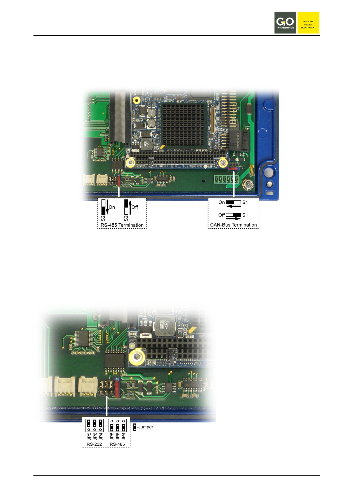
3.5 CAN-bus termination and RS-485 termination at the BlueBox
The CAN-bus termination is factory preset to ON.1
If you need to change the termination, open the housing
ON or OFF.
2
and set the respective termination switch to either
3.6 Jumper position RS-232 or RS-485
The BlueBox is factory preset to RS-232 unless requested otherwise by the customer.
If you need to change the jumper positions, open the housing and place the jumpers correspondingly.
1
If the BlueBox is configured to RS-485 by GO Systemelektronik, its termination is factory preset to ON.
2
see Appendix F - Opening a BlueBox housing
GO Systemelektronik GmbH Faluner Weg 1 24109 Kiel Germany Tel.: +49(0)431-58080-0 Fax: -58080-11
www.go-sys.de info@go-sys.de
Page 13 / 77
BlueBox
Error message: Socket Error # 10061/Connection refused)
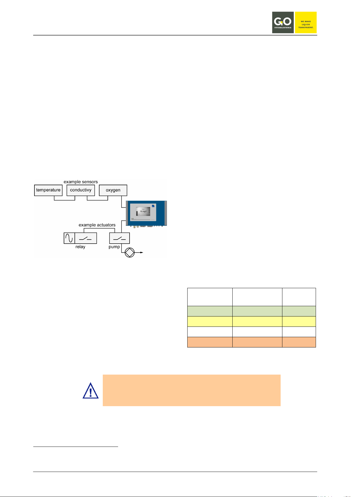
4 Connection of sensor and actuator modules
The connection of sensor- or actuator modules to
the BlueBox is made by CAN
Net-work). The connection at
the BlueBox is a M12-male-socket (see 3.2)
In the most cases the CAN-network is built as a
line-structure. At other structures the topology of
the network has to be conform to CAN-bus.
In a line structure the first and the last unit must
be terminated (see section 4.3 Termination of the
CAN-bus).
connection diagram sensors/actuators
∗
(Controller Area
BlueBox T2 and elder:
If no module is connected, the BlueBox is not detected from the
BlueBox PC software.
To connect a sensor-/actuator module with the
BlueBox insert the M12 male plug from the
CAN-connection cable into the M 12 female
socket at the BlueBox.
The other end of the CAN-connection cable can
be connected to a sensor-/actuator module in two
ways:
1. Connection with M12 male plug, see 4.1
Note the correct PIN assignment of the male plug
using the pin label.
When using a cable of the type LiYCY 2x2x0, 5
mm ² (article no. 339 0001), the color coding applies to the table below.
2. Connection with spring clips, see 4.2
Note the correct terminal connections using the
circuit board label.
When using a cable of the type LiYCY 2x2x0.5
mm² (article no. 339 0001), the color coding applies to the table below.
color coding cable type LiYCY 2x2x0.5 mm²
(article no. 339 0001)
PIN no.
Clip no.
color coding function
1 green (GN) CAN-High
2 yellow (YE) CAN-Low
3 white (WH) +24 V DC
4 brown (BN) 24 V GND
∗
The CAN-bus (Controller Area Network) is an asyn-
chronous serial bus system and belongs to the field bus.
GO Systemelektronik GmbH Faluner Weg 1 24109 Kiel Germany Tel.: +49(0)431-58080-0 Fax: -58080-11
www.go-sys.de info@go-sys.de
Page 14 / 77
BlueBox
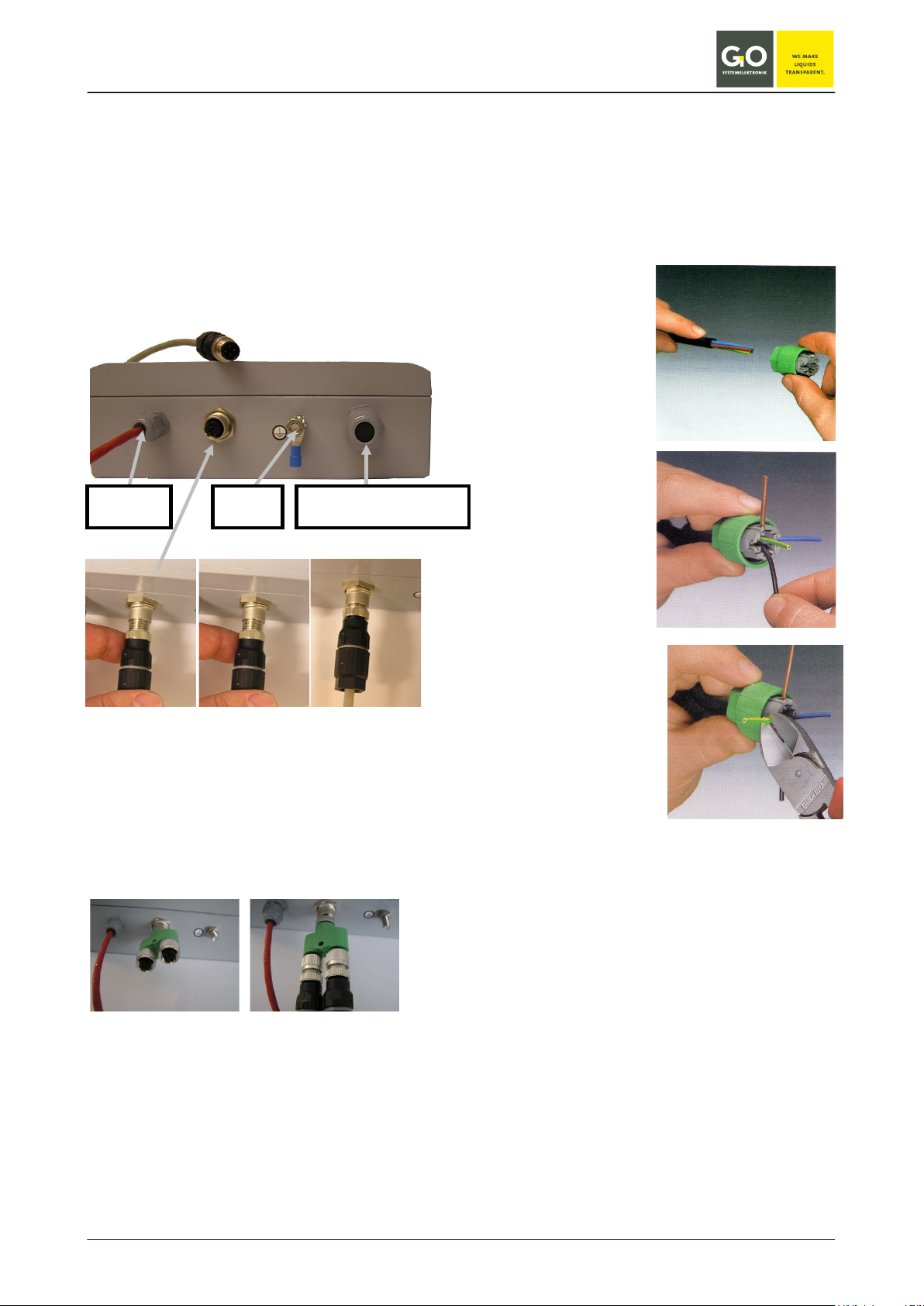
4.1 Connection via M12 male plug
As an example of connecting a sensor-/actuator
module using a 4-pin cable and two M12 connectors in the following the connection of a pH sensor
as a final module is shown. At the bottom of the
sensor housing is a four-pin M12 socket. In this
the four-pin M12 male plug off the CAN connection cable is inserted and fixed by turning the union nut.
pH sensor
earthing
sensor connection via M12-connector
(final module)
If the sensor module should be connected as a
pass module it is made by using a Y-splitter.
sensor connection via Y-splitter
(pass module)
optional sensor connection
4.1.1 Mounting of the M12 male plug at the CAN-bus cable
1. Remove the coating of the cable (approx. 40
mm)
2. Put the preassembled union nut
on the cable as far
as it will go.
3. Put the cable
strand in the
marked guidance
(configuration see
the table on the
previous page).
4. Cut off the overlaying end of the
cable strand.
exemplary connection of a M 12 plug
with a 4-PIN cable
CAN-bus connecting cables or connectors can be
ordered by us under the following article numbers.
Article no.:
Cable for data and supply 339 0001
M 12 male plug 338 1100
M 12 Y-splitter 338 1500
GO Systemelektronik GmbH Faluner Weg 1 24109 Kiel Germany Tel.: +49(0)431-58080-0 Fax: -58080-11
www.go-sys.de info@go-sys.de
Page 15 / 77
BlueBox
tion class IP 65.
1
2
3
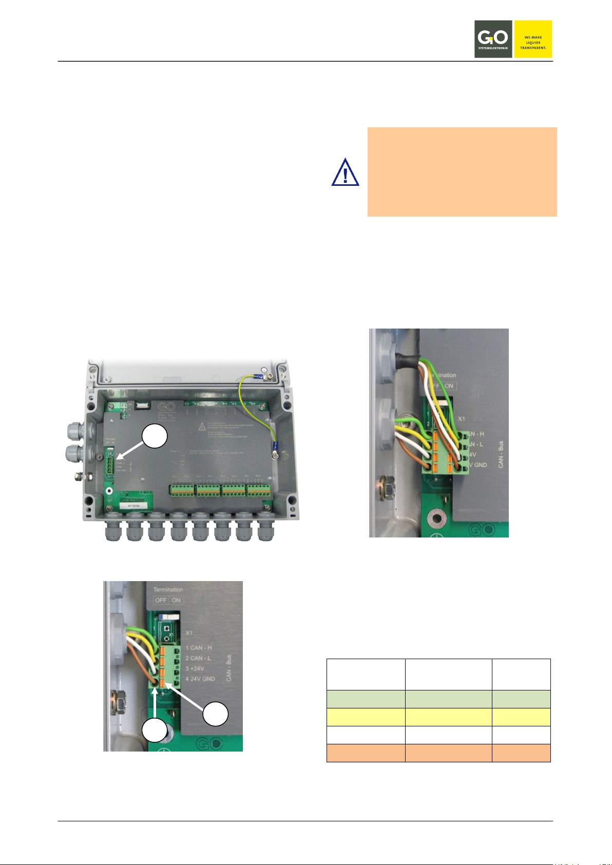
4.2 Connection via spring clips
The CAN-bus connecting cable will be brought
inside the housing through a grommet and connected to a socket connector that plugs into the
header of the CAN-bus connection (1).
The clamps are suitable for wire cross sections
between 0.5 and 2.5 mm². The cable has to be
isolated until a length of 9 or 10 mm. The cable
strand is put in the clamp how described in the
following:
Please push down the spring with a suitable
screw driver underneath the upper hole (3) in
which the cable bared will be insert (2).
Remove the screw driver from the spring.
The cable strand should be connected with the
clamp. Please check this by an easy traction at
the cable. If it is not, repeat the procedure.
If not all cable grommets in the housing are required, make sure that the
unused cable entries must be sealed
with plugs.
Only then the housing has the protec-
Below is shown how a sensor on the spring clip as
a pass module will be connected. In this case the
CAN-bus cable that goes to the next module has
to be connected with a row of the spring clip plug.
Please attend to the correct colour coding.
sensor connection with spring clips
(final module)
GO Systemelektronik GmbH Faluner Weg 1 24109 Kiel Germany Tel.: +49(0)431-58080-0 Fax: -58080-11
www.go-sys.de info@go-sys.de
sensor connection via spring clamps
(pass module)
color coding cable type LiYCY 2x2x0.5 mm²
(article no. 339 0001)
PIN no.
Clip no.
1 green (GN) CAN-High
2 yellow (YE) CAN-Low
3 white (WH) +24 V DC
4 brown (BN) 24 V GND
color coding function
Page 16 / 77
BlueBox
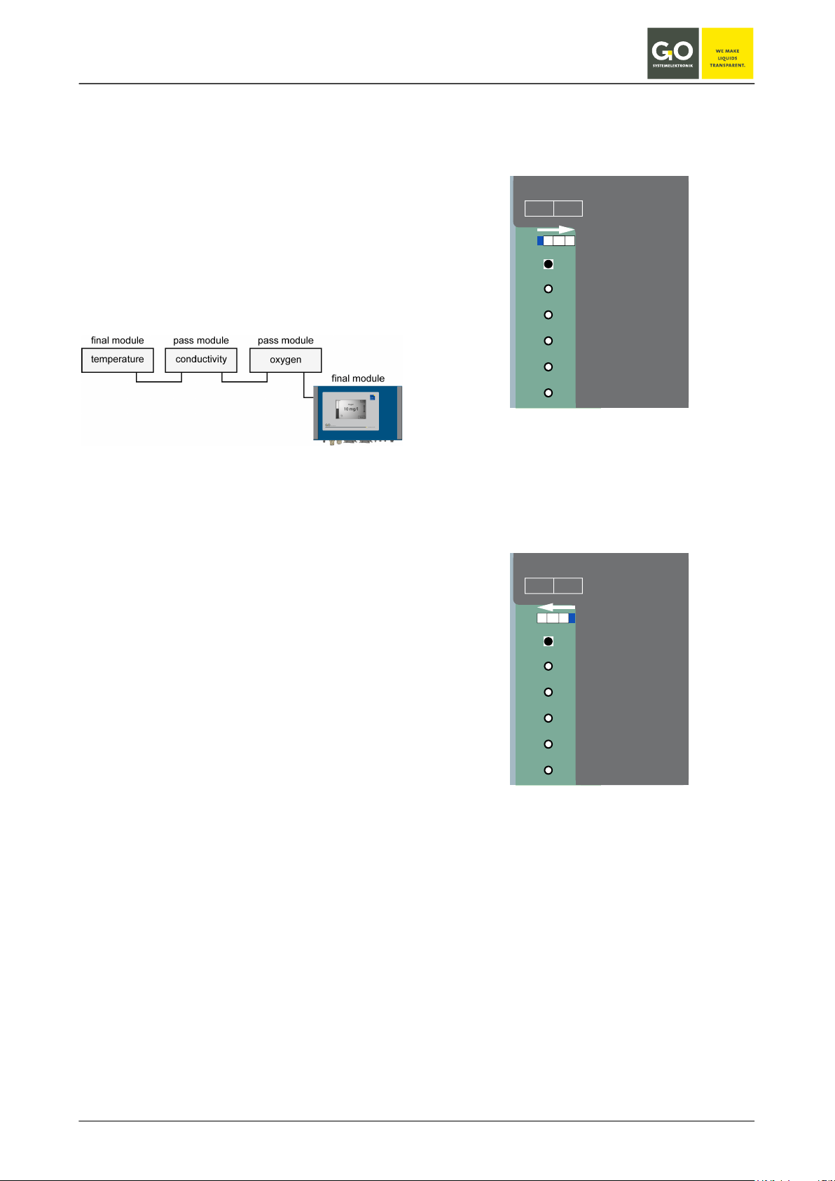
4.3 Termination of the CAN-bus
It is important to “terminate” the specific modules
in the right way. Physical this means, that a module at the beginning or the end of a bus has to be
endued with a closing resistor. With this “termination” the CAN-bus is closed, this prevents signal
Termination
OFF ON
reflections and signal interference.
Modules that are inside of a bus (pass modules)
may accordingly have no terminating resistor.
1
2
3
X1
X1
1 CAN - H
4
2 CAN - L
schematic representation of the CAN-bus line
structure, example
The on- and off-switching of the terminating resistor is done with a DIP switch. This DIP switch is
located in the module housing next to the connection clamps of the sensors and is labeled
"Termination".
The termination is switched on when the DIP
switch in position "ON".
The termination is switched off when the DIP
switch in position "OFF".
At the BlueBox itself, the termination resistor can
also be switched on and off. Here too, the DIP
switch is located next to the terminal to the cable
leading from the M12 connector on the motherboard. Because the BlueBox is in the majority of
installations at the beginning of the CAN-bus, the
BlueBox is terminated at the factory, i.e. the termination resistor is switched on.
If the Blue Box is in the middle of a CAN-bus, the
termination of the BlueBox must be switched off.
see:
3.5 CAN-bus termination and RS-485 termination
at the BlueBox
5
6
3 +24V
4 24V GND
CAN - Bus
DIP switch on position „ON“, the termination
resistor is switched on.
The device is a final module.
Termination
OFF ON
1
2
3
4
5
6
X1
X1
1 CAN - H
2 CAN - L
3 +24V
4 24V GND
CAN - Bus
DIP switch on position „OFF“, the termination
resistor is switched on.
The device is a pass module.
GO Systemelektronik GmbH Faluner Weg 1 24109 Kiel Germany Tel.: +49(0)431-58080-0 Fax: -58080-11
www.go-sys.de info@go-sys.de
Page 17 / 77
BlueBox
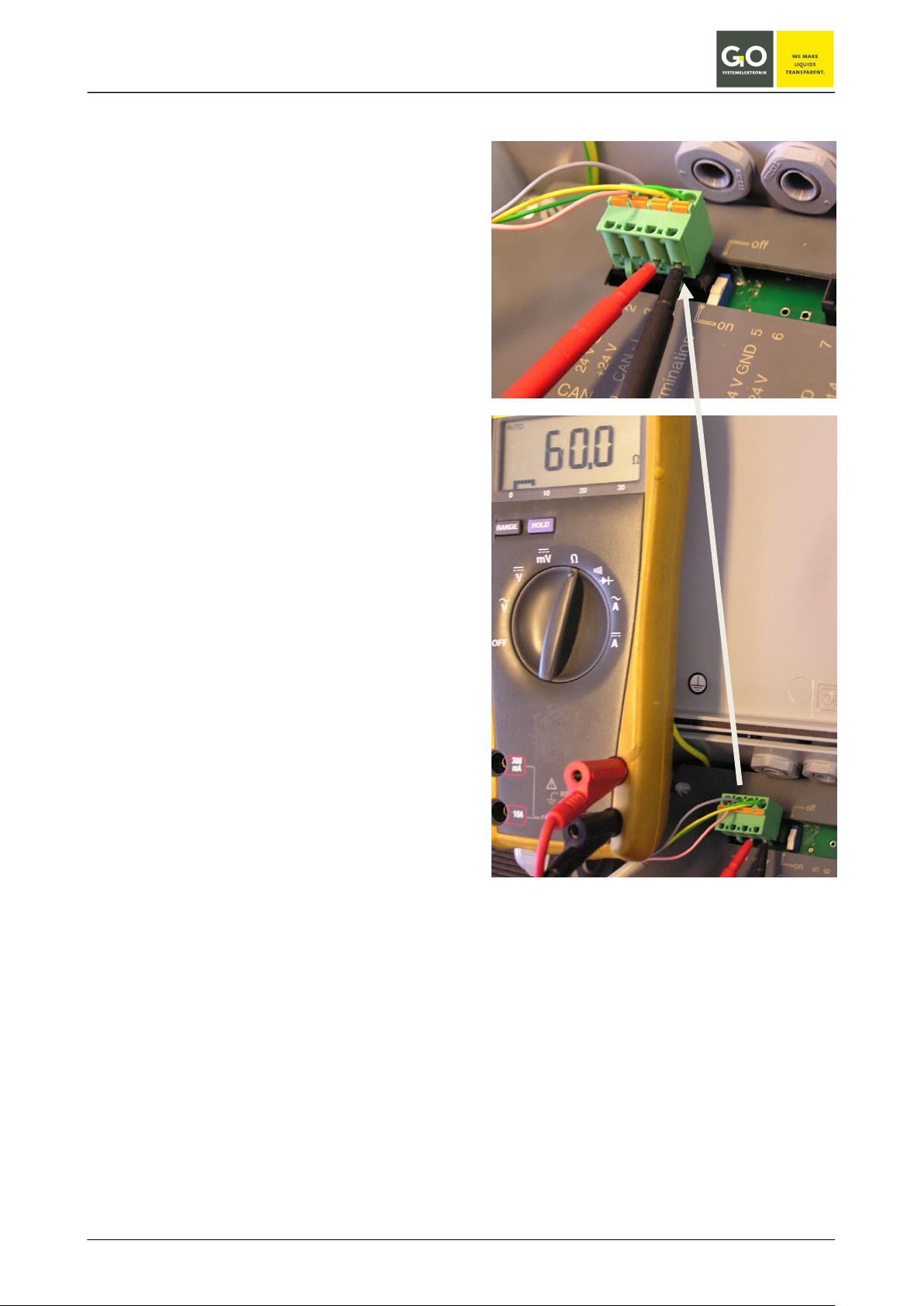
4.4 Checking the Termination
Please take notice of the correct termination of the
single modules to assure a correct performance of
the CAN-bus.
The termination can be controlled by measuring
the resistance between CAN-High and CAN-Low
with a multimeter.
The measurement can be done at any device of
the CAN-bus-system.
The easiest way to measure this resistance is
underneath the spring clips. That is the reason
why it is advisable to measure at modules with
clamps.
The measuring procedure is described in the following:
Consider that the modules that are going to be
proved are without voltage, i.e. the power supply
of the BLUEBOX has to be switched off.
Measure the resistance between CAN-High and
CAN-Low as it is shown in the illustration.
The measured value should be between 55 Ω
and 70 Ω. At the following divergency the respec-
tive errors are:.
0 Ω short circuit in line
< 55 Ω more than one module terminated
Korrekte Terminierung
120 Ω only one termination
(for example, only the BlueBox is
terminated)
>120 Ω no module is terminated or
cable break
GO Systemelektronik GmbH Faluner Weg 1 24109 Kiel Germany Tel.: +49(0)431-58080-0 Fax: -58080-11
www.go-sys.de info@go-sys.de
Page 18 / 77
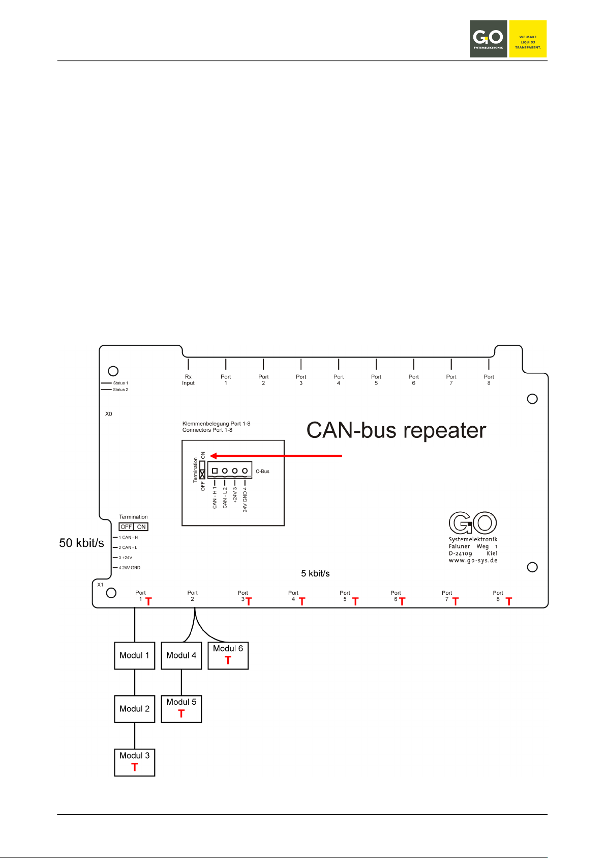
BlueBox
T: Termination with DIP switch
5 Connection of the CAN-bus repeater
(article no. 486 R000)
The active CAN repeater is a module to enlarge the CAN-bus topology. A repeater provides eight galvanic
disconnected bus segments.
Each of this bus segments can connect up to five modules on a max. length of 1000 m. The individual bus
segments are to be provided as necessary with a separate power supply.
The connection is carried out by circuit board connectors. The transfer rate is adjusted by the factory to a
value between 5 kBit/s and 50 kBit/s.
In case of long cable lengths or security applications the use of an active CAN repeater is inadvisable.
The figure below shows which connections of the CAN-bus inside the CAN repeater have to be terminated.
The figure can only be seen as an example.
DIP switch at "ON"
GO Systemelektronik GmbH Faluner Weg 1 24109 Kiel Germany Tel.: +49(0)431-58080-0 Fax: -58080-11
www.go-sys.de info@go-sys.de
Page 19 / 77
BlueBox
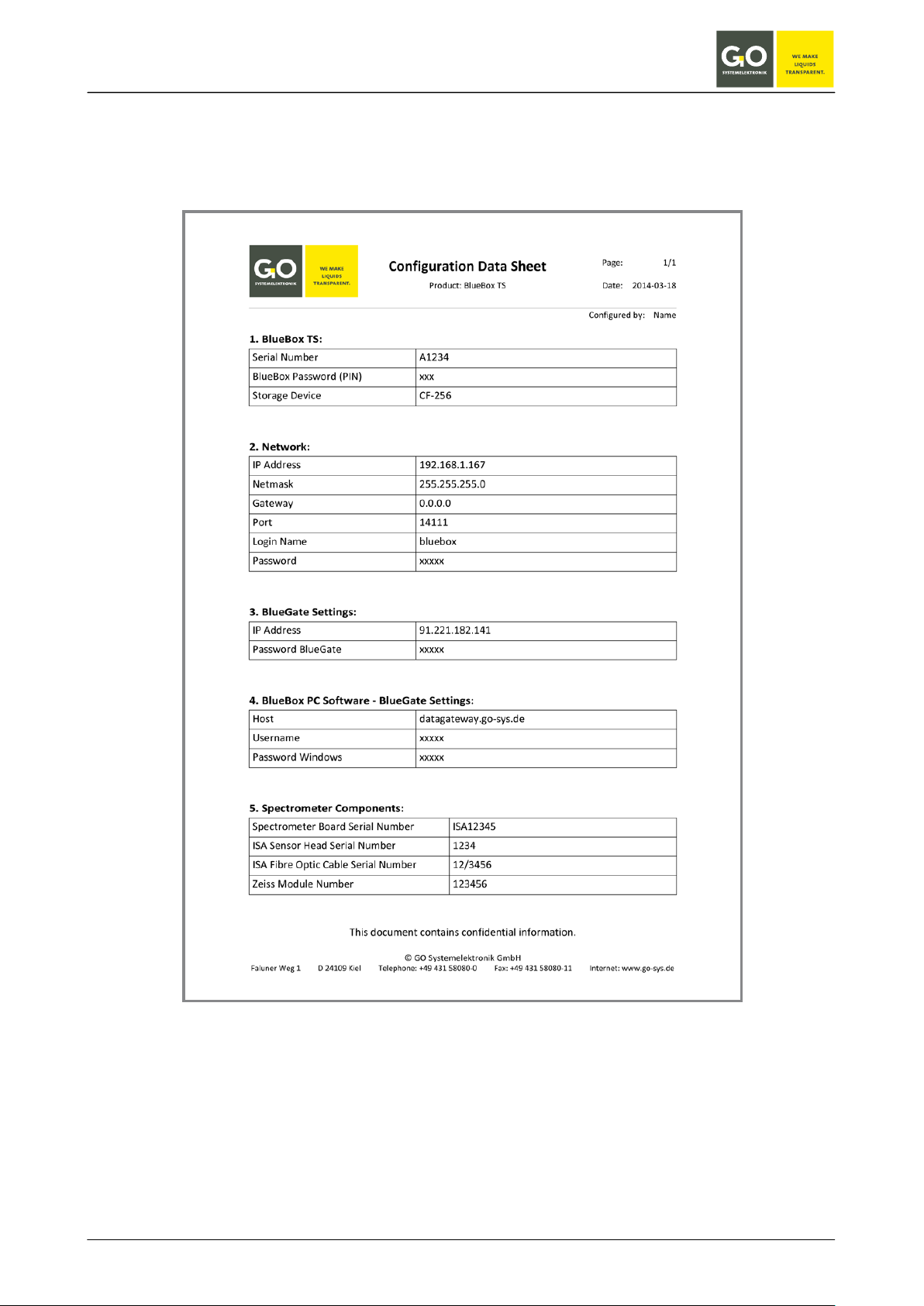
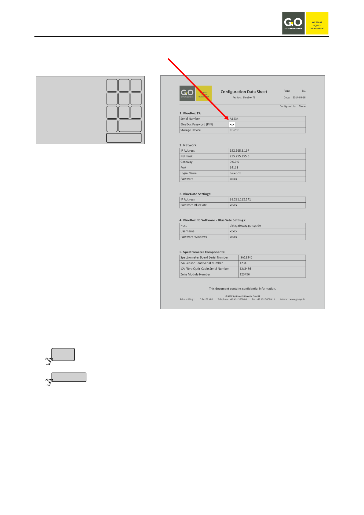
6 The configuration data sheet
The configuration data sheet contains the necessary settings to run the BlueBox.
Example BlueBox TS:
GO Systemelektronik GmbH Faluner Weg 1 24109 Kiel Germany Tel.: +49(0)431-58080-0 Fax: -58080-11
www.go-sys.de info@go-sys.de
Page 20 / 77
BlueBox
1. BlueBox TS:
Serial Number A1234
BlueBox Password (PIN) xxxxx
Storage Device CF-256
Serial Number Serial number of the BlueBox
With this serial number the BlueBox is identified by the
BlueBox PC Software.
set at the factory, not changeable
BlueBox Password (PIN) Password of the BlueBox
Is required to change the BlueBox system settings.
set at the factory, not changeable
Storage Device Model and size of the internal memory of the BlueBox, here CF-256
(CF = Compact Flash, 256 = 256 MB)
set at the factory, changeable by replacing
2. Network:
IP Address 192.168.1.167
Netmask 255.255.255.0
Gateway 0.0.0.0
Port 14111
Login Name bluebox
Password xxxxx
IP Address IP address of the BlueBox
At this address, the BlueBox is addressed on the network.
set at the factory, changeable
Netmask Netmask of the BlueBox
set at the factory, changeable
Gateway Default gateway of the Blue Box
set at the factory, changeable
Port Network Port of the BlueBox
set at the factory1, not changeable
Login Name User name for a modem connection
set at the factory, not changeable
see Manual BlueBox PC Software,
3.2.3 RAS setup
Password Network password of the BlueBox
Is needed to access the BlueBox via the AMS software.
set at the factory, not changeable
1
14111 / or when encryption is enabled 14110
GO Systemelektronik GmbH Faluner Weg 1 24109 Kiel Germany Tel.: +49(0)431-58080-0 Fax: -58080-11
www.go-sys.de info@go-sys.de
Page 21 / 77
BlueBox
3. BlueGate Settings:
IP Address
91.221.182.1411
Password BlueGate xxxxx
IP Address IP address of an Internet Gateway
can be configured at the factory, changeable
Password BlueGate Password of an Internet Gateway
can be configured at the factory, changeable2
4. BlueBox PC Software - BlueGate Settings:
Host datagateway.go-sys.de
Username bluebox
Password Windows xxxxx
If the BlueBox is accessed via a gateway (e.g. a UMTS connection), you have to enter these access
data in the BlueBox SQL Software (see Manual BlueBox PC Software, 3.2.2 Setup of a new BlueBox).
only BlueBox TS
5. Spectrometer Components:
Spectrometer BoardSerial Number ISA12345
ISA Sensor Head Serial Number 1234
Fibre Optic Cable Serial Number 12/3456
Zeiss Module Number 123456
ISA Spectrometer Board Serial Number Serial number of the spectrometer board
set at the factory, not changeable
ISA Sensor Head Serial Number Serial number of the sensor head
set at the factory, not changeable
Fibre Optic Cable Serial Number Serial number of the sensor head cable
set at the factory, not changeable
Zeiss Module Number Serial number of the Zeiss spectrometer module
set at the factory, not changeable
1
IP-Address of the GO webserver (default address)
2
changeable only at the default address
GO Systemelektronik GmbH Faluner Weg 1 24109 Kiel Germany Tel.: +49(0)431-58080-0 Fax: -58080-11
www.go-sys.de info@go-sys.de
Page 22 / 77
BlueBox
GO
SY STEMELEKTRONIK
Faluner Weg 1 D-24109 Kiel +049-431-58080-0 WWW.G O-SYS.DE
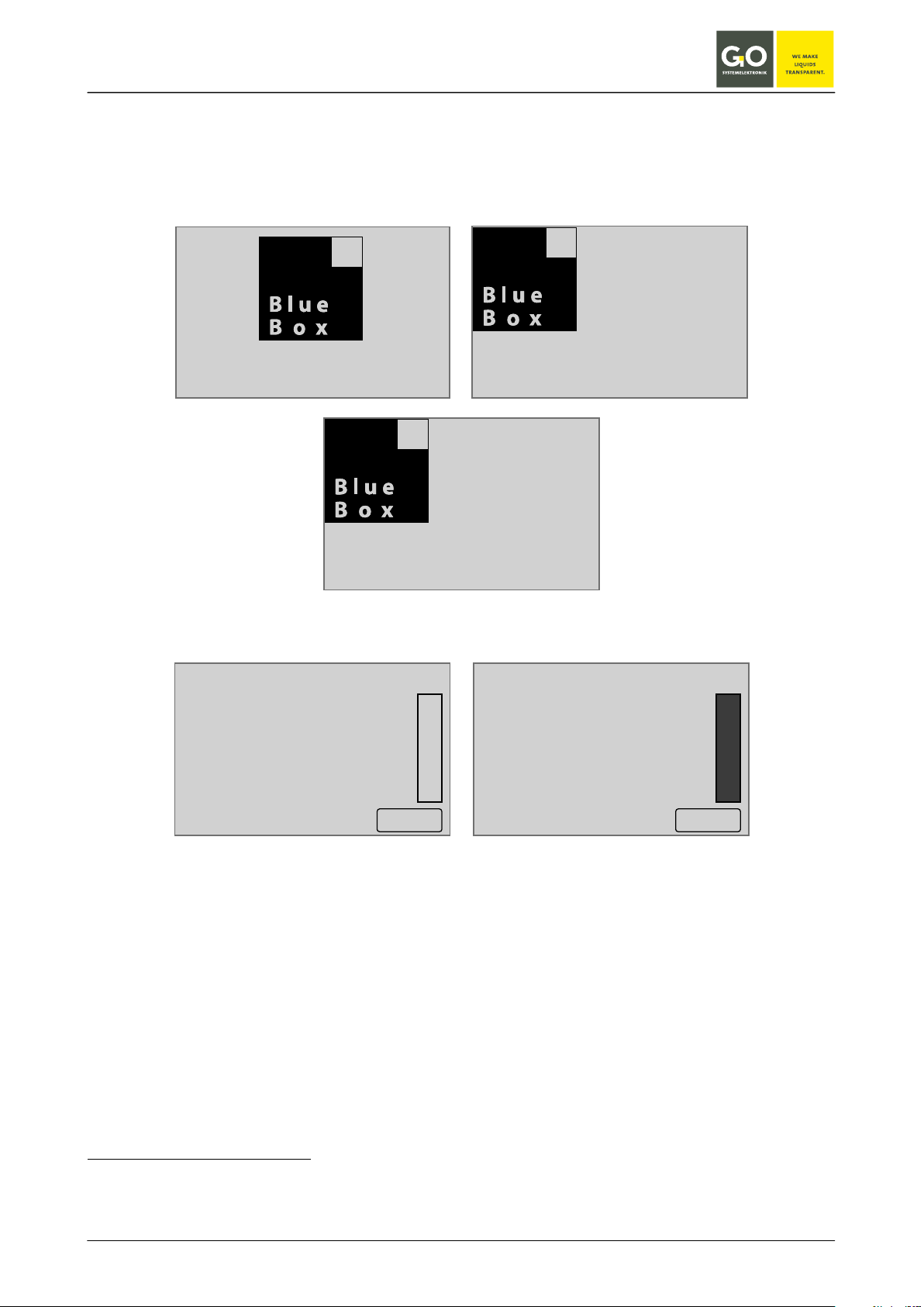
7 Switching on the BlueBox and password input
After the Blue Box has been started by switching on the power supply, shortly thereafter on the display1 appear in succession the following notes.
During this time the BlueBox checks the database and initiates the system.
Check
Filesystem
Init
System
Then the BlueBox initiates the connected sensors and actuators.
Boot Info
Search
Sen sors 3 / 3
Akt uators 0 / 0
Vi rtual Sen sors 1 / 1
09:19:39
10.07.10
Menu
Boot Info
Read y
Sen sors 3 / 3
Akt uators 0 / 0
Vi rtual Sen sors 1 / 1
09:19:39
10.07.10
Ok
Once the initialization is complete, the display shows the number of connected sensors, actuators and virtual
2
sensors
. After 20 seconds or after pressing > OK < the Parameter display (8.1) appears.
1
At delivery the touch panel is calibrated and ready for use. After a longer storage it may be necessary to adjust for the
touch panel (see Appendix A).
2
The setup of virtual sensors is done with the AMS software, see manual BlueBox PC Software.
GO Systemelektronik GmbH Faluner Weg 1 24109 Kiel Germany Tel.: +49(0)431-58080-0 Fax: -58080-11
www.go-sys.de info@go-sys.de
Page 23 / 77
BlueBox
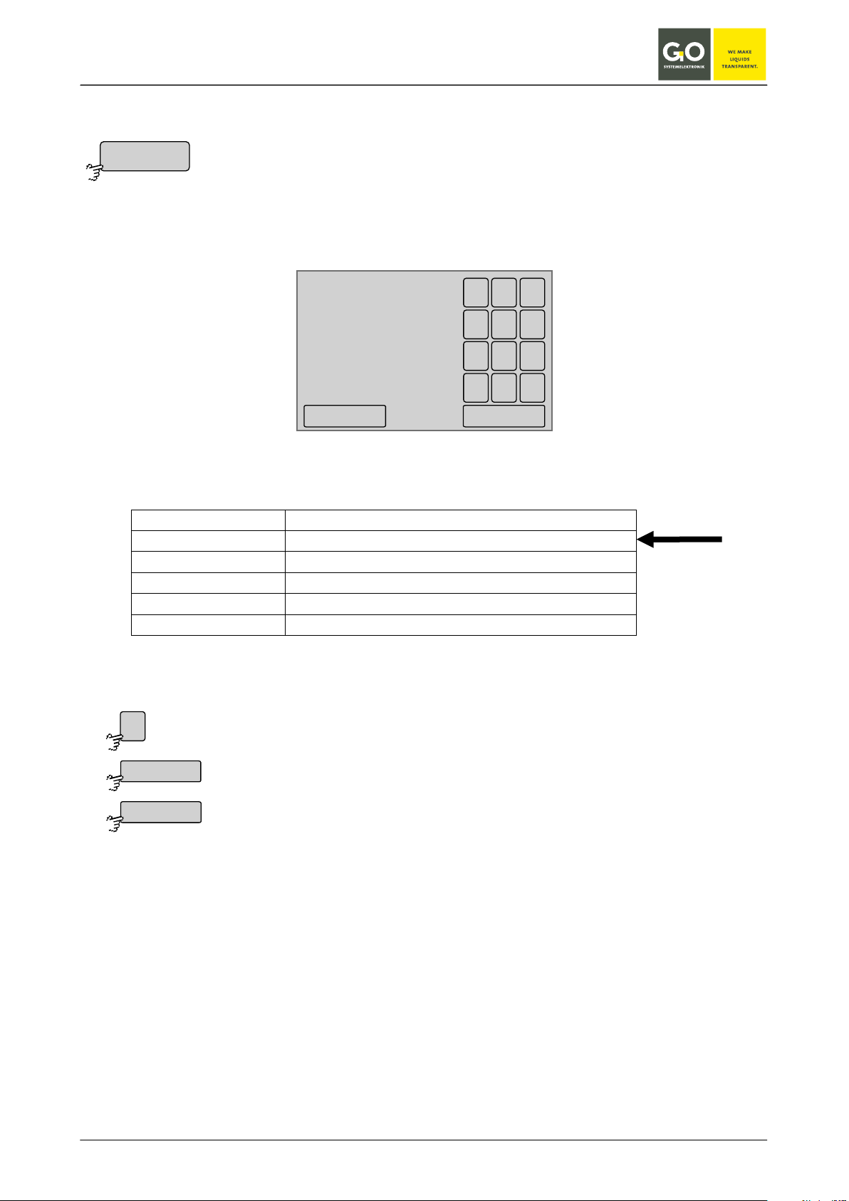
Deletes the last entered digit.
Verifies the password and switches to the System menu.
<
<–
Password input
Call-up the System menu 8.2.1 requires a password consisting of 4 digits. The password can be found in the
configuration data sheet.
Passw o rd
****
1 2 3
4 5 6
708 9
<
<–
If the password is incorrect, you receive an error message.
GO Systemelektronik GmbH Faluner Weg 1 24109 Kiel Germany Tel.: +49(0)431-58080-0 Fax: -58080-11
www.go-sys.de info@go-sys.de
Page 24 / 77

BlueBox
Switches to the Parameter display of the previous sensor.
Switches to the Parameter display of the next sensor.
Switches the cycling of the Parameter display on and off.
Switches to the Main menu.
Menu
Setting via Display menu 8.2.1.6
8 The menu operation
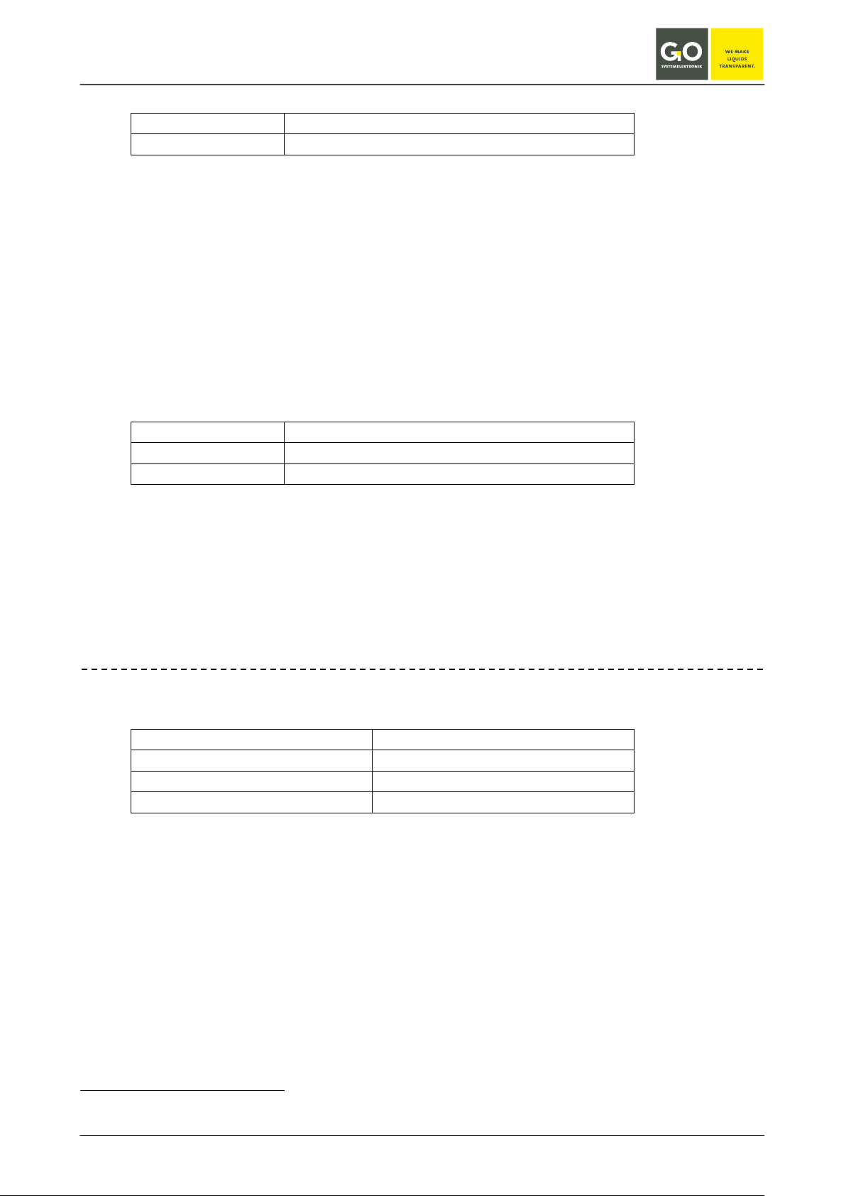
8.1 Parameter display
8.1.1 Single parameter display
Here, as an example, the Parameter display of an oxygen sensor with integrated temperature sensor and a
ph sensor.
The measured value of a sensor is displayed for 6 s, thereafter the display switches in a cycling way to the
display of the next sensor.
1. Oxygen
2. Temperature
3. pH value
20
09:19: 39
10.07. 10
Oxygen
10 mg/l
14
Men u
0
pH value
09:19: 39
10.07. 10
11 pH
60
0
Temperature
Men u
09:19: 39
10.07. 10
18°C
0
Error messages appear instead of the parameter (see Appendix G - Status and error messages).
Switches the cycling of the Parameter display off.
Switches the cycling of the Parameter display off.
Men u
The button is also a status indicator.
Cycling on: In the upper right corner time and date is displayed.
Cycling off: In the upper right corner time and date of the last measurement is displayed.
When there is no user inactivity in all other menus for 2 minutes, the software switches back to the Parameter display.
The bar graph on the left side of the display shows the current measured value.
GO Systemelektronik GmbH Faluner Weg 1 24109 Kiel Germany Tel.: +49(0)431-58080-0 Fax: -58080-11
www.go-sys.de info@go-sys.de
Page 25 / 77

BlueBox
Menu
1/2 09:19:39
10.07.10
oxygen
10 mg/l
temperature outside
18 °C
temperatur inside
22 °C
air pessure
1006.91 hPa
humidity
39.8 %
pH value
11 pH
Switches to the Parameter display of the previous sensor.
Switches to the Parameter display of the next sensor.
Switches the cycling of the Parameter display on and off.
Switches to the Main menu.
Menu
Setting via Display menu 8.2.1.6
8.1.2 Multiple parameter display
Here, as an example, the Parameter display of more than 6 sensors.
The measured values of a the first 6 sensors are displayed for 6 s, the order is alphabetical.
Thereafter the display switches in a cycling way to the display of the next sensors.
There are three ways of displaying the parameters (see display menu 8.2.1.6):
• The parameters of all sensors are displayed.
• Only the parameters of selected sensors and the status of selected actuators are dis-
played. Selection via 8.2.3 Sensor menu and 8.2.5.1 actuator menu
• The parameters of all sensors and the status of all actuators are displayed.
In comparison with the single parameter display error messages are displayed shortened.
Switches the cycling of the Parameter display off.
Switches the cycling of the Parameter display off.
The button is also a status indicator.
When there is no user activity in all other menus for 2 minutes, the software switches back to the Parameter
display.
In the upper left corner you see the page number of the current display and the number of ads displayed (in
this case 1/2).
In the upper right corner time and date is displayed.
GO Systemelektronik GmbH Faluner Weg 1 24109 Kiel Germany Tel.: +49(0)431-58080-0 Fax: -58080-11
www.go-sys.de info@go-sys.de
Page 26 / 77

BlueBox
09:19:39
10.07.10
<–
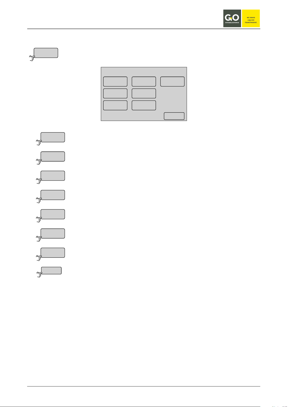
Main menu
Sy stem
Sensor list
Sensor
User
Ac tuator list
Help
Switches to the System menu via a password input (see 7).
Switches to the menu of the Sensor list.
Switches to the Sensor menu of the sensor, which is displayed in the Parameter dis-
Switches to the menu of the User variables.
Switches to the Help menu.
Switches to the Parameter display.
Menu
Sy stem
Sensor list
Sensor
User
Ac tuator list
Help
<–
8.2 Main menu
Parameter display 8.1
play.
Switches to the actuator list.
GO Systemelektronik GmbH Faluner Weg 1 24109 Kiel Germany Tel.: +49(0)431-58080-0 Fax: -58080-11
www.go-sys.de info@go-sys.de
Page 27 / 77
BlueBox
Switches to the Network menu.
Switches to the Time menu.
Shuts down the BlueBox.
Switches to the Modem menu.
Switches to the Display menu.
Switches to the Language menu.
Switches back to the Main menu.
Sy stem
Ne twork
Time
Shut down
Modem
GPS
Display
Language
<–
8.2.1 System menu
Main menu 8.2
System menu
Ne twork
Modem
09:19:39
10.07.10
Language
Time
Shut down
GPS
Display
<–
Switches to the GPS menu.
GO Systemelektronik GmbH Faluner Weg 1 24109 Kiel Germany Tel.: +49(0)431-58080-0 Fax: -58080-11
www.go-sys.de info@go-sys.de
Page 28 / 77

BlueBox
Switches to the input of the IP address of the device, which executes the connection to
Switches to the input of the IP address of a timeserver.
Switches to the settings of a direct Internet connection.
Switches to the Info menu.
Switches back to the System menu.
Ne twork
IP-Address
IP-Netmask
Gat eway
Timeser ver
In ternet
Info
8.2.1.1 Network Menu
System menu 8.2.1
The network connection allows data exchange with the BlueBox and a remote control.
To ensure the accuracy of the timing, you can synchronize the time setting of the BlueBox with a timeserver.
Networ k menu
IP-Address Timeser ver
09:19:39
10.07.10
IP-Netmask
Gat eway
In ternet
Info
<–
Switches to the input of the local IP address.
Switches to the input of the local Netmask.
other networks.
GO Systemelektronik GmbH Faluner Weg 1 24109 Kiel Germany Tel.: +49(0)431-58080-0 Fax: -58080-11
www.go-sys.de info@go-sys.de
Page 29 / 77

BlueBox
Network menu 8.2.1.1
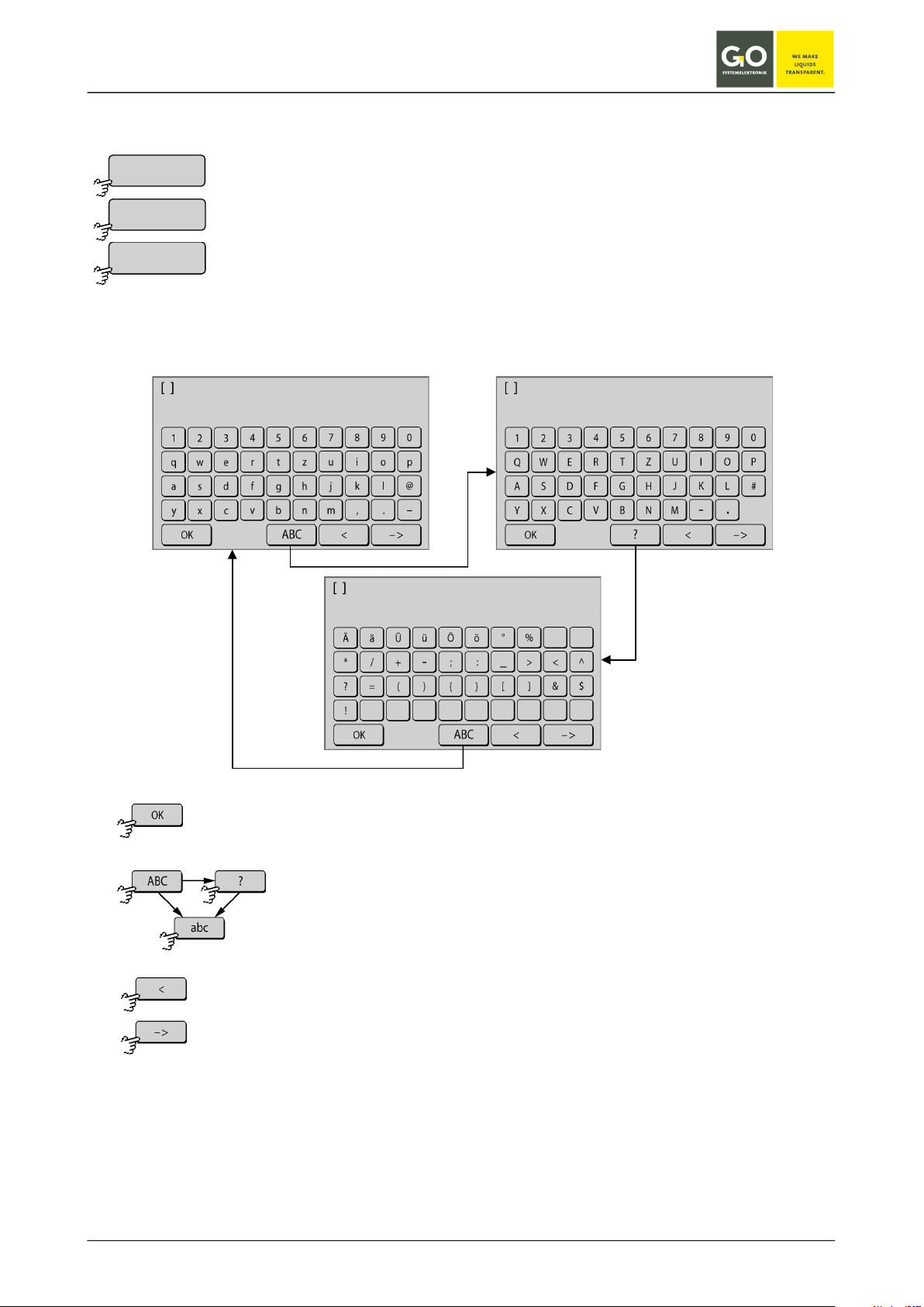
Deletes the last entered character.
Saves the IP address.
Switches back to the Network menu.
IP-Address
<
Ok
<–
8.2.1.1.1 IP-Address menu
Here you can change the IP address, which identifies the BlueBox on your local network.
The IP address is configured at the factory (see 6 The configuration data sheet).
The current value is displayed.
1
4 5
7
0
2 3
8
.
6
9
<
IP-Address
192.168.1.169
input of the IP address with the numeric keys
Network:
IP Address
192.168.1.167
Netmask 255.255.255.0
Gateway 0.0.0.0
Port 14111
Login Name bluebox
Password xxxxx
see 6 The configuration data sheet
<–Ok
GO Systemelektronik GmbH Faluner Weg 1 24109 Kiel Germany Tel.: +49(0)431-58080-0 Fax: -58080-11
www.go-sys.de info@go-sys.de
Page 30 / 77
BlueBox
Network menu 8.2.1.1
Saves the netmask..
IP-Netmask
Netmask
255.255.255.0
1 2 3
4 5 6
708 9
.
<
<–Ok
<
Ok
<–
255.255.255.0
8.2.1.1.2 Netmask menu
Here you can change the netmask, the netmask defines the IP address range of the network ..
The netmask is configured at the factory (see 6 The configuration data sheet).
The current value is displayed.
input of the netmask with the numeric keys
Network:
IP Address 192.168.1.167
Netmask
Gateway 0.0.0.0
Port 14111
Login Name bluebox
Password xxxxx
see 6 The configuration data sheet
Deletes the last entered character.
GO Systemelektronik GmbH Faluner Weg 1 24109 Kiel Germany Tel.: +49(0)431-58080-0 Fax: -58080-11
www.go-sys.de info@go-sys.de
Switches back to the Network menu.
Page 31 / 77

BlueBox
Network menu 8.2.1.1
Deletes the last entered character.
Saves the IP address of the gateway
Switches back to the Network menu.
Gat eway
<
Ok
<–
8.2.1.1.3 Gateway IP-Address (default gateway)
If the BlueBox shall communicate via the LAN connection with other networks, enter the IP address of the
device that executes the connection (another BlueBox, routers, servers, etc.).
The current value is displayed.
Gateway
0.0.0.0
Ok
1 2 3
4 5 6
7
8
0
.
<–
9
<
input of the IP address of the gateway with the numeric keys
Network:
IP Address 192.168.1.167
Netmask 255.255.255.0
Gateway
0.0.0.0
Port 14111
Login Name bluebox
Password xxxxx
see 6 The configuration settings sheet, default 0.0.0.0
GO Systemelektronik GmbH Faluner Weg 1 24109 Kiel Germany Tel.: +49(0)431-58080-0 Fax: -58080-11
www.go-sys.de info@go-sys.de
Page 32 / 77

BlueBox
Network menu 8.2.1.1
Saves the input and switches back to the Network menu settings.
Timeser ver
Switches between the three input menu back and forth.
Deletes the last entered character.
Switches back to the Network menu without saving the input.
8.2.1.1.4 Input timeserver
After entering an IP address or a Web address of a time server, the BlueBox automatically synchronizes your
system time with the server time. The current IP address or web address is displayed.
GO Systemelektronik GmbH Faluner Weg 1 24109 Kiel Germany Tel.: +49(0)431-58080-0 Fax: -58080-11
www.go-sys.de info@go-sys.de
Page 33 / 77

BlueBox
Network menu 8.2.1.1
Switches to the menu of the UDP settings. UDP = User Datagram Protocol
Switches to the menu of the DynDNS settings of the Internet connection. Only
For service tasks GO Systemelektronik can access from the outside to the
Switches back to the Network menu.
In ternet
09:19:39
10.07.10
<–
Internet settings
UDP settings Ser vice enabled
DynDNS settings
Gat eway settings
UDP settings
Gat eway settings
DynDNS settings
Ser vice enabled
Ser vice disabled
<–
8.2.1.1.5 Internet settings
From this menu you can determine the manner of connection of the Blue Box to a computer on the Internet
and set the connection on and off.
Requires an Internet connection via the network cable to the BlueBox or an Internet connection via an internal or external
∗
GPRS/UMTS modem (see 8.2.1.4 Modem menu).
Internet settings
UDP settings S er vic e disabled
Gat eway settings
DynDNS settings
09:19:39
10.07.10
<–
View Service enabled View Service disabled
Switches to the menu of the Gateway settings of the Internet connection.
by a connection via GPRS/UMTS modem.
BlueBox.
Service enabled: access to the operating system functions of BlueBox
Service disabled: no access to operating system functions of BlueBox
Default: Service enabled
The button is also a status indicator.
∗
External modems are not supported from GO Systemelektronik.
GO Systemelektronik GmbH Faluner Weg 1 24109 Kiel Germany Tel.: +49(0)431-58080-0 Fax: -58080-11
www.go-sys.de info@go-sys.de
Page 34 / 77

BlueBox
Menu Internet settings 8.2.1.1.5
Switches to the input of the IP address of the destination computer.
Switches the AES encryption of the connection off and on.
Switches to the setting of the encryption password.
UDP settings
IP-Address
Encryption on
Encryption off
Passw ord
<–
8.2.1.1.5.1 UDP settings
The UDP settings are necessary for the transmission of measurement data to a PC (e.g. for the online data
service BlueGate).
UDP settings
IP-Address
09:19:39
10.07.10
UDP settings
IP-Address
09:19:39
10.07.10
Encryption on
Passw ord
<–
Encryption off
<–
View Encryption on View Encryption off
The button is also a status indicator.
Default = Encryption off
The button is also a status indicator.
Only visible at <Enxcryption on>.
Switches back to the menu Internet settings.
GO Systemelektronik GmbH Faluner Weg 1 24109 Kiel Germany Tel.: +49(0)431-58080-0 Fax: -58080-11
www.go-sys.de info@go-sys.de
Page 35 / 77

BlueBox
Menu UDP settings 8.2.1.1.5.1
Deletes the last entered character.
Saves the IP address.
Switches back to the menu UDP settings.
IP-Address
91.221.182.141
1 2 3
4 5 6
708 9
.
<
<–O k
<
Ok
<–
8.2.1.1.5.1.1 Setting IP address (UDP)
Here you can enter the IP address of the destination computer in the Internet, to which the measuring data is
transmitted. The UDP protocol via port 14112 is used for the transmission. The current IP address is shown.
If a access to the BlueGate server was ordered, the IP address of the BlueBox is set to the default address
91.221.182.141 upon delivery.
BlueGate Settings:
IP Address
Password BlueGate xxxxx
see 6 The configuration data sheet
see also 8.2.1.1.5.2 Gateway settings (Internet)
91.221.182.141
GO Systemelektronik GmbH Faluner Weg 1 24109 Kiel Germany Tel.: +49(0)431-58080-0 Fax: -58080-11
www.go-sys.de info@go-sys.de
Page 36 / 77

BlueBox
Menu UDP settings 8.2.1.1.5.1
Saves the input and switches back to the Menu UDP settings.
Passw ord
Switches between the three input menu back and forth.
Deletes the last entered character.
8.2.1.1.5.1.2 Determine the password of the encryption
The current setting is displayed.
Switches back to the Menu UDP settings without saving the input.
BlueGate Settings:
IP Address 91.221.182.141
Password BlueGate
see 6 The configuration settings sheet
see also 8.2.1.1.5.2 Gateway settings (Internet)
xxxxx
GO Systemelektronik GmbH Faluner Weg 1 24109 Kiel Germany Tel.: +49(0)431-58080-0 Fax: -58080-11
www.go-sys.de info@go-sys.de
Page 37 / 77

BlueBox
Menu Internet settings 8.2.1.1.5
Input of the IP address of the gateway.
Input of the password of the gateway.
Switches back to the Menu Internet settings.
xxxxx Gateway PW
Gat eway settings
Gat eway IP
Gat eway PW
<–
8.2.1.1.5.2 Gateway settings (Internet)
If the BlueBox shall communicate bidirectional with a computer in the Internet, enter here the IP address of
your BlueBox gateway and the associated password.
IP address and password you get from GO Systemelektronik (see 6 The configuration data sheet).
.
Gateway settings
Gat eway IP
Gat eway PW
09:19:39
10.07.10
BlueGate Settings:
IP Address
Password BlueGate
see 6 The configuration data sheet
A gateway is necessary if any of those conditions is met:
91.221.182.141 Gateway IP
<–
1. The UMTS Internet connection has, assigned by the provider, a private IP address.
-
private IP address space: 10.0.0.0 – 10.255.255.255
172.16.0.0 – 172.31.255.255
192.168.0.0 – 192.168.255.255
-
2. Your provider blocks access from the Internet with a firewall.
3. More than one BlueBox is connected with the Internet via a UMTS modem.
GO Systemelektronik GmbH Faluner Weg 1 24109 Kiel Germany Tel.: +49(0)431-58080-0 Fax: -58080-11
www.go-sys.de info@go-sys.de
Page 38 / 77

BlueBox
Menu Gateway settings (Internet) 8.2.1.1.5.2
Saves the input and switches back to the Menu Gateway settings (Internet).
Gat eway IP
Gat eway PW
Switches between the three input menus back and forth.
Deletes the last entered character.
8.2.1.1.5.2.1 Input gateway settings (Internet)
Input of the IP address or web address of the gateway and input of the password of this connection.
The current setting is displayed.
Switches back to the Menu Gateway settings (Internet) without saving the input.
GO Systemelektronik GmbH Faluner Weg 1 24109 Kiel Germany Tel.: +49(0)431-58080-0 Fax: -58080-11
www.go-sys.de info@go-sys.de
Page 39 / 77

BlueBox
Menu Internet settings 8.2.1.1.5
Input Name under which the BlueBox on DynDNS can be reached
Input Login Username of your DynDNS account
Input Login password of your DynDNS account
Switches back to the menu Internet settings.
DynDNS settings
Host
Username
Passw ord
<–
8.2.1.1.5.3 DynDNS settings
Here you can enter the DynDNS settings.
For the correct entries: Contact your DynDNS provider.
Currently only the DynDNS service www.dyndns.org is supported.
DynDNS settings
Host
Username
Passw ord
09:19:39
10.07.10
<–
If you need no Internet gateway (see 1.1.2), you can access via a DynDNS service from the Internet on the
BlueBox.
Condition is:
1. Your GPRS / UMTS Internet connection has a public IP address.
2. The access is not blocked by the provider.
Note:
In the Network settings
off the BlueBox in the
BlueBox Software the
encryption of the connection must be enabled.
There are no approved
non-encrypted connections over the Internet.
GO Systemelektronik GmbH Faluner Weg 1 24109 Kiel Germany Tel.: +49(0)431-58080-0 Fax: -58080-11
www.go-sys.de info@go-sys.de
Page 40 / 77
BlueBox
DynDNS settings 8.2.1.1.5.3
Host
Username
Passw ord
Switches between the three input menu back and forth.
Deletes the last entered character.
Switches back to the Menu DynDNS without saving the input.
8.2.1.1.5.3.1 Input DynDNS settings
The current setting is displayed.
Saves the input and switches back to the Menu DynDNS settings.
GO Systemelektronik GmbH Faluner Weg 1 24109 Kiel Germany Tel.: +49(0)431-58080-0 Fax: -58080-11
www.go-sys.de info@go-sys.de
Page 41 / 77

BlueBox
Network menu 8.2.1.1
Switches back to the Network menu.
Info
<–
System menu 8.2.1
Switches to the input of the date.
Switches to the input of the time.
Switches to the input of the time zone.
Switches to the input of the time drift.
Switches back to the System menu.
Time
Da te
Time
Time z one
Time drift
<–
8.2.1.1.6 Info Network
Here the current network settings are listed.
Info
IP-Addr ess 192.168.1.60
Netmask 255.255.255.0
Ga tewa y 0.0.0.0
Timeser ver (no sync)
8.2.1.2 Time menu
Time
Da te
Time
Time z one
Time drift
<–
09:19:39
10.07.10
GO Systemelektronik GmbH Faluner Weg 1 24109 Kiel Germany Tel.: +49(0)431-58080-0 Fax: -58080-11
www.go-sys.de info@go-sys.de
<–
Page 42 / 77
BlueBox
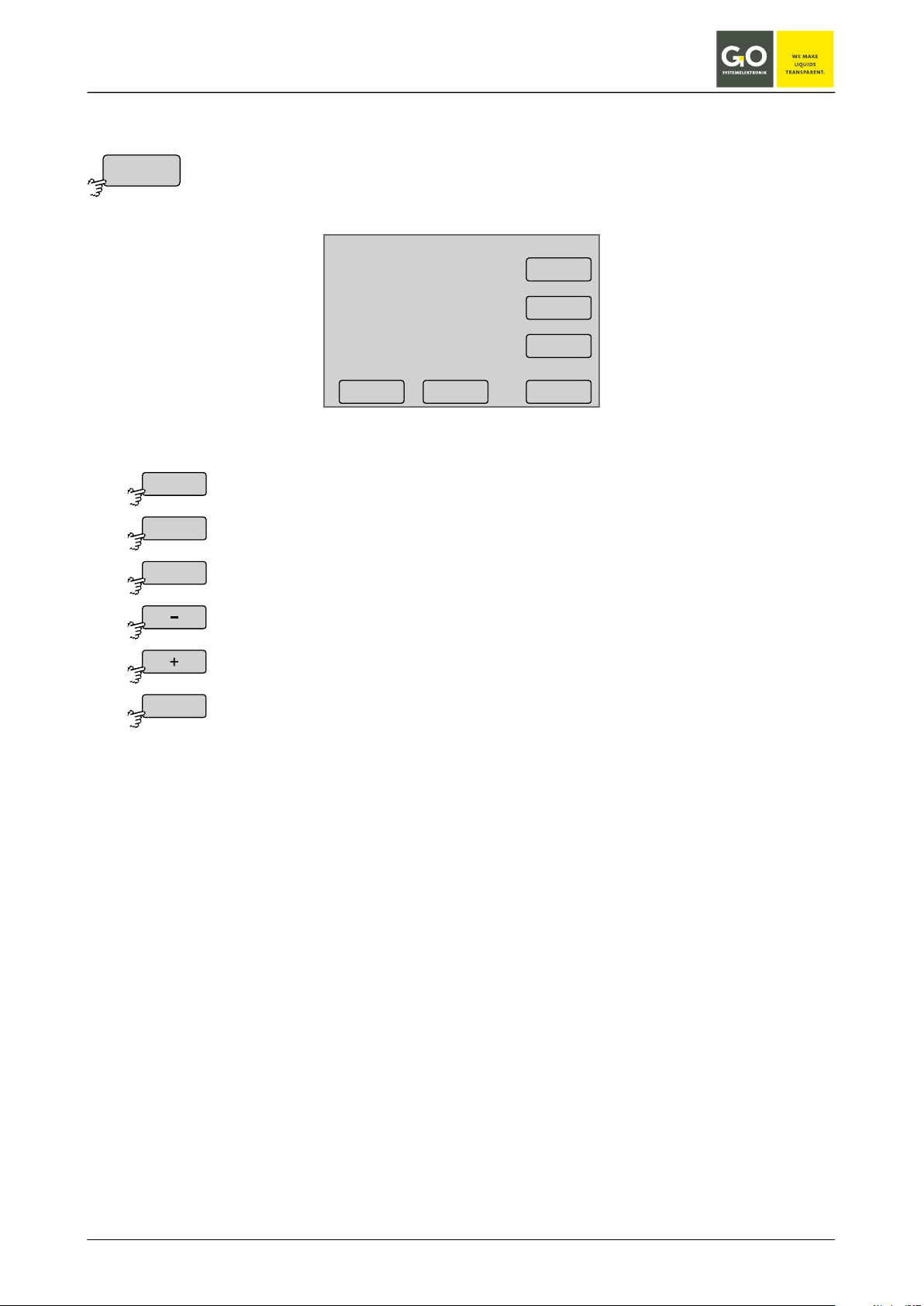
8.2.1.2 Time menu
Selection of day setting
Selection of month setting
selection -1
selection +1
Da te
Da y
Mon th
Year
<–
8.2.1.2.1 Date menu
Date
Da y
10.07.10
- +
Selection of year setting
Switches back to the Time menu.
Mon th
Year
<–
GO Systemelektronik GmbH Faluner Weg 1 24109 Kiel Germany Tel.: +49(0)431-58080-0 Fax: -58080-11
www.go-sys.de info@go-sys.de
Page 43 / 77
BlueBox
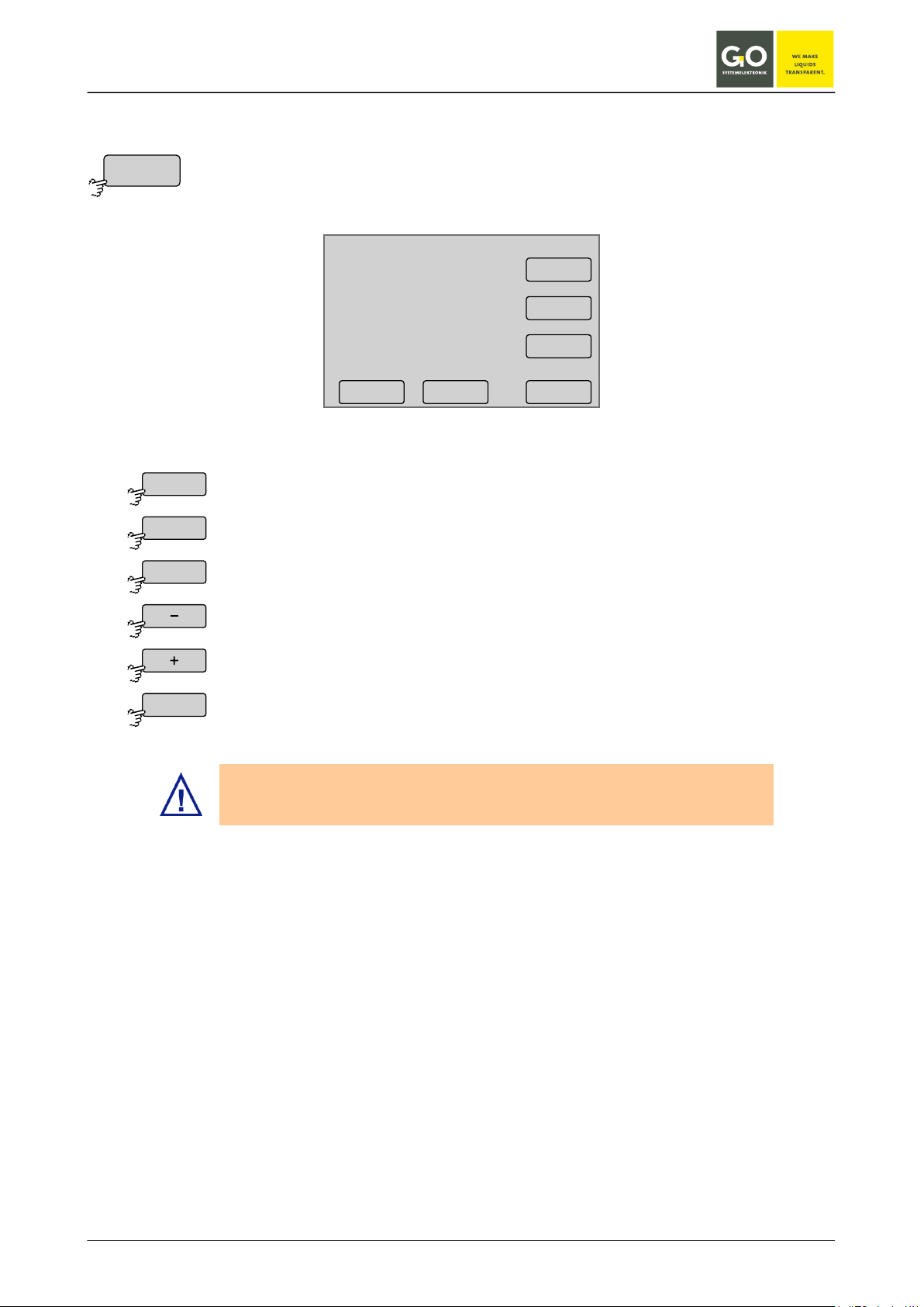
8.2.1.2 Time menu
Selection of hour setting
Selection of second setting
selection -1
selection +1
Switches back to the Time menu.
Summer time is adjusted only by changing the time zone (e.g. from +1 to +2).
Time
Hour
Min
Sec
<–
8.2.1.2.2 Time menu
Time
Hour
09:19:39
Selection of minute setting
- +
Min
Sec
<–
First set the time zone before you set the time.
GO Systemelektronik GmbH Faluner Weg 1 24109 Kiel Germany Tel.: +49(0)431-58080-0 Fax: -58080-11
www.go-sys.de info@go-sys.de
Page 44 / 77

BlueBox
8.2.1.2 Time menu
on the data-bound time.
time zone +0,25
Switches back to the Time menu.
8.2.1.2 Time menu
Deletes the last entered character.
Saves the input and switches back to the Time menu.
Time z one
<–
Time drift
<
Ok
<–
8.2.1.2.3 Time zone menu
Time zone
09:19:39
10.07.10
+ 2:00 h
Please note that the setting described here only has impact on the displayed time zone and not
time zone -0,25
8.2.1.2.4 Time drift menu
- +
<--
Time dr i f t per day
The time drift refers to the daily clock drift of the internal clock. Enter the value of the clock drift in seconds
here and the clock drift is corrected.
Switches back to the Time menu without saving the input.
GO Systemelektronik GmbH Faluner Weg 1 24109 Kiel Germany Tel.: +49(0)431-58080-0 Fax: -58080-11
www.go-sys.de info@go-sys.de
0.00s
1 2 3
4 5 6
708 9
.
<–O k
<
Page 45 / 77

BlueBox
Shutdown of the BlueBox
Switches back to the System menu
Shut down
Yes
No
8.2.1.3 Shutdown
System menu 8.2.1
For a proper operation it is necessary to shut down the BlueBox before disconnecting the power supply.
Shutdown?
YES NO
09:19:39
10.07.10
The state of the shutdown is displayed.
System shuts down
BlueBox
halt
Shutdow n
BlueBox
BlueBox
is down
If the BlueBox is not disconnected from the power supply after shutdown, it restarts again
automatically after 10 minutes.
GO Systemelektronik GmbH Faluner Weg 1 24109 Kiel Germany Tel.: +49(0)431-58080-0 Fax: -58080-11
www.go-sys.de info@go-sys.de
The shutdown is complete.
You can turn off the BlueBox by interrupting the power supply.
Page 46 / 77

BlueBox
Switches to the Modem port setup.
Switches to the input of the PIN number of the modem.
Switches to the modem type settings.
Switches to the Info menu of the modem settings.
Switches back to the System menu.
Modem
Po rt
PIN
Modem t ype
UMTS
Info
<–
8.2.1.4 Modem menu / Modem settings
System menu 8.2.1
The view varies depending on the selected modem type (see: 8.2.1.4.3 Modem type settings).
Modem menu
Po rt
Modem t ype
09:19:39
10.07.10
PIN
UMTS
Info
<–
Only visible if modem type <GSM> or <GPRS/UMTS> is selected in the Modem type
settings (see: 8.2.1.4.3 Modem type settings).
Switches to the UMTS settings.
Only visible if modem type <GPRS/UMTS> is selected in the Modem type settings
(see: 8.2.1.4.3 Modem type settings ).
GO Systemelektronik GmbH Faluner Weg 1 24109 Kiel Germany Tel.: +49(0)431-58080-0 Fax: -58080-11
www.go-sys.de info@go-sys.de
Page 47 / 77

BlueBox
If a factory-mounted modem is connected to the USB interface, then the USB
For special cases, e.g. if USB 1 is allocated to a GPS receiver.
Switches back to the Modem Menu.
Po rt
Off
Off
Ser ial 1
Ser ial 1
USB 1
USB 1
<–
8.2.1.4.1 Modem port setup
Modem menu 8.2.1.4
Modem por t setup
Off
Ser ial 1
USB 1
USB 2
Enables or disables the modem connection.
If a factory-mounted modem is connected to the serial interface, then this interface is activated by the manufacturer.
interface is activated for the modem by the manufacturer via this button.
<–
GO Systemelektronik GmbH Faluner Weg 1 24109 Kiel Germany Tel.: +49(0)431-58080-0 Fax: -58080-11
www.go-sys.de info@go-sys.de
Page 48 / 77

BlueBox
otherwise the UMTS card will be disabled by standardly repeated queries.
Switches back to the Modem Menu without saving the input.
PIN
<
Ok
<–
8.2.1.4.2 Input of the PIN number
Modem menu 8.2.1.4
It is important to change the PIN number before installing or activating a new UMTS card, as
Input of the PIN number with the numeric keys
Deletes the last entered character.
Saves the input and switches back to the Modem Menu.
Modem PIN
Ok
1 2 3
4 5
708
<
<–
6
9
GO Systemelektronik GmbH Faluner Weg 1 24109 Kiel Germany Tel.: +49(0)431-58080-0 Fax: -58080-11
www.go-sys.de info@go-sys.de
Page 49 / 77

BlueBox
No modem is connected.
An ISDN modem is connected.
An Analogue modem is connected.
A GPRS modem* or a UMTS modem is connected.
Saves the input and switches back to the Modem Menu.
Modem t ype
Off
Off
GSM
GSM
ISDN
ISDN
Analog
Analog
GPRS/UMT S
GPRS/UMT S
<–
8.2.1.4.3 Modem type settings
Modem menu 8.2.1.4
From this menu, the type of a connected modem is set.
Modem type
Off
GSM GPRS/UMT S
ISDN
A GSM modem∗ is connected.
Analog
<–
∗
optional extra equipment
GO Systemelektronik GmbH Faluner Weg 1 24109 Kiel Germany Tel.: +49(0)431-58080-0 Fax: -58080-11
www.go-sys.de info@go-sys.de
Page 50 / 77

BlueBox
Input APN (Access Point Name)
Input Password (Login password)
Switches the routing on and off.
Switches back to the Modem Menu.
UMTS
APN
Username
Passw ord
Routing enabled
Routing disabled
<–
8.2.1.4.4 UMTS settings
Modem menu 8.2.1.4
From this menu, you set up your UMTS connection. For APN, username and password, contact your UMTS
provider.
UMTS settings
APN
Username Passw ord
Routing disabled
<–
Input Username (Login name)
The button is also a status indicator.
Factory default: routing off
The routing must be switched on, if you use this BlueBox as an Internet router. This is for example the case,
when via this BlueBox other BlueBoxes send measured values.
Please note that the connected BlueBoxes must use the IP address of the routing BlueBox as the address of
the default gateway see (8.2.1.1.3).
GO Systemelektronik GmbH Faluner Weg 1 24109 Kiel Germany Tel.: +49(0)431-58080-0 Fax: -58080-11
www.go-sys.de info@go-sys.de
Page 51 / 77

BlueBox
Saves the input and switches
APN
Username
Passw ord
<–
Modem Info
APN : nn
User name : nn
Passw or d : nn
IP-Addr ess : nn
RX byt es : nn
TX byt es : nn
Switches between the three in-
Deletes the last entered character.
Switches back to the Menu UMTS settings without saving the input.
Modem menu 8.2.1.4
Info
8.2.1.4.4.1 Input UMTS settings
UMTS settings 8.2.1.4.4
The current setting is displayed.
back to the Menu UMTS settings.
8.2.1.4.5 Modem Info (UMTS)
put menu back and forth.
Display of the actual settings of the UMTS modem
RX bytes: received data since connection started
TX bytes: transfered data since connection started
GO Systemelektronik GmbH Faluner Weg 1 24109 Kiel Germany Tel.: +49(0)431-58080-0 Fax: -58080-11
www.go-sys.de info@go-sys.de
Page 52 / 77

BlueBox
Switches to the settings of the connection of a GPS receiver.
Switches to the information menu of the GPS connection, here are the relevant GPS
Switches back to the System menu
Enables or disables the GPS connection.
If a factory-mounted GPS receiver is connected to the serial interface, then this inter-
If a factory-mounted GPS receiver is connected to the USB interface and USB 1 is not
If a factory-mounted GPS receiver is connected to the USB interface and USB 1 is
Switches back to the GPS menu.
GPS
Po rt
Info
<–
Po rt
Off
Off
Ser ial 1
Ser ial 1
USB 1
USB 1
USB 2
USB 2
<–
8.2.1.5 GPS Menu
System menu 8.2.1
data listed.
8.2.1.5.1 GPS Port Setup
GPS Menu
Po rt
Info
09:19:39
10.07.10
<–
GPS menu 8.2.1.5
GPS P o r t Setup
Off
Ser ial 1
USB 1
USB 2
09:19:39
10.07.10
<–
face is activated by the manufacturer.
allocated to a modem, then the USB interface is activated for the GPS receiver by the
manufacturer via this button.
allocated to a modem, then the USB interface is activated for the GPS receiver by the
manufacturer via this button.
GO Systemelektronik GmbH Faluner Weg 1 24109 Kiel Germany Tel.: +49(0)431-58080-0 Fax: -58080-11
www.go-sys.de info@go-sys.de
Page 53 / 77

BlueBox
Switches the parameter display between the single mode and
Defines with sensors/actuators will be displayed in the multiple
Switches back to the system menu.
Display
Display 6 sensors
Display 1 sensor
Sensors & ac tuators
Selec ted sensors
Only sensors
<–
8.2.1.6 Display
System menu 8.2.1
Display
Light
Dark
Display 1 sensor
Selec ted sensors
09:19:39
10.07.10
<–
Press a point on the bar for Light or Dark to set the value of the backlight of the display.
When there is no user activity, after 150 seconds the software turns the backlight of the display to the value
of Light to the value of Dark. If there is user activity it switches back.
At an elevated temperature of the CPU the Dark value is ignored and the backlight of the display is switched
off.
the multiple mode back and forth (see 8.1 Parameter display).
The button is also a status indicator.
parameter display (see 8.1.2 Multiple parameter display).
The button is also a status indicator.
There are three posibilities:
• Only the parameters of selected sensors and the status of
selected actuators are displayed. Selection via 8.2.3 Sensor
menu and 8.2.5.1 actuator menu
• The parameters of all sensors and the status of all actuators
are displayed.
• The parameters of all sensors are displayed.
GO Systemelektronik GmbH Faluner Weg 1 24109 Kiel Germany Tel.: +49(0)431-58080-0 Fax: -58080-11
www.go-sys.de info@go-sys.de
Page 54 / 77

BlueBox
Selection menu language German, the button is also a status indicator.
Selection menu language English, the button is also a status indicator.
Selection menu language French, the button is also a status indicator.
Switches back to the system menu.
Language
Deutsch
English
Español
Fr ançaise
<–
8.2.1.7 Language settings
System menu 8.2.1
Language settings
Deutsch
English
Español
Fr ançaise
Selection menu language Spanish, the button is also a status indicator.
<–
GO Systemelektronik GmbH Faluner Weg 1 24109 Kiel Germany Tel.: +49(0)431-58080-0 Fax: -58080-11
www.go-sys.de info@go-sys.de
Page 55 / 77

BlueBox
Switches to the menu of the oxygen sensor.
Switches to the menu of the pH sensor.
Switches to the menu of the temperature sensor.
Scrolls the list.
Switches back to the Main menu.
Sensor list
Ox ygen
pH v alue
Tempera ture
<–
8.2.2 Sensor list
Main menu 8.2
Use this menu to access the menu of the connected sensors.
1/1
Ox ygen
pH v alue
Tempera ture
<–
The buttons of the sensors are arranged alphabetically. If necessary you can change a sensor name with the
AMS software.
In the example chosen here is the
1st Sensor, an oxygen sensor.
2nd Sensor, a pH sensor.
3rd Sensor, a temperature sensor.
GO Systemelektronik GmbH Faluner Weg 1 24109 Kiel Germany Tel.: +49(0)431-58080-0 Fax: -58080-11
www.go-sys.de info@go-sys.de
Page 56 / 77
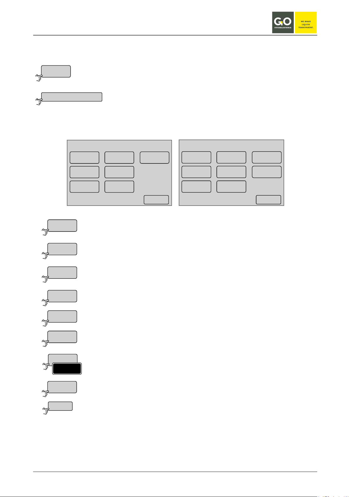
BlueBox
09:19:39
10.07.10
<–
pH v alue
In ter val
Av erage
Calib ration
Table
Diagram
Info
Selec ted
Cal. mo de
Main menu 8.2
Sensor list 8.2.2
Switches to the input of the measurement average.
Switches to the calibration menus.
Switches to the table display.
Switches to the sensor information.
Selects the sensor for the multiple parameter display or not.
Switches to the menu for the selection of the calibration mode.
Sensor
Ox ygen
In ter val
Av erage
Calib ration
Table
Diagram
Info
Selec ted
Selec ted
Cal. mo de
<–
8.2.3 Sensor menu
Example oxygen
Switches to the Sensor menu of the sensor, which is displayed in the Parameter
display.
From this menu you can determine the settings of a connected sensor and calibrate it (if necessary), represent their values over time and see the current settings of the sensor. For the specific settings of the connected sensor, please refer to the description of the sensors.
Oxygen
In ter val
Av erage
Calib ration
Table
Diagram
Info
09:19:39
10.07.10
Selec ted
<–
Switches to the input of the measurement interval.
Switches to the diagram display.
see also 8.2.1.6 Display
Only visible with sensors, in which a selection of calibration mode is possible.
Switches back to the sensor menu.
GO Systemelektronik GmbH Faluner Weg 1 24109 Kiel Germany Tel.: +49(0)431-58080-0 Fax: -58080-11
www.go-sys.de info@go-sys.de
Page 57 / 77

BlueBox
measurement cycle
interval
new
measurement
measuring
time
single
measurements
(here 5)
In ter val
Av erage
<
Ok
<–
8.2.3.1 Interval and Average
Sensor menu 8.2.3
Interval: Period in seconds between the end of a measurement and the end of the next measurement.
Choose the interval according to the characteristics of the sensor. Each sensor requires a certain minimum
period for measuring a value.
Please note the data sheet of the sensor.
The higher the interval is set, the fewer measurements are taken, the shorter the download time.
Averaging: The measured value is the arithmetic average of the selected number of single measurements.
Inter v al
Aktual value 60
Ok
1 2 3
4 5 6
708 9
<
<–
Av e r age
Aktual value 6
1 2 3
4 5 6
708 9
<
<–O k
Current settings are displayed as "Actual value".
Deletes the last entered character.
Saves the input and switches back to the Sensor menu.
Switches back to the Sensor menu without saving the input.
GO Systemelektronik GmbH Faluner Weg 1 24109 Kiel Germany Tel.: +49(0)431-58080-0 Fax: -58080-11
www.go-sys.de info@go-sys.de
Page 58 / 77

BlueBox
Switches to the input of the first measuring point.
Switches back to the sensor menu.
Calib ration
Set
<–
8.2.3.2 Calibration
Sensor menu 8.2.3
The BlueBox allows calibration of sensors in the connected state. Calibration is password protected, see: 7
Switching on the BlueBox and password input.
Oxygen
O xy gen calibr a tion
09:19:39
10.07.10
0.0 mg/l
A detailed description of the calibration can be found at:
Appendix B / Calibrating a pH sensor
Appendix C / Calibration of an oxygen sensor
<–Set
GO Systemelektronik GmbH Faluner Weg 1 24109 Kiel Germany Tel.: +49(0)431-58080-0 Fax: -58080-11
www.go-sys.de info@go-sys.de
Page 59 / 77
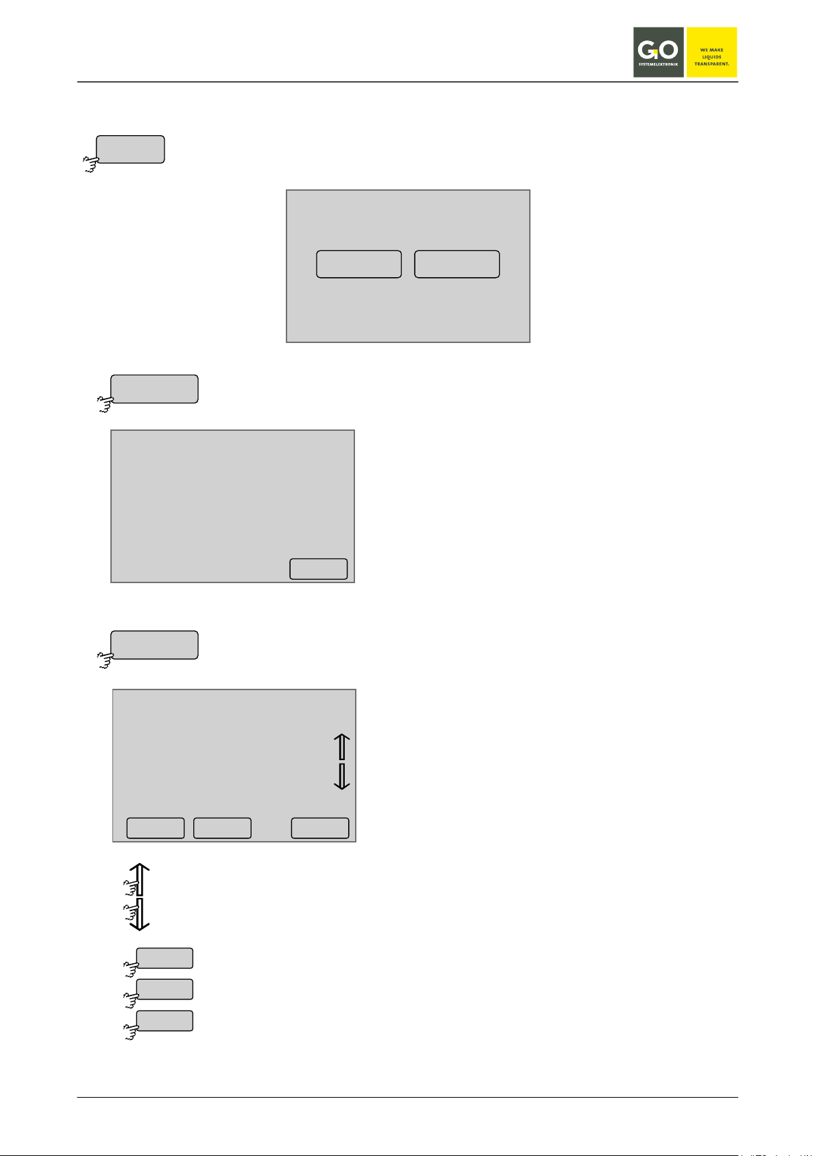
BlueBox
Sensor menu 8.2.3
Scrolls the list.
Displays the measurement values of the previous day.
Displays the measurement values of the nest day.
Switches to the sensor menu.
Table
St atistics
List
<
>
<–
8.2.3.3 Table display (sensor values)
Table
St atistics List
Ox ygen [mg/l]
1h 8.4 10.6 9.4
6h 8.3 9.7 9.2
12h 9.1 11.7 10.0
24h 8.8 10.9 9.4
7d 8.7 11.1 10.8
min. max. mittl.
<–
10.07.10
08:56:38 8.8
08:57:38 8.8
08:58:38 9.0
08:59:38 8.9
09:00:38 9.1
09:01:38 9.2
09:02:38 9.2
Ox ygen [mg/l]
Statistics of the measurement values over the past
24 hours and the last 7 days.
List of the measurement values of one day.
<–< >
GO Systemelektronik GmbH Faluner Weg 1 24109 Kiel Germany Tel.: +49(0)431-58080-0 Fax: -58080-11
www.go-sys.de info@go-sys.de
Page 60 / 77

BlueBox
Diagram
Au to scale
Range
Pushing on the display switches
to the sensor menu.
Pushing on the display switches
to the sensor menu.
8.2.3.4 Diagram display (sensor values)
Sensor menu 8.2.3
Diagram
Au to scale Range
12
11
10
9
8
7
6
5
4
3
2
13 16 19 22 01 04 07 10 13
Ox ygen last 24h
20
18
16
14
12
10
8
6
4
2
0
13 16 19 22 01 04 07 10 13
Ox ygen last 24h
Measurement values over the past 21 - 24 hours
(depending on the range of values), scaled to
min/max of all measured values.
Measurement values over the past 21 - 24 hours
(depending on the range of values).
GO Systemelektronik GmbH Faluner Weg 1 24109 Kiel Germany Tel.: +49(0)431-58080-0 Fax: -58080-11
www.go-sys.de info@go-sys.de
Page 61 / 77
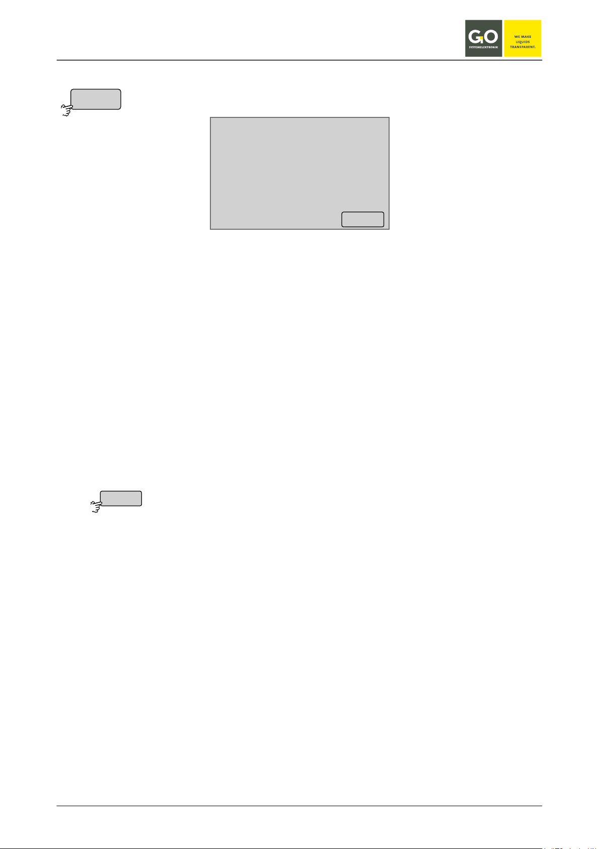
BlueBox
Switches back to the sensor menu.
Info
<–
8.2.3.5 Sensor info
Sensor menu 8.2.3
Oxygen
Comment
Sensor ser ial no. tox000032
In terval 60
Av erage 6
Resolution 0.1
Pa rameter O xy gen
Unit mg/l
Last up dat e 01:33:01 03.04.10
<–
Commnent general comment for the sensor
Sensor serial no DAM-ID (8-digit designation of the Data Acquisition Module) +
run number of the sensor (0-9)
Interval measurement interval of the sensor
Average measurement average
Resolution measurement resolution
Parameter name of the parameter
Unit unit of the parameter
Last update date of the last measurement
GO Systemelektronik GmbH Faluner Weg 1 24109 Kiel Germany Tel.: +49(0)431-58080-0 Fax: -58080-11
www.go-sys.de info@go-sys.de
Page 62 / 77
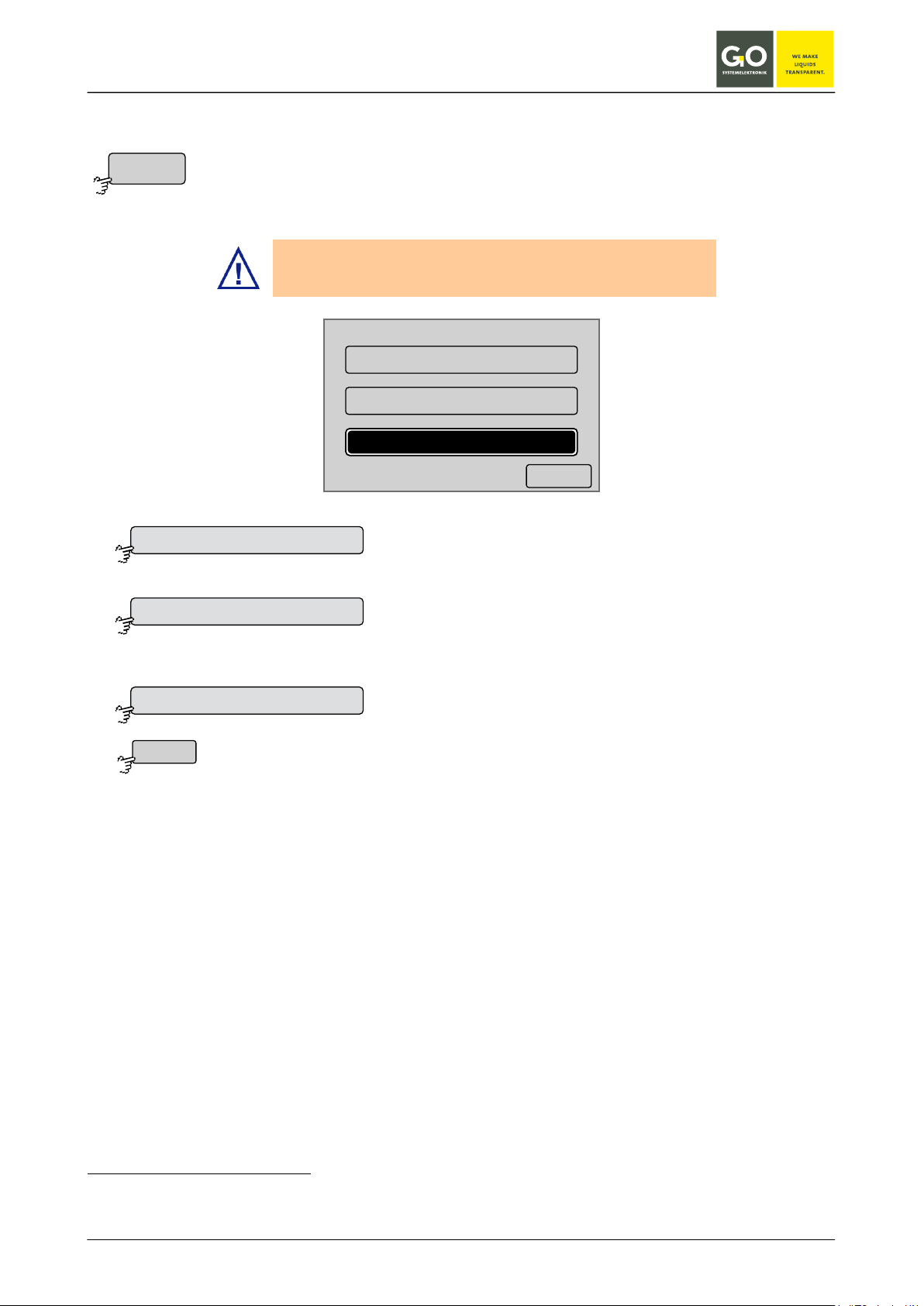
BlueBox
<–
One p oint calibr ation y0=0
One p oint calibr ation y0=fix
Two point calibr ation
Calibration mode one point calibration with with a calibration
Calibration mode one point calibration with with a calibration
Switches back to the sensor menu.
Cal. mo de
One p oint calibr ation y0=0
One p oint calibr ation y0=fix
Two point calibr ation
<–
8.2.3.6 Selection calibration mode
Sensor menu 8.2.3
Here you can set the calibration mode of a sensor.
GO Systemelektronik recommends using the default setting.
curve through the origin.
The button is also a status indicator.
curve thats y0-value is set by the calibration factors of the
sensor.
The button is also a status indicator.
Calibration mode two point calibration
The button is also a status indicator.
The values of the data points are the running average from the last 15 seconds
∗
.
A detailed description of the calibration can be found in:
Appendix B - Calibration of a pH sensor
Appendix C - Calibration of an oxygen sensor
The calibration of the two optional current outputs only happens with the AMS software.
∗
Strictly speaking, these are the last 15 measurement values, but since all connected sensors (in fact all but the ISA
spectrometer) are automatically set to a measurement interval of one second during calibration, it's the running average of the last 15 seconds.
GO Systemelektronik GmbH Faluner Weg 1 24109 Kiel Germany Tel.: +49(0)431-58080-0 Fax: -58080-11
www.go-sys.de info@go-sys.de
Page 63 / 77

BlueBox
Switches to the menu of the first variable.
Switches to the menu of the second variable.
Switches back to the Main menu.
Switches to the input menu of the first variable.
Switches back to the menu of the user variable.
Saves the input and switches back to the menu of the user variable.
switches back to the menu of the user variable without saving the input.
User
<–
Va riable1
Va riable2
1/1
Va riable1
Va riable2
<–
09:19:39
10.07.10
<–Setzen
Va r iable1
2.5
Setzen
<–
Va r iable1
1 2 3
4 5 6
708 9
.
<
<–Ok
<
Ok
<–
8.2.4 User variables
Main menu 8.2
Example with two user variables
The AMS program as part of the BlueBox PC Software allows users to define variables that can be changed
directly in the BlueBox.
menu of the first variable
The current value of the user variable is shown.
input menu of the user variable
Here you can change the value of the user variable.
Deletes the last entered character.
GO Systemelektronik GmbH Faluner Weg 1 24109 Kiel Germany Tel.: +49(0)431-58080-0 Fax: -58080-11
www.go-sys.de info@go-sys.de
Page 64 / 77

BlueBox
Switches to the menu of the first actuator.
Switches to the menu of the second actuator.
Switches back to the Main menu.
Ac tuator list
Rela y 1
Rela y 2
8.2.5 Actuator list
Main menu 8.2
Use this menu to access the menu of the connected actuators.
1/1
Rela y 1
Rela y 2
The buttons of the actuators are arranged alphabetically.
If necessary you can change a sensor name with the AMS software.
In the example chosen here there are two relays.
<–
Scrolls the list.
GO Systemelektronik GmbH Faluner Weg 1 24109 Kiel Germany Tel.: +49(0)431-58080-0 Fax: -58080-11
www.go-sys.de info@go-sys.de
Page 65 / 77

BlueBox
Switches to the diagram display of the actuator behaviour.
Switches to the info menu of the actuator.
Selects the actuator for the multiple parameter display or not.
Switches back to the main menu.
Rela y 1
Set
Diagram
Info
Selec ted
Selec ted
<–
8.2.5.1 Actuator menu
Example Relais 1
Actuator list 8.2.5
Relay 1
Set Diagram
Info
09:19:39
10.07.10
Selec ted
<–
From this menu you can turn on and off a connected actuator and represent his values over time and see the
current settings of the actuator. For the specific settings of the connected actuator, please refer to the description of the actuator.
Switches to the set menu of the actuator.
see also 8.2.1.6 Display
GO Systemelektronik GmbH Faluner Weg 1 24109 Kiel Germany Tel.: +49(0)431-58080-0 Fax: -58080-11
www.go-sys.de info@go-sys.de
Page 66 / 77

BlueBox
Switches the relay on, the button is also a status indicator.
Switches back to the Actuator menu.
Set
ON
OFF
<–
8.2.5.1.1 Actuator setting
Example Relais 1
Actuator menu 8.2.5.1
Relay 1
ON OFF
09:19:39
10.07.10
<–
From this menu you can determine the status of a connected actuator, in this example you can turn a relay
on and off. For the specific settings of the connected actuator, please refer to the description of the actuator.
Switches the relay off, the button is also a status indicator.
GO Systemelektronik GmbH Faluner Weg 1 24109 Kiel Germany Tel.: +49(0)431-58080-0 Fax: -58080-11
www.go-sys.de info@go-sys.de
Page 67 / 77

BlueBox
Actuator menu 8.2.5.1
Switches back to the Actuator menu.
Diagram
Info
<–
8.2.5.2 Diagram display (actuator)
Actuator menu 8.2.5.1
Diagram
Au to scale Range
Displays the status of an actuator over the last 21 to 24 hours (similar 8.2.3.4 Diagram display (sensor values)).
8.2.5.3 Actuator info
Relay 1
Comment Pumpe 1
Sensor ser ial no. fst002788
In terval 300
Av erage 1
Resolution 1
Pa rameter switch
Unit
Last up dat e 01:33:01 03.04.10
<–
Comment general comment for the actuator
Sensor serial no. i.e. actuator number
Interval Inspection interval for the query function of the actuator
Average 1 - default value for actuators
Resolution 1 - default value for actuators
Parameter switch - default value for relays
Unit not used
Last update The update function is used for a function query and happens after
each inspection interval.
GO Systemelektronik GmbH Faluner Weg 1 24109 Kiel Germany Tel.: +49(0)431-58080-0 Fax: -58080-11
www.go-sys.de info@go-sys.de
Page 68 / 77

BlueBox
Switches to the info menu of the system.
Switches to the menus of the plug and clip connection.
Switches back to the Main menu.
Help menu 8.2.6
Help
Info
<–
Info
<–
8.2.6 Help menu
Main menu 8.2
SYSTEMELEKTRONIK
Tel : +49-431-58080-0
Fax : +49-431-58080-11
Info
8.2.6.1 Info menu of the system
<–
System Inf o
Sen sors = 3 / 3
Ac tuators = 0 / 0
Vi rtual Sen sors = 1 / 1
So ft war e V ersion = 2.69.82
UPS = N/V
Switches back to the Help menu.
GO Systemelektronik GmbH Faluner Weg 1 24109 Kiel Germany Tel.: +49(0)431-58080-0 Fax: -58080-11
www.go-sys.de info@go-sys.de
09:19:39
10.07.10
<–
Page 69 / 77

BlueBox
plug male
[ 338 1100 ]
1 gr een C AN-H
2 y ello w C AN-L
3 whit e +24
4 br o wn GND24V
plug f emale
[ 338 1000 ]
3 whit e +24
4 br o wn GND24V
M12 P lug 4
<–
241
3
34
4 C onnect or
<–
1 4
[ 338 0130 ]
1 gr een C AN-H
2 y ello w C AN-L
3 whit e +24V
4 br o wn GND24V
Switches forward.
Switches to the Main menu.
<–
8.2.6.2 Plug and clip connection
Help menu 8.2.6
Shows the pin assignments at the BlueBox for the current version.
plug male: M12-pin connector on the CAN-bus cable
338 1100 is the article number of the M12 pin connector.
plug female: M12 female connector on the power supply cable
338 1000 is the article number of the M12 socket plug.
Color coding is for the GO standard cable.
Shows the terminal connections of the CAN-bus cable into the
sensor modules for socket connectors with 4 contacts.
338 0130 is the article number of the 4-terminal socket con-
nector.
Color coding is for the GO standard cable.
GO Systemelektronik GmbH Faluner Weg 1 24109 Kiel Germany Tel.: +49(0)431-58080-0 Fax: -58080-11
www.go-sys.de info@go-sys.de
Switches back.
GO Systemelektronik GmbH
Page 70 / 77

BlueBox
Appendix A - Adjustment of the touch display
If the display responses not or wrong to a button, a display adjustment is necessary.
While switching on power, press display until
the notice
"touch adjustment ?
don't touch for normal use"
appears.
Left off the display immediately!
Press the display immediately again for more
than one second.
A blinking dot appears at top left.
Press the blinking dot top left.
A blinking dot appears at bottom right.
Press the blinking dot bottom right.
The adjustment is finished.
GO Systemelektronik GmbH Faluner Weg 1 24109 Kiel Germany Tel.: +49(0)431-58080-0 Fax: -58080-11
www.go-sys.de info@go-sys.de
Page 71 / 77

BlueBox
Appendix B - Calibrating a pH sensor
The pH sensor is an electrochemical sensor. To function properly, electrochemical sensors have to recalibrate in regular intervals.
This is best done weekly, but at least a monthy.
For the two-point calibration you need two calibration fluids with different pH values, eg pH 4 and pH 9.2.
In this two-point calibration it is always the lower value first and then the higher value is measured.
The Bluebox independently calculates the calibration curve.
The calibration fluids are available as accessories under the item no. 3615910 at GO-Systemelektronik.
In addition, you need clean water for rinsing of the probes between the calibration steps.
Press the Main Menu on <Sensorlist>, then on the desired sensor and then <Calibration>.
To protect against misuse there is a password protection set up.
Calibration set
The four-digit code number is in the information sheet. Continue with
Before the calibration starts, it is neccesary to rinse the selected pH sensor with clean tap water. This
prevents pollution of the calibration fluid.
pH sensor in
tap water
Open the bottle with the calibration fluid pH4. The with clean tap water rinsed pH sensor can be gently screwed into the interior of
the bottle with the calibration fluid. Now turn around the pH sensor together with the bottle, so that the sensor end is lapped with
calibration fluid.
Leave the sensor in the calibration fluid until the display is stable
09:19:39
pH
pH
pH
pH
1. M es swe rt
1.Value
[2798]
[2798]
7.2 pH
7.2 pH
2. M es swe rt
2. Value
[2522]
[2522]
9.0 pH
9.0 pH
09:19:39
09.07.08
09.07.08
<- -Se tze n
<- -Set
09:19:39
09:19:39
09.07.08
09.07.08
<- -Se tze n
<- -Set
1 2 3
pHpHpH
Ok <- -
Ok <- -
pH
Ok <- -
Ok <- -
1
4 5 6
4 5
7 8
7 8 9
0
0 . <
1 2 3
1 2 3
4 5 6
4
7 8 9
7 8 9
0 . <
0 . <
2 3
. <
5 6
Below the measured value the <[raw value]> is
shown.Pressing <Set> leads to the input of the first
6
measuring point. Enter the pH value of the calibration fluid
9
(here pH 4).
Continue with
The process is repeated with the second calibration fluid.
Continue with
The calibration is completed.
GO Systemelektronik GmbH Faluner Weg 1 24109 Kiel Germany Tel.: +49(0)431-58080-0 Fax: -58080-11
Page 72 / 77
www.go-sys.de info@go-sys.de

BlueBox
Enter the oxygen content of the
Check whether the measured value
Enter -1
The calibration is completed.
Appendix C - Calibration of an oxygen sensor
The oxygen sensor is an electrochemical sensor. To function properly, electrochemical sensors have to be recalibrated at regular
intervals. This is best done weekly, but at least monthly.
There are two types of calibration:
• Calibration with a reference fluid
and
• Calibration in the air.
Press in the measurement display on <Menu> and <Sensorlist> on the main menu, then on the desired sensor and then on <Calibra-
tion>.
To protect against misuse there is a password protection set up.
The four-digit code number is in the information sheet. Continue with
Calibration with a reference fluid
Immerse the oxygen sensor in the reference fluid and wait until the displayed value is stable.
Continue with
reference fluid.
Continue with
agrees with the reference value.
Continue with
Calibration in air
Hold the oxygen sensor approximately 15 minutes to the air.
Continue with
GO Systemelektronik GmbH Faluner Weg 1 24109 Kiel Germany Tel.: +49(0)431-58080-0 Fax: -58080-11
www.go-sys.de info@go-sys.de
Continue with
After 2 seconds the BlueBox
switches to the measurand representation.
Page 73 / 77
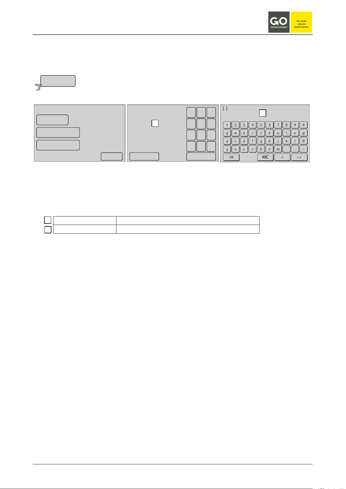
BlueBox
UDP settings
1 2 1
2
Appendix D - Example configuration BlueGate-Server
BlueBox settings: see also 8.2.1.1.5.1 UDP settings
Menu Internet settings 8.2.1.1.5
UDP settings
IP-Addr ess
Encryption on
09:19:39
10.07.10
91.221.182.141
1 2 3
4 5 6
708 9
Passw ord
<–
.
<
<–Ok
The current value is displayed.
see 6 The configuration data sheet:
BlueGate settings:
IP Address 91.221.182.141
Password BlueGate
xxxxx
Router settings:
For transmission of measurement data to the BlueGate Server the following port must be configured:
• Port 14112 UDP -> 91.221.182.141
For bidirectional communication with the BlueBox the following port must be configured:
• Port 14003 TCP <-> 91.221.182.141
For Windows-Software communication the following port must be configured:
• Port 14002 TCP <-> datagateway.go-sys.de
If a time server is connected to the BlueBox the following configuration is necessary:
• Port 37 TCP/UDP <-> Timeserver IP.
Note: If the internal network is not a Class A, B or C network then communication with the BlueBox is only
possible over: • Port 14110/TCP (SSL encrypted)
Unencrypted communication with the BlueBox is only possible from the following networks:
• 10.0.0.0/8 Class A network
• 172.16.0.0/12 Class B network
• 192.168.0.0/16 Class C network
GO Systemelektronik GmbH Faluner Weg 1 24109 Kiel Germany Tel.: +49(0)431-58080-0 Fax: -58080-11
www.go-sys.de info@go-sys.de
Page 74 / 77

BlueBox
Firmware version of
Appendix E - Update of the BlueBox firmware
Precondition is an operating LAN connection of the BlueBox.
Start FirmwareUpdate.exe on your PC.
the update
Click <Update>
• Select the tab <Default>.
• Enter the network password of the BlueBox.
(see 6 „The configuration data sheet“ item Network)
• enter the IP-Address of the BlueBox.
(see 6 „The configuration data sheet“ item Network)
Click <OK> Click <Yes>.
GO Systemelektronik GmbH Faluner Weg 1 24109 Kiel Germany Tel.: +49(0)431-58080-0 Fax: -58080-11
www.go-sys.de info@go-sys.de
The BlueBox reboots, you can close the window.
Wait until the BlueBox is ready.
The update is completed successfully.
Page 75 / 77

BlueBox
Appendix F - Opening a BlueBox housing
Shut down the BlueBox.
Disconnect the BlueBox from the power supply.
1. Remove the covers on both sides of the BlueBox.
2. Unscrew the four fixing screws.
3. Open the housing by hinging the cover from the front to the back.
In the cover there is the mainboard.
This work must be carried out by qualified persons using suitable tools.
GO Systemelektronik GmbH Faluner Weg 1 24109 Kiel Germany Tel.: +49(0)431-58080-0 Fax: -58080-11
www.go-sys.de info@go-sys.de
Page 76 / 77

BlueBox
11614
Appendix G - Status and error messages
Display Description
Parameter
The sensor sends data.
No data The sensor sends no data.
Wait The BlueBox is waiting for the first measured value.
[Parameter] Sensor warning, the measured value may be faulty.
Calc error AMS formula error
? Sensor In an AMS formula an unknown sensor is used.
Calc run
The computing time in an AMS formula has been exceeded
(for or while loop).
<min Parameter The minimum measured value as determined in AMS was underrunned.
>max Parameter The maximum measured value as determined in AMS was exceeded.
Com error Communication error with the sensor
ADC min The lower limit of the AD converter was underrunned.
ADC max The upper limit of the AD converter was exceeded.
Dev error Device error
At the multiple parameter display (see 8.1.2) error messages appear shortened.
GO Systemelektronik GmbH Faluner Weg 1 24109 Kiel Germany Tel.: +49(0)431-58080-0 Fax: -58080-11
www.go-sys.de info@go-sys.de
Page 77 / 77
 Loading...