

LTE Indoor CPE
Quick Start Guide
PN: 6061A4420323
WELCOME
TO THE LTE CPE
This document will serve as a quick start guide for LTE indoor
device. In this document, the LTE CPE will be called CPE for
short. Please read the following safety symbols carefully to
help you use the CPE safely and correctly.
Additional information
Optional methods or shortcuts for an action
Potential problems or conventions that need to be
specified
Package Contents
Please check the package contents before installation:
> LTE CPE
> Power adapter
If you find anything missing or damaged, please contact
your local service suppliers.
> Ethernet cable
> Quick Start Guide
GETTING STARTED
The figures provided in this document are just for
reference only, please refer to the actual which shall
govern.
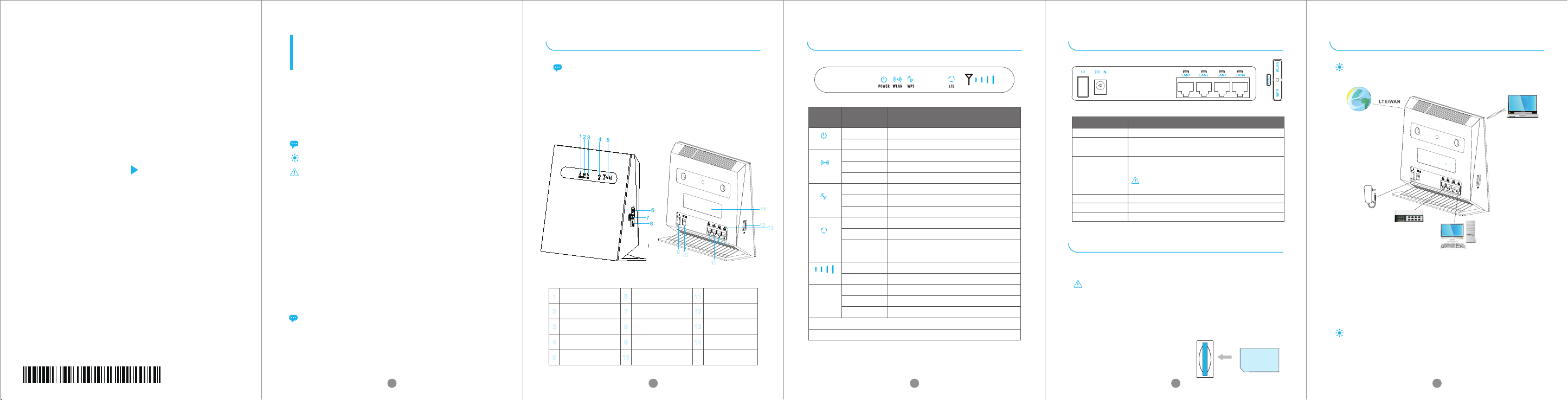
Equipment Appearance
9
10
11
1
POWER Indicator
2
Wi-Fi Indicator
3
WPS Indicator
4
LTE Status Indicator
5
LTE Signal Indicator
6
WPS Button
7
Reset Button
8
Wi-Fi Button
9
Power Switch
10
DC Jack
11
LAN Port
12
SIM Card Slot
13
LAN Indicator
14
Label
LED INDICATION
INTERFACE AND BUTTON
HARDWARE CONNECTION
The figure is just for reference only, please connect the
hardware according to your requirements.
LED
LED
Indicator
States
On
Off
POWER
On
Off
Wi-Fi
Blink
On
Off
14
12
13
WPS
Blink
Blue LED On
Red LED On
LTE
Blue LED
Blinking
On
SIGNAL
Off
On
LAN
Off
Blink
Special LED status 1: when upgrading firmware, WPS and Wi-Fi LED will blink.
Special LED status 1: when resetting CPE, All LED will be on except signal LED.
Description
Power supply normal
No power supply
Wi-Fi is enabled
Wi-Fi is disabled
Data is transferred through Wi-Fi
WPS is enabled
WPS is disabled
Wi-Fi access authentication in progress.
Resisted to LTE
Detecting no SIM card
Detected USIM Card, searching LTE network
Indictor LTE signal Strength.
No LTE signal
Ethernet connection is normal.
Ethernet connection is not established.
Ethernet interface data being transmitted.
Interface & button Description
DC IN
LAN1-LAN4
RESET
WLAN
WPS
SIM
DC power input port
Connet computer, switches (non PoE devices)
or other LAN devices
Press 1s to reboot device.
Press 10s and more, CPE will restore to factory mode.
You will lost user defined setting once you reset CPE.
So, be cautious to click Reset Button.
WLAN button
WPS PBC button
USIM Slot
SET UP THE HARDWARE
Insert SIM Card
If you want to remove the SIM card, please lightly press the
SIM card, the SIM card will pop out. Make sure the CPE is
turned off before you insert or remove your SIM card.
Otherwise, the CPE and SIM card may be damaged.
Please insert your SIM card as following:
Step 1 Connect the power adapter to the CPE.
Step 2 Power on CPE.
Step 3 Connect other devices.
·You can connect your computer or classic Switch via
Ethernet cable to LAN port.
·You can connect your laptop via Wi-Fi.
When you are using the CPE, you can adjust the position
and direction of CPE to get stronger LTE signal, judging
from the LTE signal LED indication.
1 2 3 4 5
SET UP CPE
Login the Web Management Page
Use a browser to login the web management page to
configure and manage the CPE.
Step 1 Connect the CPE properly.
Step 2 Launch Internet Explorer, enters http://192.168.1.1 in
the address bar, and press Enter.
IP address
XXXXXX
Step 3 Enter the user name and password, and login.
You can login to the web management page after the
password is verified.
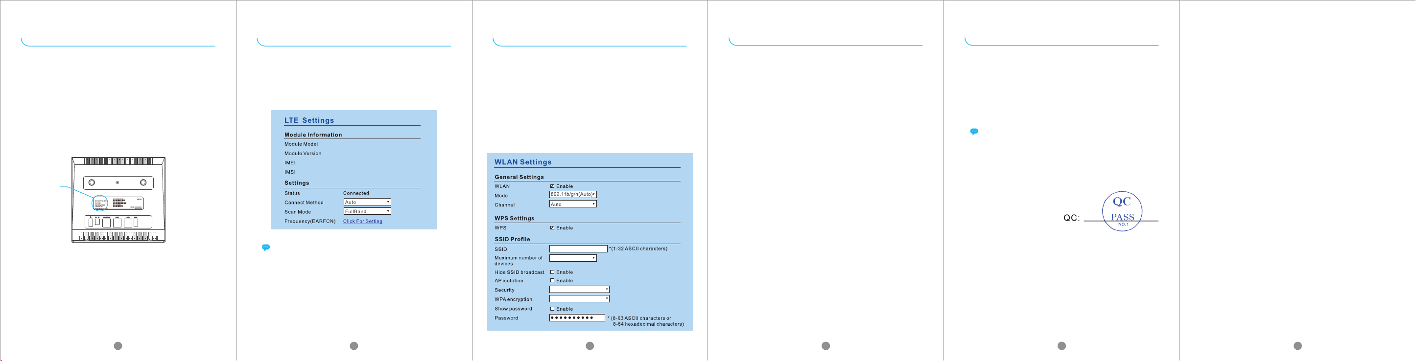
LTE SETTING
Step 1 Connect the CPE properly.
Step 2 Login to the web management page.
Step 3 Chose Network→LTE Setting.
Step 4 Set Connect Mode and Scan mode.
MLH9A11
4.2.2.0-30436-BYPASS-1.1.1
864537022230714
460680004200068
The default configuration are auto connect and scan full
band, if you want to connect the LTE network according to
your requirement, you can set the connect method as
manual, and just scan some specified band.
WI-FI SETTING
Step 1 Connect the CPE properly.
Step 2 Login the web management page.
Step 3 Chose Wi-Fi→WLAN Setting.
Step 4 In the General Settings area, set Wi-Fi to Enable, or
enable Wi-Fi with Wi-Fi button.
Step 5 In the Setting area, modify the SSID, such as “LTE-Router”.
Step 6 To ensure your data safety, it is recommended that you
change the default Wi-Fi password.
Step 7 Click Submit to save the configuration.
LTE-Router
32
WPA-PSK&WPA2-PSK
TKIP&AES
FAQs FAQs
The POWER indicator does not turn on.
·Make sure that the power cable is connected properly and
the CPE is powered on.
·Make sure that the power adapter is compatible with the CPE.
Fails to login the web management page.
·Make sure that the CPE is started.
·Verify that the CPE is correctly connected to the computer
through Wi-Fi or a network cable.
The CPE fails to search for the wireless network.
·Check that the power adapter is connected properly.
·Check that the CPE is placed in an open area that is far away
from obstructions, such as concrete or wooden walls.
·Check that the CPE is placed far away from household
electrical appliances that generate strong electromagnetic
field, such as microwave ovens, refrigerators, and satellite
dishes.
The power adapter of the CPE is overheated.
·The CPE will be overheated after being used for a long time.
Therefore, power off the CPE when you are not using it.
·Check that the CPE is properly ventilated and shielded from
direct sunlight.
The parameters are restored to default values.
·If the CPE is powered off unexpectedly while being configured,
the parameters may be restored to the default settings.
·After configuring the parameters, download the configuration
file to quickly restore the CPE to the desired settings.
If the problem persists, please contact authorized local
service suppliers.
This product has reached the standard of shipment inspection.
Notice
Some features of the product and its accessories described herein rely on
the software installed, capacities and settings of local network, and may
not be activated or may be limited by local network operators or network
service providers, thus the descriptions herein may not exactly match the
product or its accessories you purchase.
GOSUNCN reserves the right to change or modify any information or
specifications contained in this manual without prior notice or obligation.
FCC Regulations:
·This device complies with part 15 of the FCC Rules. Operation is subject to the
following two conditions: (1) This device may not cause harmful interference, and
(2) this device must accept any interference received, including interference that
may cause undesired operation.
· This equipment has been tested and found to comply with the limits for a Class
B digital device, pursuant to part 15 of the FCC Rules. These limits are designed
to provide reasonable protection against harmful interference in a residential
installation. This equipment generates, uses and can radiate radio frequency
energy and, if not installed and used in accordance with the instructions, may
cause harmful interference to radio communications. However, there is no
guarantee that interference will not occur in a particular installation. If this
equipment does cause harmful interference to radio or television reception, which
can be determined by turning the equipment off and on, the user is encouraged
to try to correct the interference by one or more of the following measures:
—Reorient or relocate the receiving antenna.
—Increase the separation between the equipment and receiver.
—Connect the equipment into an outlet on a circuit different from that to which the
receiver is connected.
—Consult the dealer or an experienced radio/ TV technician for help.
· Changes or modifications not expressly approved by the manufacturer could
void the user’s authority to operate the equipment.
FCC RF Radiation Exposure Statement
This equipment complies with FCC radiation exposure limits set forth for an
uncontrolled environment. To comply with FCC RF Exposure compliance
requirements, this grant is applicable to only Mobile Configurations. The
antennas used for the transmitter must be installed to provide a separation
distance of at least 20cm from all persons and must not be co-located or
operating in conjunction with any other antenna or transmitter.
The device is restricted to indoor use.
6 7 8
99 910 11
 Loading...