

Page 1

HARDWARE DEVELOPMENT GUIDE OF
MODULE
Version: V1.5
Date: 2018-04-28
LTE Module Series
ME3630 MINI-PCIE
Website: www.gosuncnwelink.com
E-mail: welink@gosuncn.com
Page 2
ME3630 mini-PCIE
ME3630 mini-PCIE
REVISION HISTORY
Version
Date
Description
V1.0
2016-05-27
1st published
V1.1
2016-07-06
Add the PID of ME3630_MP0 & MP1 in table 2-1,
update the pin in chapter 4.1
Update the Related Test data in chapter 7
V1.2
2016-08-24
Update the USIM_DET pin description, Figure 4-8 & Figure 4-9
Update the WAKEUP_IN & WAKEUP_OUT pins, Add 4.5 WAKEUP_IN signal, Figure 4-3 to Figure 4-6 ,
Table 4-3 to Table 4-4
V1.3
2017-02-16
Update the information of PIN 33
Update the picture of module
Add information of Evaluation Board in chapter 1.3
V1.4
2017-10-24
Update the pin20&22 description
Add information of ME3630-E&ME3630-J2A& ME3630-J2AS
V1.5
2018-04-28
Update the document format
Hardware Development Guide
All Rights reserved, No Spreading without GOSUNCN Permission III
Page 3
Hardware Development Guide
ME3630 mini-PCIE
ME3630 mini-PCIE
Abbreviations
Full Name
3GPP
Third Generation Partnership Project
AP
Another name of DTE
CHAP
Challenge Handshake Authentication Protocol
CE
European Conformity
CMOS
Complementary Metal Oxide Semiconductor
DCE
Data Communication Equipment
DL
Downlink
DTE
Data Terminal Equipment
EIA
Electronic Industries Association
EMC
Electromagnetic Compatibility
ESD
Electro-Static discharge
ESR
Equivalent Series Resistance
FDD
Frequency Division Duplex
GPIO
General-purpose I/O
LCC
Leadless Chip Carrier
LDO
Low-Dropout
LED
Light Emitting Diode
LTE
Long Term Evolution
ME
Mobile Equipment
MO
Mobile Origination Call
MT
Mobile Termination Call
MSB
Most Significant Bit
PC
Personal Computer
PCB
Printed Circuit Board
PDA
Personal Digital Assistant
PDU
Protocol Data Unit
PAP
Password Authentication Protocol
PPP
Point to Point Protocol
RTC
Real Time Clock
SMS
Short Messaging Service
SMT
Surface Mount Technology
SPI
Serial Peripheral Interface
TBD
To Be Determined
TCP
Transmission Control Protocol
ABOUT THIS DOCUMENT
A. Application Range
This document is the Product Technical Specification for the ME3630 GSM/CDMA/WCDMA/ TD-SCDMA/LTE TDD/LTE
FDD module. It defines the high level product features and illustrates the interface for these features. This document is
intended to cover the hardware aspects of the product, including electrical and mechanical.
B. Reading Note
The symbols below are the reading notes you should pay attention on:
: Warning or Attention
: Note or Remark
C. Purpose
This document provides the hardware solutions and development fundamentals for a product with the module. By
reading this document, the user can have an overall knowledge of the module and a clear understanding of the technical
parameters. With this document, the user can successfully fulfill the application and development of wireless Internet
product or equipment.
Besides the product features and technical parameters, this document also provides the product reliability tests and
related testing standards, RF performance indexes and a guide on the design of user circuits, to provide the user with a
complete design reference.
D. Abbreviations
Table below is a list of abbreviations involved in this document, as well as the English full names.
All Rights reserved, No Spreading without GOSUNCN Permission IV
Page 4

ME3630 mini-PCIE
ME3630 mini-PCIE
TIS
Total Isotropic Sensitivity
TRP
Total Radiated Power
TVS
Transient Voltage Suppressor
UART
Universal Asynchronous Receiver-Transmitter
UDP
User Datagram Protocol
UL
Up Link
USB
Universal Serial Bus
USIM
Universal Subscriber Identity Module
URC
Unsolicited result code
VIH
Logic High level of input voltage
VIL
Logic Low level of input voltage
VOH
Logic High level of output voltage
VOL
Logic Low level of output voltage
Hardware Development Guide
All Rights reserved, No Spreading without GOSUNCN Permission V
Page 5
Hardware Development Guide
ME3630 mini-PCIE
ME3630 mini-PCIE
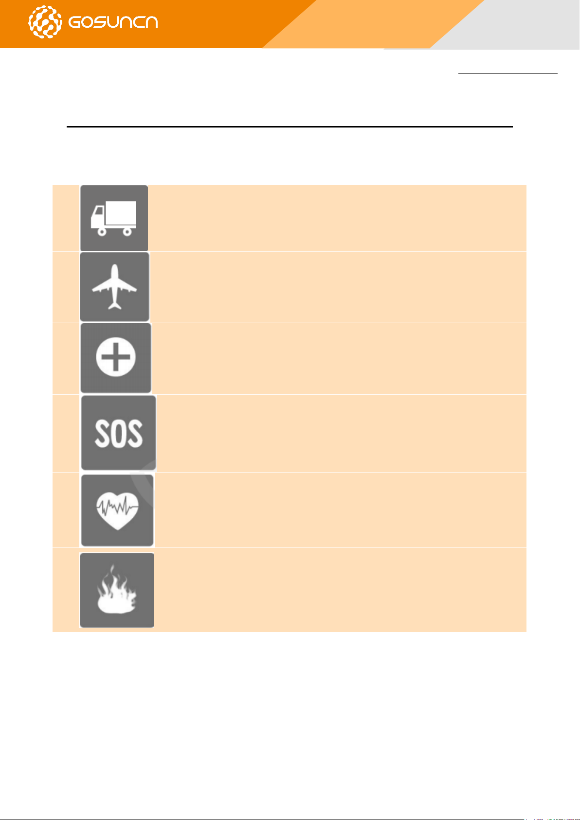
Full attention must be given to driving at all times in order to reduce the risk of an accident. Using a
mobile while driving (even with a hands free kit) cause distraction and can lead to an accident. You must
comply with laws and regulations restricting the use of wireless devices while driving.
Switch off the cellular terminal or mobile before boarding an aircraft. Make sure it switched off. The
operation of wireless appliances in an aircraft is forbidden to prevent interference with communication
systems. Consult the airline staff about the use of wireless devices on boarding the aircraft, if your device
offers a Airplane Mode which must be enabled prior to boarding an aircraft.
Switch off your wireless device when in hospitals or clinics or other health care facilities. These
requests are designed to prevent possible interference with sensitive medical equipment.
GSM cellular terminals or mobiles operate over radio frequency signal and cellular network and
cannot be guaranteed to connect in all conditions, for example no mobile fee or an invalid SIM card. While
you are in this condition and need emergent help, please remember using emergency call. In order to make
or receive call, the cellular terminal or mobile must be switched on and in a service area with adequate
cellular signal strength.
Your cellular terminal or mobile contains a transmitter and receiver. When it is on, it receives and
transmits radio frequency energy. RF interference can occur if it is used close to TV set, radio, computer or
other electric equipment.
In locations with potentially explosive atmospheres, obey all posted signs to turn off wireless devices
such as your phone or other cellular terminals. Areas with potentially explosive atmospheres including
fuelling areas, below decks on boats, fuel or chemical transfer or storage facilities, areas where the air
contains chemicals or particles such as grain, dust or metal powders.
SAFETY INFORMATION
The following safety precautions must be observed during all phases of the operation, such as usage, service or repair
of any cellular terminal or mobile incorporating ME3610 module. Manufacturers of the cellular terminal should send the
following safety information to users and operating personnel and to incorporate these guidelines into all manuals supplied
with the product. If not so, GOSUNCN does not take on any liability for customer failure to comply with these precautions.
All Rights reserved, No Spreading without GOSUNCN Permission VI
Page 6

Hardware Development Guide
ME3630 mini-PCIE
ME3630 mini-PCIE
CONTENTS
REVISION HISTORY ......................................................................................................... III
ABOUT THIS DOCUMENT .................................................................................................... IV
SAFETY INFORMATION ...................................................................................................... VI
CONTENTS ................................................................................................................ VII
FIGURES .................................................................................................................... IX
TABLES ...................................................................................................................... X
1 ABOUT THIS DOCUMENT ............................................................................................... 12
1.1 APPLICATION SCOPE ........................................................................................................................................................... 12
1.2 PURPOSE 12
1.3 EVALUATION BOARD ........................................................................................................................................................... 12
2 PRODUCT OVERVIEW ................................................................................................... 13
2.1 TECHNICAL PARAMETERS ..................................................................................................................................................... 14
2.2 BASEBAND FUNCTION ......................................................................................................................................................... 14
3 MECHANIC FEATURES .................................................................................................. 16
3.1 DIMENSIONS 16
3.2 HEAT-DISSIPATION DESIGN ................................................................................................................................................... 17
4 DESCRIPTION OF PINS .................................................................................................. 18
4.1 DEFINITION OF PIN SIGNALS ................................................................................................................................................ 18
4.1.1 PIN CONFIGURATION DIAGRAM ................................................................................................................................. 18
4.1.2 PIN DESCRIPTION .................................................................................................................................................... 18
4.2 FEATURE OF DIGITAL POWER LEVEL ........................................................................................................................................ 20
4.3 DESCRIPTION OF MAJOR PIN SIGNALS .................................................................................................................................... 21
4.4 POWER SUPPLY ................................................................................................................................................................. 21
4.4.1 GND INTERFACE ..................................................................................................................................................... 21
4.4.2 POWER SUPPLY ....................................................................................................................................................... 21
4.5 WAKEUP_IN SIGNAL ........................................................................................................................................................ 22
4.6 WAKEUP_OUT SIGNAL .................................................................................................................................................... 23
4.7 W_DISABLE_N SIGNAL .................................................................................................................................................... 24
4.8 RESET_IN SIGNAL ............................................................................................................................................................ 24
4.9 LED_WWAN_N SIGNAL ................................................................................................................................................... 25
4.10 (U)SIM CARD INTERFACE ................................................................................................................................ .................. 26
4.11 USB INTERFACE ............................................................................................................................................................... 27
4.12 UART INTERFACE ............................................................................................................................................................ 28
4.12.1 DESCRIPTION OF PINS ............................................................................................................................................ 28
All Rights reserved, No Spreading without GOSUNCN Permission VII
Page 7

Hardware Development Guide
ME3630 mini-PCIE
ME3630 mini-PCIE
4.12.2 ELECTRIC FEATURE ................................................................................................................................................. 28
5 POWER INTERFACE DESIGN GUIDELINE .................................................................................. 31
5.1 GENERAL DESIGN RULES ...................................................................................................................................................... 31
5.2 POWER SUPPLY REQUIREMENT ............................................................................................................................................. 31
5.3 CIRCUIT REQUIREMENTS OF POWER SUPPLY OUTPUT ................................................................................................................. 32
5.4 Recommended Power Reference Circuit ...................................................................................................................... 32
6 RF ANTENNA DESIGN GUIDE ........................................................................................... 34
6.1 ANTENNA INTERFACE .......................................................................................................................................................... 34
6.2 ANTENNA INDEXES ............................................................................................................................................................. 35
6.3 TEST METHODS FOR WHOLE-SET ANTENNA OTA ..................................................................................................................... 36
7 RELATED TEST .......................................................................................................... 37
7.1 OPERATING & STORAGE TEMPERATURE .................................................................................................................................. 37
7.2 GNSS TECHNICAL PARAMETERS ............................................................................................................................................ 37
7.3 ELECTROSTATIC DISCHARGE ................................................................ ................................................................ .................. 37
7.4 ME3630-C TEST .............................................................................................................................................................. 38
7.4.1 OPERATING CURRENT ............................................................................................................................................... 38
7.4.2 RF OUTPUT POWER ................................................................................................................................ ................. 38
7.4.3 RF RECEIVING SENSITIVITY ......................................................................................................................................... 39
7.5 ME3630-U TEST .............................................................................................................................................................. 39
7.5.1 CURRENT CONSUMPTION .......................................................................................................................................... 39
7.5.2 RF OUTPUT POWER ................................................................................................................................ ................. 40
7.5.3 RF RECEIVING SENSITIVITY ......................................................................................................................................... 40
7.6 ME3630-E TEST .............................................................................................................................................................. 41
7.6.1 CURRENT CONSUMPTION .......................................................................................................................................... 41
7.6.2 RF OUTPUT POWER ................................................................................................................................ ................. 41
7.6.3 RF RECEIVING SENSITIVITY ......................................................................................................................................... 42
7.7 ME3630-J2A TEST ........................................................................................................................................................... 42
7.7.1 CURRENT CONSUMPTION .......................................................................................................................................... 42
7.7.2 RF OUTPUT POWER ................................................................................................................................ ................. 43
7.7.3 RF RECEIVING SENSITIVITY ......................................................................................................................................... 43
All Rights reserved, No Spreading without GOSUNCN Permission VIII
Page 8

Hardware Development Guide
ME3630 mini-PCIE
ME3630 mini-PCIE
FIGURES
Figure 2–1 System Connection Diagram.............................................................................................. 15
Figure 3–1 PCI Express Mini Card Dimensions .................................................................................... 16
Figure 3–2 Thickness of PCI Express Mini Card ................................................................................... 16
Figure 4–1 PIN Distribution Diagram ................................................................................................... 18
Figure 4–2 GND Signal Connection ...................................................................................................... 21
Figure 4–3 WAKEUP_IN input sequence ............................................................................................. 22
Figure 4–4 Reference Connection Circuit of WAKEUP_IN Signal ........................................................ 22
Figure 4–5 Reference Connection Circuit of WAKEUP_OUT Signal ..................................................... 23
Figure 4–6 PIN1(WAKEUP_OUT) output sequence ............................................................................. 24
Figure 4–7 Reference Circuit Design of RESET_IN Signal ..................................................................... 25
Figure 4–8 Resetting signal .................................................................................................................. 25
Figure 4–9 Reference Design Circuit of LED_WWAN_N ...................................................................... 25
Figure 4–10 Connection Circuit of U(S)IM Card Signal ........................................................................ 26
Figure 4–11 USIM_DET pin logic .......................................................................................................... 27
Figure 4–12 Connection Circuit of USB Signal ..................................................................................... 28
Figure 4–13 Module Serial Port & AP Application Processor .............................................................. 29
Figure 4–14 The connection of UART and Standard RS-232-C interface ............................................. 29
Figure 4–15 UART level shifter from 1.8V to 3.3V ............................................................................... 30
Figure 5–1 Power Supply Current and Voltage Change under EDGE/GPRS ........................................ 32
Figure 5–2 Add storage capacitor to Module power supply terminal ................................................ 32
Figure 5–3 DC/DC Switching Power Supply ......................................................................................... 33
Figure 5–4 LDO Power Supply ............................................................................................................. 33
Figure 6–1 Antennal Interface Diagram .............................................................................................. 34
Figure 6–2 RF Interface Testing Console (U.FL-R-SMT1 (80) of HRS Corporation) .............................. 34
Figure 6–3 Testing Cable...................................................................................................................... 35
Figure 6–4 Profile Dimensions of RF antenna console ........................................................................ 35
Figure 6–5 The OTA test system of CTIA ............................................................................................. 36
All Rights reserved, No Spreading without GOSUNCN Permission IX
Page 9

Hardware Development Guide
ME3630 mini-PCIE
ME3630 mini-PCIE
TABLES
Table 2-1 Information of ME3630 mini-PCIE .............................................................................................................. 13
Table 2-2 Major Technical Parameters .................................................................................................................... 14
Table 4-1 PIN Definitions ......................................................................................................................................... 18
Table 4-2 Power Level of IO Interface ....................................................................................................................... 20
Table 4-3 WAKEUP_IN definition ......................................................................................................................... 22
Table 4-4 WAKEUP_OUT definition ..................................................................................................................... 23
Table 4-5 Definition and Description of W_DISABLE_N Signal ...................................................................................... 24
Table 4-6 Definition and Description of RESET_IN Signal ................................ ............................................................. 24
Table 4-7 Description of LED_WWAN_N Status .......................................................................................................... 25
Table 4-8 Definition and Description of USIM Card Signal ........................................................................................... 26
Table 4-9 Definition and Description of USB Interface ................................................................................................ 27
Table 4-10 Definition of UART Signal ......................................................................................................................... 28
Table 7-1 Product Temperature Range .................................................................................................................... 37
Table 7-2 GNSS Technical Parameters ....................................................................................................................... 37
Table 7-3 ESD ......................................................................................................................................................... 38
Table 7-4 Averaged standby DC power consumption [1] ............................................................................................. 38
Table 7-5 Averaged working current [1] ................................................................................................ .................... 38
Table 7-6 Averaged working current [2] .................................................................................................................... 38
Table 7-7 Conducted RF Output Power ..................................................................................................................... 38
Table 7-8 Conducted RF Receiving Sensitivity [1] ........................................................................................................ 39
Table 7-9 Conducted RF Receiving Sensitivity [2] ........................................................................................................ 39
Table 7-10 Averaged standby DC power consumption [1] ................................................................................... 39
Table 7-11 Averaged working current [1] ............................................................................................................. 39
Table 7-12 Averaged working current [2] ............................................................................................................. 40
Table 7-13 Conducted RF Output Power ............................................................................................................. 40
Table 7-14 Conducted RF Receiving Sensitivity Typical Value [1] ....................................................................... 40
Table 7-15 Conducted RF Receiving Sensitivity Typical Value [2] ....................................................................... 40
Table 7-16 Averaged standby DC power consumption [1] ................................................................................... 41
Table 7-17 Averaged working current [1] ............................................................................................................. 41
Table 7-18 Averaged working current [2] ............................................................................................................. 41
Table 7-19 Averaged working current [3] .................................................................................................................. 41
Table 7-20 Conducted RF Output Power ............................................................................................................. 41
Table 7-21 Conducted RF Receiving Sensitivity Typical Value [1] ....................................................................... 42
Table 7-22 Conducted RF Receiving Sensitivity Typical Value [2] ....................................................................... 42
Table 7-23 Conducted RF Receiving Sensitivity Typical Value [3] ....................................................................... 42
Table 7-24 Averaged standby DC power consumption [1] ................................................................................... 42
All Rights reserved, No Spreading without GOSUNCN Permission X
Page 10

Hardware Development Guide
ME3630 mini-PCIE
ME3630 mini-PCIE
Table 7-25 Averaged working current [1] ............................................................................................................. 42
Table 7-26 Averaged working current [2] ............................................................................................................. 43
Table 7-27 Conducted RF Output Power ............................................................................................................. 43
Table 7-28 Conducted RF Receiving Sensitivity Typical Value [1] ....................................................................... 43
Table 7-29 Conducted RF Receiving Sensitivity Typical Value [2] ....................................................................... 44
All Rights reserved, No Spreading without GOSUNCN Permission XI
Page 11

Hardware Development Guide
ME3630 mini-PCIE
ME3630 mini-PCIE
1 ABOUT THIS DOCUMENT
1.1 APPLICATION SCOPE
This document is applicable as the hardware development guide of GOSUNCN ME3630 mini-PCIe modules (hereinafter referred to as
the ME3630 module).
ME3630 mini-PCIE is one module of GOSUNCN mini-PCIE Series currently.
This document is intended for GOSUNCN customers to quickly understand ME3630 module interface specifications, electrical and
mechanical details.
1.2 PURPOSE
This document provides the hardware solutions and development fundamentals for a product with the module. By reading this
document, the user can have an overall knowledge of module and a clear understanding of the technical parameters. With this
document, the user can successfully fulfill the application and development of wireless 4G Internet product or equipment.
Besides the product features and technical parameters, this document also provides the product reliability tests and related testing
standards, service function implementation flow, RF performance indexes, and guide on the design of user circuits, to provide the
user with a complete design reference.
1.3 EVALUATION BOARD
In order to help you to develop applications with ME3630-PCIe, GOSUNCN supplies an evaluation board GE2015, RS-232 to USB
cable, USB data cable, power adapter, antenna and other peripherals to control or test the module. For details, please refer to the
related document [GOSUNCN GE2015 Dev Board User Guide].
All Rights reserved, No Spreading without GOSUNCN Permission 12
Page 12
Hardware Development Guide
ME3630 mini-PCIE
ME3630 mini-PCIE
ME3630 PCIe PID
RF support
RF Band
Transmit Frequency (TX)
Receive Frequency (RX)
U1A_MP0&U1A_MP
1(CAT4)
U1C_MP0&U1C_MP1
(CAT1)
LTE FDD
B2
1850 to 1910 MHz
1930 to 1990 MHz
B4
1710 to 1755 MHz
2110 to 2155 MHz
B5
824 to 849 MHz
869 to 894 MHz
B12
698 to 716 MHz
728 to 746 MHz
B17
704 to 716 MHz
734 to 746 MHz
WCDMA
B2
1850 to 1910 MHz
1930 to 1990 MHz
B5
824 to 849 MHz
869 to 894 MHz
E1C_MP0&E1C_MP1(
CAT4)
E1C_MP0&E1C_MP1(
CAT1)
LTE FDD
B1
1920 to 1980 MHz
2110 to 2170 MHz
B3
1710 to 1785 MHz
1805 to 1880 MHz
B7
2500 to 2570 MHz
2620 to 2690 MHz
B8
880 to 915 MHz
925 to 960 MHz
B20
832 to 862MHz
791 to 821 MHz
WCDMA
B1
1920 to 1980 MHz
2110 to 2170 MHz
B8
880 to 915 MHz
925 to 960 MHz
GSM
B3
1710 to 1785 MHz
1805 to 1880 MHz
B8
880 to 915 MHz
925 to 960 MHz
J2A_MP0&J2A_MP1(
Cat 4)
J2AS_MP0&J2AS_MP
1(Cat 1)
LTE FDD
B1
1920 to 1980 MHz
2110 to 2170 MHz
B3
1710 to 1785 MHz
1805 to 1880 MHz
B5
824 to 849 MHz
869 to 894 MHz
B7
2500 to 2570 MHz
2620 to 2690 MHz
B8
880 to 915 MHz
925 to 960 MHz
B18
815 to 830 MHz
860 to 875 MHz
B19
830 to 845 MHz
875 to 890 MHz
B21
1447.9 to 1462.9 MHz
1459.9 to 1510.9 MHz
WCDMA
B1
1920 to 1980 MHz
2110 to 2170 MHz
B5
824 to 849 MHz
869 to 894 MHz
2 PRODUCT OVERVIEW
ME3630 mini-PCIe is LTE wireless Internet modules with PCI Express Mini Card interface. It is widely applied to but not limited the
various products and equipment such as laptops, vehicle-mounted terminals, and electric devices, by providing data services.
Customer can choose the dedicated type based on the wireless network and function configuration. The following table shows the
entire radio band configuration of the ME3630 mini-PCIe series.
Table 2-1 Information of ME3630 mini-PCIE
All Rights reserved, No Spreading without GOSUNCN Permission 13
Page 13

Hardware Development Guide
ME3630 mini-PCIE
ME3630 mini-PCIE
B6
830 to 840 MHz
875 to 885 MHz
B8
880 to 915 MHz
925 to 960 MHz
B19
830 to 845 MHz
875 to 890 MHz
Name
Parameter Item
Specifications
Mechanical Feature
Dimensions
About 51mm×31mm×4.75 mm
Weight
About 10.0g
Form Factor
PCI Express Mini Card
Baseband
USIM/SIM
3V SIM card and 1.8V SIM card
USB Version
USB 2.0 HIGH SPEED, the data transfer rate can reach up to 480 Mbps.
Power supply
3.0~4.0V(Typ.3.3V/3.8V)
LED pin
Support
RF
Max. transmitter power
WCDMA Bands: 24 +1/-3dBm (Power Class 3)
GSM Band 8: 33±2dBm (Power Class 4)
GSM Band 3: 30±2dBm (Power Class 1)
LTE: +23dBm +2.7/-2.7dB (Power Class 3)
TD-SCDMA : 24 +1/-3dBm (Power Class 2)
Receiving sensitivity
WCDMA Band 1: ≤-106.7 dBm
GSM Band 3/ Band 8: ≤-102dBm
TD SCDMA Band34/39 : : ≤-107.3dBm
Main Antenna interface
Support, Provide Antenna Connector
Receive Diversity Antenna
Support, Provide Antenna Connector
GPS Antenna
Support, Provide Antenna Connector
2.1 TE CHNICAL PARAME TERS
The major features of ME3630 mini-PCIE can be described from the aspects of mechanic feature, base band, radio frequency,
technical standard and environment feature. The table below is a list of the major technical parameters and features supported by
products.
Table 2-2 Major Technical Parameters
2.2 BASE BAND FUNC TION
The baseband part of module mainly includes the following signal groups: USB signal, SIM card signal, Analog Voice signal,
WAKEUP_OUT wakeup (PC) signal, working status indicator signal WWAN_LED_N, RF switch control signal W_DISABLE_N, whole-set
reset signal PERST_N, power and grounding. Meanwhile, the product also provides the main antenna, GPS antenna and the Dx
antenna. Figure below is a system connection diagram.
All Rights reserved, No Spreading without GOSUNCN Permission 14
Page 14

ME3630 mini-PCIE
ME3630 mini-PCIE
Figure 2–1 System Connection Diagram
PCI Express Mini Card
wireless Internet-access
module
Module system-side interface
USB
USIM
UART
WAKEUP_OUT
W_DISABLE_N
WWAN_LED_N
PERST_N
Main
GPS
Div
Hardware Development Guide
All Rights reserved, No Spreading without GOSUNCN Permission 15
Page 15

Hardware Development Guide
ME3630 mini-PCIE
ME3630 mini-PCIE
3 MECHANIC FEATURES
3.1 DIMENSIONS
The product employs the standard PCI Express Mini Card interface type, with its dimensions designed according to F2 type. Figure
3-1 illustrates the dimensions and slot compatibility of PCI Express Mini Card (Unit: mm).
Figure 3–1 PCI Express Mini Card Dimensions
Figure 3–2 Thickness of PCI Express Mini Card
All Rights reserved, No Spreading without GOSUNCN Permission 16
Page 16

Hardware Development Guide
ME3630 mini-PCIE
ME3630 mini-PCIE
3.2 HEAT-DISSI PAT ION DESIGN
The heat-dissipation design of ME3630 mini-PCIE strictly complies with PCI Express Mini Card Electromechanical Specification
Revision 1.2, October 26 2007. The heat sources are evenly distributed, and the product has a very excellent heat-dissipation design.
To ensure that the product performance is fully played out, it is recommended to design the main board as follows:
Locate the module far away from the switch power and high-speed signal cable as much as possible. Well protect the wiring of
the interference sources.
The antenna, and the coaxial cable connecting the network cable and the antenna, cannot be located close the interference
sources.
Do not locate the module close to devices with large heat dissipation, such as CPU, south bridge, etc. The high temperature will
affect the RF performance.
All Rights reserved, No Spreading without GOSUNCN Permission 17
Page 17

Hardware Development Guide
ME3630 mini-PCIE
ME3630 mini-PCIE
PIN
ME3630_MP0
PCIE Signal
ME3630_MP1
PCIE Signal
Pin Voltage
(VDD_PX)
I/O
Description of Pins
1
WAKEUP_OUT
NC
O
MP0: Module wakes up external AP,need to pull up externally.
Active low
MP1: Not connected
2
V_MAIN
V_MAIN
I Power supply
3.0~4.0V(Typ.3.3V/3.8V)
3
NC
NC
Not connected
4
GND
GND
Ground
5
NC
NC
Not connected
6
NC
NC
Not connected
7
NC
NC
Not connected
4 DESCRIPTION OF PINS
4.1 DEFINITION OF PIN SIGN ALS
4.1.1 PIN CONFIGURATION DIAGRAM
The products are designed according to PCI Express Mini Card Electromechanical Specification Revision 1.2, October 26 2007. Figure
below illustrates the PIN sequence, and Table 4-2 describes the detailed PIN definitions.
Figure 4–1 PIN Distribution Diagram
4.1.2 PIN DESCRIPTION
The table below descript the pins of module ME3630_MP0 and ME3630_MP1, there is several difference of PIN definition between
this two PID.
Table 4-1 PIN Definitions
All Rights reserved, No Spreading without GOSUNCN Permission 18
Page 18

Hardware Development Guide
ME3630 mini-PCIE
ME3630 mini-PCIE
8
USIM_VCC
USIM_VCC
1.8V/3V
O
Power supply for USIM
9
GND
GND
Ground
10
USIM_DATA
USIM_DATA
1.8V/3V
I/O
USIM data
11
UART_RXD
1.8V
1.8V I MP0:UART Receive Data
MP1: Reference Voltage
Output current must be lower than 10mA
12
USIM_CLK
USIM_CLK
3V O USIM clock
13
UART_TXD
NC
1.8V O UART Transmit Data
14
USIM_RST
USIM_RST
1.8V/3V
O
USIM reset
15
GND
GND
Ground
16
UART_DSR
UART_DSR
1.8V O Module set ready
17
UART_RI
UART_RI
1.8V O UART Ring Indicator
18
GND
GND
Ground
19
WAKEUP_IN
WAKEUP_IN
1.8V External AP to set the module into sleep or wake up the module
from sleep
20
W_DISABLE_N
W_DISABLE_N
I Active low signal for RF disable (Airplane mode)
21
GND
GND
Ground
22
RESET_IN
RESET_IN
I Module’s reset signal, active low
23
UART_CTS
UART_RX
1.8V I MP0:UART Clear to Send
MP1: UART Receive Data
24
V_MAIN
V_MAIN
3.3V I Power supply
3.0~4.0V(Typ.3.3V/3.8V)
25
UART_RTS
UART_RTS
1.8V O UART Request to send
26
GND
GND
Ground
27
GND
GND
Ground
28
1.8V
1.8V
Reference Voltage
Output current must be lower than 10mA
29
GND
GND
Ground
30
NC
NC
Not connected
31
UART_DTR
UART_TXD
1.8V I MP0:UART DTE get ready
MP1 : UART Transmit Data
32
NC
WAKEUP_OUT
MP0:Not connected
MP1 : Module wakes up external AP,need to pull up externally.
Active low
33
UART_DCD
RESET_IN
1.8V MP0: UART Carrier detects, Output.
MP1: Module’s reset signal, Input pin. active low, the low level
All Rights reserved, No Spreading without GOSUNCN Permission 19
Page 19

Hardware Development Guide
ME3630 mini-PCIE
ME3630 mini-PCIE
input must be higher than 50mV.
34
GND
GND
Ground
35
GND
GND
Ground
36
USB_DM
USB_DM
USB data signal D-
37
GND
GND
Ground
38
USB_DP
USB_DP
I/O
USB data signal D+
39
V_MAIN
V_MAIN
3.3V I Power supply
3.0~4.0V(Typ.3.3V/3.8V)
40
GND
GND
Ground
41
V_MAIN
V_MAIN
3.3V I Power supply
3.0~4.0V(Typ.3.3V/3.8V)
42
LED_WWAN_N
LED_WWAN_N
O
LED pin, Work status indication
43
GND
GND
Ground
44
USIM_DET
USIM_DET
1.8V O SIM card Detect, need to pull up externally. When detect high
level SIM card is un-existed, detect low SIM card is existed.
45
NC
NC
46
NC
NC
Not connected
47
NC
NC
48
NC
NC
Not connected
49
NC
NC
50
GND
GND
Ground
51
NC
NC
52
V_MAIN
V_MAIN
3.3V Power supply
3.0~4.0V(Typ.3.3V/3.8V)
Parameter
Description
Minimum
Maximum
Unit
VIH
High-level input voltage
0.65*VDD_PX
VDD_PX+0.3
V
VIL
Low-level input voltage
-0.3
0.35*VDD_PX
V
VOH
High-level output voltage
VDD_PX-0.45
VDD_PX
V
NOTE: “NC” indicates Not Connected.
4.2 FEATURE OF DIGITAL POW ER LEVEL
The following table shows logic level specifications used in the module’s interface circuits:
All Rights reserved, No Spreading without GOSUNCN Permission 20
Table 4-2 Power Level of IO Interface
Page 20

Hardware Development Guide
ME3630 mini-PCIE
ME3630 mini-PCIE
VOL
Low-level output voltage
0
0.45
V
NOTE:
1. High and low level of input voltage must locate within the ranges specified in the above table.
2. High and low level of external interface signals must match interface level of this product.
3. VDD_PX=1.8V/3.3V, which indicates the pin voltage, the concrete value please refer to the table 4-1
4.3 DESCRIP TIO N O F MAJOR PIN SIG NAL S
The following section describes the common pins of module, including the functions of each interface, its default input and output
features, and its matched circuits. The user can reasonably design the application circuits on the system board according to the PIN
descriptions.
The module provides the interfaces/signals as follows:
Power and Reset Interface
UART Interface
USIM Card Interface
USB2.0 interface
Antenna Interface
LED Interface
WAKEUP_OUT & W_DISABLE_N Signal
4.4 POWER SUPPLY
The host provides power to the module through multiple ground and power pins as summarized in 4.4.1 and 4.4.2. The host must
provide safe and continuous power at all times; the module does not have an independent power supply.
4.4.1 GND INTERFACE
The GND signal (PIN No: 4/9/15/18/21/26/27/29/34/35/37/40/43/50). This is the power grounding and signal grounding of module.
They need to be all connected to the ground level of system boards. The incomplete connection of GND signals will affect the
performance of the module.
Figure 4–2 GND Signal Connection
4.4.2 POWER SUPPLY
The 3.3Vaux signal (PIN No: 2/24//39/41/52, Power Interface). This is the positive signal of 3.3V/3.8V power, and is also the input
signaling of module’s power. The power supply is recommended to be within the range of 3.0~4.0V(Typ.3.3V/3.8V)
All Rights reserved, No Spreading without GOSUNCN Permission 21
Page 21

Hardware Development Guide
ME3630 mini-PCIE
ME3630 mini-PCIE
Signal
No.
I/O
Description of Pins
Note
WAKEUP_IN
19
DI
Input signal
1.8V domain, drop-down default. it triggers
the action only when level change
Rising edge wake up module; Falling edge modules
can enter sleep.
WAKEUP_IN
High
Low
Module state
Operating State Sleep state
High
Operating State
4.5 WAKEUP_IN SIG NAL
WAKEUP_IN pin is the authorization signal of module entering sleep state.
If the signal is pulled up to high level (1.8 V), module cannot enter sleep mode. If this pin is not connected, it will keep in low level by
default.
Table below shows the definition of the WAKEUP_IN signal.
Table 4-3 WAKEUP_IN definition
Figure 4–3 WAKEUP_IN input sequence
Figure 4–4 Reference Connection Circuit of WAKEUP_IN Signal
NOTE:
The resistors in Figure above is only the recommended value and they need to adjust according to the actual situation.
There is anti-shake design with pin WAKEUP_IN internal, external processor need to pull-up or pull-down the pin last for
at least 500ms.
All Rights reserved, No Spreading without GOSUNCN Permission 22
Page 22

Hardware Development Guide
ME3630 mini-PCIE
ME3630 mini-PCIE
Signal
No.
I/O
Description of Pins
Note
WAKEUP_OUT
1
DO
MP0:
Module wakes up
external AP, need to pull
up externally. Active low
This pin outputs a high-level voltage by
default. When a wake-up source arrives,
such as new SMS, call or network data
arrives, this pin outputs a low-level-voltage
pulse lasting for 1s.
WAKEUP_OUT
4.6 WAKEUP_OUT SI GNA L
The WAKEUP_OUT signal (PIN No. 1) is an output signal, active low. This signal is used for module to wake up the host. It is
designed as an OC gate, so it should be pulled up by the host and it is active-low. Figure 4-3 illustrates the reference connection
circuit of WAKEUP_OUT signal.
Table 4-4 WAKEUP_OUT definition
Figure 4–5 Reference Connection Circuit of WAKEUP_OUT Signal
NOTE:
The resistors in Figure above is only the recommended value and they need to adjust according to the actual situation.
Do not directly connect this signal to the positive end of the power supply.
When there is a call/SMS received by the module, it will output the level shown as the figure below through WAKEUP_OUT pin to
wake the host.
All Rights reserved, No Spreading without GOSUNCN Permission 23
Page 23

Hardware Development Guide
ME3630 mini-PCIE
ME3630 mini-PCIE
Module status
Operating state
Sleep state
low
High
WAKEUP_OUT
1s
W_DISABLE_N
Module Status
‘1’
RF is enabled.
‘0’
RF is disabled.
RESET_IN
Module Status
‘1’
Module is in the normal working status.
‘0’ and t≥1s
RF is in the OFF mode, Module will reset.
Figure 4–6 PIN1(WAKEUP_OUT) output sequence
4.7 W_DISABLE_N SIGN AL
The W_DISABLE_N signal (PIN No: 20) -- Active low, pulled up internally, input from a hardware switch to the module that disables
the main RF radio. Table below describes its control logic.
Table 4-5 Definition and Description of W_DISABLE_N Signal
The reference circuit design of W_DISABLE_N signal can refer to the interface of RESET_IN signal.
NOTE: Do not directly connect this signal to the positive end of the power supply.
4.8 RESET_IN SIGNAL
The RESET_IN signal (PIN No: 22) is the system reset signal of the module, active low. Table below illustrates its control logic. Figure
below shows that pull down the reset key (RESET_IN) more than 1s will reset the module.
NOTE: Do not directly connect this signal to the positive end of the power supply.
Table 4-6 Definition and Description of RESET_IN Signal
All Rights reserved, No Spreading without GOSUNCN Permission 24
Page 24

ME3630 mini-PCIE
ME3630 mini-PCIE
Figure 4–7 Reference Circuit Design of RESET_IN Signal
1s
1
0
PON_RESET_N
Module
LED_WWAN_N Signal Status
Status of Module
Expected Indicator Status
High power level ‘1’, 3.3V
Not registered to the network
The indicator is OFF.
Low power level ‘0’, 0V
Registered to the network
The indicator is always on.
Figure 4–8 Resetting signal
Hardware Development Guide
4.9 LED_WWAN_N SI GNA L
The LED_WWAN_N signal (PIN No: 42, Status Indication PIN) is the signal indicating the current working status of the module, which
is generated by the module. The LED indicator need to be equipped on the system side for this feature, and the LED indicator is ON
when this signal generates the low power level. Table below illustrates the indicator status, and Figure below illustrates the
reference circuit design of LED_WWAN_N signal.
Table 4-7 Description of LED_WWAN_N Status
Figure 4–9 Reference Design Circuit of LED_WWAN_N
All Rights reserved, No Spreading without GOSUNCN Permission 25
Page 25

Hardware Development Guide
ME3630 mini-PCIE
ME3630 mini-PCIE
PIN
Signal Definition
Signal Description
8
USIM_VCC
USIM card power, output by Module
10
USIM_DATA
USIM card DATA signal, two-way signal
12
USIM_CLK
USIM card clock signal, output by Module
14
USIM_RST
USIM card reset signal, output by Module
44
USIM_DET
SIM card Detect, need to pull up externally. When detect high level SIM card is
un-existed, detect low SIM card is existed.
Module
(Modem)
USIM
Card
Connecter with
detect pin
4.10 (U)SIM CARD IN TER FACE
SIM -- supported through the interface connector. The USIM connector must be placed on the host device for this feature. The signal
group of USIM card is as follows: PIN No: 8/10/12/14). Table below is a detailed description of each signal. Voltage levels over th is
interface comply with 3GPP standards.
Table 4-8 Definition and Description of USIM Card Signal
To comply with the requirements of 3GPP TS 51.010-1 and EMC authentication, it is recommended to place (U)SIM card console
close to the (U)SIM card interface, to prevent the wiring from being too long, which might seriously distort the waveform and thus
affect the signal integrity.
The following Figure shows the reference design of as well as the recommended circuit of the USIM card. ESD circuit protection and
UIM_DATA pull-up have been added in the board of ME3630 mini-PCIE.
Figure 4–10 Connection Circuit of U(S)IM Card Signal
All Rights reserved, No Spreading without GOSUNCN Permission 26
Page 26

ME3630 mini-PCIE
ME3630 mini-PCIE
4.11 USB INTE RFACE
Name
Pin
Description
USB_DM
36
USB data negative
USB_DP
38
USB data positive
Hardware Development Guide
Figure 4–11 USIM_DET pin logic
The module has a high-speed USB2.0 interface, which supports both the full-speed (12 Mbps) mode and the high-speed (480 Mbps)
mode. It is connected to the system board side by the PIN 36 (USD_DM) and 38 (USB_DP). The USB interface is the path for
communication between the host and module and it is mainly used in data transmission.
Table 4-9 Definition and Description of USB Interface
The USB interface complies with the USB2.0 specifications and the electric features. When designing the host device, careful PCB
layout practices must be followed. USB_DP, USB_DM should be wired strictly according to the differential mode, and the length
difference between the two cables should be restricted within 1mm.
It is important to route the USB signal traces as differential pairs with total grounding. The impedance of USB differential trace is
90ohm.
Pay attention to the influence of junction capacitance of ESD component on USB data lines. Typically, the capacitance value should
be less than 2pF.
All Rights reserved, No Spreading without GOSUNCN Permission 27
Page 27

ME3630 mini-PCIE
ME3630 mini-PCIE
Figure 4–12 Connection Circuit of USB Signal
Signal Name
I/O
Description
UART1_RX
DI
UART port RX receive data
UART1_TX
DO
UART port TX transmit data
UART1_DSR
DO
Data is ready
UART1_RI
DO
Ringtone indicator
UART1_CTS
DI
UART port CTS clear to send
UART1_RTS
DO
preparing to receive
UART1_DTR
DI
Data terminal is ready
UART1_DCD
DO
Carrier detection
NOTE: The differential impedance should be controlled within 90ohm.
Hardware Development Guide
4.12 UART INTER FACE
4.12.1 DESCRIPTION OF PINS
The wireless module supports the full UART interface with flow control function, which complies with the RS-232 interface protocol.
This UART port supports the programmable data width; programmable data stop bit and programmable parity check, and has an
independent TX and RX FIFOs (512 bytes for each). For the normal UART application (non-Bluetooth), the maximum baud rate is
230400bps, and the default baud rate is 115200bps. The PINs are defined as shown in Table below.
NOTE: This chapter is only used for PID MP0.
Table 4-10 Definition of UART Signal
4.12.2 ELECTRIC FEATURE
It is recommended that this UART interface be kept during the design and the testing point be reserved for the software
interconnection. If the module’s UART interface is connected with the host device, and the UART PWL of host device matches wi th
1.8V, the connection mode is as shown in figure below.
All Rights reserved, No Spreading without GOSUNCN Permission 28
Page 28

ME3630 mini-PCIE
ME3630 mini-PCIE
Figure 4–13 Module Serial Port & AP Application Processor
UART1_RX
UART1_TX
UART1_CTS
UART1_RTS
UART1_DTR
UART1_DSR
UART1_DCD
UART1_RI
TXD
RXD
RTS
CTS
DTR
DSR
DCD
RING
Module Application
DCE
DTE
TTL-
RS232
level
translator
SP3238
MAX3238
Module
1.8V
-TTL
level
translator
NLSX5014MUTAG
UART1_DCD
UART1_DSR
UART1_TX
UART1_CTS
UART1_RX
UART1_RFR
UART1_DTR
UART1_RI
GND
RS232_DCD
RS232_DSR
RS232_TXD
RS232_CTS
RS232_RXD
RS232_RTS
RS232_DTR
RS232_RI
GND
1
2
3
4
5
6
7
8
9
User Board
Female DB9
Note:UART1_RFR is equal to UART1_RTS.
Hardware Development Guide
If it does not match the PWL of AP interface, it is recommended to add the PWL conversion circuit. Otherwise, it might cause
unstable com ports because the level is not matched or cause damage to the module because it is at high level for long time. The
connection of module UART port and standard RS-232-C interface can be through the chip like class 232. The design involves the
transformation of TTL level and EIA level. We recommend to use the chip of NLSX5014MUTAG. If using the 2-wire serial bus interface,
MAX3232 is recommended, and if using the 8-wire serial bus interface, SP3238 or MAX3238 is recommended. The connection mode
is as shown in Figure below.
If customer wants to connect a 3.3V application system, a level shifter should be used. The following figure shows the reference
design. The diode in this Figure is Schottky diode (forward voltage drop is 0.3V). If you select other diodes, please select one with
lower forward voltage drop to make sure UART_RXD is below the threshold when inputting low level.
All Rights reserved, No Spreading without GOSUNCN Permission 29
Figure 4–14 The connection of UART and Standard RS-232-C interface
Page 29

Hardware Development Guide
ME3630 mini-PCIE
ME3630 mini-PCIE
VCC_EXT
Module(DCE)
UART1_TX(1V8)
33.2K 1K
VCC(3.3V)
AP(DTE)
UART_RXD(3V3)
22pF
10K
100pF
VCC_EXT
Module(DCE)
UART1_RX(1V8)
AP(DTE)
UART_TXD(3V3)
NOTE:
The resistors in Figure below is only the recommended value and they need to adjust according to the actual situation.
Figure 4–15 UART level shifter from 1.8V to 3.3V
All Rights reserved, No Spreading without GOSUNCN Permission 30
Page 30

Hardware Development Guide
ME3630 mini-PCIE
ME3630 mini-PCIE
5 POWER INTERFACE DESIGN GUIDELINE
This chapter provides the power supply requirements, general design rules. Users can design the power supply of module to achieve
stable and well working performance according to this document.
5.1 GE NERAL DESIGN RULE S
When the module is used for different external applications, pay special attention to the design for the power supply.
In the process of peripheral circuit designing, users of this Module product should ensure that the external power supply cir cuit is
capable of providing sufficient power supply capacity firstly, and control the supply range between 3.0~4.0V(Typ.3.3V/3.8V) strictly. If
the value above module voltage range, it will lead the main chip burned, while below required voltage range, it will affect t he RF
circuit’s performance or cause shutdown and restart occurred. For the design of high-speed USB signal lines, it requires to control the
differential impedance at 90ohm. The voltage design of external circuit interfaces should match that of the module PINs, and the
detailed value can be got in Chapter 4. The module product has a good RF indicator; customers can refer to Chapter 6 in the process
of antenna circuit designing.
5.2 POWER SUPPLY REQ UIREMENT
The power supply of PCIE Type module is usually recommended to be within the range of 3.0~4.0V(Typ.3.3V/3.8V). According to the
requirement of mobile terminal device, the power supply voltage of module is 3.3V under normal working condition.
If the network is in poor situation, the antenna will transmit at the maximum power, and the transient maximum peak current can
reach as high as 2.3A. So the power supply capacity for peak current on the main board needs to be above 2.3A to satisfy the
requirement of module peak current; and the average current on the system side needs to be above 2.0A. Meanwhile, consider the
voltage drop of power supply on the side of main board. If the network is in a poor situation or under 2G, the module peak cu rrent
will be great. Therefore the power supply has to be designed in order to withstand with these current peaks without big voltage
drops; this means that both the electrical design and the board layout must be designed for this current flow. If the layout of the PCB
is not well designed a strong noise floor is generated on the ground and the supply; and exceptions such as restart of the module
may occur.
The peak current of module under the GSM BURST mode is different due to the differences in actual network environments. And i ts
transient current under different powers will be various as well. The greater the power is, the greater the transient current is. The
network quality also directly affects the work current of the module. If the network is in well situation, the peak work current on the
module will be small. But if the network is in poor situation, its peak current will be great as shown in Figure 5-1 (when the module
works under the EDGE/GPRS Time Slot (2-high 6-low) and CLASS10). If the module works under the 2-high work Time Slot, it requires
greater current, and the voltage drop will occur accordingly.
All Rights reserved, No Spreading without GOSUNCN Permission 31
Page 31

ME3630 mini-PCIE
ME3630 mini-PCIE
Figure 5–1 Power Supply Current and Voltage Change under EDGE/GPRS
0
t/ms
0
0
Unit: 200mA/cell
Unit: V/cell
Voltage
Current
EDGE/GPRS TS
2-high 6-low
CLASS10
3.462ms1.154ms
(577us/cell)
200mA
200mA
200mA
200mA
200mA
200mA
1V
2V
3V
3.6V
DC3.3V
VDD_3V3
0.47uF
22uF
330uF
2200uF
330uF
C1
C2
C3
C4
C5
C6
330uF
Hardware Development Guide
5.3 CIRC UIT RE QUIREMENT S O F POWE R SUPP LY OUTPUT
Requirement:
The electrical design for the Power supply should be made ensuring it will be capable of a peak current output of at least 2.5 A.
The average current supplied by the system host needs to be above 2.0A.
When designing the PCB line, the power cable on the system board should be thick enough, and should form a good reflux with the
ground.
In the power supply circuit design, the user needs to add the large storage capacitor on the kilo level, to guarantee the transient
power supply capability as well as the system instantaneous power capacity, and to prevent the module from resetting and shutting
down caused by voltage fluctuation.
Figure 5–2 Add storage capacitor to Module power supply terminal
5.4 Recommended Power Reference Circuit
Option one:
Use DCDC switching power supply and large storage capacitor on the kilo level to ensure the normal operation of the RF power
amplifier to withstand these current peaks without big voltage drops.
Advantage:
All Rights reserved, No Spreading without GOSUNCN Permission 32
Page 32

Hardware Development Guide
ME3630 mini-PCIE
ME3630 mini-PCIE
Vin=5V
Vout=3.3V
3V3
Can provide well transient current under 2G weak signal environment to satisfy modules requirements, to prevent device shutdown
and ports re-enumeration as a consequence of the supply voltage drop.
The over-current capability requirement of DC/DC switching power supply need to be above 3A, for example, ZI1153, AAT2138 and
so on.
Input voltage range of ZI1153 is: 2.5~5.5V,output voltage range of ZI1153 is from 0.6V to VIN( input voltage).
Input voltage range of AAT2138is: 2.7~5.5V,output voltage range of AAT2138is from 3.3~5.5V.
As shown in the Figure below, use DC/DC switching power supply ZI1153 as the buck chip. Place a tantalum capacitor of 330μF at the
input of the chip. Place a 2200UF capacitor or place several 330μF tantalum capacitors in parallel. This circuit fully meets the module
power requirements. (If the user’s PCB size is limited, the output of buck chip can place three more 330μF tantalum capacitors of
which the total capacity is more than 1000μF)
Figure 5–3 DC/DC Switching Power Supply
Option two:
Use LDO as the buck chip. The over-current capability of LDO is above 3A. As the poor transient response of linear regulator, large
capacitors should be placed at the input and output of LDO. The output of LDO, place a capacitors above 2000μF. The reference
power supply circuit design with LDO is as shown in Figure below.
Figure 5–4 LDO Power Supply
NOTE: The resistor and capacitor in the Figure 5-3 and Figure 5-4 is just for example, the use need to choose the proper ones
according to the output voltage level.
All Rights reserved, No Spreading without GOSUNCN Permission 33
Page 33

Hardware Development Guide
ME3630 mini-PCIE
ME3630 mini-PCIE
6 RF ANTENNA DESIGN GUIDE
The antenna connection is one of the most important aspect in the full product design as it strongly affects the product
overall performances, hence read carefully and follow the requirements and the guidelines for a proper design.
6.1 ANTENNA IN TERFAC E
The Mini PCIE adapter is equipped with three RF antenna connectors: the main antenna interface, GPS antenna interface
and Diversity antenna interface, as shown in Figure 6-1. The antennal connector employs the U.FL-R-SMT1 (80) RF console
from HRS Corporation, as shown in Figure 6-2. For the specified cables on the RF interface, it is recommended to use
U.FL_LP_088 of HRS Corporation, as shown in Figure 6-3. Profile Dimensions of RF antenna console is shown in Figure 6-4
(Unit: mm).
For more information about mating connectors visit the website http://www.hirose-connectors.com/.
Figure 6–1 Antennal Interface Diagram
Figure 6–2 RF Interface Testing Console (U.FL-R-SMT1 (80) of HRS Corporation)
All Rights reserved, No Spreading without GOSUNCN Permission 34
Page 34

ME3630 mini-PCIE
ME3630 mini-PCIE
Figure 6–3 Testing Cable
Figure 6–4 Profile Dimensions of RF antenna console
Hardware Development Guide
6.2 ANTENNA IN DEX ES
The module supports the AGPS/GPS function, so the system equipment needs to add the GPS antenna. The design of GPS
antenna is consistent with that of the main antenna, and its efficiency can be 3dB lower. The isolation between the main
antenna and the diversity antenna is required to be greater than 12dB. The difference between Rx TIS and the TIS of main
antenna should be within 6dB.
The antenna index is divided into the Passive index and Active index. The Passive index includes S11, efficiency, gains,
radiation pattern and polarity, which can be used as the parameter measuring the performance of the antenna itself. The
Active index is also called the OTA index, including TRP (all-round radiation power), TIS (all-round receiving sensitivity),
radiation pattern, which is an important index measuring the radiation performance of the whole set (including the antenna,
module, main board).
All Rights reserved, No Spreading without GOSUNCN Permission 35
Page 35

Hardware Development Guide
ME3630 mini-PCIE
ME3630 mini-PCIE
6.3 TE ST ME THODS FOR WHOLE -SE T ANTENNA OTA
Figure 6-5 is the diagram of OTA test system of CTIA. The system is mainly composed of test chamber, high-precision
positioning system and its controller, Windows based PC running test software and RF test instruments with automatic test
program. The main RF instruments are integrated RF test equipment, Spectrum Analyzer, Network Analyzer.
The radio equipments, Relay Switch Unit and PC with automatic test software are communicated via GPIB interface.
Figure 6–5 The OTA test system of CTIA
All Rights reserved, No Spreading without GOSUNCN Permission 36
Page 36

Hardware Development Guide
ME3630 mini-PCIE
ME3630 mini-PCIE
Working Condition
Min Temperature
Max Temperature
Remark
Normal working condition
-30°C
75°C
All the indexes are good.
Extreme working condition
-40°C~ -30°C
+75°C~ +85°C ℃
Some indexes become poorer.
Storage
-40°C
85°C
Storage environment of module
GNSS (GPS/GLONASS)
Technical specification
GPS Frequency
1575.42±1.023 MHz
Tracking sensitivity
-155dbm
Cold-start sensitivity
-143dbm
TTFF (Open Sky)
Hot start: 4s
Cold start: 55s
Receiver Type
Qualcomm GPS Gen8C
GPS L1 Frequency
1575.42MHz
Update rate
2-4 HZ
GNSS (GPS/GLONASS) data format
GOSUNCN Loc API/GOSUNCN auto-negotiation
GNSS (GPS/GLONASS) Current consumption
65mA
GNSS (GPS/GLONASS) antenna
Passive/Active antenna
7 RELATED TEST
7.1 OPERATI NG & STOR AGE TEMPERATURE
The working temperature range of the module is divided into the normal working temperature range and the extreme
working temperature range. Under the normal working temperature range, the testing result of RF complies with the
requirements of 3GPP specifications, and its function is normal. Under the extreme temperature range, the RF index
basically complies with the 3GPP specifications, and the quality of data communication is affected to a certain extent, but its
normal function is not affected. The table below is the requirement for the testing environment.
Table 7-1 Product Temperature Range
NOTE: Table above lists the extreme working conditions for the module. Using the module beyond these conditions
may result in permanent damage to the module.
7.2 GNSS TE CHN ICA L PARA METERS
The following table shows the GNSS techinical parameters of ME3630-mini PCIE module.
Table 7-2 GNSS Technical Parameters
7.3 ELECTRO STA TIC DISCH ARG E
The module is not protected against electrostatics discharge (ESD) in general. Consequently, it is subject to ESD
handling precautions that typically apply to ESD sensitive components. Proper ESD handling and packaging procedures must
be applied throughout the processing, handling and operation of any application that incorporates the module.
The following table shows the module electrostatics discharge characteristics.
All Rights reserved, No Spreading without GOSUNCN Permission 37
Page 37

ME3630 mini-PCIE
ME3630 mini-PCIE
Table 7-3 ESD
Tested Points
Contact discharge
Air Discharge
Unit
V_BAT
± 5
± 10
kV
All antenna interfaces
± 4
± 8
kV
Other interfaces
± 0.5
± 1
kV
Parameter
Condition
Typical Value
Unit
OFF state
Power down
45
μ A
Sleep
All system is halted
0.9
mA
Parameter
Condition
Typical Value
Unit
Bandwidth
5MHz
10MHz
15MHz
20MHz
LTE
LTE FDD Band 1, Pout=23dBm
550
560
590
600
mA
LTE FDD Band 3, Pout=23dBm
500
520
580
590
mA
LTE TDD Band 38 ,Pout=23dBm
380
390
430
450
mA
LTE TDD Band 39 ,Pout=23dBm
300
310
360
390
mA
LTE TDD Band 40, Pout=23dBm
350
360
400
430
mA
LTE TDD Band 41, Pout=23dBm
380
390
430
450
mA
Parameter
Condition
Typical Value
Unit
WCDMA
Band1 ,Pout=24dBm
550
mA
TD-SCDMA
Band34, Pout=24dBm
180
mA
Band39, Pout=24dBm
180
mA
CDMA
BC0, Pout=23dBm
600
mA
GSM
Band3, Pout=30dBm
200
mA
Band8, Pout=33dBm
300
mA
Frequency
Max
Min
LTE FDD Band 1
23dBm ±2.7dB
-39dBm
LTE FDD Band 3
23dBm ±2.7dB
-39dBm
7.4 ME3630-C TEST
7.4.1 OPERATING CURRENT
The values of current consumption in different operating mode are shown below.
Table 7-4 Averaged standby DC power consumption [1]
Table 7-5 Averaged working current [1]
Hardware Development Guide
Table 7-6 Averaged working current [2]
7.4.2 RF OUTPUT POWER
The following table shows the RF output power of ME3630 C1A_MP0 module.
Table 7-7 Conducted RF Output Power
All Rights reserved, No Spreading without GOSUNCN Permission 38
Page 38

ME3630 mini-PCIE
ME3630 mini-PCIE
LTE TDD Band38
23dBm ±2.7dB
-39dBm
LTETDD Band 39
23dBm ±2.7dB
-39dBm
LTE TDD Band40
23dBm ±2.7dB
-39dBm
LTE TDD Band 41
23dBm ±2.7dB
-39dBm
WCDMA Band1
24+1/-3 dBm
-50dBm
TD-SCDMA Band34
24+1/-3 dBm
-50dBm
TD-SCDMA Band39
24+1/-3 dBm
-50dBm
CDMA BC0
23~30 dBm
-50dBm
GSM Band3
30dBm ±2dB
-5dBm
GSM Band8
33dBm ±2dB
0dBm
7.4.3 RF RECEIVING SENSITIVITY
Band
5 MHz(dBm)
10 MHz(dBm)
20 MHz(dBm)
LTE FDD Band 1
-100 dBm
-97 dBm
-94 dBm
LTE FDD Band 3
-97 dBm
-94dBm
-91dBm
LTE TDD Band 38
-100 dBm
-97 dBm
-94 dBm
LTE TDD Band 39
-100 dBm
-97 dBm
-94 dBm
LTE TDD Band 40
-100 dBm
-97 dBm
-94 dBm
LTE TDD Band 41
-100 dBm
-97 dBm
-94 dBm
Band
Sensitivity
WCDMA Band1
-107 dBm
TD-SCDMA BAND34
-108 dBm
-108 dBm
-104 dBm
-107 dBm
-107 dBm
TD-SCDMA BAND39
CDMA BC0
GSM Band3
GSM Band8
Parameter
Condition
Typical Value
Unit
OFF state
Power down
45
uA
Base Current
Flight Mode[Sleep]
0.9
mA
Parameter
Condition
Typical Value
Unit
The following table shows the conducted RF receiving sensitivity of ME3630 C1A_MP0 module.
Table 7-8 Conducted RF Receiving Sensitivity [1]
Hardware Development Guide
Table 7-9 Conducted RF Receiving Sensitivity [2]
7.5 ME3630-U TE ST
7.5.1 CURRENT CONSUMPTION
The values of current consumption in different operating mode are shown below.
Table 7-10 Averaged standby DC power consumption [1]
Table 7-11 Averaged working current [1]
All Rights reserved, No Spreading without GOSUNCN Permission 39
Page 39

ME3630 mini-PCIE
ME3630 mini-PCIE
Bandwidth
5MHz
10MHz
15MHz
20MHz
LTE
LTE FDD Band 2, Pout=23dBm
575
575
620
630
mA
LTE FDD Band 4, Pout=23dBm
515
530
550
600
mA
LTE FDD Band 5 ,Pout=23dBm
610
610
mA
LTE FDD Band 12,Pout=23dBm
620
630
mA
LTE FDD Band 17, Pout=23dBm
550
600
mA
Table 7-12 Averaged working current [2]
Parameter
Condition
Typical Value
Unit
WCDMA
Band2, Pout=24dBm
532
mA
Band5, Pout=24dBm
526
mA
Frequency
Max
Min
LTE FDD Band 2
23±2.7dBm
-39dBm
LTE FDD Band 4
23 ±2.7dBm
-39dBm
LTE FDD Band 5
23 ±2.7dBm
-39dBm
LTE FDD Band 12
23 ±2.7dBm
-39dBm
LTE FDD Band 17
23 ±2.7dBm
-39dBm
WCDMA Band 2
24+1/-3 dBm
-50dBm
WCDMA Band 5
24+1/-3 dBm
-50dBm
Band
5 MHz(dBm)
10 MHz(dBm)
20 MHz(dBm)
LTE FDD Band 2
-98 dBm
-95 dBm
-92 dBm
LTE FDD Band 4
-100 dBm
-97 dBm
-94 dBm
LTE FDD Band 5
-98 dBm
-95 dBm
/
LTE FDD Band 12
-97 dBm
-94 dBm
/
LTE FDD Band 17
-97 dBm
-94 dBm
/
Band
Sensitivity
WCDMA Band 2
-104.7 dBm
WCDMA Band 5
-104.7 dBm
7.5.2 RF OUTPUT POWER
The following table shows the RF output power of ME3630-U1A_MP0 module.
Table 7-13 Conducted RF Output Power
Hardware Development Guide
7.5.3 RF RECEIVING SENSITIVITY
The following table shows the conducted RF receiving sensitivity typical value of ME3630 module.
Table 7-14 Conducted RF Receiving Sensitivity Typical Value [1]
Table 7-15 Conducted RF Receiving Sensitivity Typical Value [2]
All Rights reserved, No Spreading without GOSUNCN Permission 40
Page 40

ME3630 mini-PCIE
ME3630 mini-PCIE
7.6 ME3630-E TEST
Parameter
Condition
Typical Value
Unit
Sleep state
Sleep mode ( LTE )
2.5
mA
Sleep mode (WCDMA)
1.8
mA
Sleep mode ( GSM)
2.7
mA
Parameter
Condition
Typical Value
Unit
LTE
LTE FDD Band 1, Pout=23dBm
785
mA
LTE FDD Band 3, Pout=23dBm
731
mA
LTE FDD Band 7 ,Pout=23dBm
902
mA
LTE FDD Band 8,Pout=23dBm
671
mA
LTE FDD Band 20, Pout=23dBm
915
mA
Parameter
Condition
Typical Value
Unit
WCDMA
Band1, Pout=24dBm
670
mA
Band8, Pout=24dBm
558
mA
Parameter
Condition
Typical Value
Unit
GSM
Band3, Pout=24dBm
290
mA
Band8, Pout=24dBm
199
mA
Frequency
Max
Min
LTE FDD Band 1
23±2.7dBm
-39dBm
LTE FDD Band 3
23 ±2.7dBm
-39dBm
LTE FDD Band 7
23 ±2.7dBm
-39dBm
LTE FDD Band 8
23 ±2.7dBm
-39dBm
LTE FDD Band 20
23 ±2.7dBm
-39dBm
WCDMA Band 1
24+1/-3 dBm
-50dBm
7.6.1 CURRENT CONSUMPTION
The values of current consumption in different operating mode are shown below.
Table 7-16 Averaged standby DC power consumption [1]
Table 7-17 Averaged working current [1]
Hardware Development Guide
Table 7-18 Averaged working current [2]
Table 7-19 Averaged working current [3]
7.6.2 RF OUTPUT POWER
The following table shows the RF output power of ME3630 module.
Table 7-20 Conducted RF Output Power
All Rights reserved, No Spreading without GOSUNCN Permission 41
Page 41

Hardware Development Guide
ME3630 mini-PCIE
ME3630 mini-PCIE
WCDMA Band 8
24+1/-3 dBm
-50dBm
GSM Band3
33+2/-2 dBm
0±5dBm
GSM Band8
30+2/-2 dBm
5±5dBm
Band
10 MHz(dBm)
20 MHz(dBm)
LTE FDD Band 1
-94
LTE FDD Band 3
-94.2
LTE FDD Band 7
-92.4
LTE FDD Band 8
-93.7 LTE FDD Band 20
-96.5
Band
Sensitivity
WCDMA Band 1
-109.8 dBm
WCDMA Band 8
-110.2 dBm
Band
Sensitivity
GSM Band3
-109 dBm
GSM Band8
-109dBm
Parameter
Condition
Typical Value
Unit
Sleep state
Sleep mode
2.43
mA
Parameter
Condition
Typical Value
Unit
Bandwidth
5MHz
10MHz
15MHz
20MHz
LTE
LTE FDD Band 1, Pout=23dBm
629
mA
LTE FDD Band 3, Pout=23dBm
645
mA
LTE FDD Band 5 ,Pout=23dBm
523
mA
LTE FDD Band 7,Pout=23dBm
662 LTE FDD Band 8,Pout=23dBm
512
mA
7.6.3 RF RECEIVING SENSITIVITY
The following table shows the conducted RF receiving sensitivity typical value of ME3630 module.
Table 7-21 Conducted RF Receiving Sensitivity Typical Value [1]
Table 7-22 Conducted RF Receiving Sensitivity Typical Value [2]
Table 7-23 Conducted RF Receiving Sensitivity Typical Value [3]
7.7 ME3630-J2A TEST
7.7.1 CURRENT CONSUMPTION
The values of current consumption in different operating mode are shown below.
Table 7-24 Averaged standby DC power consumption [1]
Table 7-25 Averaged working current [1]
All Rights reserved, No Spreading without GOSUNCN Permission 42
Page 42

ME3630 mini-PCIE
ME3630 mini-PCIE
LTE FDD Band18, Pout=23dBm
597 mA
LTE FDD Band19, Pout=23dBm
617 mA
LTE FDD Band21, Pout=23dBm
586 mA
Table 7-26 Averaged working current [2]
Parameter
Condition
Typical Value
Unit
WCDMA
Band1, Pout=24dBm
514
mA
Band5, Pout=24dBm
496
mA
Band6, Pout=24dBm
580
mA
Band8, Pout=24dBm
502
mA
Band19, Pout=24dBm
572
mA
Frequency
Max
(uplimit/downlimit)
Min
LTE FDD Band 1
23±2.7dBm
-39dBm
LTE FDD Band 3
23 ±2.7dBm
-39dBm
LTE FDD Band5
23 ±2.7dBm
-39dBm
LTE FDD Band 7
23 ±2.7dBm
-39dBm
LTE FDD Band 8
23 ±2.7dBm
-39dBm
LTE FDD Band18
23 ±2.7dBm
-39dBm
LTE FDD Band 19
23 ±2.7dBm
-39dBm
LTE FDD Band21
23 ±2.7dBm
-39dBm
WCDMA Band 1
24+1/-3 dBm
-50dBm
WCDMA Band5
24+1/-3 dBm
-50dBm
WCDMA Band6
24+1/-3 dBm
-50dBm
WCDMA Band 8
24+1/-3 dBm
-50dBm
WCDMA Band 19
24+1/-3 dBm
-50dBm
Band
5 MHz(dBm)
10 MHz(dBm)
15 MHz(dBm)
20 MHz(dBm)
LTE FDD Band 1
-99.6
-94.1
LTE FDD Band 3
-99.8
-94.4
LTE FDD Band5
-101.2
-98.7
7.7.2 RF OUTPUT POWER
The following table shows the RF output power of ME3630 module.
Table 7-27 Conducted RF Output Power
Hardware Development Guide
7.7.3 RF RECEIVING SENSITIVITY
The following table shows the conducted RF receiving sensitivity typical value of ME3630 module.
All Rights reserved, No Spreading without GOSUNCN Permission 43
Table 7-28 Conducted RF Receiving Sensitivity Typical Value [1]
Page 43

ME3630 mini-PCIE
ME3630 mini-PCIE
LTE FDD Band 7
-101.5
-92.1
LTE FDD Band 8
-101.2
-98.7
LTE FDD Band18
-100.9
-96.2 LTE FDD Band 19
-101 -96.5 LTE FDD Band 21
-105 -98.9
Band
Sensitivity(dBm)
WCDMA Band 1
-110.6
WCDMA Band5
-110.8
WCDMA Band6
-110.3
WCDMA Band 8
-110.1
WCDMA Band 19
-110.2
Hardware Development Guide
Table 7-29 Conducted RF Receiving Sensitivity Typical Value [2]
All Rights reserved, No Spreading without GOSUNCN Permission 44
 Loading...