

Page 1
GOST Phantom – Installation + Programming Guide
Congratulations on the installation of the GOST Phantom wireless vessel security and monitoring system. The product is designed to
wirelessly communicate with the assorted security and monitoring zones aboard the vessel. This provides reliable protection while alerting
contacts of events via voice message and/or text messages, giving the owner true piece of mind. This guide is provided to bring the installer
through the basic installation, setup, and wireless programming of the GOST Phantom. It is recommended that the installer read this entire
guide fully before beginning. It is important that the installer has an understanding of marine electrical fundamentals and adheres to the NMEA
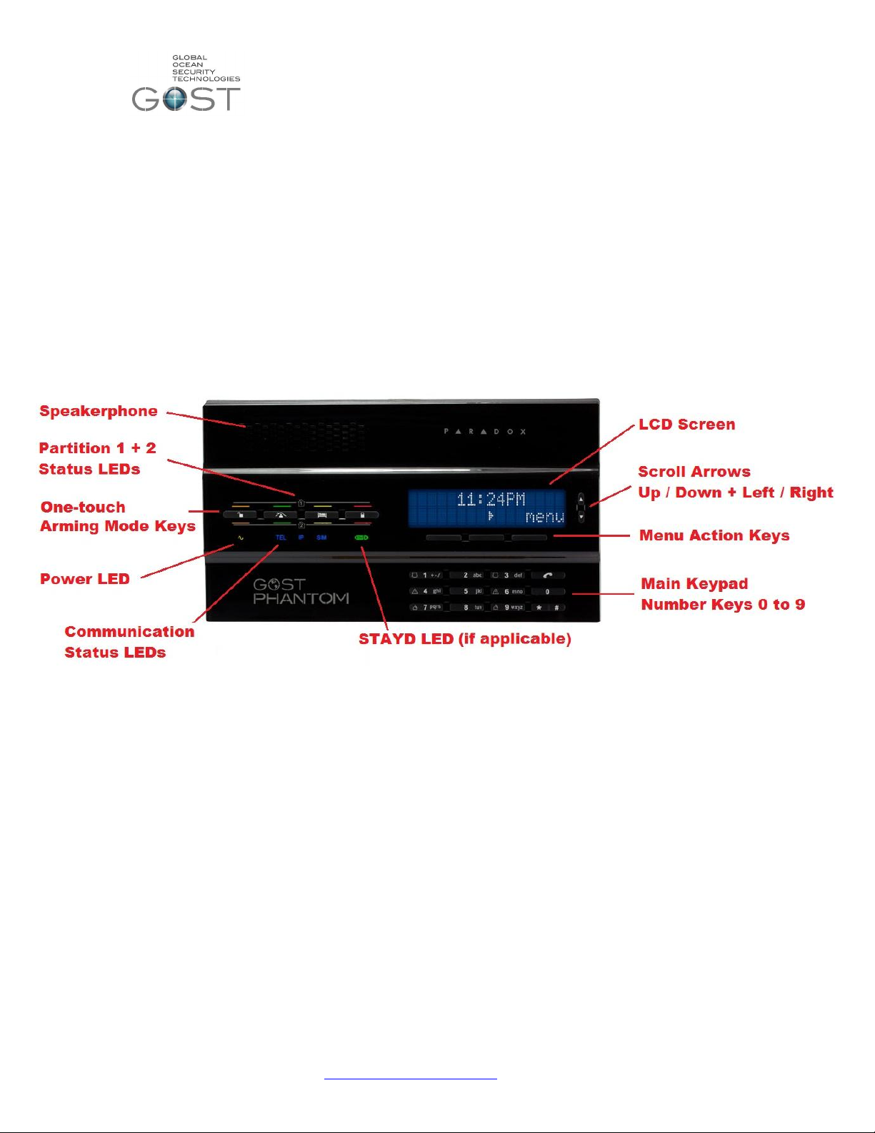
standards of marine electronics. Figure 1 below identifies the keypad functions and LEDs on the front of the panel.
The GOST Phantom allows programming for:
64 Wireless zones from security to utility monitoring throughout vessel
8 wireless relays to control virtually any AC/DC switch, deck lights, sirens, strobes, ice makers, etc.
4 wireless keypads for additional arming control from staterooms, entry points, crew quarters, etc.
4 repeaters to double the wireless range commonly used on metal boats and vessels greater that 125 ft.
4 Siren/Strobes for simple implementation in various points around exterior of vessel
2 doorbell zones for notification at boarding entry points where individuals come aboard the vessel.
2 Independent partitions to arm/ disarm different areas of vessel such as Living Quarters and Crew/Utility Areas.
Figure 1
Location Considerations
The placement of the GOST Phantom aboard the vessel should be well thought out and reviewed with the yacht owner/crew prior to
installation. The installer must make sure that adequate security concerns, end user ease of use, and functionality of speakerphone are taken
into account. Reference the following guidelines before drilling any holes or running any wires.
Interior of boat, away from any direct moisture
Common areas such as the salon, interior helm, or similar primary entry areas of the vessel.
Easy accessibility for someone boarding the boat
On larger vessels greater than 100ft (Approx. 30 meters) try to keep the head unit towards midship to maximize wireless range
Accommodate for wire run accessibility from rear of panel to power source and GSM/Satellite phone*.
*When connecting to third party satellite phone communicator.
Mounting
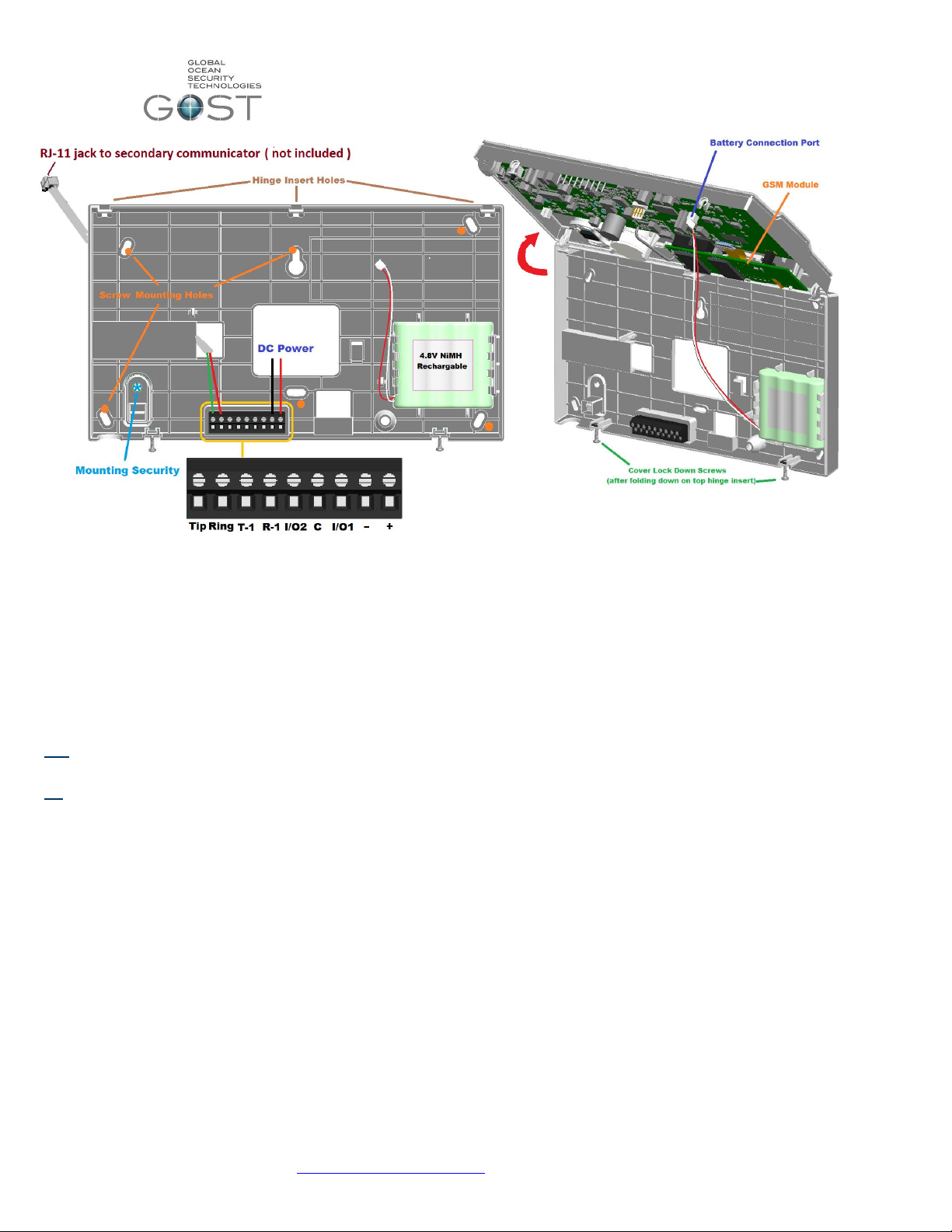
The GOST Phantom head unit conveniently pivots and detaches off its upper hinges for ease of installation. To access the mounting base
plate, unscrew the cover lock down screws from the bottom side as so they are free hanging. Now gingerly fold the bottom apart from the top
hinge (Figure 2 right). Assure that you unplug or plug in the battery cable to the rear of the board when removing or securing the cover
(respectively). Screw in the mounting plate at any of the mounting holes in Figure 2 at the orange dots. The mounting plate also has “Mounting
Security” option that can be used to alarm the GOST Phantom if it is opened or torn off the wall (Figure 2).
support@gostglobal.com or (954) 565-9898 1
Page 2
GOST Phantom – Installation + Programming Guide
Figure 2
Power Supply
The GOST Phantom needs a 7.5 Volt Direct Current (VDC) to operate (Figure 2). The unit includes a 110 - 240 VAC to 7.5
VDC transformer (PA-7). The GOST Phantom will call up to eight recipients in the event of panel AC Power loss (after default
15 minutes) and then restoration. That being said, the average boat being protected by the GOST Phantom will have
consistent AC power via Shore or Generator. If the boat is permanently on an anchor/mooring and powered off the vessels
battery Banks, you will need the12-24 DC to 7.5 DC converter (sold separately).
When deciding whether an AC-DC transformer or DC-DC step down, the installer should ask themselves and/or the
owner/captain this question:
Will the vessel have constant AC power via shore power or generator (aside from brief power switchovers)?
if Yes- Use the supplied PA-7 110-240 VAC-7.5 VDC transformer to power the GOST Phantom.
Make sure the VAC outlet is constantly hot and does not get shut off when the boat is not being used.
If No- Power the GOST Phantom with the step down 7.5VDC converter from the vessels constant domestic 12-24VDC
batteries
Note- Power should be denied when making all electrical connections. Only apply power when all wire connections
have been double checked for proper setup.
Whether using the PA-7 or a DC-7.5VDC step down converter, assure that the proper polarity is established on the two
input lines. Place the Negative wire feed into the position second from the Right and use a small flathead screw driver to
tighten the wire down. Now do the same for the Positive 7.5 VDC wire feed.
Internal Battery Backup
The GOST Phantom uses its own backup battery pack to provide power during a power loss and switchover. A 4.8 VDC
1.8Ah NiMH (Nickel Metal Hydride) rechargeable battery pack is included with the console. Attach the Battery as shown in
Figure 2.
support@gostglobal.com or (954) 565-9898 2
Page 3
GOST Phantom – Installation + Programming Guide
Hardwired Input/Output ports
The GOST Phantom has two hardwired Inputs and/or Outputs which work in conjunction with “I/O 1”, “C”, and
“I/O 2” in Figure 2. An input is defined as a zone and an output is defined as a switch. Hardwired Zones +
Outputs can correspond to either I/O 1 or I/O 2. When programming the I/Os to function in the menu, you will be
prompted as to whether or not you want to use them at “Zone 1” or “Zone 2” and/or “Output 1” or “Output 2”(see
08-System Setup, 01-Zones or 03-Outputs)
If using either Input as a zone, place the Normally Closed sensor between “I/O 1” or “I/O 2” and “C”. Assure
that the terminal block screws are tight with a firm connection. Once the zone is programmed, cycle the magnet
for the zone across the switch once to assure it is functioning properly.
If using either Output as a trigger, you must use a third party relay. The outputs cannot drive more than 50
Milli Amps of current. Assure that the third party relay you use is rated properly for the device you are switching.
The most common relay will be a 12 VDC coil with say a 10 switch. Wire one side of the relay coil to 12VDC and
the other side to “I/O 1” or “I/O 2”. Then place the Negative to the middle “C”. After you program the output and
the event happens, there will be continuity between “I/O 1” or “I/O 2 and “C” for the duration of that event
Communicator
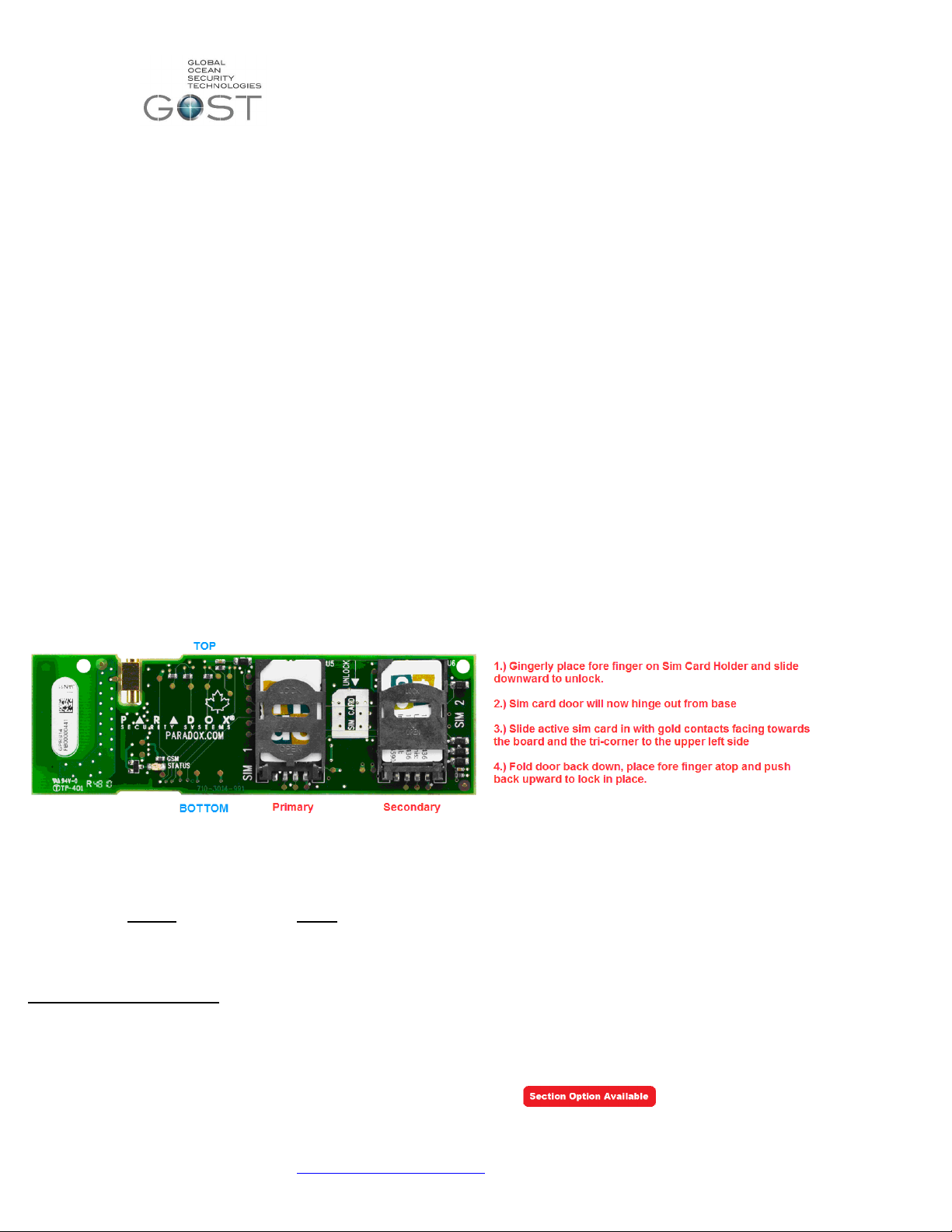
The GOST Phantom has a built in quad band communication module that is capable of both voice call outs and SMS
messaging. There are two sim card holders on this board for redundancy. This comes in handy if the boat is travelling
between countries and needs multiple GSM carriers. The primary sim card simply needs to be inserted into the primary “SIM
1” See description in Figure 3 to insert sim card(s) into onboard module. Most clients will only have the need for one primary
sim card. Have the owner, crew, or provider of the sim card assure they arrange with the GSM carrier to have voice / SMS
messaging available. The GOST Phantom is defaulted to report events thru this communicator as the primary method.
If you are using either a Separate GSM communicator (Insight Package) or Satellite phone, it will be necessary to adjust
the default system setting (08-System Setup-09-Communicator, Page 18) If the Installer is using the GOST Phantom in
conjunction with a GSM communicator or Satellite phone, alarms voice reports only will communicate voice alarms out thru the
“Tip” and “Ring” (no SMS Messaging). In either case, you will most likely have a four conductor RJ-11 telephone cable coming
from the communication method. After the cable is run to the GOST Phantom, take the two center Red and Green wires to the
Ring + Tip (respectively) as displayed in Figure 2 on the previous page.
Figure 3
Programming + Installation Overview
With the GOST Phantom mounted and powered up, it is time to program and install the different wireless entities of the
system. This guide focuses on the primary programming and Installation parts of the install. The system can be programmed
using either the section based method, the menu based approach (easiest and most common method), or a combination of
both. This guide is written in a fluid fashion and it is best to follow the steps in the order that it is written. In some cases, the
GOST Phantom comes with the sensors preprogrammed, in this case see the labels on the respective zones and outputs and
follow installation guidelines only for each wireless entity.
Section Based Programming – This method will need to rarely be used, though it is important for the installer to know that it
exists when some background changes need to be made. It is best to compare Section based programming to “DOS” on a
PC. To enter section based programming: go to the home screen of the panel, hold down the “ 0 “ key for approximately
three seconds, enter the installer code of “1111” (default), and enter the respective section number. Once the respective
values are changed by the installer, it will automatically jump to the next section number or you can simply press “# “to
proceed to the next section. To exit section programming, hit “* * “and “exit”.
NOTE: Section programming option availability will be represented by this icon:
support@gostglobal.com or (954) 565-9898 3
Page 4
GOST Phantom – Installation + Programming Guide
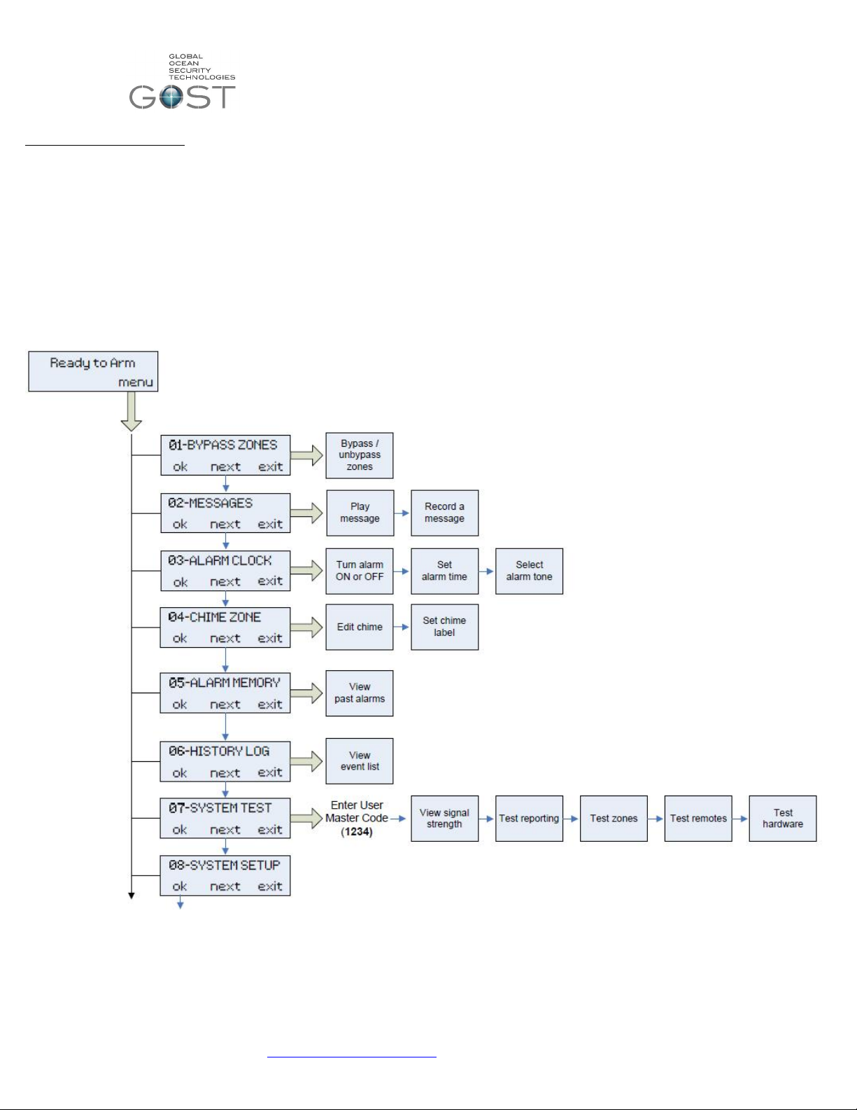
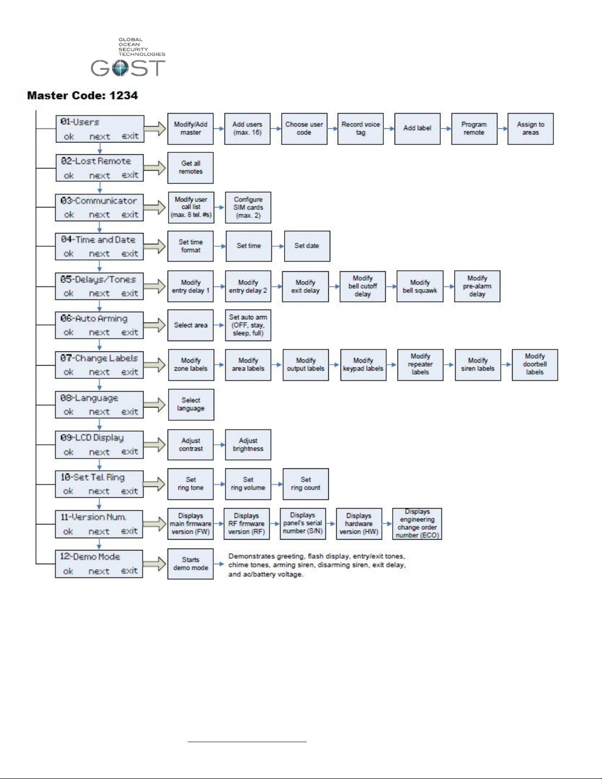
Menu Based Programming – This is the quickest and most productive way to program the GOST Phantoms users, zones,
wireless relays, and many other additional features of the system. This menu is fully navigational via the three menu action
keys underneath the screen (Figure 1). The initial 7 items on this menu are universal and are more geared for the end user
once the installation is done (Figure 4).
The GOST Phantom protects both the client and installer on different levels. When entering the master code at “08-System
Setup” one menu appears, when entering the Installer code a different menu appears (review menu flow charts in Figure 5 and
Figure 6, respectively). An example of this is that the master coder can add/ delete other user codes, while the installer code
cannot. Conversely, the installer code can add/ delete zones, Relays, etc., while the master code can only modify the labels.
Review these flow charts thoroughly before proceeding to programming and installation of the wireless entities of the system.
The installer will need to use both the Installer code as well as the Master code during the installation and programming of the
system. That being said, after installation completion during the handoff/ training to the master user of the GOST Phantom
system it is strongly suggested that the master code be changed.
Figure 4
support@gostglobal.com or (954) 565-9898 4
Page 5
GOST Phantom – Installation + Programming Guide
Figure 5
support@gostglobal.com or (954) 565-9898 5
Page 6

GOST Phantom – Installation + Programming Guide
Figure 6
support@gostglobal.com or (954) 565-9898 6
Page 7
GOST Phantom – Installation + Programming Guide
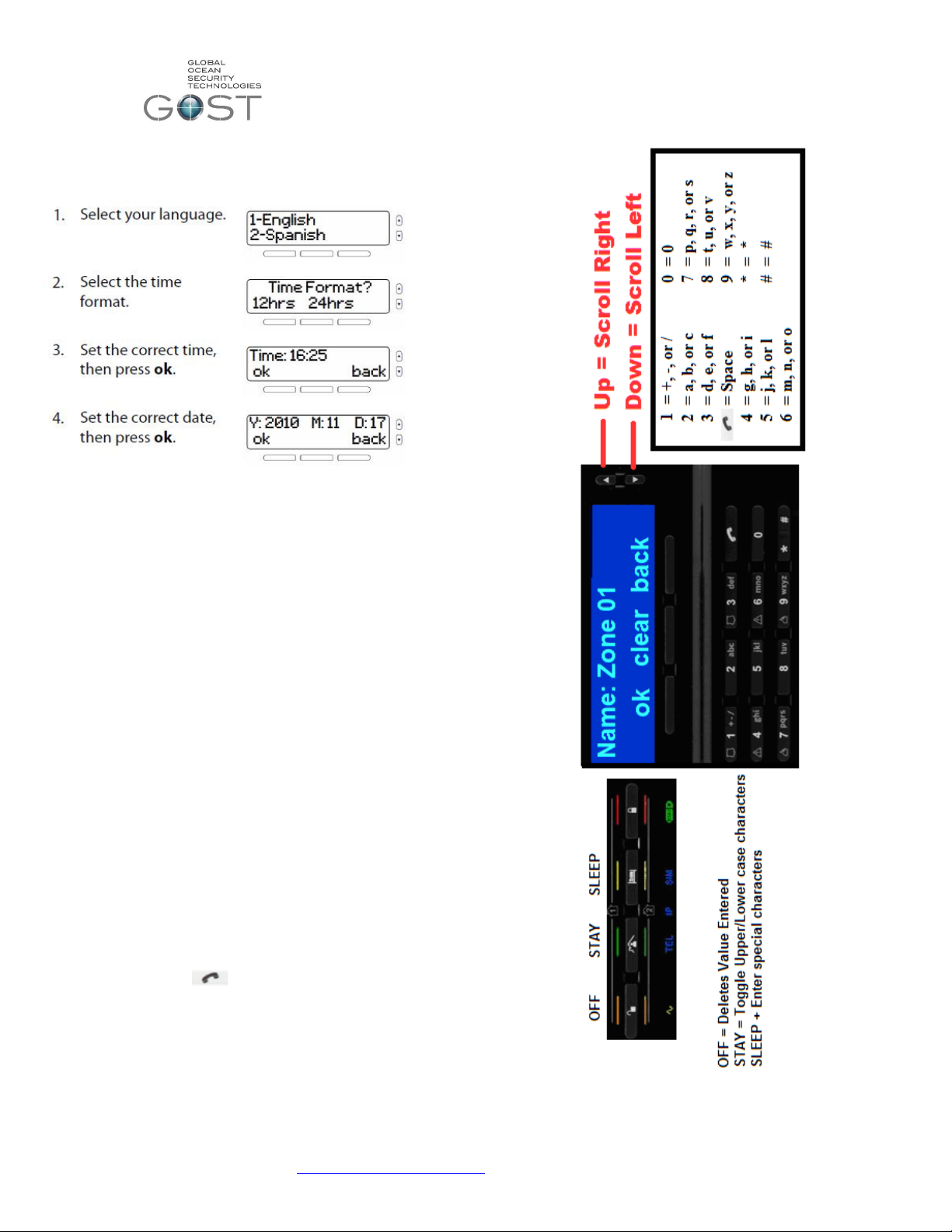
Initial Power up Screen
When you power up the GOST Phantom the
following screen will appear in (Figure 7). Enter
the correct language, time, and date.
Figure 7
Programming Text Message Labels
When using the onboard GSM module for the GOST
Phantom, the use of text messaging to transmit GOST
Phantom conditions is a valuable tool. As you proceed thru the
various menu items for adding users, zones, relays, areas,
etc., you will have the option to enter text labels. See the
example in Figure 8 that describes how to enter labels a zone
the process is the same for entering any text label. You do
not need to do this process now it is important to understand
the functionality of it.
Function 1: Press the center “clear” button to wipe out existing
verbiage (zone 1, user 2, area 1, etc)
Function 2: Enter the digits to the right on Figure 8 for the
respective letter or character. As an example if you press the
The number “2 “once, twice, or three times you will get A, B, or
C respectively.
Function 3: Press the “Up” or “Down” Scroll keys to right to
move cursor right or left respectively
Function 4: Press the “ “ button shifts a blank “Space”
between possible words
Function 5: Press the left “ok” menu action key button to
proceed to next step of programming
support@gostglobal.com or (954) 565-9898 7
Figure 8
Page 8

GOST Phantom – Installation + Programming Guide
08-System Setup
“User Profile”
This is the only initial step of the installation where the
installer will need to enter the master code when entering the
system setup menu. You can program up to sixteen different
users onto the GOST Phantom. A User is defined as a person
with access to the system via a pass code and/or key fob
remote. Common examples of the Master, User 2, and User 3
are the owner, crew member, and boat washer respectively.
Every user can have only one key fob. The User Profile area
of programming allows the master user to change user
passwords, user voice labels, user text labels, and add/delete
key fobs. Once you change the master code (User 1) from the
default “1234”, only the new master code will be able to access
the user profile. The three types of key fobs that are
compatible with the GOST Phantom shown in Figure 9 below.
* Note- For every user code programmed to the GOST
Phantom, there can be a key fob. However for every key
fob programmed, there must be a user code associated to
it.
Figure 9
To program the user codes and Key Fobs follow the steps
below. Note that if adding multiple key fobs you will need to
add additional users. Until the installer is ready to turn over the
system to the system master, it is suggested that you make the
user 2 code “2222”, the user 3 code “3333”, etc. as to keep
things easy to remember. Though it is extremely important to
change the codes later once the owner is ready to take master
user control over their new yacht security and monitoring
system.
08-System Setup
“Installer Programming”
support@gostglobal.com or (954) 565-9898 8
Page 9

GOST Phantom – Installation + Programming Guide
“01 – Zones”
A zone is defined as any assorted wireless sensor that
transmits an open/close condition to the GOST Phantom.
These zones come in the form of door contacts, door contacts
with extension magnets, motion detectors, beam sensors,
smoke detectors, deck sensors, pull sensors, high water
alarms, and low voltage detectors to name the most common.
The GOST Phantom system can hold up to 64 of these zones.
It is important to understand the standard programming steps
to setup each sensor as a zone on the GOST Phantom. Each
sensor may be programmed differently depending on type,
location, and reaction the installer and client wish to obtain
(see Table 1 on next page). It is strongly suggested that the
installer program and install all zones individually as they move
through the installation. It is the quickest and most efficient
way to work thru an installation.
Zone Programming is the first option inside the system
setup Installer menu. When programming the assorted zones
into corresponding zone numbers, it is best to group like zones
within close range of each other. As an example, all door
contacts could be zones 1-4, Motions 5-6, High Waters 7-9,
etc. This allows for more fluidity and ease of use for the end
user. All wireless zones have assorted styles of tamper
buttons on them. This button will be the method by which they
are learned into the system (Figure 10). Assure that the zone
you are working with has its batteries installed or is powered
up, the cover is removed, and the board is exposed when
programming. Reference the individual zone directions
included with each device to correctly install the sensor, power
it up, and find the tamper button. To begin learning the zones,
get to “01-Zones” on the screen.
Figure 10
support@gostglobal.com or (954) 565-9898 9
Page 10

GOST Phantom – Installation + Programming Guide
You are now prompted to select a zone “type”. This is the action
that you want the zone to take when it opens and closes
accordingly. There are many different definitions of zone types.
Thoroughly review the typical zone definitions for the different types
of zones in Table 1. If you still have questions after reviewing the
table, see the standard definitions below it. Press “next” and “ok’ to
navigate and select the desired zone type according to the general
guidelines below for each style zone.
support@gostglobal.com or (954) 565-9898 10
Page 11

GOST Phantom – Installation + Programming Guide
Delay 1/ Delay 2 When armed, Allows default 45
seconds to board boat interior and
disarm at panel
Instant When armed, alarms instantly on the
zone opening
Follow Full Arm When fully armed, follows delay zone
timer, goes off instantly when no entry
delay engaged, and disables when
stay or sleep arming.
Instant/ stay When armed, alarms instantly and
disables when staying.
24 Hr buzzer Buzzer alarm 24/7 on opening
Delay fire 80 second Delay on breach before
alarm (24/7)
“02-Areas”
Assigning Zones to Areas
An “Area” of the GOST Phantom can also be described as a
partition. The GOST Phantom has two partitions. This feature
allows two independent areas of the boat to be armed and
disarmed. An example of this would be when an owner wants
to keep the living quarters aboard his boat independent of the
Engine room, Utility areas, and Crew Quarters of the vessel.
Thus allowing them to disarm the access areas while still
securing their primary cabin. In most instances, the GOST
Phantom will only need one area to arm, however the option is
there to keep two independent areas.
support@gostglobal.com or (954) 565-9898 11
Page 12

GOST Phantom – Installation + Programming Guide
“03-Outputs”
The term output is used to describe any type of relay
control the GOST Phantom is using. The GOST Phantom has
three options to trigger outputs, the onboard hardwired to drive
relay, the GMM-RLYZ1, and the GMM-IP67-RLYZ1.
Any of these three options can be programmed to toggle to its
opposite state when a specific event has occurred onboard.
For example, an Output can be used to activate external
sirens, pulse deck lights, turn on ice makers, and much more.
The GMM-RLYZ1 and GMM-IP67-RLYZ1 communicate
wirelessly to the GOST Phantom. The hardwired Outputs on
the back of the GOST Phantom can trigger an external 12V
relay if wireless connection is not needed. The system can
support up to a total of eight Outputs, all of which must be
programmed to follow certain events. Thoroughly review the
Wireless Output wiring diagram included with the GMMRLYZ1or in Figure 11 below. Before hooking up and
programming the output, it is important to understand the most
common activation event definitions.
Remote Access- This event allows the Output to
activate from a remote control button on the key fob remote.
The user can have the PGM toggle on and off from this button
or even have timing cycle of 1, 5, 15, or 30 seconds/ minutes.
This event is also a secondary option with every Output event.
This comes in handy if you want to be able to have the cockpit
lights “Pulse on Alarm” and still be able to turn the lights on
through the remote as a convenience when
boarding/deboarding the boat. Before programming the Output
to activate on a button, at least one key fob remote must be
programmed to the system (see User Profile).
Follow Bell- This event allows the Output to
activate following the Bell cut-off delay. The bell cut-off delay is
the amount of time that the internal 90 decibel siren of the
GOST Phantom will sound before shutting off. The event
scares away would be thieves while shutting off after a period
of time as to not annoy your fellow dock mates. The unit stays
in alarm and will re-initialize if a zone is breached again. By
default, the bell cutoff delay is four minutes
Alarm activation- This event allows the Output to activate
upon alarm in a variety of ways.
Follow Alarm- The Output will activate for the
entire duration while in alarm. The only way to deactivate
the Output is by disarming the system via key pad, key fob,
or phone.
Pulse on Alarm- The Output will activate on (1sec.) and off
(1 sec.) pulsing for the entire duration while in alarm.
Timed Duration- The Output will activate for an
established period of time and then deactivate once the
time is elapsed. The PGM can be programmed to come on
for 1, 5, 15, or 30 seconds/minutes.
Zone activation- The Output will activate whenever a specific
zone(s) opens. The Output can stay on the entire time the
zone is opened or for a set time frame of 1, 5, 15, or 30
seconds/minutes. The installer can specify all zones or
particular zones to activate the Output. Common examples of
this are interior lights that may come on when a certain door
zone is opened.
Follow arm- The Output will activate whenever the system is
armed. Common examples of triggered devices may be visible
red LEDs on the exterior of the vessel to alert users of armed
status.
Follow stay arm- The Output will activate whenever the
system is stay armed. Common examples of triggered devices
may be interior lamps that come on inside the salon.
Custom setup- The Output can be programmed to
activate/deactivate from a variety of specific events from user 5
disarming to a low battery on zone 7. This feature is for
experienced installers only.
Figure 11
support@gostglobal.com or (954) 565-9898 12
Page 13

GOST Phantom – Installation + Programming Guide
support@gostglobal.com or (954) 565-9898 13
Page 14

GOST Phantom – Installation + Programming Guide
“04-Keypads”
The GOST Phantom is compatible with a
wireless keypad that can be used arm/ disarm the
system from different areas of the boat (Figure 12).
It comes in handy if client wants to keep the GOST
Phantom covert. It also provides additional control
stations for Staterooms, crew quarters, and
secondary entry areas. Power up the keypad in the
designated area according to the criteria in the
included directions. And program according to the
following directions.
Figure 12
support@gostglobal.com or (954) 565-9898 14
Page 15

GOST Phantom – Installation + Programming Guide
“05-Repeaters”
The Repeater (GMM-IP65-RP) is used to double
the wireless range of the GOST Phantom’s assorted
zones, outputs, or wireless keypads. It is used on
vessels usually 80+ Feet where diamond plating,
metallic sound proofing, or multiple bulkheads
reduce wireless range. The GOST Phantom is
compatible with a maximum of four repeaters
support@gostglobal.com or (954) 565-9898 15
Page 16

GOST Phantom – Installation + Programming Guide
“06-Sirens”
The GOST Phantom has the ability to work with
a wireless siren/ strobe (GMM-SRN-STR). This
device is extremely useful where an easily
implemented sound and flashing light could be used
to deter theft. Common locations are under
gunwales aboard the boat or mounted to pilings on
the dock next to the boat. Interior versions are also
available for farther away staterooms where people
need to get waken up on alarm. Note that this
device is its own solution specifically designated for
this area of programming. If using a separate siren
or light triggering application, it should be triggered
with the GMM-RLYZ1 Output control from the
previous section.
support@gostglobal.com or (954) 565-9898 16
Page 17

GOST Phantom – Installation + Programming Guide
“07-Doorbells”
Some clients on larger boats with boarding stairs
like to have a wireless door bell to alert the GOST
Phantom System and their crew that someone is
waiting to board the vessel. It is suggested that a
GMM-IP67-DC with a GNT-Pushbutton be used for
this application as it can be easily moved and
mounted for different docking scenarios.
support@gostglobal.com or (954) 565-9898 17
Page 18

GOST Phantom – Installation + Programming Guide
“08-Delays / Tones”
support@gostglobal.com or (954) 565-9898 18
Page 19

GOST Phantom – Installation + Programming Guide
“09-Communicator”
The GOST Phantom has a built in speakerphone. This feature
can be used with the onboard GSM module or thru the Ring
and tip (RJ-11) for external GSM module or Satellite phone. In
either case the system will call up to eight telephone numbers
in the event of an alarm, however SMS messaging is only
available with the onboard GSM Module.
If using the Ring + Tip connection via RJ-11 to secondary GSM
or Satellite phone dialer. You must now go into Section
Programming and modify Sections (2007) and (2037).
1.) Press “Exit” until you get to the home screen and hold
down the “0” key for three seconds.
2.) Enter the installer Code “1111”
3.) Enter Section ( 2007) and the defaults will display as
(*23*56**)
4.) Press the numbers 1,2,3,5, and 6 and it will now display
(1*******)
5.) Press “#” to confirm the change and move to next section
and continue pressing “#” until you it says Section ( )
again
6.) Enter section ( 2037 ) and the GSM default will display
(02)
7.) Enter “ 01 “ in place to default voice calls thru Ring + Tip
8.) Press “#” or Exit after this change is made and exit out of
sectional programming.
support@gostglobal.com or (954) 565-9898 19
Page 20

GOST Phantom – Installation + Programming Guide
support@gostglobal.com or (954) 565-9898 20
Page 21

GOST Phantom – Installation + Programming Guide
“10-Installer ID”
It is not necessary to modify this area of
programming unless directed by the owner of if the
installer has security concerns of someone changing
installer codes on the system. Consult GOST
support if further information is needed on this
section.
“11-System Test”
This area can be used after the install is complete
to test assorted wireless entities of the system.
support@gostglobal.com or (954) 565-9898 21
Page 22

GOST Phantom – Installation + Programming Guide
Trouble Display
When the GOST Phantom wants you to know
something is wrong, an “i” will appear on the screen
along with an audible beep. After viewing the
trouble by pressing the left menu action key, you
view the trouble, and press “ok” to stop the beeping.
See the Trouble Display area below in Table 2 to
see all of the possible troubles that could appear.
“12-Stay D Path”
This feature is used as a permanent armed
solution that disarms defined areas and subsequent
zone activations accordingly. It will generally
never need to be used. If specific definitions of this
function are needed, please contact GOST.
Table 2
Installer Quick Keys + Resets
This area of the system assists installers in resetting values
to factory defaults, cancelling communication, resetting
outputs, or hearing audible zone Open/Close soundings when
installing alone ( Table 3). In addition the table gives the
Section numbers to factory default the GOST Phantom
completely, the Master User Code Only, or the onboard
GSM/GPRS Module Only.
1. Press and hold 0.
2. Enter your installer code “1111”.
3. Press the required quick-key
support@gostglobal.com or (954) 565-9898 22
Page 23

GOST Phantom – Installation + Programming Guide
Frequently Asked Questions ( F.A.Qs )
FAQ 1: The wireless Extension door contact, High Water
Alarm, and/or Battery low voltage sensor are non responsive
and not registering a condition change (open or close zone)?
Assure that when you programmed the device, you pressed the
tamper button twice within one second, see (See 08-System
Setup, 01-Zones)
FAQ 2: The GSM module connected via ring and tip to the
GSM/Data device is inoperative?
1.) Confirm that the sim card is active with voice time
available for it (and data if using it for an internet
connection with GOST Watch HD)
2.) Confirm that you have gone into sectional programming
to change the communication default from the onboard
module to the secondary GSM module. (See 08-System
Setup, 09-Communicator).
FAQ 3: The Onboard GSM Module will not stop displaying a
trouble for the unused “Sim 2”. This message comes up when
at one point of another a card has been placed in “Sim 2”. The
module needs a reset.
Table 3
Go to section “9002” to factory reset this module only. It will
then reboot the module and accommodate for only the sim
card inserted and leave the rest stagnant.
FAQ 4: The GOST Phantom is powered off of the AC to DC
transformer that is included with the system. The Voice
reporting is configured to report trouble for AC power
Loss/Restoration, thus when the Boat looses shore power a
call will be placed. I am not getting the call.
The Panel must be denied power for 15 minutes by default,
only then will the call be placed. If you want to change it to a
lower threshold, see section below
Go to section “2027” and type in the variable you want from
01 to 255 minutes. Then continue to press “#” until you see
“Exit” and press the right menu action key.
support@gostglobal.com or (954) 565-9898 23
 Loading...