

Gost GMM-RLY-Z1 Installation Manual
Installation Manual
Introduction
This GOST Apparition System is the next generation security, monitoring, and access control system that
provides the yacht with protection using powerful features that are easy to use. The elegant and user-friendly
keypads will allow you easy access to the security system's functions and information at the touch of a button.
GOST Apparition Features
Provides constant supervision and two-way communication between the control panel and all its
modules
Supports up to 254 expansion bus modules
Connect modules up to 914m (3000ft) from the panel
Sabotage-proof technology without additional wiring
Expandable to 192 zones
Built-in access control features
Automatic Daylight Saving Time feature
999 user codes
8 partitions
2048 events buffered
Program remote controls using the master or installer codes
Up to 999 remote controls with one RTX3
2.5A switching power supply
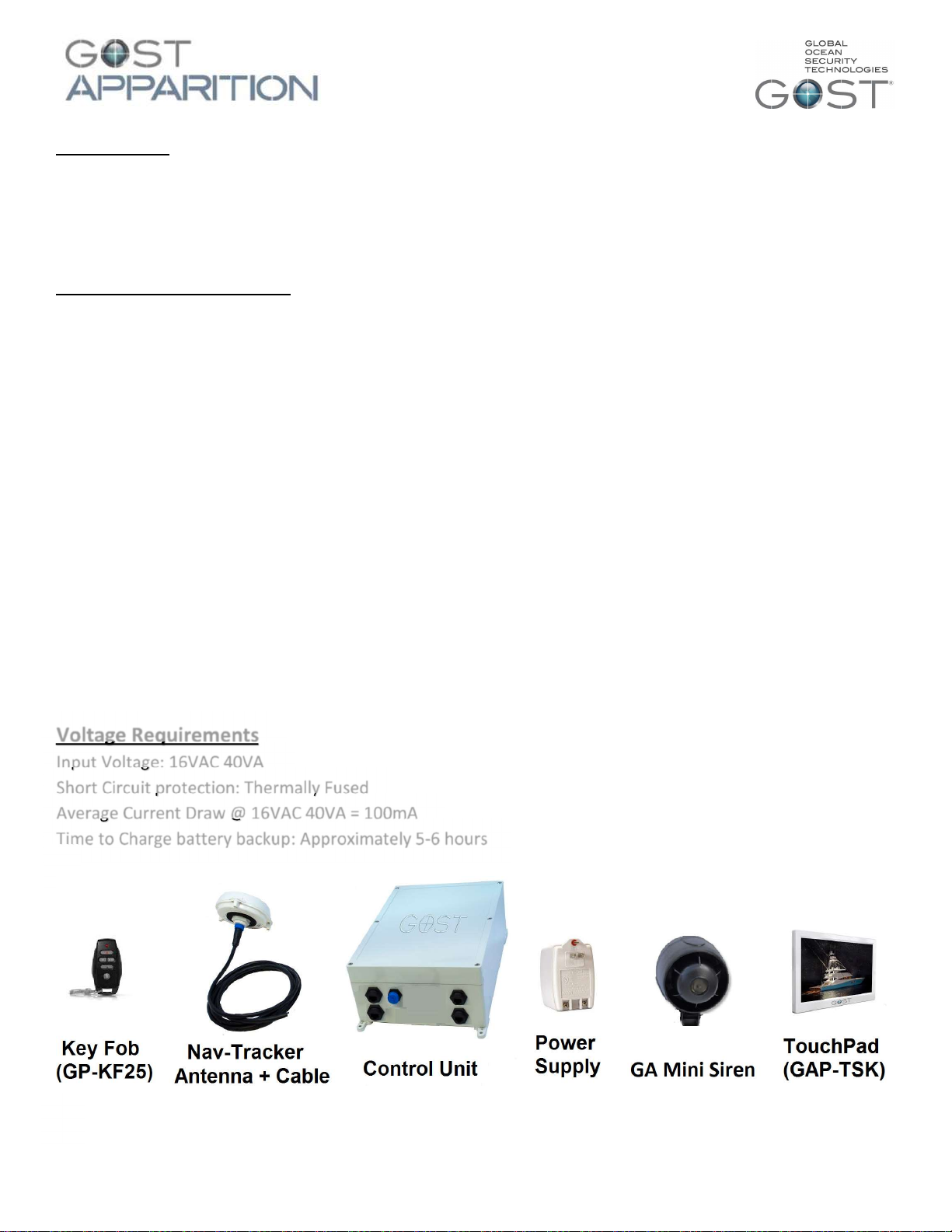
Voltage Requirements
Input Voltage: 16VAC 40VA
Short Circuit protection: Thermally Fused
Average Current Draw @ 16VAC 40VA = 100mA
Time to Charge battery backup: Approximately 5-6 hours
1
Control Unit + corresponding Siren Locations
The Control Unit provides the logic for all the wireless zones, outputs, and key fobs while supplying a full
battery backup to the tracking antenna in the event that input voltage is lost. Also, there is a 12 VDC Siren
output from the box that hooks up to the Positive and Negative of the siren. Consider the following when
deciding on a location:
Keep Control Unit accessible but not visible. The Enclosure is IP67 rated, though it is best not to mount
it in an exposed area where it is more susceptible to water spray or tampering
Common Places on a vessel include vessel’s Electronic areas with constant AC power.
Keep it hidden as best as possible as if thieves cut the power supply, the battery backup in the control
unit is the last line of tracking power supply for the antenna.
The cover may have to be removed for yearly maintenance, make sure that it is accessible.
Mini Siren – Mount in a area where it can be heard. If inside, perhaps in a AC air duct where it is
covert. If exterior, below a gunwale or in engine room near air baffles (so sound projects outside).
Mini Siren –This wire can be extended up to 50ft if you need to reach external areas.
TouchPad Locations
The system comes with one TouchPad display and can have additional displays placed in parallel to the four
wire Commbus line. Assure the criteria is met below for installations and review with owner, captain, or yacht
manager prior to install
Entry areas in salon, port or starboard entries, crew quarters, Master Staterooms, etc
Dry interior location (do not install outside the boat).
Has a wire run for the 4 conductor Commbus wire to the Control Unit
Nav-Tracker Antenna Location Considerations (if used)
Think Security. The location of the antenna is critical to proper system operation and should be
toughly scrutinized.
The antenna is able to penetrate up to 1/2 inch of solid fiberglass, making way for covert installs.
Locate the antenna a minimum of two feet away from metallic obstructions such as hand rails, rod
holders and cleats.
Choose a location that is not directly under or near radar arrays to prevent possible interferences.
Make sure that the underside of the antenna is accessible to connect the antenna cable. Leave
approximately four inches directly underneath the antenna to provide space for the connection.
Mount on a flat horizontal surface.
The antenna communicates its data to the Inmarsat Geostationary based satellite network. As a rule, a
clear line of site towards the equator is needed.
Whenever possible, dry run the installation procedure and test the location beforehand.
2
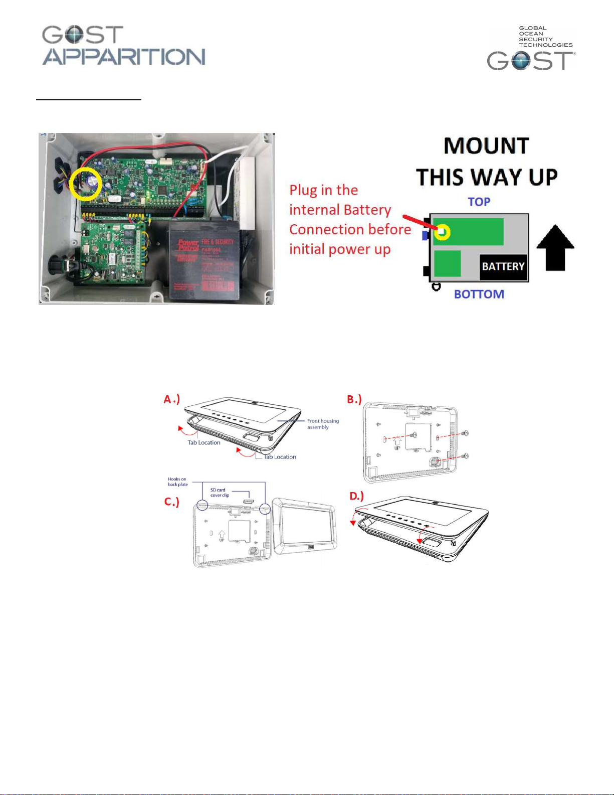
Installations steps
1.) Before hooking up 4 conductor CommBus wires or power, you need to open the cover up and plug in
the battery backup to their respective terminal as shown below.
2.) Mount the control unit using the rear mounting brackets in the pre-established location and mound
according to the picture above with the internal batteries sitting upright.
3.) Mount the Touchpad according to the pre-established location(s). The panel pops open according to
the diagram below. Assure that the plug to the back of the TouchPad for the CommBus cable is
hooked up and the wires access the rear to butt connect to the CommBus cable.
4.) Connect the 4 Wire CommBus from the rear of the TouchPad via Butt Connector to the CommBus
Cable. Run the wire back to the control unit and connect to the system. If there is more than one
keypad (or multiple BUS modules). Wire them in parallel (daisy chain) to the BUS connection at the
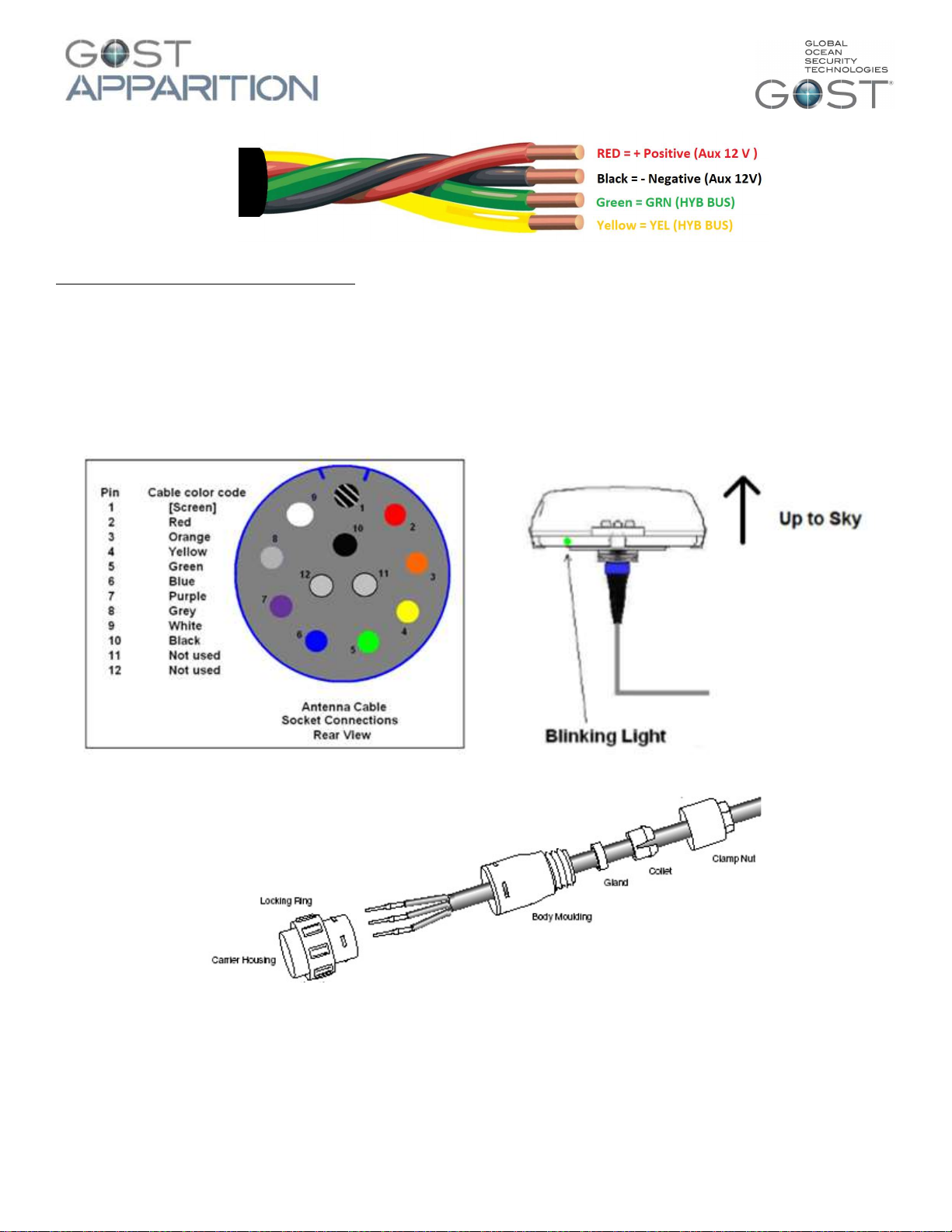
panel. The 4 Conductor CommBus wire consists of positive 12VDC, negative, Rx, and Tx wires as shown
below. ***The Commbus cable included may have a “WHITE” wire instead of a “Yellow”. These two
wires should be connected together (as sure Red, black, and green are connected to their like
corresponding color).
3
Nav-Tracker Antenna Installation (if used)
1.) Thoroughly read the Nav-Tracker antenna location considerations and mount the antenna according to
this criterion. To assist the installer with the antenna wire run, the antenna cable has one end with a
connection and the other with ten sockets protected by heat shrink. Snake the cable from antenna to
the control unit, remove the heat shrink, and connect the pin arrangement at the control unit
according to the figures below.
2.) There is a light at the base of the antenna (illustration above right). Assure that the antenna is rotated
to a position where the light is visible to the installer. When the unit is first powered up it will initially
blink red, then gradually change to orange, and then green. The antenna should be blinking green
within about five minutes of startup. If it does not, confirm that the signal is not getting blocked and
that the installation adheres to the location considerations.
4
3.) Leave the antenna plugged in. Direct the owner to the sticker at the bottom of the included user guide to
activate the antenna. Antennas that remain inactivated for more than two weeks are automatically sent a
disable command. A re enabled command can be sent, though immediate activation is suggested after
installation. *Pre-Activation of the antenna is preferred whenever possible to simplify install.
Cellular communicator options and connections
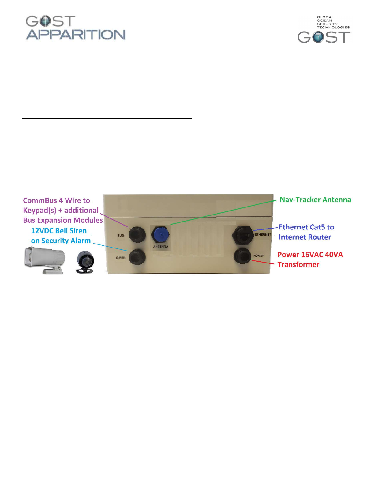
4.) If there is an on-board communicator (cellular or V-sat) proceed to connect the Ethernet cable from
the network on-board the vessel to the Ethernet connector on the outside of the enclosure (picture
below). This will allow email alerts to be sent without the need for additional SIM cards. If no
communicator is present on the vessel an active SIM can be installed in the cell communicator inside the system
enclosure. This will allow texting (with zone descriptions) of any event on the system as well as allow remote
arming/disarming via text message.
After all the BUS modules and backup batteries are connected, the system can now be connected to
power. Connect the power cable to the 16Vac 40VA transformer provided and connect it to a source that will
have power at all times (inverter circuits or generator circuits depending on common vessel use). After
powering up the system allow 2 to 3 minutes for system scan.
After the system scan is complete the keypad will show its Main Screen. From here you can update the
panel time and date simply by pressing the time and date on the screen and entering the master code for
access. Once you have updated the time and date you are ready to test your system. You will perform your
tests from the system’s keypad. Below you can find some guides through the keypads menu and functions.
*if new zones or outputs need to be added to programming it must be done before your system test to ensure correct functionality of
all zones. If any zones or outputs are added in the future, a complete system walk test must be performed.
5.) Siren Bell output - The GOST Apparition has a hardwired siren output the fires off 12 Volts DC for a default
period of 4 minutes upon any security alarm zone. Connect the two wires from the siren directly to the
respective red and black wires coming out of the Siren plug on the control unit. DO NOT MOUNT THE SIREN
DIRECTLY NEXT TO THE GOST APPARITION CONTROL UNIT. Connect the two conductor siren wire to the plug
and run it to a separate compartment, preferably where it is not muffled and can draw attention to the boat.
Preferably this is up on a Fly Bridge, under a gunwale, or inside a engine room (to name a few). The siren should
not be mounted where it is under constant direct spray.
5
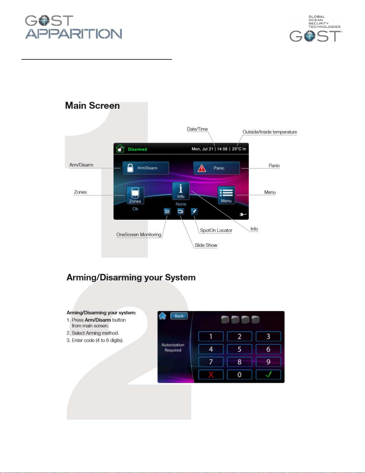
Basic Operation of the TouchPad (GAP-TSK)
The touchpad is a versatile input device that lets Installers + Master users manage your system. Management
and configuration of the system through the touchpad can be restricted to users of your choice.
Default Master Code: 1234
Default Installer Code: 111111
6
 Loading...