

Page 1
U181A
80 A Einphasiger Energiezähler - 80
D
- BEDIENUNGSANLEITUNG
GB
- USER MANUAL
Änderungen vorbehalten.
Subject to change without prior notice.
ACHTUNG!
Die Installation und Inbetriebnahme des Zählers darf nur von ausgebildeten Fachkräften durchgeführt werden. Vor jeder Tätigkeit am Gerät muss
die Versorgung getrennt werden.
WARNING!
Device installation and use must be carried out only by qualified sta.
Switch o the voltage before device installation.
A single phase energy counter
3-349-661-15
1/10.11
VERFÜGBARE AUSFÜHRUNGEN
AVAILABLE MODELS
Modell
Model
U181A 230...240 V 50/60 Hz
Spannungsbereich
Voltage
Frequenzbereich
Frequency
MID
n
ANSCHLUSSBILDER
WIRING DIAGRAMS
EINPHASIG - 2 LEITER
1 PHASE - 2 WIRES
S0-2
S0-1
Tari
2
3
4 5
1
<
L
<
I-U NI
L
N
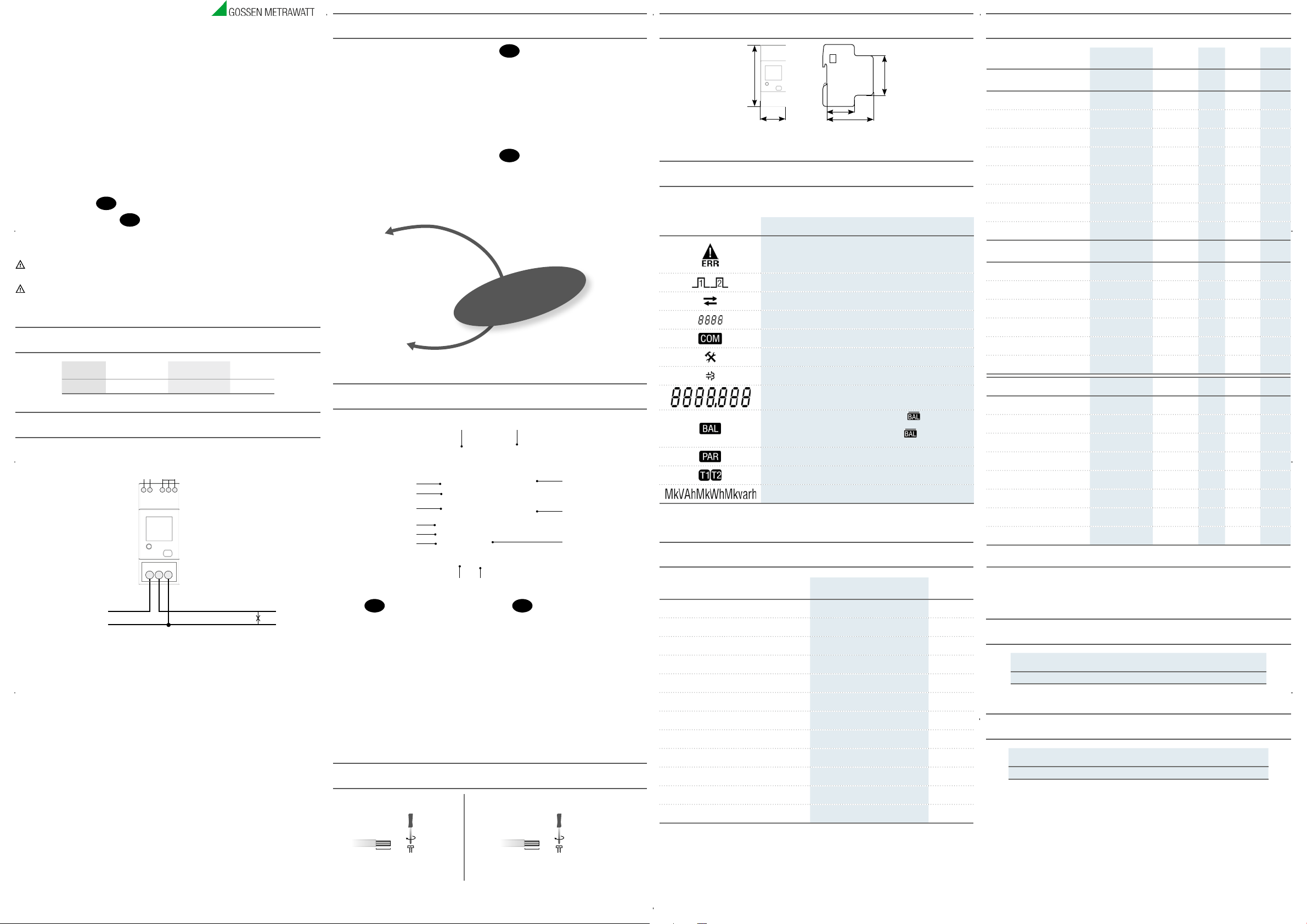
ÜBERSICHT
OVERVIEW
LOMBIERBARE
P
EALABLE
S
SYMBOLE AUF FRONTSEITE (BEISPIELE)
SYMBOLS ON FRONT PANEL (EXAMPLE)
A B
M
L
K
J
I
H
G F
D
DEUTSCH
A. Firmenlogo
B. Gerätenamen (z.B. U181A)
C. Homologationsnummer
D. MID Eichung Symbol
E. Seriennummer
F. Data Matrix
G. Integrationskonstante (Messtechnische LED)
H. Schutzart
I. Anschlußbild (Einphasig, 2 Leiter)
J. Nennspannung/Frequenz
K. Grundstromwert (Max Strom)
L. Genauigkeitsklasse
M. Arbeitstemperaturbereich
KABELABISOLIERTE LÄNGE
CABLE STRIPPING LENGTH
Verdrahtung an den Messeingängen (I & U)
Connection measuring terminals (I & U)
Verdrahtung an S0 / Tarif Klemmen
S0 output / tari terminals connection
D
DEUTSCH
1. Klemme für Tarifeingang
2. S0 Ausgangsklemme
3. LCD mit Hintergrundbeleuchtung
4. Prüf-LED
5. Multifunktiontaste
6. Strom-, Spannung- und Neutralklemmen
7. Sicherheitsaufkleber
(DARF NICHT ENTFERNT WERDEN)
8. Infrarot-Schnittstelle
GB
ENGLISH
1.
Tari input terminals
2.
Terminals for the two S0 outputs
3.
Backlight LCD
4.
Test-LED
5.
Multifunction key
6.
Current,voltage and neutral terminals
7.
Safety-sealing (DO NOT REMOVE)
8.
Optical COM port
!
COVERS
!
LEMMENABDECKUNG
K
TERMINAL
C
D
E
GB
ENGLISH
A.
Company logo
B.
Device name (e.g. U181A)
C.
Type approval certification
D.
MID approval symbols
E.
Serial number
F.
Data Matrix
G.
Meter constant (metrological LED)
H.
Protection class
I.
Wiring type (1phase, 2 wires)
J.
Nominal voltage/frequency
K.
Base current (max current)
L.
Accuracy class
M.
Working temperature
ABMESSUNGEN (mm)
SIZE (mm)
90
36
BEDEUTUNG DER SYMBOLE AUF DER LCD
MEANING OF SYMBOLS ON THE LCD
Die Displaydiagnose erfolgt durch Drücken der Multifunktionstaste für 10 s.
Display test can be carried out by pressing the key for 10 s.
SYMBOL
SYMBOL
BESCHREIBUNG
DESCRIPTION
Beschädigte metrologische Parameter (auf dem Hauptanzeigefeld wird Code: XX angezeigt).
Der Zähler ist ungeeignet und sollte sofort an der Hersteller gesandt werden.
Metrological parameters corrupted (Code: XX will be displayed in the main area).
The counter cannot be used and it must be returned to the Manufacturer.
Nummer des aktiven S0 Ausgangs
Active S0 output number
Bezogener (>), gelieferter (<) Leistungs- oder Energiewert
Imported (>), exported (<) power or energy value
Identifiziert die Einstell- (SETUP) oder Info (INFO) Seiten
Identify the Setup page (SETUP) or the Info page (INFO)
Schnittstelle aktiv
Communication ON status
Einstellseiten: ”Parameterabfrage oder -einstellung” ist aktiv
SETUP pages: ”Querying or changing parameters” is active
Kapazitiv- /Induktivwert
Capacitive / inductive value
Hauptanzeigefeld
Main area
Symmetrischer Zählerwert. Wenn eine Linie über das Symbol ( )
angezeigt wird, ist der Wert NEGATIV.
Balance counter value. If a line is displayed over the symbol ( ),
the displayed value is NEGATIVE.
Teilzählerwerte. Blinkt das Symbol, so ist der Zähler gestoppt.
Partial counter value. If flashing, the counter is stopped.
Zählerwert des Tarifs 1 oder 2
1 or 2 tari counter value
Messeinheitsfeld
Measuring unit area
TASTENFUNKTION
KEY FUNCTIONS
FUNKTION
HOW TO
Gruppe blättern
Scroll loops
In den Seiten einer Gruppe blättern
Scroll pages in a loop
Zugang zu den Einstellseiten
Access Setup pages
Die Einstellung eines Wertes/Anzahl starten
Enable setup for a value/digit
Einen Wert / Anzahl ändern
Change a value/digit
Bestätigung eines Wertes / Anzahl
Confirm a value/digit
Eine Anzahl ändern (Y, N, C)
Change item (Y, N, C)
Bestätigung einer angezeigten Anzahl (Y, N, C)
Confirm the displayed item (Y, N, C)
Anzeige der dem Zähler zugeordneten Funktionen
Display the functions available for the shown counter
Eine Funktion ändern (Start, Stop, Res)
Change function (Start, Stop, Res)
Bestätigung der angezeigten Funktion (Start, Stop, Res)
Confirm the displayed function (Start, Stop, Res)
Displaydiagnose
Display test
WO
WHERE
Jede Seite außer der Einstellung
Any page except for Setup
Jede Seite einer Gruppe
Any loops page
“Setup?” Seite
“Setup?” page
Einstellseiten
Setup pages
Einstellseiten
Setup pages
Einstellseiten
Setup pages
“Save?” Seite
“Save?” page
“Save?” Seite
“Save?” page
Teilzählerseiten
Partial counters pages
Teilzählerseiten
Partial counters pages
Teilzählerseiten
Partial counters pages
Jeder Seite außer der Einstellung
Any page except for Setup
MESSUNGEN
MEASUREMENTS
SYMBOL
SYMBOL
45
44
65
WIE LANGE
PRESS TIME
Zweimal kurz
Twice quickly
Sofort
Instantaneous
›3 s
Zweimal kurz
Twice quickly
Sofort
Instantaneous
Zweimal kurz
Twice quickly
Sofort
Instantaneous
›3 s
›3 s
Sofort
Instantaneous
›3 s
›10 s
ECHTZEITWERTE
INSTANTANEOUS VALUES
Spannung
Voltage
Strom
Current
Leistungsfaktor
Power factor
Scheinleistung
Apparent power
Wirkleistung
Active power
Blindleistung
Reactive power
Frequenz
Frequency
Leistungrichtung
Power direction
GESPEICHERTEN ANGABEN
RECORDED DATA
Gesamtwirkenergie
Total active energy
Gesamtblindenergie ind. und kap.
Total ind. and cap. reactive energy
Gesamtscheinenergie ind. und kap.
Total ind. and cap. apparent energy
Energiezähler Tarif T1/T2
T1/T2 tari energy counters
Rücksetzbare Energieteilzähler
Resettable partial energy counters
Energiebilanz
Energy balance
WEITERE ANGABEN
OTHER INFORMATION
Aktueller Tarif
Present tari
Spannung über / unter der Grenze
Undervoltage/overvoltage
Strom über / unter der Grenze
Undercurrent/overcurrent
Frequenz über / unter der Grenze
Underfrequency/overfrequency
Teilzähler
Partial counters
Laufende Kommunikation
Active communication
Laufende S0 Impulse
Active S0 pulse
Fehlerstand
Error condition
BEDEUTUNG = STANDARD = BIDIREKTIONALWERT
LEGEND = STANDARD = BIDIRECTIONAL VALUE
In der S0 Spalte sind alle Zählerstände gelistet, die bei den “S0 AUSGÄNGEN” wählbar sind. Es ist nicht möglich, denselben Zähler für beide Ausgänge
auszuwählen.
All the counters programmable for S0 outputs are shown in “SO OUTPUT” column. It is not allowed to set the same counter for both outputs.
V V
I A
PF
S kVA
P kW
Q kvar
f Hz
IMP/EXP
L kWh
L kvarh
L kVAh
L kWh, kvarh, kVAh
L kWh, kvarh, kVAh
L kWh, kvarh, kVAh
SYMBOL
SYMBOL
T 1/2
VOL, VUL ON/OFF
IOL, IUL ON/OFF
fOL, fUL ON/OFF
PAR START/STOP
COM ON/OFF
S0-1, S0-2 ON/OFF
ERR 01/02
IMPULSE AUF S0-AUSGANG
PULSES ON S0 OUTPUT
S0 IMPULSE
S0 PULSES
500 imp/kWh & imp/kvarh & imp/kVAh
PRUEF-LED
METROLOGICAL LED
IMPULSE DER PRUEF-LED
METROLOGICAL LED PULSES
1000 imp/kWh
MESSEINHEIT
MEASURE UNIT
WERT/STAND
VALUE/STATUS
ANZEIGE
COM PORT
DISPLAY
COM PORT
ANZEIGE
COM PORT
DISPLAY
COM PORT
S0 AUSGANG
S0 OUTPUT
15 mm
Ein PZ2 Schraubdreher anwenden
Use a PZ2 screwdriver
2 Nm
0,5 Nm
5 mm
Ein 0,8x3,5 mm Flachschraubendreher anwenden
Use a blade screwdriver with 0.8x3.5 mm size
Page 2
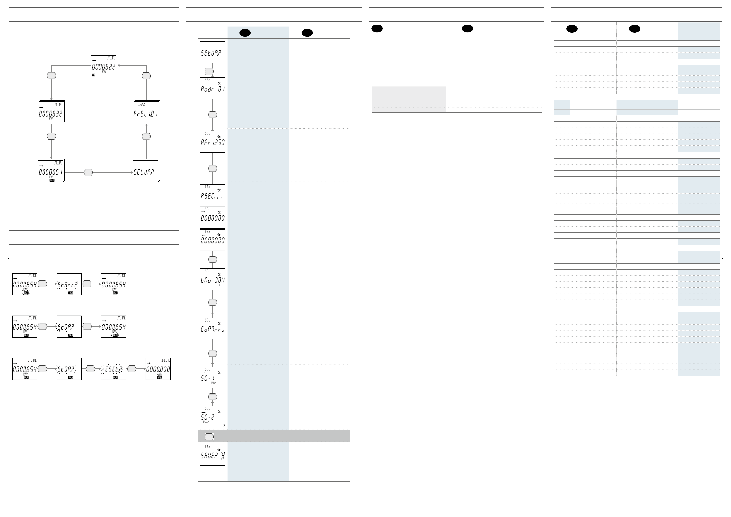
ANZEIGE REIHENFOLGE
PAGE STRUCTURE
Die Seiten des Gerätes sind in 5 Gruppen verteilt.
Device pages are grouped in 5 loops.
GRUPPE 1: WERTE DER TARIFZÄHLER 1-2
LOOP 1: TARIFF 1-2 COUNTERS
Zweimal schnell
Twice quickly
GRUPPE 2: GESAMTZÄHLER WERTE
LOOP 2: TOTAL COUNTERS
Zweimal schnell
Twice quickly
GRUPPE 3: TEIL- BILANZZÄHLERWERTE UND ECHTEZEITWERTE
LOOP 3: PARTIAL-BALANCE COUNTERS AND REALTIME VALUES
Die Taste einmal drücken, um die Seiten einer Gruppe zu blättern.
Press the key once to scroll pages in a loop.
Zweimal schnell
Twice quickly
GRUPPE 5: GERÄTEANGABEN
GRUPPE 4: EINSTELLUNGEN
DIE TEILZÄHLER STARTEN / SPERREN / ZURÜCKSETZEN
HOW TO START / STOP / RESET PARTIAL COUNTERS
Diese Funktion ist nur bei der Teilzählerseite verfügbar.
Feature available only on partial counter pages.
ANGEZEIGTE TEILZÄHLER STARTEN
HOW TO START DISPLAYED PARTIAL COUNTER
› 3 s › 3 s
STOPPEN ZUVOR GESTARTETER TEILZÄHLER
HOW TO STOP DISPLAYED PARTIAL COUNTER PREVIOUSLY STARTED
› 3 s › 3 s
ANGEZEIGTE TEILZÄHLER ZURÜCKSETZEN
HOW TO RESET DISPLAYED PARTIAL COUNTER
› 3 s › 3 s
Zweimal schnell
Twice quickly
LOOP 5: DEVICE INFO
Zweimal schnell
Twice quickly
LOOP 4: SETUP
EINSTELLSEITEN
SETUP PAGES
› 3 s
D
DEUTSCH
ZUGANGSSEITE ZUR EINSTELLUNG
MODBUS ADRESSE (01÷F7 Hex)
Verfügbar nur mit dem entsprechenden
RS485 – Kommunikationsmodul
1. Drücken Sie die Taste zweimal kurz,
die erste Stelle blinkt.
2. Zur Wertänderung drücken Sie
die Taste einmal.
3. Zur Bestätigung drücken Sie die Taste
zweimal kurz.
4. Die Punkte 2 und 3 zur Einstellung der
darauolgenden Stelle wiederholen.
MBUS PRIMÄRADRESSE (0÷250)
Verfügbar nur mit dem entsprechenden
MBUS – Kommunikationsmodul
1. Drücken Sie die Taste zweimal kurz,
die erste Stelle blinkt.
2. Zur Wertänderung drücken Sie
die Taste einmal.
3. Zur Bestätigung drücken Sie die Taste
zweimal kurz.
4. Die Punkte 2 und 3 zur Einstellung der
darauolgenden Stelle wiederholen.
MBUS SEKUNDÄRADRESSE
(0÷99999999)
Verfügbar nur mit dem entsprechenden
MBUS – Kommunikationsmodul
Der Wert wird auf zwei Seiten angezeigt:
•Seite 1 (> ): von Stelle 7 zu 1
•Seite 2 (< ): von Stelle 8 zu 2
1. Zweimal kurz die Taste drücken, damit die
Stelle 8 der Sekundäradresse blinkt.
2. Zur Wertänderung drücken Sie
die Taste einmal.
3. Zur Bestätigung drücken Sie die Taste
zweimal kurz.
4. Die Punkte 2 und 3 zur Einstellung der
darauolgenden Stelle wiederholen.
KOMMUNIKATIONSGESCHWINDIGKEIT
Die Seite und entsprechend Wertebereiche hängen von dem angeschlossenen Kommunikationsmodul ab
1. Drücken Sie die Taste zweimal kurz,
die erste Stelle blinkt.
2. Zur Wertänderung drücken Sie
die Taste einmal.
3. Zur Bestätigung drücken Sie die Taste
zweimal kurz.
MODBUS MODUS
(RTU=8N1, ASCII=7E2)
Verfügbar nur mit dem entsprechenden
RS485 Kommunikationsmodul
1. Drücken Sie die Taste zweimal kurz,
die erste Stelle blinkt.
2. Zur Modusänderung drücken Sie
die Taste einmal.
3. Zur Bestätigung drücken Sie die Taste
zweimal kurz.
S0 ZUGEWIESENER ZÄHLER (1-2)
1. Zur Zähleridenfizierung (z. B. >, kWh)
drücken Sie die Taste zweimal kurz.
2. Zur Änderung der zugewiesene Zähler
drücken Sie die Taste einmal.
3. Zur Bestätigung drücken Sie die Taste
zweimal kurz.
GB
ENGLISH
SETUP ACCESS
PAGE
MODBUS ADDRESS (01÷F7 Hex)
Available only in case of combined
RS485 – module
1.
Press the key twice quickly, the first digit will
start to flash.
2.
Press the key once to change the value.
3.
Confirm by pressing the key twice quickly.
4.
Repeat points 2 and 3 for the next digit.
MBUS PRIMARY ADDRESS (0÷250)
Available only in case of combined
MBUS – module
1.
Press the key twice quickly, the first digit will
start to flash.
2.
Press the key once to change the value.
3.
Confirm by pressing the key twice quickly.
4.
Repeat points 2 and 3 for the other digits.
MBUS SECONDARY ADDRESS
(0÷99999999)
Available only in case of combined
–
module
MBUS
The value is displayed on 2 pages:
•
page 1 (>): digit from 7 to 1
•
page 2 (<) : digit from 8 to 2
1.
Press the key twice quickly, the digit 8 of the
secondary address will start to flash.
2.
Press the key once to change the value.
3.
Confirm by pressing the key twice quickly.
4.
Repeat points 2 and 3 for the other digits.
COMMUNICATION SPEED
Page and range available according to
the combined communication module
1.
Press the key twice quickly, the value will
start to flash.
2.
Press the key once to change the value.
3.
Confirm by pressing the key twice quickly.
MODBUS MODE
(RTU=8N1, ASCII=7E2)
Available only in case of combined
RS485 module
1.
Press the key twice quickly, the mode will
start to flash.
2.
Press the key once to change the mode.
3.
Confirm by pressing the key twice quickly.
COUNTER ASSIGNED TO S0 OUTPUT (1-2)
1.
Press the key twice quickly, the items which
identify the counter (e.g. >, kWh) will
start to flash.
2.
Press the key once to change the counter to be
assigned to the output.
3.
Confirm by pressing the key twice quickly.
INFO SEITEN
INFO PAGES
D
DEUTSCH
Bis zu 3 INFO Seiten können vorhanden sein. Die folgenden
Angaben werden angezeigt:
1. Firmwarestand
2. Checksum
3. Vorhandenes Kommunikationsmodul im Betrieb
Die dritte Seite, die das im Betrieb Kommunikationsmodul anzeigt,
hängt von dem vorhandenen Modul ab (die Tabelle wird verwiesen).
Diese Seite fehlt wenn kein Modul vorhanden ist.
VORHANDENES KOMMUNIKATIONSMODUL
COMBINED COMMUNICATION MODULE
MBUS Mbus
RS485 MODBUS Modbus
LAN GATEWAY Lan
GB
ENGLISH
Up to 3 INFO pages can be displayed to show details about:
1.
counter firmware version
2.
checksum
3.
combined communication module in use
The third page, which shows communication module in use,
can change according to the module combined with the counter
(see table). If the counter has no combined module this page
will not be displayed.
ANGABEN AUF DER INFO SEITE
DETAIL DISPLAYED ON THE INFO PAGE
TECHNISCHE EIGENSCHAFTEN
TECHNICAL FEATURES
D
DEUTSCH
Angaben gemäß der Richtlinien
ALLGEMEIN
Gehäuse gemäß Richtlinie
Klemmen gemäß Richtlinie
HILFSSPANNUNG
Hilfspannung wird vom Messkreis
aufgenommen
Nennspannungsmesswert
Verbrauch (je Phase)
Nennfrequenz
SPANNUNG/FREQUENZ UND ANSCHLUSSBILDER -
MODELL
MODEL
U181A Einphasig 2 Leiter -
STROM
Max Wert I
(Ib)
Wert I
ref
Wert I
tr
Wert I
min
Startstrom I
GENAUIGKEIT
Wirkenergie Klasse B gemäß
Blindenergie Klasse 2 gemäß
2 S0 AUSGÄNGE
Durch Optokoppler galvanisch getrennt
Max Werte (gemäß der Richtlinie EN
62053-31)
Einstellbare Zähler wird dem Abschnitt
“Impulse auf S0 Ausgang” verwiesen
Impulsdauer
TARIFEINGANG
Durch Optokoppler galvanisch getrennt
Min-max Spannung
PRUEF-LED
Integrationskonstante
ANSCHLIESSBARER LEITER
Messeingänge (I & U)
S0 / Tarifausgänge
SICHERHEIT GEMÄß EN50470-1
Inneninstallation
Verschmutzungsgrad
Schutzklasse (EN50470-1)
Impulsspannungsprüfung
AC Spannungsprüfung (EN 50470-3, 7.2)
Gehäuse Flammbeständigkeit
UMGEBUNGSBEDINGUNGEN
Mechanische Umgebungsbedingungen
Elektromagnetische Umgebungsbedingungen
Betriebstemperaturbereich
Lagertemperaturbereich
Relative Luftfeuchte (ohne Kondensation)
Sinusförmiger Vibrationsumfang
Schutzgrad – Frontseite (gewährleistet nur
bei Installation in einem Schaltschrank mit
mindestens Schutzart IP51)
Klemmenschutzart
INTERNE ANWENDUNG
ANSCHLUSS
WIRING
1phase 2 wires
max
st
GB
ENGLISH
Data in compliance with standards
GENERAL
Housing in compliance with standard
Terminals in compliance with standard
POWER SUPPLY
Power supplied from the voltage circuit -
Nominal measurement voltage
Consumption (for each phase)
Nominal frequency
VOLTAGE/FREQUENCY AND WIRING MODES
V f
230...240 V 50/60 Hz
CURRENT
Maximum value I
I
value (Ib)
ref
Itr value
I
value
min
Start current I
max
st
ACCURACY
Active energy class B according to
Reactive energy class 2 according to
2 S0 OUTPUTS
Passive optoisolated
Maximum values (in compliance with
EN 62053-31)
Programmable counters, refer to section
“Pulses on S0 output”
Pulse length
TARIFF INPUT
Active optoisolated
Min-max voltage
METROLOGICAL LED
Meter constant
WIRE DIAMETER FOR TERMINALS
Measuring terminals (A & V)
S0 output / tari terminals
SAFETY ACCORDING TO EN50470-1
Indoor installation
Pollution degree
Protective class (EN50470-1)
Pulse voltage test
AC voltage test (EN 50470-3, 7.2)
Housing material flame resistance
AMBIENT CONDITIONS
Mechanical environmental conditions
Electromagnetic environmental conditions
Operating temperature
Storage temperature
Humidity (without condensation)
Sinusoidal vibration amplitude
Protection degree - frontal part
(granted only in case of installation in a
cabinet with at least IP51 protection degree)
Protection degree - terminals
INTERNAL USE
EN50470-1, EN 50470-1-3,
EN 62053-23, EN 62053-31
DIN 43880
EN 60999
±20%
7,5 VA max
50/60 Hz
80 A
5 A
500 mA
250 mA
20 mA
EN 50470-1-3
EN 62053-23
250 V
- 100 mA
AC-DC
-
50 ±2ms ON time
50 ±2ms OFF time
276 V
AC-DC
1000 imp/kWh
2
1,5÷35 mm
0,14÷2,5 mm
2
II
1,2/50s 6kV
4 kV
UL 94 class V0
M1
E2
-25°C ÷ +55°C
-25°C ÷ +75°C
max 80%
50 Hz ±0,075 mm
IP51
IP20
-
2
› 3 s
AUSGANG AUS EINSTELLUNG
1. Einmal die Taste zur Änderung des
blinkenden Werts drücken: Y zum Ausgang
mit Speicherung der Änderungen, N zum
verlassen ohne Speicherung und C zum
weiteren Blättern in der Einstellseiten.
2. Zweimal kurz die Taste zur Bestätigung
drücken.
IN ALLEN
EINSTELLSEITEN
ON ANY
SETUP PAGE
EXIT FROM SETUP
1.
Press the key once to change the flashing
value, Y to exit and save the settings, N to
exit without saving, C to continue scrolling
setup pages.
2.
Confirm by pressing the key twice quickly.
GMC-I Messtechnik GmbH
Südwestpark 15
90449 Nürnberg ● Germany
Phone +49 911 8602-111
Fax +49 911 8602-777
E-Mail info@gossenmetrawatt.com
www.gossenmetrawatt.com
 Loading...