

Gossen Metrawatt SSP 120-20, SSP 120-40, SSP 120-80, 32 N 20 RU 10 P, 32 N 40 RU 6 P User guide
...Page 1

Operating Instructions
SSP-KONSTANTER 32 N
Series SSP 120, SSP 240 and SSP 320
Programmable Power Supplies
3-349-267-03
11/5.17
Page 2

2 GMC-I Messtechnik GmbH
Page 3

Contents Page
Contents Page
I Initial Inspection . . . . . . . . . . . . . . . . . . . . . . . . . . . . . . . . . .4
II Warnings and Safety Precautions . . . . . . . . . . . . . . . . . . . . .4
1 Technical Description. . . . . . . . . . . . . . . . . . . . . . . . . . . .5
1.1 Features and Range of Applications . . . . . . . . . . . . . . . . . . .5
1.2 Functions . . . . . . . . . . . . . . . . . . . . . . . . . . . . . . . . . . . . . .5
1.3 Options and Accessories . . . . . . . . . . . . . . . . . . . . . . . . . . .6
1.4 Functional Principle. . . . . . . . . . . . . . . . . . . . . . . . . . . . . . .6
1.5 Technical Data . . . . . . . . . . . . . . . . . . . . . . . . . . . . . . . . . .8
1.5.1 General Data . . . . . . . . . . . . . . . . . . . . . . . . . . . . . . . . . .8
1.5.2 Mechanical Data . . . . . . . . . . . . . . . . . . . . . . . . . . . . . . .9
1.5.3 Electrical Data . . . . . . . . . . . . . . . . . . . . . . . . . . . . . . . .10
2 Initial Start-Up . . . . . . . . . . . . . . . . . . . . . . . . . . . . . . . .12
2.1 Preparing for Operation . . . . . . . . . . . . . . . . . . . . . . . . . . .12
2.1.1 Installing the IEEE 488 Interface Module . . . . . . . . . . . . .12
2.1.2 Installation to 19'' Device Racks . . . . . . . . . . . . . . . . . . .12
2.1.3 Combining Benchtop Devices . . . . . . . . . . . . . . . . . . . . .13
2.1.4 Connection to the Mains . . . . . . . . . . . . . . . . . . . . . . . . .13
2.1.5 Connecting Power Consumers. . . . . . . . . . . . . . . . . . . . .13
2.1.6 Connection to Computer Interfaces . . . . . . . . . . . . . . . . . 13
2.2 Switching the Instrument On . . . . . . . . . . . . . . . . . . . . . . .14
4.14 INCR <> and DECR <> Keys . . . . . . . . . . . . . . . . . . . .47
4.15 Device RESET . . . . . . . . . . . . . . . . . . . . . . . . . . . . . . . . .47
4.16
Selecting Remote and Local Control Modes . . . . . . . . . . . . . . . . . 47
5 Analog Interface . . . . . . . . . . . . . . . . . . . . . . . . . . . . . . .48
5.1 Connector Pin Assignments . . . . . . . . . . . . . . . . . . . . . . . .48
5.2 Auto-Sensing Mode . . . . . . . . . . . . . . . . . . . . . . . . . . . . .49
5.3 Status Signal Outputs . . . . . . . . . . . . . . . . . . . . . . . . . . . .49
5.4 Regulating Output Voltage . . . . . . . . . . . . . . . . . . . . . . . .50
5.5 Regulating Output Current . . . . . . . . . . . . . . . . . . . . . . . .50
5.6 Voltage Monitoring Output . . . . . . . . . . . . . . . . . . . . . . . .51
5.7 Current Monitoring Output . . . . . . . . . . . . . . . . . . . . . . . .51
5.8 Trigger Input . . . . . . . . . . . . . . . . . . . . . . . . . . . . . . . . . .52
5.9 Parallel Connection . . . . . . . . . . . . . . . . . . . . . . . . . . . . .52
5.9.1 Direct Parallel Connection . . . . . . . . . . . . . . . . . . . . . . . .52
5.9.2 Master-Slave Parallel Connection . . . . . . . . . . . . . . . . . .54
5.10 Series Connection . . . . . . . . . . . . . . . . . . . . . . . . . . . . . .55
5.10.1 Direct Series Connection. . . . . . . . . . . . . . . . . . . . . . . . .55
5.10.2 Master-Slave Series Connection . . . . . . . . . . . . . . . . . . .56
5.11 Varying the Internal Output Resistance Value . . . . . . . . . . .57
3 Controls, Display Elements and Terminals . . . . . . . . . . . 16
4 Manual Operation and Device Functions . . . . . . . . . . . .20
4.1 Menu Structure. . . . . . . . . . . . . . . . . . . . . . . . . . . . . . . . .20
4.2 Setting Output Voltage and Output Current . . . . . . . . . . . . . 20
4.2.1 Direct Selection (rotary knobs and scroll keys) . . . . . . . . .20
4.2.2 Pre-selected Setting (ENTER, scroll keys) . . . . . . . . . . . .21
4.3
Switching the Power Output On and Off . . . . . . . . . . . . . . . . . . . .21
4.4
Limiting the Allowable Working Range: Ulim, Ilim . . . . . . . . . . . . .22
4.5 Description of OVP and OCP Protection Functions. . . . . . . .22
4.6 Display of Momentary Output Values Uout, Iout and Pout. . .23
4.7 Operating Menu via the FUNCTION Key . . . . . . . . . . . . . . .23
4.7.1 SET – “Setup” Function Group . . . . . . . . . . . . . . . . . . . .25
4.7.2 AnIF – “Analog Interface” Function Group . . . . . . . . . . . .28
4.7.3 SEq – The Sequence Function Group. . . . . . . . . . . . . . . .30
4.7.4 buS – The “Interface” Function Group . . . . . . . . . . . . . . .38
4.8 Settings with the <SELECT> Key
4.8.1 In the Basic Function . . . . . . . . . . . . . . . . . . . . . . . . . . .40
4.8.2
4.8.3
4.8.4 Setting Resolution with the <SELECT> Key . . . . . . . . . . .41
4.9 Storing Data with the <SAVE> Key . . . . . . . . . . . . . . . . . .41
4.9.1 Saving Basic Device Settings. . . . . . . . . . . . . . . . . . . . . .41
4.9.2 Saving Data to a Memory Location. . . . . . . . . . . . . . . . . .41
4.9.3
4.9.4 Inserting a Memory Location . . . . . . . . . . . . . . . . . . . . .43
4.9.5 Deleting a Memory Location . . . . . . . . . . . . . . . . . . . . . .44
4.9.6 Deleting the Contents of a Memory Location . . . . . . . . . .45
4.10 Memory Recall with the <RCL> Key. . . . . . . . . . . . . . . . . .45
4.10.1 Recall from SETUP Memory. . . . . . . . . . . . . . . . . . . . . . .45
4.10.2 Recall from SEQUENCE Memory . . . . . . . . . . . . . . . . . . .46
4.11 Disabling Front Panel Controls . . . . . . . . . . . . . . . . . . . . .46
4.12 <The ENTER> Key . . . . . . . . . . . . . . . . . . . . . . . . . . . . . .46
4.13 The <CE/LOCAL> Key . . . . . . . . . . . . . . . . . . . . . . . . . . .46
During a Sequence Run and with Step-by-Step Control. . . . . . . .40
Display of Stored Data Upon Execution of <RCL>. . . . . . . . . . . .40
Clearing the Contents of a Defined Memory Range . . . . . . . . . . 42
. . . . . . . . . . . . . . . . . . . . . .40
6 Operating Commands . . . . . . . . . . . . . . . . . . . . . . . . . . .58
6.1 Syntax . . . . . . . . . . . . . . . . . . . . . . . . . . . . . . . . . . . . . . .58
6.2 IEEE 488 Functions . . . . . . . . . . . . . . . . . . . . . . . . . . .60
6.3 Overview . . . . . . . . . . . . . . . . . . . . . . . . . . . . . . . . . . . . .60
6.4 Description . . . . . . . . . . . . . . . . . . . . . . . . . . . . . . . . . . . .61
6.5 Status and Events Management. . . . . . . . . . . . . . . . . . . . .77
7 Adjusting the SSP KONSTANTER
CAL – “Calibration” Function Group . . . . . . . . . . . . . . . .79
7.1 General Information and Definition of Terms . . . . . . . . . . . .79
7.2 Adjusting Procedure . . . . . . . . . . . . . . . . . . . . . . . . . . . . .80
7.3 Self-Test Triggering . . . . . . . . . . . . . . . . . . . . . . . . . . . . .82
8 Appendix. . . . . . . . . . . . . . . . . . . . . . . . . . . . . . . . . . . . .83
8.1 Adjustable Functions and Parameters . . . . . . . . . . . . . . . .83
8.2 Queriable Functions and Parameters . . . . . . . . . . . . . . .85
8.3 Query Commands for Status and Events Management . .86
8.4 Overview of Menu Functions . . . . . . . . . . . . . . . . . . . . .87
8.5 Memory Structure . . . . . . . . . . . . . . . . . . . . . . . . . . . . .88
8.6 Indication of Operating States . . . . . . . . . . . . . . . . . . . . . .89
8.7 System Messages. . . . . . . . . . . . . . . . . . . . . . . . . . . . . . .90
8.6 Index . . . . . . . . . . . . . . . . . . . . . . . . . . . . . . . . . . . . . . . .91
9 Order Information . . . . . . . . . . . . . . . . . . . . . . . . . . . . . .92
10 Repair and Replacement Parts Service,
Calibration Center* and Rental Service . . . . . . . . . . . . .92
11 Product Support . . . . . . . . . . . . . . . . . . . . . . . . . . . . . . .92
GMC-I Messtechnik GmbH 3
Page 4

I Initial Inspection
!
Important Warnings
Immediately after receipt, unpack the KONSTANTER and all
included accessories, and inspect for damage and completeness.
Unpacking
Great care must be exercised when removing the electronic
device from the package.
☞ Pull the KONSTANTER from its package.
☞ In doing so, do not grasp rotary knobs, terminals or jacks in
order to avoid damage.
☞ Do not allow the KONSTANTER to fall out of the packaging.
Controls, displays, terminals and internal components might
otherwise be damaged.
☞ Do not, under any circumstances, touch the KONSTANTER’s
electrical terminals before grounding yourself to the housing
in order to neutralize potential differences. Sensitive
electronic circuitry might otherwise be damaged as a result
of electrostatic discharge.
☞ The KONSTANTER is delivered in recyclable packaging, which
provides for adequate protection during transport as
substantiated by testing. If the instrument is repacked at a
later point in time, the same packaging or its equivalent must
be used.
Visual Inspection
☞
Compare the order number or type designation included on
the packaging and/or the serial plate with the particulars
shown in the shipping documents.
☞ Make sure that all accessory components have been
included
(see chapter 1.3, “Options and Accessories”).
☞ Inspect the packaging, as well as mechanical instrument
and accessory components for possible transport damage.
Complaints
If damage is discovered, immediately file a claim with the
freight forwarder (save the packaging!). If other defects are
detected, or in the event that service is required, inform your
local representative, or contact us directly at the address
included in the last page of this handbook.
II Warnings and Safety Precautions
The KONSTANTER has been manufactured and tested in
accordance with the electrical safety regulations listed under
“Technical Data” as a safety class I device, and has been shipped
from the factory in flawless technical safety condition. In order to
maintain this condition and to assure safe operation, users must
observe all notes and warnings included in these operating
instructions. These are identified with the following headings:
ATTENTION!
A note concerning operation, practical advice or other information
which must be adhered to in order to prevent damage to the
KONSTANTER, and to assure correct operation.
WARNING!
An operating procedure, practical advice or other information
which must be adhered in order to assure safe operation of the
KONSTANTER, and to prevent personal injury.
The most important warnings are summarized below.
Reference is made to these warnings at appropriate points
within the operating instructions.
WARNING I – Protective Grounding
The KONSTANTER may only be placed into operation after the
protective conductor has been connected. Interruption of the
protective conductor, either inside or outside of the
KONSTANTER, or disconnection of the protective conductor
terminal may transform it into a source of danger. Intentional
interruption is prohibited.
The device is connected to the mains by means of a 3 conductor
cable with mains plug. The plug may only be inserted into a
suitable outlet with earthing contact. This safety precaution must
not be defeated though the use of an extension cable without
protective conductor.
WARNING II – Impaired Safety
If it can be assumed that safe operation is no longer possible, the
KONSTANTER must be removed from service and secured against
inadvertent use. It must be assumed that safe operation is no longer
possible:
☞ If the KONSTANTER demonstrates visible damage
☞ If the KONSTANTER no longer functions
☞ After lengthy periods of storage under conditions which deviate
from specified storage conditions
☞ After extraordinary stressing due to transport
WARNING III – Opening Housing Panels
Voltage conducting parts may be exposed when housing panels
are opened, as long as the KONSTANTER is connected to supply
power.
Any contact with these exposed conductive parts is life
endangering.
For this reason, housing panels may only be opened and/or
removed by trained personnel who are familiar with the dangers
involved.
WARNING IV – Repair by Trained Personnel
Voltage conducting parts may be exposed when housing panels
are opened, as long as the KONSTANTER is connected to supply
power.
Maintenance and repair work, as well as internal balancing, may
only be performed by trained personnel who are familiar with the
dangers involved.
The KONSTANTER must be disconnected from all external
voltage sources before work of this type is performed, in as far as
this is possible. A five minute waiting period must be observed
after disconnection in order to allow internal capacitors to
discharge to safe voltage levels.
WARNING V – Fuse Replacement
Only specified fuse types with the specified nominal current rating
may be used to replace blown fuses (see “Technical Data” and
specifications on the serial plate).
Tampering with fuses or fuse holders is prohibited (“repairing”
fuses, short-circuiting fuse holders etc.).
Significance of Symbols
Indicates EC conformity
Observe EGB directives
Warning concerning a source of danger
(attention: observe documentation!)
4 GMC-I Messtechnik GmbH
Page 5

1 Technical Description
1.1 Features and Range of Applications
Depending upon where they are used and prevailing local
conditions, electrical and electronic devices may be subject to
significant supply power fluctuation in the absence of stabilizing
and back-up systems.
Automotive electrical system voltage characteristics during starter
motor operation offer a typical example.
R&D, production and test departments must be able to assure
that electrical equipment is capable of executing all required
functions under these types of conditions.
Type SSP 120, SSP 240 and SSP 320 KONSTANTER power
supplies from GMC-I Messtechnik GmbH support users in fulfilling
this objective.
In particular in automated test systems for routine testing,
SSP KONSTANTERs are capable of high throughput rates. Short
response times assure accurate emulation of rapidly changing
voltage and current characteristics.
Power consumer characteristics relative to dynamic supply power
can thus be tested and simulated very easily.
The integrated calibration procedure and the included calibration
certificate are especially important for use in production and testing
departments which are certified in accordance with ISO 9000.
SSP KONSTANTERs (single output system power supplies are
programmable, voltage and current regulated DC power supplies
with 120, 240 or 320 W of output power.
They are microprocessor controlled, and are furnished with an
addressable RS 232C serial interface as standard equipment. Up
to 30 KONSTANTERs can thus be controlled from a single PC
port.
An IEEE 488 interface can be integrated as an option. Complete
control of all device functions, as well as querying of measured
values, setting parameters and device statuses is possible via
both interfaces.
Manual adjustment of voltage and current is accomplished by
means of two rotary pulse encoders with selectable adjusting
sensitivity.
Two 4-place multifunction displays are used for precision read-out
of measured values (V, A and W), as well as for menu-driven
configuration of numerous additional functions such as limiting
setting ranges, overvoltage protection, overcurrent shutdown
delay and programmable, digital signal inputs and outputs.
Up to 243 settings can be saved to memory and recalled either
individually or sequentially, for example in order to generate
specific voltage or current characteristics. And innovative circuit
technology allows for nearly load independent response times of
less than 1 ms.
Output parameters can thus be superimposed with AC signal
right up into the kHz range via the analog interface which is
furnished as standard equipment.
The measuring function includes a Min-Max value memory, limit
monitoring signals and a HOLD function.
1.2 Functions
Adjustable functions:
❑ Voltage and current setpoint values
❑ Voltage and current limit values (soft-limits)
❑ Activate / deactivate the output
❑ Overvoltage protection trigger value
❑ Overcurrent response (limiting with or without shutdown)
❑ Delay time for overcurrent shutdown
❑ Start-up performance (power-on status)
❑ Reset device settings
❑ Save / recall device settings
❑ Save / recall setting sequences
❑ Sequence definition
❑ Trigger input function selection
❑ Function selection for digital control inputs
❑ Operating parameters for the measuring function (Min-Max
value memory, limit monitoring, display resolution)
❑ Initialize calibration procedure
❑ Initialize self-test
❑ Operating parameters for computer interfaces (device
address, SRQ masks, transmission speed etc.)
Display functions:
❑ Momentary measured voltage, current and power values
❑ Minimum and maximum measured voltage and current
values
❑ Current device settings (individual or complete)
❑ Current operating status (control mode, overtemperature,
busy)
❑ Occurred events (mains or phase failure, overtemperature,
overvoltage, overload, programming error)
❑ Memory contents
❑ Device ID
❑ Calibration date
Protective Functions and Additional Functions
❑ Sensing terminals protected against polarity reversal and
automatic switching to auto-sensing
❑ Control panel disabling
❑ Output overvoltage protection
❑ Output protected against reverse polarity
❑ Overtemperature protection
❑ Backup battery for device settings memory
❑ Master-slave series operation
❑ Inrush current limiting
❑ Temperature controlled fans (with 240 and 320 W models)
GMC-I Messtechnik GmbH 5
Page 6

1.3 Options and Accessories
1.4 Functional Principle
Options
(See order information on last page.)
Devices can be equipped with an IEEE 488 plug-in interface
module for integration of SSP KONSTANTERs into IEC bus
controlled systems.
The interface is in compliance with requirements set forth in the
IEEE488.2 standard (IEC 625-2), and is frequently designated
as a GPIB (general purpose interface bus) or an HP-IB (Hewlett
Packard interface bus).
Programming of all device functions, as well as querying
measured and configured parameters, is possible via the
interface. Several specific interface functions are also provided.
The interface option is supplied as a separate plug-in module for
easy, subsequent installation to the KONSTANTER.
Included accessories:
The following accessories are included with the
SSP KONSTANTER:
❑ These operating instructions
❑ 1 mains power cable with earthing contact plug
(approx. 1½ meters)
Additionally available accessories:
(See order information on last page.)
❑ 19" rack adapter, 1 x 32 N
required for installation of one series SSP 32 N or SLP 32 N
KONSTANTER to a 19" rack
❑ 19" rack adapter, 2 x 32 N
required for installation of two series SSP 32 N or SLP 32 N
KONSTANTERs to a 19" rack
❑ Mains jumper cable, 0.4 meters
The cable is equipped with a 10 A inlet plug and a 10 A inlet
socket. It is used for looping mains power through when
several KONSTANTERs are mechanically combined into a
multi-channel unit. In this way, the complete unit requires
only one mains power cable.
❑ RS 232 bus cable, 2 meters
For connecting one KONSTANTER to an RS 232 interface.
(extension cable, 9-pin socket / 9-pin plug connector)
Power Supply
Required DC supply power is generated for each respective
circuit from mains power which has been fed to the power pack
via an interference suppression filter, a wire fuse, the mains switch
and inrush current limiting.
The Central Processing Unit (CPU)
Overall control of the SSP KONSTANTER is accomplished by
means of the CPU on PCB A. It uses an 80C32 8-bit
microcontroller with 64 kilobytes of program memory and 32
kilobytes of battery-backed CMOS RAM.
An 11 MHz pulse generator establishes the clock frequency for
the processor, and creates a time reference for the serial
interface.
A watchdog circuit monitors processor activity and disables
access battery-backed RAM in the event of supply power failure.
Operation
Generally speaking, all of the functions of the SSP KONSTANTER
can be controlled with the adjusting elements at the front panel,
via the RS 232 interface or via the optional IEEE 488 plug-in
interface module.
Displays and Control Panel
Both 4-place 7-segment displays and the individual LEDs are
controlled statically by the processor via the registers. Front panel
key operations are processed by means of a group interrupt and
subsequent direct querying. The rotary pulse encoders control
the increment and decrement counters depending upon the
direction of rotation. Each time an adjusting element is activated,
an interrupt occurs at the CPU which then causes an appropriate
response.
Interface Option
The SSP KONSTANTER with installed interface module allows for
control via the IEEE 488 bus in addition to serial operation.
Remote Control
Device messages received by the interface are forwarded to the
CPU where they are first saved to RAM. After receiving an end-ofmessage character, data are checked for correct syntax,
plausibility and limit values. Valid commands are subsequently
executed.
6 GMC-I Messtechnik GmbH
Page 7

Setup Procedure
Setup data are processed and forwarded to the respective I/O
controller of the respective function unit. Each setting value for
output voltage, output current or overvoltage protection triggering
is converted to a proportional control voltage by a 12 bit DAC,
and is fed to the respective controller or comparator as a setpoint
or a reference quantity.
Actual output voltage is ascertained by a voltage monitor, whose
automatic sensor switching inputs are connected either to the
output terminals or the sensing terminals.
Actual output current is acquired as a voltage drop at a shunt
situated in the negative output conductor, and is amplified by the
current monitor to a scaled signal.
In order to achieve rapid downward adjustment of output voltage
even with minimal output load, the device is equipped with a
limited sink function (limited to approximately 15 W continuous
power). The sink function is implemented by means of BET
technology (bidirectional energy transfer). This technology assures
charging and discharging of the output capacitor within an equally
short period of time, even at no-load operation. The sink function
is activated as soon as, and for as long as output voltage exceeds
the current setpoint value (also in the event of energy recovery
from a parallel connected voltage source).
The source and sink functions are enabled when the output On /
Off status is set to ON, and the source function is disabled when
the status is set to Off, in which case the sink function is
deactivated after approximately 300 ms (highly resistive output).
Measuring Procedure
Monitor-amplifier output signals, which are proportional to actual
output voltage and current, are fed to an analog multiplexer (MUX)
which switches one of the two signals to the input of the analogdigital converter (ADC) depending upon the desired measured
quantity. The converter, controlled directly by the CPU, functions in
accordance with the dual-slope principle and traces measured
value acquirement back to a time measurement (meter reading).
The actually measured decimal value is calculated based upon this
data, and is stored to RAM. Depending upon the circumstances,
the measured value display is refreshed, an extreme value
comparison is performed for the Min-Max function or the measured
value is made available at the computer interfaces’ data output
buffer.
Monitoring Functions
– Control Mode Recognition and Overload
An electrically isolated digital signal is derived from the output
signals of the voltage and current regulators, which indicates
the currently active control mode (constant voltage or constant
current mode), as long as overload operation is not active.
“Overload” indicates that power limiting has been triggered as a
result of selected parameter settings and prevailing load. These
operating conditions are evaluated by the CPU (e.g. for OCP
function), are indicated with LEDs and are used to generate
status and event registers for computer control.
– Overvoltage Monitoring
After bypassing the voltage monitor, device output voltage is
additionally compared to an adjustable limit value within a range
of 3 V to 120% nominal voltage by a comparator, and the
output is deactivated if the limit value is exceeded and an OVP
message is generated (“CV” LED blinks, status and events
registers).
– Overcurrent Monitoring
Overcurrent monitoring can be activated and deactivated.
Response time is defined with the delay parameter. If, with
activated OCP function, the device is in the current regulating
mode for at least the duration of the selected delay time (“CC”
LED is illuminated), the power output is switched off and an
OCP message is generated (“CC” LED blinks, status and
events registers).
–Temperature Monitoring
Temperature is acquired by means of PTC resistors at
representative points (circuit breaker heat sink), and is
converted into a proportional electrical signal. As of an initial
threshold temperature of approximately 70C, fan voltage is
increased in a linear fashion as temperature increases. The
device can be operated at any output load up to the maximum
specified operating temperature after the fan has been
activated. If ventilation is impeded, or at excessive ambient
temperatures, temperature at the sensor may reach the upper
threshold of approximately 90C. If this is the case, an
overtemperature message is entered to the status and event
registers. The output is deactivated by the CPU after 5
seconds, and OTP triggering is indicated by the blinking
“Pmax” LED. After sufficient cooling has occurred, the status
message is cleared and a ready for operation message is
entered to the event register. If the POWER-ON function is set
to “Recall”, the output is reactivated automatically. If the
POWER-ON function is set to “Standby” or “Reset”, the output
remains deactivated and can only be reactivated by pressing
the OUTPUT key, or by means of a command from the control
computer. After actual temperature has fallen to below the
lower threshold value, fan speed is reduced automatically.
GMC-I Messtechnik GmbH 7
Page 8
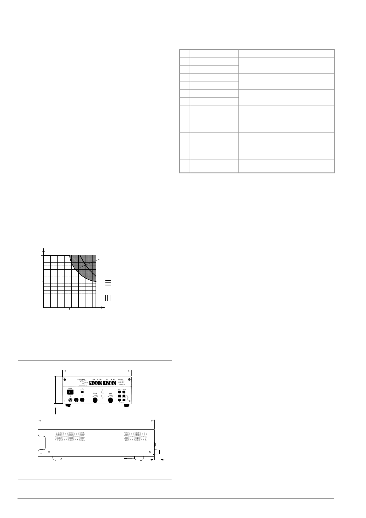
1.5 Technical Data
U/V
U
nom
I / A
I
nom
0
0.5 I
nom
P
nom
Short-Term
Working Range
Voltage Setting
Current Setting
0.5
U
nom
Range
Range
380.5
17
14 88
221.5
Dimensions in millimeter
1.5.1 General Data
Power Supply
Connection Input: 10 A IEC inlet plug
Output: 10 A IEC inlet socket,
Line voltage 230 V ~ +10 -15%, 47 to 63 Hz
Power consumption See chapter 1.4.3
Inrush Current Max. 50 A
Mains fuse 1 ea. T 4 A / 250 V (6.3 x 32 mm, UL)
internal: 1 ea. T 5 A 250 V (5 x 20 mm)
Output
Connection
Output Front panel, 2 ea. 4 mm safety jacks
Rear , 6-pole plug-in screw terminal block
Sensor Rear panel, included in 6-pole plug-in
screw terminal block
Analog interface Rear, 11-pole plug-in screw terminals
Regulator type Primary switched-mode regulator with
BET technology
Operating modes Adjustable constant voltage / constant
current source with automatic sharp
transition
Output isolation Floating output with “safe electrical
separation” from the mains input and
computer interfaces
Max. allowable potential, output–ground:
120 V, capacitance, output–ground
(housing) 60 nF
Output operating range
without switch,
without fuse
S
Analog Interface
Connection 11-pole plug-in screw terminal block
Reference potential Output minus pole, floating TRG input
Connector pin assignments:
Pin Designation Function
1SIG1 OUT
2SIG2 OUT
3TRG IN –
4TRG IN +
5 +15 V
6AGND
7U
– Analog, inverting voltage control input
set
+ Analog voltage control input
8U
set
+ Analog current control input
9I
set
10 U-MON Output voltage measuring output
11 I-MON Output current measuring output
Digital, programmable, open-collector outputs (max.
30 V / 20 mA)
Digital, programmable control input
(low: < 1.0 V, high: 4 ... 26 V), potential-free
Auxiliary voltage, +15 V / max. 50 mA
reference point, connected to -output
(0 ... –5 V correspond to 0 ... U
(0 ... +5 V correspond to 0 ... U
(0 ... +5 V correspond to 0 ... I
(0 ... 10 V correspond to 0 ... U
(0 ... 10 V correspond to 0 ... I
, Ri = 10 k)
nom
, Ri = 10 k)
nom
, Ri = 10 k)
nom
, Ri = 9.8 k)
nom
, Ri = 9.4 k)
nom
Addressable V.24 – RS 232C Interface
Input 9-pin subminiature socket connector
Output 9-pin subminiature plug connector
Operating mode half-duplex, asynchronous, XON / XOFF
Transmission speed adjustable from 50 to 19,200 bits per second
Device address selectable from 0 to 30 or UNL (unlist)
Max. Setting Rate approx. 15 settings per second
Max. Sampling Rateapprox. 7 measurements per second
IEC 625 – IEEE 488 Interface (optional)
Connection 24-pin socket connector
per IEC 625.1, IEEE488.1
Interface SH1 SOURCE HANDSHAKE
functions handshake source function
AH1 ACCEPTOR HANDSHAKE
handshake sink function
T6 TALKER
talker function with serial polling
and automatic unlisting,
no secondary address and no
Short-term range:
If lengthy operation in the short-term
range occurs, overtemperature protection may be triggered resulting in output
shutdown (see also short-term power in
chapter 1.5.3).
talk-only operation
L4 LISTENER
listener function with automatic
unlisting, no secondary
address and no listen-only operation
SR1 SERVICE REQUEST
service request function
RL1 REMOTE / LOCAL
remote to local switching
function with disabling
DC1 DEVICE CLEAR
reset function including selected
device clear
PP1 PARALLEL POLL
parallel polling function with remote
configuring
DT1 DEVICE TRIGGER
trigger function
C0 No controller function
E1/2 Open collector driver
Codes / formats Per IEEE 488.2
Device address Selectable from 0 to 30 or UNL (unlist)
Figure 1.5 Dimensional Drawing (benchtop device)
Max. setting rate Approx. 40 settings per second
Max. sampling rate Approx. 15 measurements per second
8 GMC-I Messtechnik GmbH
Page 9

Electrical Safety
Safety class I
Overvoltage
category II for mains input
I for output and interfaces
Fouling factor 2
Earth leakage
current 2.5 mA, typ.
IEC 61010-1:1990 + A1:1992 / DIN EN 61010-1: 1993 /
VDE 0411-1:1994
DIN VDE 0160:1988 + A1:1989 class W1
EN 60950:1992 / VDE 0805:1990
Protection IP 20 for housing per
IEC 529:1989,
EN 60529:1991,
VDE 0470-1:1992
Electrical isolation Test voltage
Mains/output–PE 1.35 kV~
Mains–output 2.7 kV~ (type test: 3.7 kV ~)
Electromagnetic Compatibility (EMC)
Product standard EN 61326-1:1997 + A1: 1998
Interference
emission EN 55022:1998 class A
Interference
immunity EN 61000-4-2:1995, feature A
EN 61000-4-3:1996 + A1:1998,
feature B
EN 61000-4-4:1995, feature B
EN 61000-4-5:1995, feature B
EN 61000-4-6:1996, feature B
EN 61000-4-11:1994, feature B
Ambient Conditions
IEC 68-2-6 (’90) Vibration resistance
10 ... 55 Hz, 0.3 mm, 1 octave / min.,
3 x 30 min.
IEC 68-2-27 (’89) Impact resistance
(15 g, 11 ms, semi-sinusoidal,
3 x 6 shocks)
Temperature Operation: 0 to 50° C,
range current derating at > 40° C
(see also chapter 1.5.3)
Storage: -25 to +75° C
Relative humidity Operation:
75%, no condensation allowed
Cooling With integrated fan
Inlet vent: side panel
Outlet vent: rear panel
1.5.2 Mechanical Data
Type Benchtop device, suitable for rack
Dimensions See also dimensional drawing in
(W x H x D) Benchtop device:
Weight Approx. 2.8 kg
mounting
Figure 1.5
221.5 x 102 x 397.5 mm
For 19" rack: ½19" x 2 standard height
units x 400 mm
IEEE 488 interface (optional):
approx. 0.1 kg
GMC-I Messtechnik GmbH 9
Page 10

1.5.3 Electrical Data
Electrical Data for 120 W Models
Unless otherwise specified, all entries are maximum values and apply within an operating
temperature range of 0 to 50C, within the nominal power range and the nominal line
voltage range of 230 V
Percentages make reference to the respective setting value or measured value.
Description (abbreviated name) SSP 120-20 SSP 120-40 SSP 120-80
Typ e 32 N 20 RU 10 P 32 N 40 RU 6 P 32 N 80 RU 3 P
Nominal Output Data Voltage setting range 0 ... 20 V 0 ... 40 V 0 ... 80 V
Output Characteristics
Setting resolution
[display (< 10.00 / 10.00), remote]
Overall setting accuracy at 23 ± 5° C
including system deviation (load / mains)
Static system deviation
with 100% load fluctuation
Static system deviation
with 10% line voltage fluctuation
Residual ripple
Ua > 5% U
Common mode noise (10 Hz ... 1 MHz) 0.5 mA
Settling time (voltage)
with load step of 10 ... 90% I
Under and overshooting with load step of 50 A / ms (Typical values) I = 80% 400 mV 400 mV 800 mV
Response time (voltage)
with setpoint jump from 0 100%
with setpoint jump from 100% 0
Response time (current)
with setpoint jump from 0 100%
with setpoint jump from 100% 0
Measured Value Displays (4-place)
Measuring resolution
[display (< 10.00 / 10.00), query]
Measuring accuracy at 23 ± 5° C
for values > 0.1% of the nominal value
Protective Functions
Output overvoltage protection, trigger value Setting Range
Reverse polarity protection load capacity Continuous 10 A 6 A 3 A
Reverse voltage withstand capacity Continuous 40 V 80 V 100 V
General
Power supply
Power consumption At nominal load
Efficiency At nominal load > 70% > 80% > 80%
Switching frequency Typical 200 kHz 200 kHz 200 kHz
Article Number K320A K321A K322A
1)
Specified values are increased by a factor of approximately 1.2 within the functional range for line voltage, namely -10% to -15%.
nom
1)
10% after a warm-up period of 30 minutes.
Short-term power where t < 90 s / Tu 25° C max. 200 W max. 240 W max. 240 W
1)
1
1)
1
1)
nom
Current setting range 0 ... 10 A 0 ... 6 A 0 ... 3 A
Continuous power at Tu 40° C
max. 120 W max. 120 W max. 120 W
Current derating where Tu > 40° C -0.25 A / K -0.15 A / K -0.07 A / K
Voltage
Current
Voltage
Current
Voltage
Current
Voltage
Current
Voltage (10 Hz ... 10 MHz)
Current (10 Hz ... 1 MHz)
To le ra n ce
(Typical values) I = 80%
To le ra n ce
No-load / nominal load
No-load / nominal load
To le ra n ce
short-circuit / nominal load
short-circuit / nominal load
Voltage
Current
Power
Voltage
Current
Power
Setting resolution
Setting accuracy
Line voltage 230 V~ +10 / 15%
In standby mode
With maximum short-term power
5 mV / 10 mV, 5 mV
2.5 mA
0.15% +30 mV
0.4% +35 mA
15 mV
20 mA
5 mV
8 mA
10 mV
eff
25 mA
eff
eff
40 mV
200 s
40 mV
1 ms / 1 ms
1 ms / 1 ms
100 mA
< 5 ms / < 5 ms
< 5 ms / < 5 ms
2 mV / 10 mV, 2 mV
1 mA, 1 mA
0.1 W, 0.1 W
0.15% + 30 mV
0.4% + 25 mA
0.55% + 0.5 W
0 ... 25 V
0.1 V
2% + 0.2 V
47 ... 63 Hz
280 VA, 180 W
45 VA, 15 W
450 VA
10 mV
2 mA
0.15% +40 mV
0.5% +20 mA
10 mV
10 mA
5 mV
5 mA
10 mV
eff
20 mA
eff
0.5 mA
eff
80 mV
200 s
80 mV
1 ms / 1 ms
1 ms / 1 ms
60 mA
< 5 ms / < 5 ms
< 5 ms / < 5 ms
10 mV, 4 mV
0.6 mA, 1 mA
0.1 W, 0.1 W
0.15% + 40 mV
0.5% + 15 mA
0.65% + 0.6 W
0 ... 50 V
0.2 V
2% + 0.4 V
230 V~ +10 / 15%
47 ... 63 Hz
280 VA, 170 W
45 VA, 15 W
500 VA
20 mV
1 mA
0.15% +80 mV
0.5% +10 mA
10 mV
10 mA
5 mV
5 mA
10 mV
eff
10 mA
eff
0.5 mA
eff
160 mV
200 s
160 mV
4 ms / 4 ms
4 ms / 4 ms
30 mA
< 10 ms / < 10 ms
< 10 ms / < 10 ms
10 mV, 8 mV
0.5 mA, 1 mA
0.1 W, 0.1 W
0.15% + 80 mV
0.5% + 10 mA
0.65% + 0.8 W
0 ... 100 V
0.4 V
2% + 0.8 V
230 V~ +10 / 15%
47 ... 63 Hz
280 VA, 170 W
45 VA, 15 W
500 VA
10 GMC-I Messtechnik GmbH
Page 11

Electrical Data for 240 and 320 W Models
Unless otherwise specified, all entries are maximum values and apply within an operating
temperature range of 0 to 50C, within the nominal power range and the nominal line
voltage range of 230 V
10 % after a warm-up period of 30 minutes.
Percentages make reference to the respective setting value or measured value.
SSP 240-20 SSP 240-40 SSP 240-80 SSP 320-32
32 N 20 RU 20 P 32 N 40 RU 12 P 32 N 80 RU 6 P 32 N 32 RU 18 P
0 ... 20 V 0 ... 40 V 0 ... 80 V 0 ... 32 V
0 ... 20 A 0 ... 12 A 0 ... 6 A 0 ... 18A
max. 240 W max. 240 W max. 240 W max. 320 W
max. 320 W max. 360 W max. 360 W max. 430 W
-0.5 A / K -0.3 A / K -0.15 A / K -0.5 A / K
5 mV / 10 mV, 5 mV
5 mA / 10 mA, 5 mA
0.15% +40 mV
0.5% +70 mA
25 mV
30 mA
5 mV
8 mA
15 mV
eff
50 mA
eff
0.5 mA
eff
40 mV
600 s
10 mV
3.33 mA / 10 mA, 3.33 mA
0.15% +45 mV
0.5% +45 mA
18 mV
30 mA
5 mV
8 mA
15 mV
eff
25 mA
eff
0.5 mA
eff
80 mV
300 s
20 mV
2 mA
0.15% + 80 mV
0.5% +25 mA
18 mV
15 mA
5 mV
5 mA
15 mV
eff
20 mA
eff
0.5 mA
eff
160 mV
200 s
50 mA
450 mV 450 mV 800 mV 450 mV
40 mV
1 ms / 1 ms
1 ms / 1 ms
200 mA
< 5 ms / < 5 ms
< 5 ms / < 5 ms
2 mV / 10 mV, 2 mV
2 mA, 10 mA, 2 mA
0.15% +40 mV
0.5% +70 mA
0.65% +1.4 W
80 mV
1 ms / 1 ms
1 ms / 1 ms
120 mA
< 5 ms / < 5 ms
< 5 ms / < 5 ms
10 mV, 4 mV
2 mA / 10 mA, 1.2 mA
0.15% +40 mV
0.5% +25 mA
0.65% +1 W
160 mV
4 ms / 4 ms
4 ms / 4 ms
60 mA
< 10 ms / < 10 ms
< 10 ms / < 10 ms
10 mV, 8 mV
0.6 mA, 1 mA
0.15% + 80 mV
0.5% +15 mA
0.65% +1.2 W
10 mV
5 mA / 10 mA, 5 mA
0.15% +50 mV
0.5% +70 mA
30 mV
40 mA
10 mV
20 mA
30 mV
eff
(Ua > 10%U
eff
0.5 mA
eff
64 mV
500 s
64 mV
1 ms / 1 ms
1 ms / 1 ms
180 mA
< 5 ms / < 5 ms
< 5 ms / < 5 ms
10 mV, 4 mV
2 mA, 10 mA, 2 mA
0.1 W, 0.1 W
0.15% +40 mV
0.5% +70 mA
0.65% +1.4 W
nom
)
0 ... 25 V
0.1 V
2% +0.2 V
0 ... 50 V
0.2 V
2% +0.4 V
0 ... 100 V
0.4 V
2% + 0.8 V
20 A 12 A 6 A 18 A
40 V 80 V 100 V 64 V
230 V~ +10 / 15%
47 ... 63 Hz
510 VA, 350 W
45 VA, 15 W
620 VA
230 V~ +10 / 15%
47 ... 63 Hz
500 VA, 340 W
45 VA, 15 W
690 VA
230 V~ +10 / 15%
47 ... 63 Hz
500 VA, 340 W
45 VA, 15 W
690 VA
> 68% > 70% > 70% > 69%
200 kHz 200 kHz 200 kHz 200 kHz
K330A K331A K332A K334A
1)
Specified values are increased by a factor of approximately 1.2 within the functional range for line voltage, namely -10% to -15%.
0 ... 40 V
0.2 V
2% +0.4 V
230 V~ +10 / 15%
47 ... 63 Hz
650 VA, 460 W
50 VA, 15 W
770 VA
GMC-I Messtechnik GmbH 11
Page 12
2 Initial Start-Up
Warning!
Attention!
!
ANALOG INTERFACE OUTPUT
OUTIN RS 232
230V 5
FUSE T4
➁
➂
➁
Interface
Module
Ribbon
Cable
➁
➀
➀
➁
19“ Dummy Plate
19“ Abutment
➃
19'' Connector Plate
19'' Abutment
➃
➃
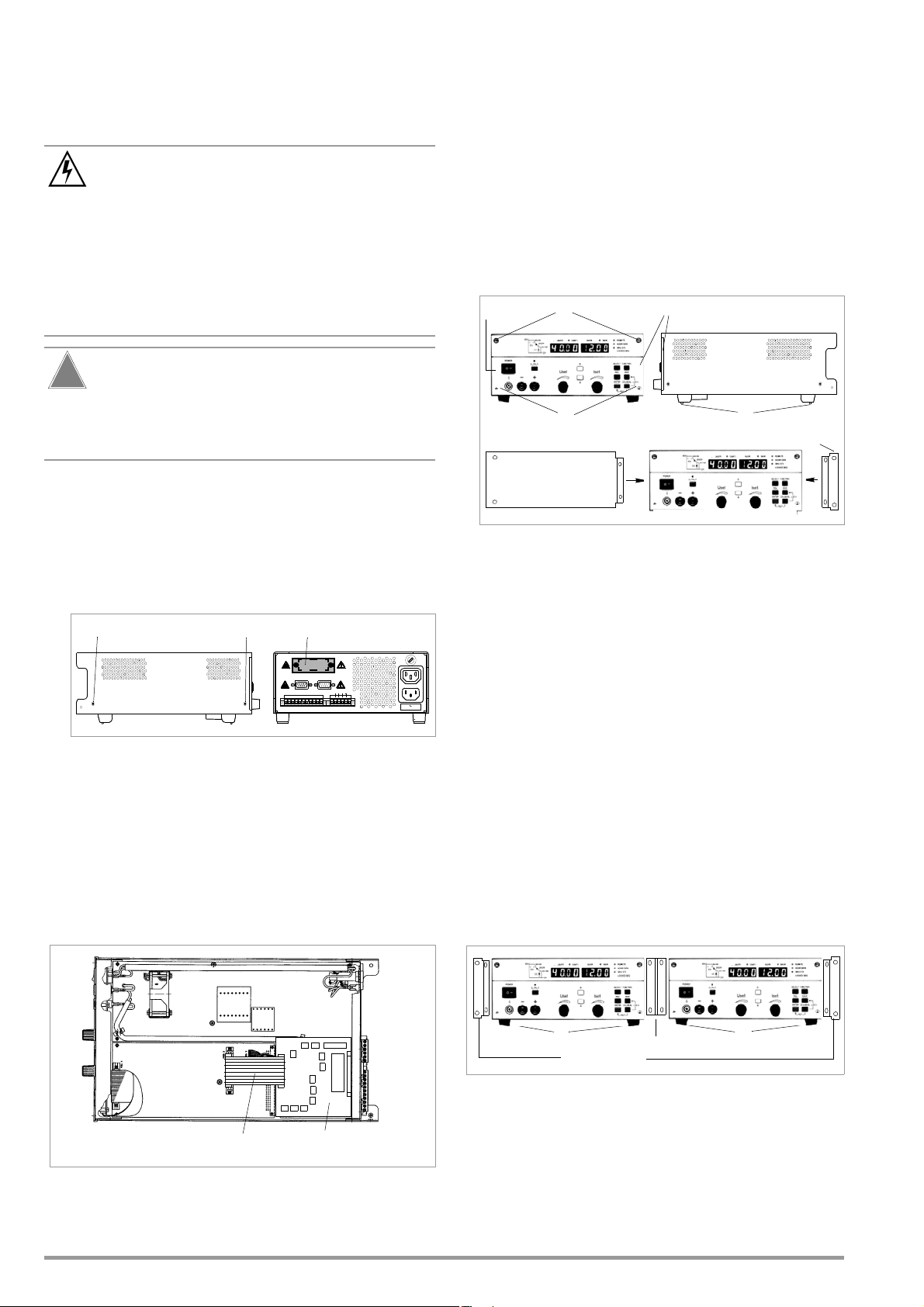
2.1 Preparing for Operation
2.1.1 Installing the IEEE 488 Interface Module
2.1.2 Installation to 19'' Device Racks
The SSP KONSTANTER housing allows for use as a benchtop
instrument, as well as for installation to a 19'' rack. One
KONSTANTER and a cover plate, or two devices next to each
other can be installed to the rack.
The benchtop instrument can be quickly retrofitted for rack
mounting.
The KONSTANTER must be disconnected from the
mains before installing the interface module. Switch the
KONSTANTER off, and then pull the mains plug from the
outlet. Wait at least 5 minutes before opening the
KONSTANTER, in order to assure that the capacitors
have been discharged to a safe voltage level.
Capacitors may otherwise be charged with life
endangering voltage, and coming into contact with them
may result in severe injury.
The interface module may be damaged by electrostatic
discharge. Observe guidelines for handling electrostatic
sensitive devices. Do not touch electrical contacts or PCB
components.
➀ Disconnect the KONSTANTER from the mains, and pull the
mains plug from the outlet. Wait for at least 5 minutes in
order to assure that the capacitors have been adequately
discharged.
➁ Loosen the 4 screws in the housing cover and lift the cover
off.
➂ Unscrew the cover plate at the left-hand side of the rear
housing panel. Save the screws for use in the next step..
Retrofit for Rack Mounting a Single Device
Use the accessory adapter: 19'' adapter 1 x 32 N.
This accessory components includes a 19'' abutment and a 19''
blanking plate.
➀ Loosen the 4 screws at the KONSTANTER front panel.
➁ Pull out the filler strips from the left and right sides.
Figure 2.1.2 aRack Installation of a Single KONSTANTER
➂ Replace the filler strips with the 19'' abutment on one side,
and with the 19'' blanking plate on the other side, and
secure them with the four screws.
➃ Unscrew the feet from the bottom of the housing. Remove
the rubber inserts from the feet to this end. The screws are
then exposed.
➄ Now install the KONSTANTER to the rack. Save all loose
parts for possible future use.
Figure 2.1.1 a Opening the KONSTANTER Housing
the rack. The guide rails, as well as the front panel mounting
screws used to secure the KONSTANTER, are rack-specific and
The KONSTANTER must be attached to guide rails at one side of
➃ The interface module:
must be procured from your rack supplier.
With the ribbon cable facing forward, push the interface module
through the housing rear panel and into the device interior.
Securely screw the sheet metal cover on the interface
module to the housing rear panel from the outside. Use the
two screws referred to in step➂.
➄ Insert the plug connector from the interface module into the
connector strip on the primary printed circuit board. Do not
twist the ribbon cable.
Retrofit for Rack Mounting Two KONSTANTERs
Use the accessory adapter: 19'' adapter 2 x 32 N.
This accessory component includes two 19'' abutments and one
19'' connector plate.
➀ Loosen the 8 screws at the KONSTANTER front panels.
➁ Pull out the filler strips from the left and right sides of each
device.
Figure 2.1.2 b Rack Installation for Two KONSTANTERs
➂ Replace the filler strips with the 19'' abutments at the far left
and far right, and with the 19'' connector plate in the middle,
and secure them with the eight screws.
Figure 2.1.1 b Installing the Interface Module
➅ Return the housing cover and secure it with the four screws.
The KONSTANTER can now be connected as usual.
12 GMC-I Messtechnik GmbH
Screw both housings to the through-holes and threads in
the plug protector at the rear.
Page 13

➃ Unscrew the feet from the bottom of the housing. Remove
Attention!
!
Warning!
the rubber inserts from the feet to this end. The screws are
then exposed.
➄ If you would like to electrically connect the two
KONSTANTERs, use the “mains jumper cable” and “RS 232
bus cable” accessories.
➅ Install the two devices to the rack. Save all loose parts for
possible future use.
The KONSTANTERs must be attached to guide rails at both sides
of the rack. The guide rails, as well as the front panel mounting
screws used to secure the KONSTANTERs, are rack-specific and
must be procured from your rack supplier.
2.1.3 Combining Benchtop Devices
Up to 3 benchtop KONSTANTERs can be stacked in combination
(see also chapter 5 for electrical connection options via the analog
interface).
➀ Unscrew the feet from the bottom of the housing. Remove
the rubber inserts from the feet to this end. The collar screws
are then exposed.
Four oblong slots now become visible at the bottom of the
housing.
➁ Turn the 4 collar screws from the feet into the 4 threaded
holes on the top of the other device housing. Save the 4
retaining washers and feet for possible future use.
➂ Set the KONSTANTER without feet onto the top of the other
KONSTANTER. The screws from the bottom KONSTANTER
must protrude through the oblong slots in the base of the
other KONSTANTER. Carefully push the top KONSTANTER
back until the screws snap into place.
➃ Screw the two KONSTANTERs together via the through-
holes and threads in the plug protector at the back. The top
KONSTANTER is thus secured against shifting.
➄ If you would like to electrically connect the two
KONSTANTERs, use the “mains jumper cable” and “RS 232
bus cable” accessories.
2.1.4 Connection to the Mains
Observe WARNING I!
Before switching the KONSTANTER on, is must be
assured that available mains power complies with the
supply power values specified at the mains connection
on the back of the device.
The KONSTANTER requires 230 V ~ supply power. Connect the
mains inlet plug at the rear panel to a mains outlet with earthing
contact using the included power cable.
Rated power consumption is specified on the serial plate at the
bottom of the KONSTANTER.
A mains outlet is included above the mains inlet plug for looping
mains power through to an additional KONSTANTER.
This mains outlet can neither be switched on and off, nor is it protected
with a fuse.
If mains power is looped through, make sure that overall
current consumption does not exceed 10 A at the
incoming supply lines!
Suitable “mains jumper cables” are available as
accessories (see order information on last page).
2.1.5 Connecting Power Consumers
The output leads are connected either at the front panel with
4 mm safety plugs to the “” and “” safety jacks, or at the rear
panel to the “” and “” outputs at the 6-pole screw terminal.
If loads are connected to both the front and the rear panel (not
allowed in the event of parallel connection due to danger of
overload!), constant voltage regulation applies to the terminals at
the rear panel. There are two terminals each for “” and “” for
load connection at the rear panel.
In the case of load current of greater than 10 A, these terminals must
be parallel connected due to the specified contact rating.
Make sure that the utilized cables have an adequate cross-section,
and that polarity is not reversed. It is advisable to twist the output
leads and to identify polarity at both ends.
The yellow-green safety jack at the front panel is connected to
PE, and can be used to connect ground cables or cable shield, or
can be used as an earth connection point for one of the output
poles.
2.1.6 Connection to Computer Interfaces
If the KONSTANTER is used within computer controlled systems,
one of the two connections described below must be established
via the appropriate interface.
Comments
The KONSTANTER cannot be remote controlled via both
interfaces simultaneously. The interface which first initiates
action after mains power has been switched on is activated,
and the other remains inactive.
In order to assure that existing bus activity is not interfered
with, all affected KONSTANTERs should be switched off while
establishing the bus connection.
Both interfaces are equipped with a common ground (GND),
and are electrically isolated from the output in accordance with
specified electrical safety regulations.
Interface configuration is described in chapter 4.7.4.
RS 232C Interface
Most controllers include two serial ports, which are commonly
designated COM1 and COM2, and which are equipped with 25 or
9-pin subminiature plug connectors.
A suitable cable with a length of approximately 2 meters is
available as an accessory for connecting the KONSTANTER and
the controller. Cables with other lengths are commercially
available. Appropriate adapters are available as well, in the event
that your controller is equipped with a 25-pin plug connector.
If you would like to fabricate the connector cable yourself, you’ll
need a 3-conductor shielded cable in order to establish
connection as shown in Figure 2.1.6 a.
GMC-I Messtechnik GmbH 13
Page 14
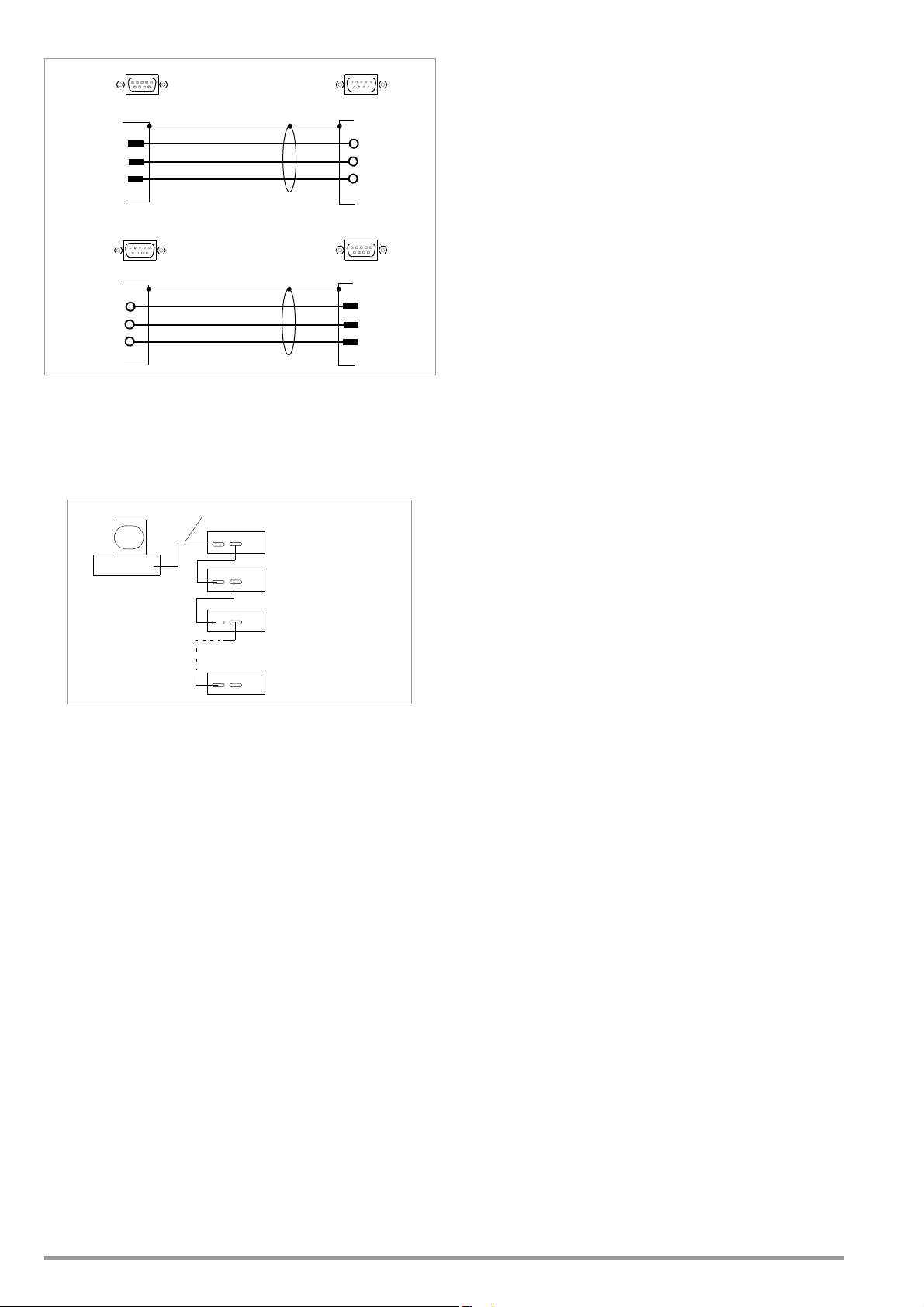
Figure 2.1.6 a Pin Assignments for 9-Pin Plug and
TxD_IN 2
3
5
RxD_IN
GND_IN
2 RxD
3 TxD
5 GND
SSP
9-pin Plug9-pin Socket Connector
RxD_OUT 2
3
5
TxD_OUT
GND_OUT
2 TxD_IN
3 RxD_IN
5 GND_IN
9-pin Plug 9-pin Socket Connector
SSP
OUT
IN
RS 232
RS 232
PC/Controller
SSP
IN
RS 232
COM1/COM2
IN OUT
IN OUT
IN OUT
IN OUT
Accessory:
RS 232 Bus Cable, 0.4 meters
Accessory: RS 232 Bus Cable, 2 meters (for example)
Socket Connectors
The serial interface furnished with this KONSTANTER series is
addressable. Up to 30 KONSTANTERs can be addressed via this
interface.
Data Queries
If a device (slave) is requested to return data to the controller, it
may not be addressed in the interim. In other words, the controller
must wait until all requested data have been fully received. No
data may be transmitted to any other devices during this period of
time.
In the case of multiple device serial operation, good timing must be
assured. Data collision is thus avoided, which may result in
interruption of data transfer and deletion of output buffer
contents.
If the slave does not respond within a specified period of time
(TIMEOUT), the controller can try to synchronize the device with a
universal command, or execute a reset and request the required
data once again.
IEEE 488 Interface
Up to 15 IEC bus controlled devices (including the controller)
can be interconnected to create a system.
These devices are connected to the bus with suitable,
commercially available cables with 24-pin plug connectors.
If your IEC bus system is equipped with the previously
common 25-pin subminiature plug connectors, you’ll need a
suitable adapter cable.
In order to assure reliable data transfer, the cable length
between any two devices should not exceed 2 meters, and
overall length should not exceed 15 meters.
Double shielded connector cable is recommended if the
KONSTANTERs are operated in proximity to strong sources of
interference or their power cables.
2.2 Switching the Instrument On
After the described preparations have been completed, the
device can be switched on.
Press the mains switch [1] at the front panel until it snaps into
place in order to turn the device on.
Power-Up Test
The microprocessor included in the device then starts a power-up
Figure 2.1.6 b Interconnection via the Serial Interface
If RS 232 communication is to be expanded to several
KONSTANTERs, additional arrangements must be made
regarding data protocols.
Addressing
A separate address is assigned to each interconnected
KONSTANTER. If the KONSTANTER receives its own address, it
is switched to the “addressed” status after which it accepts all
subsequent commands and data, until it is unlisted upon receipt
of a different device address.
In compliance with IEEE 488, an address range of 0 to 31 is used,
although address 31 is reserved as a general unlist command
(UNL). The serial interface’s device address is thus identical to the
address of the optional IEEE 488 interface (if included).
Universal Commands
In addition to the command
Addr xxDevice address,
other general commands can be used which are accepted
without previous addressing.
*TRG Trigger command, synchronization
DCL Device clear
IFC Interface clear
Explanations of these commands and their syntax are included in
chapter 6.
14 GMC-I Messtechnik GmbH
test. The following operations are performed during the test
routine (duration approximately 8 seconds):
– Reset all functional units (except battery-backed setup
memory)
– ROM test
–RAM test
– Initialize computer interfaces if installed
– Ascertain device type
– Check the A-D converter timer
– Recall last settings if required
The “LOCKED/SEQ” LED [12] blinks while this routine is running,
and all other LEDs and all digital display segments light up
(display test). If the device has been equipped with the optional
“IEEE 488 computer interface”, the selected IEC bus device
address then appears briefly at the display (e.g. “Addr 12”).
After successful completion of the self-test, the READY lamp is
continuously illuminated and the display is switched to measured
value indication for voltage (Uout) and current (Iout).
If this status is not achieved despite correctly selected device
address (0 to 30), even after repeatedly switching the device on
and off with abbreviated self-test, the device is probably
defective. If this is the case, contact your local representative.
Page 15

Abbreviated Power-Up Test
In order to shorten power-up time, or if problems occur with the
normal power-up test, an abbreviated power-up test can be
used:
With the device switched off, press and hold the <ENTER>
key.
Turn the mains switch on.
Release the <ENTER> key after approximately 1 second.
If this procedure is used, only essential initialization steps are run
during power-up.
After initial power-up, the device has the following basic
configuration:
Interface functions Standard “pon” status
Device functions
– Output status Inactive
– Voltage setpoint 0 V
– Current setpoint 0 A
– Voltage setting limit Nominal output voltage
– Current setting limit Nominal output current
– OVP trigger value 25 V (for 20 V models)
50 V (for 40 V models)
100 V (for 80 V models)
– Current limiting mode Limiting without shutdown
– Shutdown delay 0 ms
– TRIGGER input Inactive
– Min-Max measured value memory Off
– Power ON mode Reset configuration
– Manual operation Enabled
– Memory contents Deleted
The desired settings can be selected starting with this basic
configuration.
After a warm-up period of approximately 30 minutes, the
instrument operates at maximum accuracy.
When the device is powered up again at a later point in time, active
device configuration depends upon the last setting selected for
the POWER_ON function (—> page 69):
– Default settings or
– Last used device settings or
– Last used device settings with inactive output
Power-Up with RESET
In order to assure that the connected power consumer is not
endangered by any previous device settings, the device can be
initialized with the “POWER_ON RST” function by pressing and
holding the <CE/LOCAL> key during the power-up routine.
In order to switch the device off, activate the mains switch one again.
The device is then disconnected from mains power and the
output is deactivated. The last device configuration, as well as any
settings which have been saved to battery-back configuration
memory, are retained.
Caution!
Avoid switching the device on and off in a rapid, repeated fashion. This
temporarily impairs the effectiveness of the inrush current limiting
function, and may result in a blown fuse.
GMC-I Messtechnik GmbH 15
Page 16
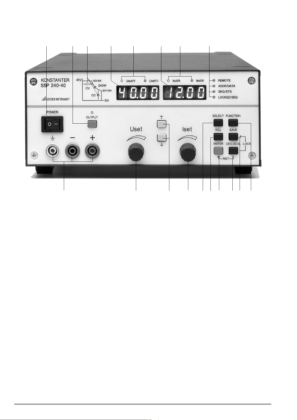
3 Controls, Display Elements and Terminals
12356 89 12
171615141311 1074 18
Note: Numbers in brackets make reference to the figures included below.
[1] Mains Switch <POWER>
For turning the KONSTANTER on and off
After switching the KONSTANTER on, a self-test is performed
with a duration of approximately 8 seconds. After successful
completion of the self-test, the KONSTANTER briefly displays
its interface address and the version number of the installed
firmware, one after the other. The POWER-ON function then
configures the device with predetermined settings and the
device is ready for use.
When the KONSTANTER is switched off, it is disconnected from
mains power and the output is immediately deactivated. The last
device configuration, as well as any settings which have been
saved to battery-backed setup memory, are retained.
[2] Output On-Off Key <OUTPUT>
The power output can be activated and deactivated by
pressing the <OUTPUT> key. The red LED above the <OUTPUT>
key is illuminated as long as the output is active.
No significant output voltage overshooting occurs when the
output is activated and deactivated.
Activation sequence:
If the power output is activated, current and voltage are initially
set to “0” for transition from the “highly resistive” state.
Setpoints do not become active until after this transition has
been completed.
Deactivation sequence:
Current is set to 0 A and voltage to 0 V for approximately
350 ms. A sink is thus activated which discharges the output
capacitors to the greatest possible extent. The sink is then
deactivated and the output becomes highly resistive. However,
the output terminals are not electrically isolated.
[3] Control Mode, Protective Function and Status Displays
No LEDs light up: Output has not been activated
LEDs lights up:
Indicates the output’s operating status (control mode) if it has
been activated:
Green CV LED Constant voltage regulation (Uout = Uset)
Green CC LED Constant current regulation (Iout = Iset)
Blinking LED:
Indicates the reason for automatic deactivation of the output
Green CV LED OVP (overvoltage protection)
Overvoltage protection has been triggered,
because output voltage has exceeded the
selected trigger value OVP / OVSET.
Possible causes:
☞ Voltage setpoint USET has been set too high manually,
memory recall, programming error or Uset control signal to
the analog interface
☞ Voltage transients caused, for example, by switching
inductive power consumers (perhaps too little difference
between selected USET and OVSET values)
☞ Unipolar power recovery from the connected consumer
(e.g. DC motor)
16 GMC-I Messtechnik GmbH
Page 17

☞ During auto-sensing: Sensing lead polarity is reversed, or an
output lead is/was interrupted or was not taken into
consideration when adjusting OVSET, so that the voltage at
the output terminals which is relevant for the OVP function is
increased by the amount to be compensated for at both leads,
and is higher than USET voltage as controlled by the
sensors at the load side (too little difference between
selected USET and OVSET values).
☞ Parallel connected voltage sources
Green CC LED OCP (overcurrent protection)
Overcurrent protection is active.
If the OCP ON function has been activated,
the output was operated for a duration of
t > DELAY in the current limiting mode
(current regulation). The output has been
deactivated.
Possible causes:
☞ Current setpoint ISET has been set too low manually, memory
recall, programming error or Iset control signal to the
analog interface
☞ Current transients caused by switching inductive
consumers (DELAY time may be set too low)
Yellow Pmax LED OTP (overtemperature protection)
Electronic power limiting has been
(overload! Pout > Pnom).
Possible causes:
triggered
☞ Impaired cooling, e.g. air inlet or exhaust vents are
obstructed.
☞ Excessive ambient temperature
The KONSTANTER is capable of continuously supplying
nominal power at ambient temperatures of up to 50 °C
(measured at the air inlet vents). Approximately 120 to
130% nominal power can be drawn intermittently
(triggering point for electronic power limiting). Continuous
operation at these levels may cause triggering of the
overtemperature protection function.
☞ The fan has failed.
☞ A device error or defect has occurred.
After the cause of triggering has been eliminated, the output can be
reactivated.
[4] Output
Selected constant voltage or constant current is available from
the safety jacks at the front panel.
blue Negative output pole
red Positive output pole
yellow-green Earth connection point for the output or
shield terminal if shielded output leads are
used. The ground terminal is connected to
the housing and the earthing contact at the
mains connection.
The power consumer can also be connected to the OUTPUT
interface [22] at the rear panel.
[5] Left-Hand Display with [7]
[6] Display Parameter Indicators (LEDs)
As a default setting, the measured output voltage value Uout
appears in volts at the left-hand display.
The display can be switched to the momentary measured voltage
value Uset by slightly turning the voltage adjusting knob [5], or by
pressing the <ENTER> key.
The LEDs allocated to the display indicate which value is being
displayed (green LED = measured value, yellow LED = setting
value).
Uout / V (gr) = Measured output voltage value in V
Uset / V (ye) = Output voltage setpoint in V (blinking
indicates that the displayed value has not
yet been set)
If no adjustment is made for a period of 10 seconds during the
display of a setting value, the display returns to Uout
automatically.
Additional KONSTANTER functions can be selected with the
<SELECT>, <FUNCTION>, <RCL> and <SAVE> keys. The function
code or the parameter name appears at the left-hand display
in this case.
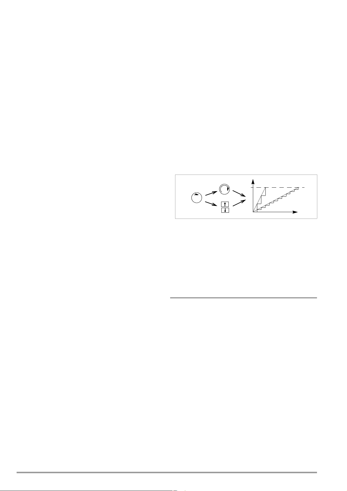
[7] Rotary Knob for Voltage Adjustment <Uset>
Voltage is adjusted in the usual fashion with the rotary knob.
However, the adjusting element is not a potentiometer, but
rather a rotary pulse encoder which generates 24 pulses per
revolution, whose setting resolution (step size per pulse) can
be set to either coarse, medium or fine with the <SELECT>
function. This allows for convenient, precise adjustment on the
one hand, and also assures that no change occurs to the
selected value when switching between remote control and
manual operation.
When the voltage adjusting knob is turned, the left display is
first switched to the Uset display and the current voltage
setpoint appears. After approximately 0.4 seconds, one of the
decimal places starts blinking at the display in order to indicate
selected adjusting sensitivity. From this point on, turning the
rotary knob changes the display value, and thus the setpoint
value, at the selected decimal place.
Clockwise rotation increases the value, and counterclockwise
rotation decreases the value.
If no adjustment is made for a period of 10 seconds, the
display automatically returns to the measured voltage value
Uout. The display can be immediately switched to the Uout
value by pressing the <CE/LOCAL> key.
☞ Detailed explanations are included in chapter 4.6.
[8] Right-Hand Display with [10]
[9] Display Parameter Indicators (LEDs)
As a default setting, the measured output current value Iout
appears in amperes at the right-hand display.
The display can be switched to the momentary current setpoint
Iset by slightly turning the current adjusting knob [8], or by
pressing the <ENTER> key twice.
The LEDs allocated to the display indicate which values are
being displayed (green LED = measured value, yellow LED =
setting value).
Iout/A (gr) = Measured current value in A
Iset / A (ye) = Current setpoint in A (blinking indicates that
the displayed value has not yet been set)
If no adjustment is made for a period of 10 seconds during the
display of a setting value, the display returns to Iout
automatically.
GMC-I Messtechnik GmbH 17
Page 18

Additional KONSTANTER functions can be selected with the
Attention!
!
<SELECT>, <FUNCTION>, <RCL> and <SAVE> keys. The
respective measured value or setting parameter appears at the
right-hand display in this case.
[10] Rotary Knob for Adjusting Current <Iset/A>
The same applies to this rotary knob, with reference to output
current, as is also the case with the voltage adjusting knob [5].
[11] Parameter Adjusting Keys and
The <> (increment) and <> (decrement) keys are used to
select or adjust all KONSTANTER functions and their
parameters.
☞ Detailed explanations are included in chapters 4.6, 4.7
and 4.14.
[12] Interface Displays: REMOTE, ADDR, SRQ, LOCKED
The respectively illuminated LED indicates the current
operating state of the computer interface:
REMOTE on: The KONSTANTER is being remote
controlled, front panel controls are
disabled.
ADDR/DATA on: The KONSTANTER has been addressed
and is receiving or transmitting data
(applies to IEC bus operation only).
SRQ/STS on: The KONSTANTER is transmitting a service
request.
LOCKED/SEQ on: Indicates that manual controls are disabled:
Front panel controls are disabled and
protected against unauthorized or
inadvertent change.
This display only applies to disabling of the
front panel controls by means of manual
operation or a control signal applied to the
TRIGGER input (for T_MODE LLO). It does not
indicate disabling of manual switching to
local control by means of the IEC bus LOCAL
LOCKOUT command.
blinking: Sequence mode display in
disabled and enabled state:
– Slow blinking: sequence in hold status
– Fast blinking: sequence in run status
Sequence mode display
LLO is displayed when any key or rotary
knob is activated (
and disabling:
l
ocal lockout).
[13] Function Selection Key <SELECT>
Selection of displayable measured values
Resolution of display values and setting values
☞ Detailed explanations are included in chapters 4.6, 4.7
and 4.8.
[14] Recall Key <RCL>
Recall of stored KONSTANTER settings, value pairs (Uset and
Iset) and any associated dwell time setting for possible
readjustment.
☞ Detailed explanations are included in chapter 4.10.
[15] <ENTER> Key
The <ENTER> key is used for several functions:
Execute selected functions
Acknowledge selected text parameters
Go to the next lowest function menu level
Switch the display from Uout / Iout to Uset / Iset with active
cursor
Setpoint changes are acknowledged with the <ENTER> key
in this mode.
Move cursor back and forth between Uset and Iset in the
Uset / Iset display
Activate the recalled memory location
☞ Detailed explanations are included in chapters 4.6, 4.7
and 4.12.
[16] <CE/LOCAL> Key
This key has several functions:
Abort an operation
Switching from remote to local control
Disable front panel controls
In combination with special functions
☞ Detailed explanations are included in chapter 4.13.
[17] Save Key <SAVE>
Saves device settings, value pairs (Uset and Iset) and any
associated dwell time. In the manual mode, this key also
fulfills the function of the STORE computer command.
Disabling of front panel controls in order to prevent
inadvertent or unauthorized changes to settings is only
possible in combination with the <CE/LOCAL> key.
☞ Detailed explanations are included in chapter 4.9.
[18] Function Selection Key <FUNCTION>
No special key is assigned to device functions which are
normally seldom adjusted or used. These functions are
controlled in a menu-driven fashion.
☞ A description of the menu and the procedure for setting all
functions and parameters is included in chapter 4.7.
[19] RS 232 Interface
☞ Detailed explanations regarding remote control of
KONSTANTER functions via the RS 232 serial interface are
included in chapter 2.1.3.
☞ Interface-specific commands are included in chapter 6.4.
[20] IEEE 488 Bus Connection
Connection for remote control of KONSTANTER functions:
☞ Detailed explanations are included in chapter 2.1.1.
☞ Interface-specific commands are included in chapter 6.4.
The electrical contacts of all interfaces are connected to
components which may be damaged by electrostatic
discharge. Neutralize potential differences between
yourself and the device by grasping the housing before
touching these contacts!
18 GMC-I Messtechnik GmbH
Page 19
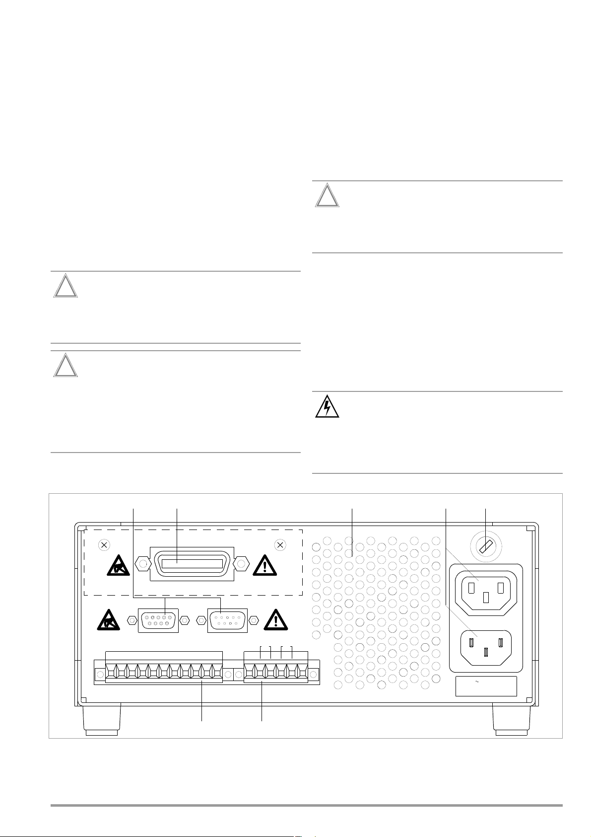
[21] Analog Interface
Attention!
!
Attention!
!
Attention!
!
Warning!
GOSSEN METRAWATT
IEC 625/IEEE 488 INTERFACE F. SSP-KONSTANTER BEST.NR. K380A
+
-
+
+
-
+
-
+
SENSE
-
+
SENSE
I-MON
U-MON
Iset
Uset
Uset
AGND
15V
TRG IN
TRG IN
SIG2 OUT
SIG1 OUT
ANALOG INTERFACE OUTPUT
OUT
IN
RS 232
230V 50-60Hz
FUSE T4/250V
19 20
21 22
23 24 25
The analog interface facilitates the following functions:
Remote adjustment of output voltage and current with
analog control voltages ranging from 0 to 5 V, or 5 to 0 V
☞ chapter 5.8 / chapter 5.4
External measurement or recording of output voltage and
current based on monitor signals, 0 to 10 V
☞ chapter 5.4 / chapter 5.5
Supply external controllers with +15 V auxiliary power
Linking of several devices for master-slave operation
☞ chapter 5.9 / chapter 5.10
Varying the internal output resistance value
☞ chapter 5.8
Control of a selected device function via the floating trigger
input
☞ chapter 5.7
The electrical contacts of this interface are connected to
components which may be damaged by electrostatic
discharge. Ground yourself by grasping the housing
before touching these contacts!
All of the control cables connected to the analog
interface should be shielded. Ground the shield directly
to the device using the shortest possible connection
lead. One of the threaded holes for the plug protector at
the rear panel can be used for this connection. Use a
suitable screw and washer to secure the connection and
assure good contact.
[22] OUTPUT Interface
The output interface offers two options:
Take constant voltage or constant current from the terminal
strip at the rear panel of the KONSTANTER.
Connect sensing leads for compensation of voltage drops in
the output leads
☞ chapter 5.3
[23] Exhaust Vents
The exhaust vents are required for regulating the temperature
inside the device. Warm air generated during operation of the
device is discharged via these vents with the help of a
temperature controlled fan.
The exhaust vents may not be closed or obstructed,
because heat accumulation inside the device may result
in malfunctioning, failure or damage to the
KONSTANTER.
[24] Mains Input
Mains input with looped through mains outlet for inlet plug. The
looped through mains outlets make it possible to directly
connect up to three devices using two short power cables with
inlet plugs. In this way, only one mains power cable is required
to operate all three devices.
[25] Mains Fuse
Fusing for the 230 V mains power input
All devices: T 4.0 A / 250 V (6.3 x 32 mm)
Only fuses of the type and nominal current rating
specified here may be used when replacing blown fuses.
Tampering with fuses or fuse holders is absolutely
prohibited (“repairing” fuses, short-circuiting fuse holders
etc.).
GMC-I Messtechnik GmbH 19
Page 20
4 Manual Operation and Device Functions
Uset / V
Uout
t
(1)
(2)
(3)
4.1 Menu Structure
After the power-up sequence has been completed, the device is
switched to the basic operating mode by means of which the
device’s basic functions can be executed, such as:
• Select desired output voltage Uset
• Select desired output current Iset
• Adjust allowable working range with soft-limits Ulim and Ilim
• Adjust overvoltage protection and overcurrent shutdown
Additional setup menus can be accessed with the function key.
These include:
• SEt (setup) extended Setup functions
• AnIF (analog interface) Analog interface settings
• SEq (sequence function) Sequence function settings
• bUS (computer interface) Interface configuration settings
• CAL (calibration menu) Balance the
After selecting the desired setup menu with the function key, the
respective menu level appears at the display.
The function and arrow keys are used to scroll through the
respective menu levels and select the desired settings.
The <CE/LOCAL> key can be used to shift back up one level at a
time, until the basic operating menu once again appears.
KONSTANTER
Initializing the Procedure
☞ Slightly turn (1) the Uset knob [7].
! The display is switched from Uout (measured voltage value)
to Uset (voltage setpoint). The decimal place for the selected
setting resolution blinks.
! The green Uout/V LED [6] goes out and the yellow Uset/V LED
[6] lights up. Continuous illumination of the Uset/V LED
indicates that values are activated immediately during
adjustment.
Selecting Resolution
! 3 step widths are possible: 0.01 V, 0.1 V or 1 V.
! The blinking decimal place [5] indicates which step width will
be used for setpoint adjustment.
☞ Repeatedly press the <SELECT> key [13] until the desired
decimal place blinks at the display.
Executing the Procedure
Values become immediately active during adjustment.
☞ Adjustment (2) with the Uset rotary knob [7]:
Clockwise rotation Increases the value
Counterclockwise rotation Decreases the value
All intermediate values are run through semi-linearly and are
read out to the output (assuming it is active).
4.2 Setting Output Voltage and Output Current
There are two ways to set output voltage and output current:
• Direct selection
Changes become immediately effective when this method is utilized,
assuming the output is active.
• Pre-selected settings
Output voltage or current is preset with the scroll keys to the
desired value. The selected value is activated at the output
after acknowledging with the <ENTER> key.
4.2.1 Direct Selection (rotary knobs and scroll keys)
The operating concept allows for direct selection of output
voltage and/or output current with the rotary knobs, with
immediate activation of the new values at the output.
In the default configuration, current output values appear at the
display with voltage at the left and current at the right-hand side.
This is indicated by means of the two LEDs above the display. If
the output is active (indicated by illumination of the red LED above
the <OUTPUT> key), the LEDs in the diagram indicate the control
state. Depending upon the selected output quantities and the
load situation, either output voltage or output current is regulated.
CV (constant voltage) indicates voltage regulation, and CC
(constant current) indicates current regulation.
If the working point is not within the allowable control range, the
power LED lights up.
The display can be switched to a representation of the
corresponding setpoint by slightly turning one of the rotary knobs
(Uset or Iset). This change is indicated by the respective LED
above the display. The blinking decimal place indicates the
resolution with which adjustment will take place. Resolution can
be adjusted with the <SELECT> key.
The setting can then be changed to the desired value with the
rotary knob.
As soon as the selected setpoints have been activated, they can
also be adjusted with the scroll keys, in which case resolution can
also be pre-selected.
Figure 4.2.1 a Continuous Adjustment of Uset
☞ Adjust (3) with the <> key or the <> key [11]
<> (increment) Increases the value
<> (decrement) Decreases the value
! Each time the key is pressed, output voltage is changed
by an amount which corresponds to the value selected
with the resolution setting function.
! Pressing and holding the respective key results in rapid
scrolling, regardless of the step width.
Attention! Uset may not be set to a value which exceeds Ulim!
Uset – Output Voltage
• Adjustment with the Uset rotary knob [7] is not enabled until 0.4
seconds after the digital display [5] has been switched to the
respective function. This delay time prevents inadvertent
changes to Uset during selection of the Uset display. The rotary
knob must be adjusted after this time period has elapsed in
order to change the Uset setting.
• After delay time has elapsed, output voltage is adjusted directly
as the knob is rotated, if the output is active. The currently
active value always appears at the display [5].
• If no adjustment is made for a period of 10 seconds, the
display automatically returns to the measured voltage value
Uout. The display can be immediately switched to the Uout
value by pressing the <CE/LOCAL> key [16].
• There are two ways to adjust Uset manually:
– Adjustment with immediate activation of the new value:
Adjustment of the setpoint has an immediate effect on
load output quantities.
– Setpoint adjustment:
Adjustment of the setpoint does not effect load output
quantities until after enabling.
20 GMC-I Messtechnik GmbH
Page 21
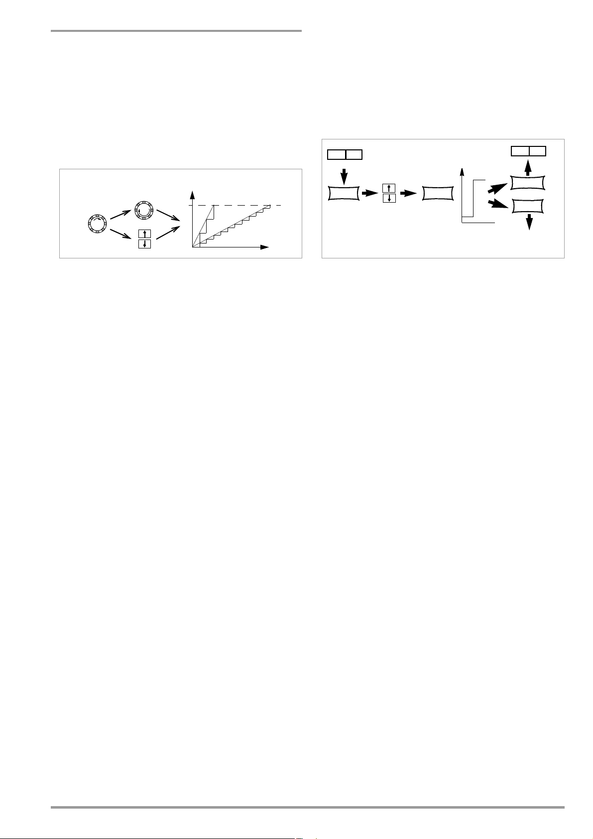
Iset – Output Current
Iset / A
Iout
t
(1)
(2)
(3)
Uset / V
ENTERENTER
ENTER
Uout Iout
Select Uset
Uout Unchanged!
CE/LOCAL
Uout Iout
Iout Unchanged!
Activate
Select Iset
Uset
The procedure for selecting output current Iset is identical to the
procedure for selecting output voltage Uset (4.1.2).
However, the following controls and displays must be substituted:
• Iset rotary knob (chapter 3 [10]
• Right-hand display (chapter 3 [8])
• Yellow Iset/A LED (chapter 3 [9])
• Setting resolution:
4 step widths are possible: 0.001 A / 0.01 A / 0.1 A / 1 A
Attention: Iset may not be set to a value which exceeds Ilim!
! Each time the key is pressed, output voltage is changed
by an amount which corresponds to the value selected
with the resolution setting function.
! Pressing and holding the respective key results in rapid
scrolling, regardless of the step width.
☞ Acknowledge the selected value with the <ENTER> key
[15]. The new value is now activated at the output [4], and
the yellow Uset/V LED [6] is continuously illuminated.
☞ Repeatedly press the <ENTER> key [15] in order to switch
back and forth between Uset and Iset.
4.2.2 Pre-selected Setting (ENTER, scroll keys)
Figure 4.2.2 a Adjusting Uset with a Specified Fixed Value
If the application requires that switching to a new setpoint takes
place in a single jump by pressing a key (without semi-continuous
adjustment), this can be accomplished as follows.
Proceed to the basic setting menu with the <CE/LOCAL> key, i.e.
to the display of momentary output values. Press the <ENTER>
key in order to switch to the pre-selection setting mode. After
switching to this mode, the currently valid setpoint values appear
at both displays (indicated by the LEDs above the display).
As a default function, voltage adjustment is always activated first,
which is indicated by a blinking decimal place at the
corresponding display. Repeatedly press the <ENTER> key in
order to switch back and forth between current adjustment and
voltage adjustment.
The new setpoint can be selected with the scroll keys (and only
with the scroll keys), after selecting voltage or current setpoint
adjustment and the desired resolution. The SET LED blinks in
order to indicate that a change has been made but not yet
activated. The new setpoint is activated after acknowledging with
the <ENTER> key.
Pre-Selecting a Setpoint
☞
Press the <ENTER> key [15].
! The display [5] is switched from Uout (measured voltage value)
to Uset (voltage setpoint). The decimal place which corresponds
to the selected resolution setting blinks.
! The green Uout/V LED goes out, and the yellow Uset/V LED [6]
lights up (as long as the Uset/V LED is continuously illuminated,
direct adjustment with immediate activation of the new value
can be executed with the rotary knob [7]).
Setting resolution:
! 3 step widths are possible: 0.01 V, 0.1 V or 1 V.
☞ Repeatedly press the <SELECT> key [13] until the desired
decimal place (step width) blinks at the display.
Output Voltage:
☞ Press either the <> key or the <> key [11]!
<> (increment) Increases the value
<> (decrement) Decreases the value
! The yellow Uset/V LED[5] starts blinking.
! A blinking Uset/V LED indicates that new values are displayed
but not activated during adjustment. The old Uset value
remains active.
☞ Press the <> key or the <> key [11] until the desired
value appears at the display [5].
GMC-I Messtechnik GmbH 21
• Output voltage jumps from the old value to the new value in a
single step (no intermediate values).
Attention: Uset may not be set to a value which exceeds Ulim!
4.3 Switching the Power Output On and Off
The <OUTPUT> key (chapter 3 [2]) functions independently of the
current operating state of the KONSTANTER.
Details regarding control mode, protective function and status
displays which provide information concerning the output’s
operating mode are included in chapter 3 [3].
Closed Loop Control Mode
The power output can be activated or deactivated by pressing the
<OUTPUT> key [2].
OUTPUT OFF OUTPUT ON
REMOTE status (remote control)
(chapter 3 [12], chapter 4.13)
The <OUTPUT> key [2] is disabled and has no function.
LOCAL LOCKED status (front panel controls disabled)
(chapter 3 [12], chapter 4.13)
The <OUTPUT> key [2] is disabled and has no function.
trG out (T_MODE OUT) and External Trigger Active
The output can be activated an deactivated with the trigger
signal (trG parameter OUT selected).
If the power output has been disabled by applying an external
trigger signal to the analog interface, it cannot be switched on,
neither by means of a command nor with the keys. The
corresponding command is not executed and bit 4 in event
register B is set (output-on error). “Err 25” also appears briefly
at the display as a warning in the event of manual operation.
The status of the power output
by the red LED above the <OUTPUT> key [2]:
LED on = output activated
LED off = output deactivated
In the case of OUTPUT OFF, the control mode displays are also
switched off
(chapter 3 [3]).
If the output has be deactivated as a result of overtemperature
protection, the yellow “240 W” LED [3] in the control mode
display blinks. The output cannot be activated until the
KONSTANTER has returned to its normal operating
temperature.
(chapter 3 [4/22]) is indicated
Page 22

If the Pon RCL function is active, the output is automatically
reactivated after the device has returned to its normal
operating temperature.
Functions which may influence the status of the output
include:
• Manual and computer-aided settings for Iset may not exceed
Ilim.
• Ilim cannot be set to a value which is less than current
setpoint Iset. Iset must be reduced far enough to allow for the
new Ilim setting.
Functions Meaning Manual
Operation
OVP (OVSEt) Overvoltage
protection
OCP Overcurrent
Pon
(POWER_ON)
SEq Sequence chapter 4.7.4 page 70
trG (T_MODE) page 28 page 74
4.4
Limiting the Allowable Working Range: Ulim, Ilim
Allowable setting limits for voltage and current can be restricted in
order to assure ideal matching to the working ranges of the
connected power consumer. The Ulim and Ilim setting functions
are provided to this end. Setting options can be selected with the
respective <SELECT> key. Setting resolution is selected with the
<RESOL> key. The setting itself is entered with the scroll keys.
New settings become immediately active.
Attention!
These settings represent so-called soft limits. This means that
values can be selected both manually and via the computer
interface which lie within these limit values, and that a
corresponding error message is otherwise generated.
Attention!
The actual output quantity is the sum of the digitally selected
setpoint value and the setpoint value specified via the analog
interface. This makes it possible to select values which exceed
the specified soft limit.
protection
page 25 page 69
page 26 page 68
page 26 page 69
Remote
Operation
Settings
See description on page 25.
4.5 Description of OVP and OCP Protection Functions
Protection for the connected power consumer and the
KONSTANTER by means of the following functions:
OVP – overvoltage protection
Functions
• Protection for the connected power consumer
• If voltage at the output terminals exceeds the selected OVP
value, the power output is deactivated.
• Triggering of overvoltage protection causes immediate (< 200
s) deactivation of the output (OUTPUT OFF). The HF power
transmitter is disabled, and the electronic sink for discharging
the output capacitors for approximately 350 ms is activated.
In addition, bit 4 (OVPA) is set in event register A. Bit 4 remains
set in status register A for as long as the trigger value is
exceeded.
•The CV LED blinks as soon as overvoltage protection OVP is
triggered (see also chapter 3 [3]), and the red OUTPUT LED
goes out.
• As soon as the shutdown condition no longer exists, the
power output can be reactivated by pressing the <OUTPUT>
key, by transmitting a trigger signal to the analog interface or by
means of computer control (“OUTPUT ON”
lights up).
Settings
See description on page 25.
➅ red OUTPUT LED
Ulim – Setting the Upper Voltage Limit Value
Functions
• Upper setting limit (soft limit) for Uset
• Prevents inadvertent violation of the maximum voltage value
when adjusting Uset.
• Protection for the connected power consumer
• Ulim has higher priority than Uset.
• Manual and computer-aided settings for Uset may not exceed
Ulim.
• Ulim cannot be set to a value which is less than a previously
selected Uset value. Uset must be reduced far enough to allow
for the new Ulim setting.
Settings
See description on page 25.
Ilim – Setting the Upper Current Limit Value
Functions
• Upper setting limit (soft limit) for Iset
• Prevents inadvertent violation of the maximum current value
when adjusting Iset.
• Protection for the connected power consumer
• Ilim has higher priority than Iset.
OCP – Overcurrent Protection
Functions
• Protects the power consumer from continuous overcurrent.
• Deactivates the power output when load current Iset has been
reached, and the output is switched to the current regulating
mode.
• Current can nevertheless be allowed to exceed Iset for
specified, short periods of time by specifying a delay time (see
below), for example:
! Starting current for electric motors
! In-rush current for capacitive power consumers
! For testing the breaking performance of circuit breakers,
motor protecting switches, fuses etc.
! For determining the short-term load capacity of contacts
and cables, as well as electrical and electronic
components
! In order to maintain short response times when
programming voltage increases
•The CC LED blinks as soon as overvoltage protection OCP is
triggered (see also chapter 3 [3]), and the red OUTPUT LED
goes out.
• The power output can be reactivated at any time by pressing
the <OUTPUT> key, by transmitting a trigger signal to the analog
interface or by means of computer control (OUTPUT ON
OUTPUT LED lights up).
➅ red
Settings
See description on page 26.
22 GMC-I Messtechnik GmbH
Page 23

dLY – Output Off Delay for OCP
Functions
• Delay time prior to deactivation of the power output after
current regulation has been triggered (Iout = Iset)
• Only enabled with activated OCP function (OCP ON)
• If output current Iout drops below Iset before DELAY time
elapses, the shutdown sequence is aborted.
• If current regulation is triggered again, the routine is started
over (at 00.00).
• The default setting after RESET (*RST) is 00.00.
Settings
See description on page 26.
4.7 Operating Menu via the FUNCTION Key
The FUNCTION menu consists of the following functions for
configuring the KONSTANTER’s parameters:
Function group Function Parameter (numeric / text)
■ Setup
SEt Ulim NP: xx.xx
Ilim NP: xx.xx
OVP NP: xxx.x
OCP TP: oFF / on
dLY NP: xx.xx
Pon TP: rSt / SbY / rcL
-
UI
rnd TP: 0 / -1 / -2
TP: oFF / on / rSt
4.6 Display of Momentary Output Values Uout, Iout
and Pout
Uout – Momentary Measured Voltage Value
• Appears at the left-hand display [5].
•The green Uout/V LED [6] lights up and indicates display of the
momentary measured voltage value.
• The measured voltage value is automatically displayed again,
approximately 10 seconds after the last setting has been
made.
• The momentary measured voltage value is displayed
immediately if the user exits the device functions setting mode
by pressing the <CE/LOCAL> key [16].
Iout – Momentary Measured Current Value
• Appears at the right-hand display [8].
• The green Iout/A LED [9] lights up and indicates display of the
momentary measured current value.
• The measured current value is automatically displayed again,
approximately 10 seconds after the last setting has been
made.
• The momentary measured current value is displayed
immediately if the user exits the device functions setting mode
by pressing the <CE/LOCAL> key [16]
Pout – Display Momentary Output Power
Calculated internally based upon momentary measured values
Uout and Iout.
Settings
See description in chapter 4.8.1.
UI_ – Display Measured Values in
Functions
• Reads out stored values for Umin, Umax, Imin and Imax at the
display, or via the computer interface.
• Stored Min-Max values can be read out regardless of the
status selected for the MINMAX function.
Settings
See description in chapter 4.8.1.
U/I Min-Max Memory
■ Analog Interface
AnIF trG TP: oFF / out / rcL / SEq / LLO / UI
SiG1 TP: oFF / on / out / Mode / SEq /
SSEt / U-Lo / U-Hi / I-Lo / I-Hi
SiG2 TP: oFF / on / out / Mode / SEq /
SSEt / U-Lo / U-Hi / I-Lo / I-Hi
■ Sequence Function
SEq* tSEt NP: xx.xx
SSEt NP: oFF / on
tdEF NP: xx.xx
Strt NP: xxx (11... 252)
StoP NP: xxx (12... 253)
rEP NP: xxx (cont. or 1 ... 255)
SEq** TP: Go, Strt, StoP, hold, StEP, cont.
* Sequence function: appears at left-hand display, right-hand display is blank.
** Parameter selection for sequence control: appears at left-hand display, selected parameter
appears at right-hand display.
■ Interface Configuration
buS Addr NP: 0 / 1 / ... / 13 /... / 30 / (UNL)
bAUd NP: 50 / 75 / 150 / 200 / ... / 4800 /
9600 / 19200
dbit NP: 7 / 8
Pbit TP: nonE / ZEro / EVEn / odd / onE
Sbit NP: 1 / 2
■ Adjustment (calibration, chapter 7)
CAL dAtE TP: mm.yylast/new adjustment date
CAL TP: Strt
MEAS UoFF
UoFF NP: x.xxxentry of ext. measured value U
MEAS UFS
UFS NP: xx.xxentry of ext. measured value U
MEAS IoFF
IoFF NP: x.xxxentry of ext. measured value I
MEAS IFS
IFS NP: xx.xxentry of ext. measured value I
CAL End
NP: Numeric Parameters
• Can be selected as a specified value or as a value within an
interval with corresponding resolution.
•Adjust resolution (decimal place) by pressing the <SELECT> key.
• Select with the <> key or the <> key.
• Displayed value = selected value.
-
TP: Text Parameters
• Select parameter with the <> key or the <> key.
• Acknowledge the selected value by pressing the <ENTER> key.
GMC-I Messtechnik GmbH 23
Page 24
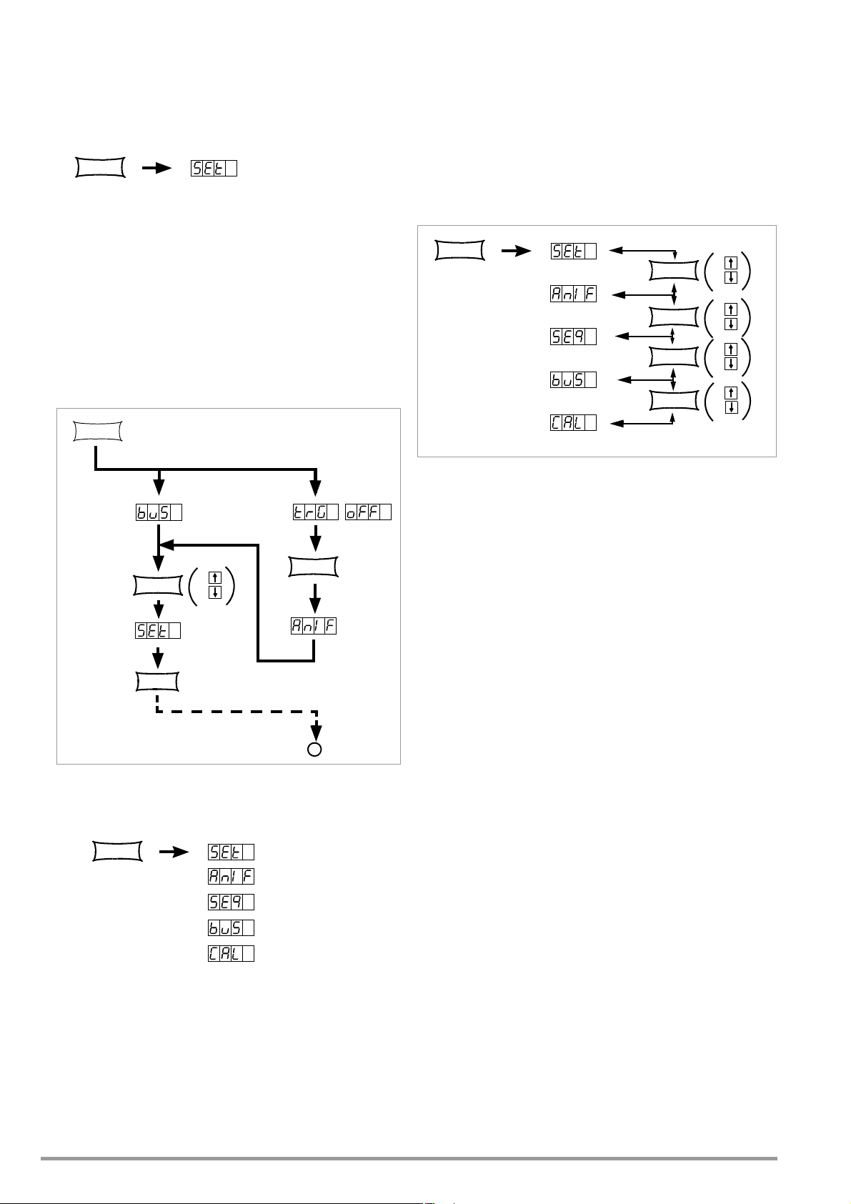
Settings
FUNCTION
FUNCTION
ENTER
FUNCTION
+
Jump to
last edited
function group
Jump to
last edited
function
e.g.
e.g.
e.g.
*
CE/LOCAL
FUNCTION
FUNCTION
FUNCTION
+
FUNCTION
+
FUNCTION
+
FUNCTION
+
☞
Press the <FUNCTION> key [14] at the front of the
KONSTANTER.
If no settings have yet been changed via the FUNCTION menu
after switching the device on, the SEt function group is
accessed upon pressing the <FUNCTION> key.
If settings have already been changed in the function menu,
the last edited function group or function is accessed
automatically.
• Accessing the last edited function:
☞ If you want to configure a function included in the current
function group, select the function group by pressing the
<FUNCTION> key. Detailed information is included in the
respective section of this chapter.
☞ If you want to configure a function from another function
group, first return to the function groups menu by pressing
the <CE/LOCAL> key.
• Forward scrolling through function groups in this menu:
☞ Repeatedly press the <FUNCTION> key or
☞ Press and hold the <FUNCTION> key and repeatedly press
the <> key at the same time.
• Reverse scrolling through function groups in this menu:
☞ Press and hold the <FUNCTION> key and repeatedly press
the <> key at the same time.
• Accessing functions in the selected function group:
☞ Press the <ENTER> key.
Figure 4.7 a Accessing the Functions Submenu
☞ If the function groups menu is currently open, you can
access the following function groups:
Figure 4.7 b Switching Amongst Individual Function Groups
Note
The order in which the commands are explained in the following sections
corresponds to the actual sequence for manual operation of the
SSP KONSTANTER. This should make it easy to configure device functions
and parameters without leafing back and forth through the instructions.
☞ If the desired function group does not appear immediately
at the left-hand display, repeatedly press the <FUNCTION>
key until the name of the desired function group appears
at the left-hand display (SEt in this example).
24 GMC-I Messtechnik GmbH
Page 25
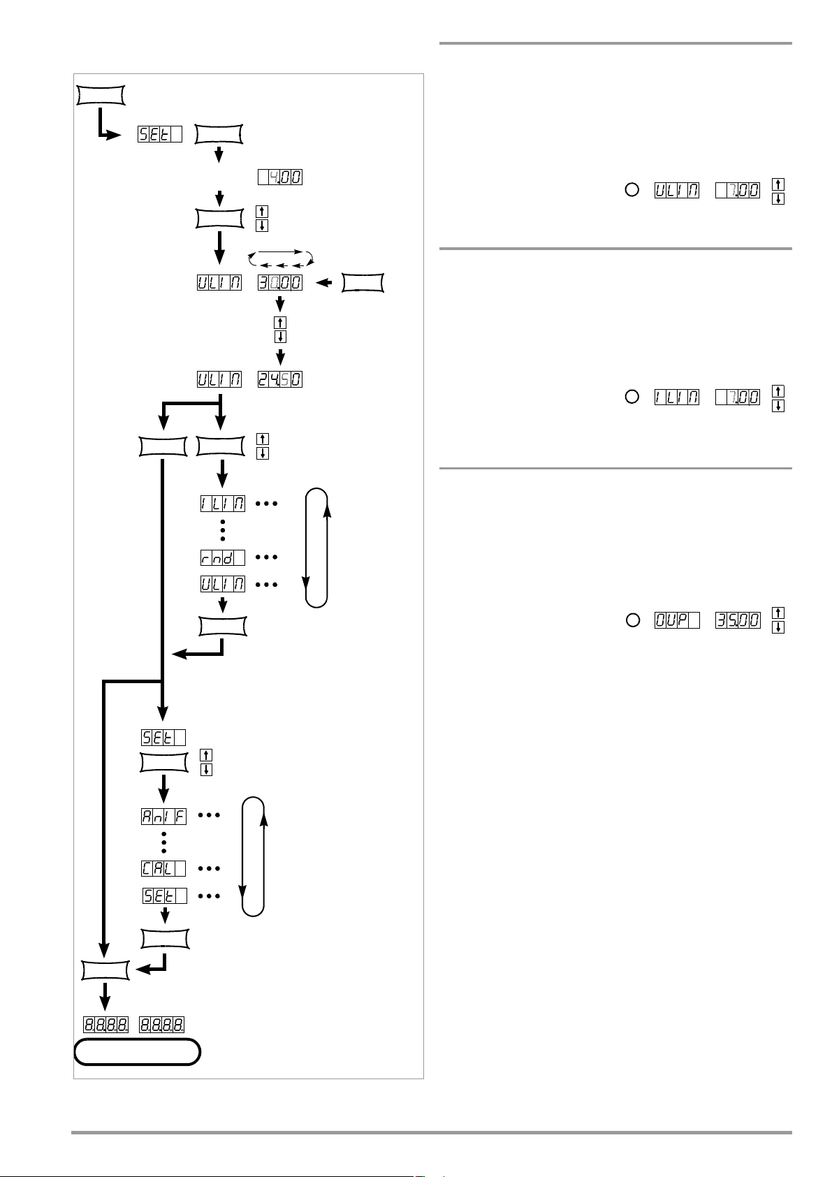
4.7.1 SET – “Setup” Function Group
FUNCTION
+
FUNCTION
+
FUNCTION
+
FUNCTION Press on ce
ENTER
Press repeatedly if necessary
Jump to last
edited setup function
Cursor position
SELECT
Resolution of
numeric parameter
Select a value for
the upper voltage limit
(numeric parameter)
CE/LOCAL
CE/LOCAL
CE/LOCAL
CE/LOCAL
Uout
Iout
*
*
*
Ulim – Upper Voltage Setting Limit
Functions
See functions description on page 22.
Settings
The procedure is described in principle in chapter 4.7.
!
The Ulim display appears in the
window for the setup function,
along with a related numeric
parameter [V].
Ilim – Upper Current Setting Limit
Functions
See functions description on page 22.
Settings
The procedure is described in principle in chapter 4.7.
! The Ilim display appears in
the window for the setup
function, along with a
related numeric parameter
[A].
OVP – Overvoltage Protection Trigger Value
Functions
See functions description on page 22.
Settings
The procedure is described in principle in chapter 4.7.
! The OVP display appears in
the window for the setup
function, along with a
related numeric parameter
[V].
☞ The OVP trigger value should be set at least 1 V higher than the
desired USET output voltage in order to prevent undesired
triggering of the OVP function resulting from overshooting due
to sudden output discharging (minimum values: chapter 1.5.3,
“Electrical Data”)!
☞
The
OVP
trigger value makes reference to the prevailing voltage value
between the output terminals of the SSP. This voltage is increased
USET
by the
parameter during sensing mode operation (remote
sensing) by an amount equal to voltage drop at the output leads. For
OVP
and
USET
this reason, the above defined difference between
must be correspondingly increased during sensing mode operation.
☞ The selected parameter becomes immediately active!
Note
• Overvoltage protection response time is less than 200 μs.
Output voltage generated by the device may exceed OVSET for
the duration of this response time. Maximum overshooting
can be approximately calculated as follows:
Uout = ISET [A] x 200 [μs] / Cout [μF]
ISET = selected current setpoint
Cout = capacitance of the output capacitor
Subsequent discharging time for the output capacitor
Figure 4.7.1 a Path to Ulim Settings
GMC-I Messtechnik GmbH 25
depends upon load, and corresponds to the specified values
for response time at Unom 1 V included in chapter 1.5.3.
• Possible causes for triggering overvoltage protection are listed
in chapter 3 [3], “Control Modes”.
Page 26
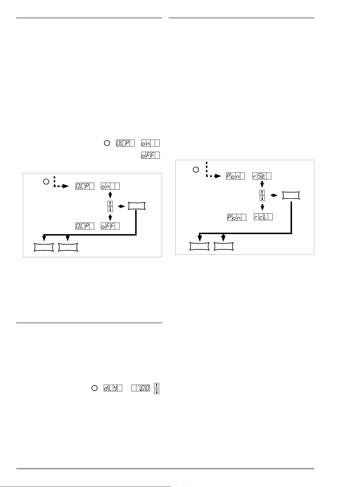
OCP – Overcurrent Protection
*
Select the text parameter
from an options loop
From the SEt function group
ENTER
CE/LOCAL FUNCTION
*
*
Select the text parameter
from an options loop
From the SEt function group
ENTER
CE/LOCAL FUNCTION
*
Pon – Specifying a Power-On Status
Functions
See functions description on page 22.
Setting Parameter
☞
OFF: OCP function is inactive
Continuous current limiting (current regulation)
☞ ON: OCP function activated
The output is deactivated as soon as current limiting has been
active for the specified DELAY time.
☞ The selected text parameter does not become active until the
<ENTER> key is pressed!
Settings
The procedure is described in principle in chapter 4.7.
! The OCP display and a related
text parameter appear in the
setup function window.
Functions
• Use automatic KONSTANTER configuration after power on.
Setting Parameters:
☞
rSt: (RESET) Factory default settings are utilized
☞ SbY: (STANDBY) Same settings as prior to shutdown, power
output remains inactive (OUTPUT OFF)
Disabled panel controls are re-enabled after mains ON.
From firmware version 4.003 onwards:
Disabled panel controls remain blocked even after mains ON.
☞ rcl (RECALL) Same settings as prior to shutdown.
Disabled panel controls remain blocked even after mains ON.
Settings
The procedure is described in principle in chapter 4.7.
! The Pon display and a related text parameter appear in the
setup function window.
Figure 4.7.1 b Path to Selection of the OCP Text Parameter
Note
Load current for the output capacitor is also acquired by the
current regulator, and is limited to a value of Iset Ioad. If the OCP
function has been activated and ISET and DELAY have been set to
low values, the output may even be deactivated if output voltage
is increased. For this reason, DELAY must at first be set somewhat
higher than the resulting output voltage response time.
dLY – Output Off Delay for OCP
Functions
See functions description on page 23.
Settings
The procedure is described in principle in chapter 4.7.
!
The
DELAY
the window for the setup
function, along with a related
numeric parameter [t].
display appears in
Figure 4.7.1 c Path to Selection of the Pon Text Parameter
Note
• The status of the Pon function is not saved as a device setting
to SETUP memory with the <SAVE> key.
• The following settings are recommended, depending upon
how the KONSTANTERs is used:
! Pon rSt: Use in computer controlled systems
! Pon SbY: Common laboratory use
! Pon rcL: Applications which must continue in an
unchanged fashion after power failures.
26 GMC-I Messtechnik GmbH
Page 27
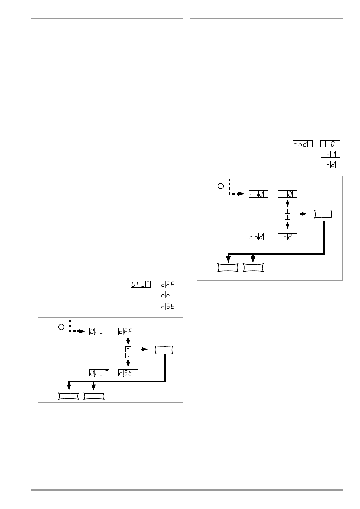
UI_ – U/I Min-Max Measured Value Memory (MINMAX)
Select the text parameter
from an options loop
From the SEt function group
*
ENTER
CE/LOCAL FUNCTION
Select the text parameter
from an options loop
From the SEt function group
*
ENTER
CE/LOCAL FUNCTION
rnd – Rounding Off the Displayed Measured Value
Functions
• Save minimum and maximum measured voltage and current
values.
• Reads out stored values for Umin, Umax, Imin and Imax at the
display, or via the computer interface.
• The MINMAX function can be temporarily set to OFF, for
example before deactivating the output when changing
devices under test. Stored values are then no longer updated,
nor are they automatically reset.
• Stored Min-Max values can be read out regardless of the
status selected for the MINMAX function.
• Stored Min-Max values can always be reset with the UI
_ RST
command.
• Stored Min-Max values can also be reset with the *RST
command, or with the key combination <CE/LOCAL> +
<ENTER> (= RESET).
• The status of the MINMAX function is also saved to SETUP
memory by pressing the SAVE key.
•If the Pon function is set to SbY or rcl, the MINMAX function is
activated upon power-up, but previously measured Min-Max
values are lost when the KONSTANTER is switched off.
•The MINMAX function can also be controlled via the trigger input
at the analog interface.
Setting Parameter
☞
OFF: Storage of Min-Max values is deactivated
☞ ON: Storage of Min-Max values is activated
☞ RST: contents in the Min-Max memory are reset or replaced
with the momentary measured value:
Umin = Uout Umax = Uout
Imin = Iout Imax = Iout
Functions
• Only effective for Uout and Iout measuring function
• Number of decimal places which appear at the display
• Stabilizes the display when fluctuation is expected at the last
decimal place of the measured value
Setting Parameter
☞
0: no rounding
☞ -1: Rounded off one decimal place
☞ -2: Rounded off two decimal places
Settings
The procedure is described in principle in chapter 4.7.
! The rnd display and a related text
parameter appear in the setup function
window.
Settings
The procedure is described in principle in chapter 4.7.
! The UI_ display and a related text
parameter appear in the setup
function window.
☞ Default setting after RESET (*RST): OFF!
Figure 4.7.1 d Path to Selection of the Pon Text Parameter
Figure 4.7.1 e Path to Selection of the rnd Text Parameter
☞ Default setting after RESET (*RST): unchanged
GMC-I Messtechnik GmbH 27
Page 28
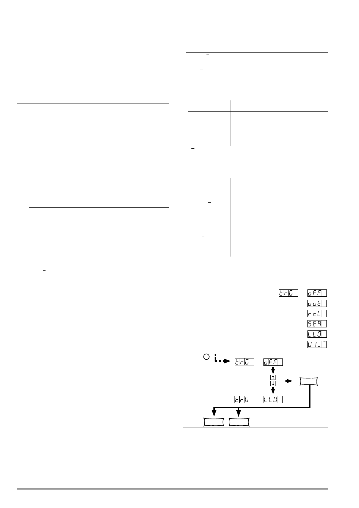
4.7.2 AnIF – “Analog Interface” Function Group
Select the text parameter
from an options loop
From the AniF function group
*
ENTER
CE/LOCAL FUNCTION
The analog interface allows for remote control of the
KONSTANTER.
An isolated digital control input (TRG IN+ / TRG IN-) and digital signal
outputs (SIG1 / SIG2) are available in addition to analog setting
options.
Other devices can be controlled in this way (e.g. counters, alarms,
SSP KONSTANTERs and many more). A master-slave system can
be set up in combination with a second or several
SSP KONSTANTERs (see also chapter 5).
Observe specified maximum current and voltage values for signal
outputs.
SEQUENCE: Sequential execution of specified values for Iset,
Uset and dwell time (see also chapter 4.7.3).
The SEQUENCE function group must be set to SEQUENCE ON
for this function.
TRIGGER Signal Influence on SEQUENCE Status
LOW _
HIGH _ LOW Ends sequence execution by jumping to
HIGH
The SEQUENCE function is started beginning
with the start address,
the stop address.
SEQUENCE GO
☞ LLO: (LOCAL LOCKED) Operation via front panel controls is
disabled.
trG – Function Selection for Trigger Input
Functions
• Floating optocoupler input (TRG IN) at the analog interface
• The trigger input is controlled with a digital signal
(low: 0 V, high: 4 ... 26 V).
• Response time is approximately 1 to 15 ms.
Setting Parameter
☞
OFF: Trigger input function is deactivated, signals at the trigger
input are ignored.
☞ OUT: Trigger input influences the OUTPUT: output on / off
TRIGGER Signal Influence on OUTPUT Status
LOW Status depends upon manual setting or
LOW _
HIGH OUTPUT in the OFF state,
HIGH
HIGH OUTPUT remains OFF or
_ LOW OUTPUT is activated,
programming command
OUTPUT is switched OFF
cannot be switched on – neither manually
nor with a programming command
except in the event of OTP or OVP
☞ RCL: Memory recall from defined start to defined stop address
(step-by-step sequence control)
TRIGGER Signal Influence on step-by-step control
Edge
Low High
Start trigger signal
TRIGGER Signal Influence on Front Panel Controls
LOW All front panel controls are functional.
HIGH All front panel controls are disabled,
except for the mains switch,
no activation with the LOCAL key.
☞ UI_
MIN-MAX function: Storage of Min-Max values for U and I is
controlled by the trigger,
Min-Max function active, (UI _
TRIGGER Signal Influence on Min-Max Status
LOW The Min-Max function is active.
LOW _
HIGH The Min-Max function is inactive.
HIGH
HIGH The Min-Max function is deactivated.
Levels in the in Min-Max memories
remain unchanged.
_ LOW Values in the Min-Max memories are
replaced with momentary output values.
The Min-Max function is activated.
ON)
☞ The status of the trG function is not saved as a device setting
with the SAVE key.
Settings
☞
Procedure for configuring trG ➁ see also
chapter 4.7
! The trG display and a related text
parameter appear in the AnIF function
window.
☞ Default setting after RESET (*RST):
unchanged
HIGH The trigger signal is a high pulse with
a duration of 11 to 800 ms.
A high pulse with a duration > 1.0 s
resets the address counter to the start
address at any point in time, and
execution begins with the next trigger
signal.
Edge
High Low
The high low edge of the (short) trigger
signal results in step-by-step control of
the currently selected sequence,
regardless of the specified time and
number of repetitions.
Recall of the memory’s contents begins
with the START address. Each trigger
signal increasers the address by 1, until
the STOP address is reached. The next
pulse once again causes execution of the
contents of the START address.
Figure 4.7.2 a Path to Selection of the trG Text Parameter
☞ SEQ: Controlling Execution of the SEQUENCE Function
28 GMC-I Messtechnik GmbH
Page 29

SiG1 – Signal Output 1
Select the text parameter
from an options loop
From the AniF function group
*
ENTER
CE/LOCAL FUNCTION
Functions
• Digital open collector output with reference to AGND, max.
switching voltage min. 30 V DC, max. switching current min.
20 mA (e.g. ext. load shedding relay).
Indicates the status of the power output.
• If an event occurs which is associated with the selected
parameter, a corresponding signal is generated at the output.
• Used to link the OUTPUT function via the trigger input in the
case of parallel or series (master-slave) connection of several
SSP KONSTANTERs.
• Control of an external output relay is possible.
• As a status signal for monitoring devices
• As a freely assignable switching output
Setting Parameters SIG1 OUT Status
☞ OFF
Always passive
high
☞ ON
Always active low
☞ OUT
Power output:
OUTPUT ON
OUTPUT OFF
Passive high
Active low
☞ ModE
Control mode signal:
Constant current regulation
Overload (Pmax)
Constant voltage, output Off
Active low
Active low
Passive high
☞ SEq
Status with running sequence
Active low
☞ SSEt
If SSEt is set to ON for special
memory location in the SEQUENCE
otherwise
1
Active low
,
Passive high
☞ U_LO
Umeas < Uset (reference value memory
Umeas Uset254)
Active low
Passive high
☞ U_HI
Umeas > Uset (reference value memory
Umeas Uset255)
Active low
Passive high
☞ I_LO
Imeas < Iset (reference value memory
Imeas Iset254)
Active low
passive high
☞ I_HI
Imeas > Iset (reference value memory
Imeas Iset255)
Active low
Passive high
Setting
☞
Procedure for selecting Sig1: see also
chapter 4.7, “Settings”.
! The Sig1 display and a related text
parameter (status) appear in the
AnIF function window.
Figure 4.7.2 b Path to Selection of the SiG1 Text Parameter
SiG2 – Signal Output 2
Function and Parameters
☞
Identical to SiG1, page 29
Settings
☞
Identical to SiG1, page 29
1
The SSEt parameter must be set to ON for a certain memory location in the SEQUENCE function
group.
☞ When the SEQUENCE is run, an signal is additionally generated
for the read-out of Uset and Iset when this particular memory
location is executed.
☞ The signal is available at the outputs of the analog interface
(SiG1 / SiG2 / SiG1 + SiG2) for the respectively selected dwell
time tSEt or tdEF.
GMC-I Messtechnik GmbH 29
Page 30

4.7.3 SEq – The Sequence Function Group
U/V
12
6
4,5
t/ms
15 2000 20
Tse t
1
Tse t
2
Tse t
3
Range of Memory Locations
111 253 255
SEQUENCE
Occupied Memory Locations
SEQUENCE
SEQUENCE
SEQUENCE
SEQUENCE
SEQ
SEQUENCE
Range of Memory Locations
111 253 255
Occupied Memory Locations
SEQUENCE
SEQ
SEQ
occ. loc. occ. mem. loc. occ. mem. loc.
SEQUENCE
Description
Test sequences can be generated with the SEQUENCE function
group (in accordance with DIN if desired). Setpoints are specified
for voltage (Uset) and for current (Iset), as well as for the
associated time intervals (tset) to this end. In addition, a signal for
external processing can be specified for each test step (Sset).
.
Figure 4.7.3 a Test Signal to Electrical System Simulation during Start-Up
Test sequences can be saved, and changed as required.
The test sequence automatically runs through all specified values
after it has been started, beginning with a specified start address,
and ending with a specified stop address. The number of
sequence repetitions can be selected. The sequence can be
stopped at any time, and then resumed.
The sequence can also be run step-by-step (manual control),
independent of programmed time intervals.
Functions
• Allows for automated, reproducible execution of a series of
USEt, ISEt, tSEt and SSEt values which have been stored to
memory with the <SAVE> function.
Memory Occupancy
• A defined memory location (addresses 11 through 255) is
assigned to each test step which contains specified setpoints
for USEt, ISEt, tSEt and SSEt.
• A SEQUENCE consists of at least one test step.
• The entire range of memory locations for the sequence may
only be occupied by a single sequence.
• Several smaller sequences may also be generated over the
entire range of memory locations.
• New sequences can also be generated consisting of subsegments of occupied memory location ranges by selecting
new start and stop addresses.
Responses to Sequence Start and Stop
•The power output is automatically activated (OUTPUT ON)
when the SEQUENCE function is initialized (automatic
sequence run and step-by-step control).
• The power output can be controlled at all times with the
OUTPUT function during execution of the sequence and
during pauses.
• Stopping the sequence has not effect on the contents of the
sequence memory locations.
• The contents of the memory location with the StoP address
are executed as the last function. The sequence can then be
ended, or can be started over again at the start address,
depending upon the number of repetitions and the contents of
the stop address location.
• If the memory location assigned to the stop address contains
setpoints (i.e. if it is not empty), the output remains active
(OUTPUT ON) using the stop address setpoints after the
sequence has been completed.
• If the memory location assigned to the stop address is empty,
the output is deactivated automatically at this point in time
(OUTPUT OFF).
• The fact that a sequence run is active can be determined by
querying bit 7 SEQB (= SEQuence Busy) in condition register
A (CRA). The end of the sequence is indicated by bit 7 SEQI in
event register A (ERA).
Number of Repetitions and Remaining Repetition Counters
• A sequence can be run 1 to 255 times, or indefinitely until it is
stopped manually (see also page 33).
• If automatic sequence repetitions have been programmed,
(rEP = 1 ... 255 or 0 = continuous), the pointer jumps directly
to the “Strt” memory location after the contents of the “StoP”
memory location have been executed, and the sequences is
continued.
• When the sequence jumps from the stop to the start address
during an automatic sequence run, the remaining repetitions
counter is reduced by 1 (rrep = rrep - 1).
• When the sequence jumps from the stop to the start address
during step-by-step control, the remaining repetitions counter
is not reduced (rrep = rrep).
Response to Empty Memory Locations
• Empty memory locations at the beginning of a sequence are
skipped. The first memory location with valid setpoints is
executed.
• Empty memory locations may be included between the start
and stop addresses, but these are skipped.
• Empty stop address:
– rrep > 1: If a remaining number of repetitions has yet to be
run, the empty memory location assigned to the stop address
is skipped. The memory location assigned to the start
address is then executed.
– rrep = 1: After the last repetition has been run, the empty
memory location assigned to the stopped address results in
an OUTPUT OFF status.
30 GMC-I Messtechnik GmbH
Figure 4.7.3 b Range of Memory Locations and Sequences
Page 31

tSEt – Memory Location-Specific Dwell Time
Select the text parameter
from an options loop
ENTER
CE/LOCAL FUNCTION
SELECT
Cursor position
Resolution of
numeric parameter
*
From the SEq function group
Select the text parameter
from an options loop
From the SEq function group
*
ENTER
CE/LOCAL FUNCTION
SSEt – Setting a Digital Switching Function
Functions
Special dwell time (see also Figure 4.7.3 a):
• For the voltage-current value pair at a specific memory
location within a SEQUENCE
• For all status signals generated for these memory locations
Setting Range
00.00 s The tdEF value is used.
00.01 s to 99.99 s Maximum resolution: 0.01 s
99.99 s Assignment of the specified time to
several consecutive SEQUENCE
memory locations with identical voltage
and current values.
Values include rise time and decay time (see also Figure 4.7.3 a).
Edge times are only assure within a limited load impedance range
(see also Technical Data).
Settings (see sequence settings and execution on page 35)
☞ Procedure for selecting tSEt, (see also chapter 4.7):
! The tSEt display appears in the window for the SEq function,
along with a related numeric parameter [s].
Functions
• Preparation of the SSP KONSTANTER for the read-out of a
status signal from a specific memory location.
• The duration of the signal depends upon the dwell time, tSEt
or tdEF, selected for the memory location.
• The signal is read out to the analog interface’s SiG1 and/or SiG2
outputs.
• Prerequisite: The desired output (SiG1, SiG2 or SiG1 and SiG2)
must be prepared with the SSEt parameter in the AniF function
menu (see also page 29).
Setting Parameter
☞
OFF: No status signal
☞ ON: Signal outputs prepared for read-out of a status signal
Settings (see sequence settings and execution on page 35)
☞ Procedure for selecting SSEt, (see also chapter 4.7 “Settings”):
! The SSet display and a related text parameter appear in the
SEq function window.
Figure 4.7.3 c Path to tSEt Settings
☞ Set resolution, i.e. the decimal place (cursor position) of the
numeric parameter, by repeatedly pressing the <SELECT> key.
☞ Enter dwell time based on the previously entered resolution
value using the <> key or the <> key.
☞ After selecting the value, jump to the next or the previous
sequence function by pressing the <FUNCTION> key, or by
simultaneously pressing the <FUNCTION> key and the <> key
or the <> key.
☞ The last selected and displayed value for the numeric dwell
time parameter is used as a default setting.
Figure 4.7.3 d Path to Selection of the SSEt Text Parameter
☞ Select the desired parameter with the <> key or the <> key.
☞ Acknowledge your selection with the <ENTER> key.
! Parameters can be scrolled through in a loop with the <> key
or the > key.
☞ Advance through the SEq functions menu by pressing the
<FUNCTION> key or the <FUNCTION><> and <> keys, or
press the <CE/LOCA L> key to jump back to the function group
menu (FUNCTION).
GMC-I Messtechnik GmbH 31
Page 32

tdEF – Dwell Time Independent of Memory Location
Select the text parameter
from an options loop
From the SEq function group
*
ENTER
CE/LOCAL FUNCTION
SELECT
Cursor position
Resolution of
numeric parameter
Possible selections for the
memory location start address
From the SEq function group
Select the
start address
FUNCTION
+
Strt – Sequence Start Address
Functions
• Default dwell time:
– For all voltage-current value pairs included in a sequence to
whose memory locations no special dwell time has been assigned
(tSEt = 00.00)
– For all status signals generated for these memory locations
• tdEF is used primarily to speed up programming if the value for
a certain dwell time is used repeatedly within a given
SEQUENCE.
Setting Range
0.01 s to 99.99 s, maximum resolution: 0.01 s
Settings (see sequence settings and execution on page 35)
☞ Do not enter tdEF until all Uset, Iset and tset values have been
assigned to all necessary memory locations!
☞ Procedure for selecting tdEF (see also chapter 4.7, “Settings”):
! The tdEF display appears in the window for the SEq function,
along with a related numeric parameter [s].
Functions
• The beginning of a range within which memory locations or
content will be deleted or added
•The SEQUENCE is always defined by means of a start address and a
stop address.
• The address of the memory location from which the SEQUENCE
will start
• The start address can correspond to any memory location from 11
to 255.
•The start address is selected immediately before initially starting
a new SEQUENCE.
•The last selected start address is always valid for any given
sequence, regardless of the point in time at which the sequence
is started.
• The start address for a sequence change can be selected
independent of the stop address.
! The contents of the memory location with the Strt address are
executed as the first function.
Setting Parameter
11 Lowest possible memory location Strt address
255 Highest possible memory location Strt address
Figure 4.7.3 e Path to tdEF Settings
☞ Set resolution, i.e. the decimal place (cursor position) of the
numeric parameter by repeatedly pressing the <SELECT> key.
☞ Enter dwell time based on the previously entered resolution
value using the <> key or the <> key.
☞ After selecting the value, jump to the next or the previous
sequence function by pressing the <FUNCTION> key, or by
simultaneously pressing the <FUNCTION> key and the <> key
or the <> key.
! The last selected and displayed value for the numeric dwell
time parameter is used as a default setting.
Settings (see sequence settings and execution on page 35)
☞ Procedure for selecting Strt, (see also chapter 4.7 “Settings”):
! The Strt display appears in the window for the SEq function,
along with a related numeric parameter.
Figure 4.7.3 f Path to Start Address Selection
☞ Select the desired memory location with the <> or the <>
key.
☞ After selecting the value, jump to the next or the previous
sequence function by pressing the <FUNCTION> key, or by
simultaneously pressing the <FUNCTION> key and the <> key
or the <> key.
! The last selected and displayed value for the Strt address is
used as a default setting.
32 GMC-I Messtechnik GmbH
Page 33

StoP – Sequence Stop Address
Possible selections for the
memory location stop address
From the SEq function group
Select the
stop address
FUNCTION
+
From the SEq function group
Select a value for
number of repetitions
FUNCTION
+
rEP – Sequence Repetitions
Functions
• The end of a range within which memory locations or content
will be deleted or added
•
The
SEQUENCE
is always
defined by means of a start address and a stop
address.
• Memory location at which a SEQUENCE will be ended
• The stop address can correspond to any memory location from 11
to 255.
•The stop address is selected immediately before initially starting a
new SEQUENCE.
•The last selected stop address is always valid for any given
sequence, regardless of the point in time at which the sequence
is started.
• The stop address for a sequence change can be selected
independent of the stop address.
! The contents of the memory location with the stop address are
executed as the last function (reP
Setting Parameter
11 Lowest possible memory location stop address
255 Highest possible memory location stop address
Functions
• Defines the number of SEQUENCE repetitions from the start
address to the stop address.
•The SEQUENCE is run from the selected start address to the
stop address. If repetitions have been programmed, the
pointer automatically jumps from the stop address back to the
start address, and the sequence is started over again.
•The rEP value is stored to the setup memory as a device
setting with the SAVE key.
Setting Parameter
cont Continuous repetition until the sequence is stopped
manually (page 36 ff,) or by means of computer
control (page 70)
1 ... 255 Number of possible repetitions
Settings (see sequence settings and execution on page 35)
☞ Procedure for selecting rEP, (see also chapter 4.7):
! The rEP display appears in the window for the SEq function,
along with a related numeric parameter [s].
Settings (see sequence settings and execution on page 35)
☞ Procedure for selecting StoP, see also chapter 4.7:
! The StoP display appears in the window for the SEq function,
along with a related numeric parameter.
Figure 4.7.3 g Path to Stop Address Selection
☞
Select the memory location with the <> key or the <> key.
☞ After selecting the value, jump to the next or the previous
sequence function by pressing the <FUNCTION> key, or by
simultaneously pressing the <FUNCTION> key and the <> key
or the <> key.
! The last selected and displayed value for the numeric stop
address parameter is used as a default setting.
Figure 4.7.3 h Path to rEP Setting
☞ Select the desired number of repetitions with the <> or the
<> key.
☞ After selecting the value, jump to the next or the previous
sequence function by pressing the <FUNCTION> key, or by
simultaneously pressing the <FUNCTION> key and the <> key
or the <> key.
! The last selected and displayed value for the numeric
parameter (number of repetitions) is used as a default setting.
GMC-I Messtechnik GmbH 33
Page 34

SEq – Sequence, Automatic Memory Recall
Select the text parameter
from an options loop
From the SEq function group
*
ENTER
CE/LOCAL FUNCTION
Continue in the SEq function group
ENTER
FUNCTION
+
Jump to the start address or the
first address with valid contents
Step-by-step control
LOCKED/SEQ
LOCKED/SEQ
Continue in the SEq function group
ENTER
FUNCTION
+
Sequence running
LOCKED/SEQ
LOCKED/SEQ
Select the
from an options loop
From the SEq function group
*
ENTER
CE/LOCAL
FUNCTION
ENTER
ENTER
text parameter
Functions
• Controls automatic and step-by-step sequence runs.
Setting Parameter
☞
Strt: select step-by-step control , jump to start address (status:
RDY HOLD), execute command with the <ENTER> key.
☞ GO: select SEQUENCE, jump to start address and start (status:
RDY RUN), execute command with the <ENTER> key.
Additional Setting Parameters
with running or suspended sequence, and in step-by-step mode
☞
hold: SEQUENCE runs stops at current address (status: RUN
HOLD), execute command with the <ENTER> key.
☞ cont: SEQUENCE is resumed at next address (status: HOLD
RUN), execute command with the <ENTER> key.
☞ StEP: execute next memory location and start (status: HOLD
HOLD), execute command with the <ENTER> key.
☞ StoP: SEQUENCE is stopped and jumps to stop address (status:
RUN RDY or HOLD RDY), execute command with the
<ENTER> key.
! The first valid memory location is now executed, and the
values saved to this location (Uset, Iset and SSEt) are read out
to the power output and the signal output.
The LOCKED/SEQ LED blinks slowly .
Figure 4.7.3 k Preparing for Automatic SEQUENCE Control
! In this case, all memory locations are executed, one after the
other, from the start address to the stop address, and the
respective values saved to each location (Uset, Iset, tdef/tset
and SSEt) are read out to the power output and the signal
output.
The LOCKED/SEQ LED blinks rapidly. .
Settings (see sequence settings and execution on page 35)
☞ Procedure for selecting SEq, (see also chapter 4.7):
! The SEq display appears in the window for the SEq function.
☞ Press the <ENTER> key in order to switch to the SEQUENCE
menu.
☞ Repeatedly press the <FUNCTION> key (max. 6 times) until the
SEq Go function appears.
Figure 4.7.3 i Preparing a SEQUENCE
☞ Acknowledge the sequence with the <ENTER> key.
Note
Automatic and step-by-step sequence control (external trigger
!
or setting command) are not interlocked.
! After the SEQUENCE run has been started, various error
messages may appear for a period of approximately 1 second
(see also page 36 and the appendix).
! If an error occurs during execution of the sequence, bit 5 SEQE
(SEQuence Error) is set in event register B (ERB).
☞ The procedure shown in Figure 4.7.3 l must be used for
setting up and starting sequences for SSP KONSTANTERs with
software version < REL. 003.
In this case, sequences can only be set up and started if the
SEQ ON test parameter has been selected after entering the
SEq menu.
Figure 4.7.3 j Preparing for Step-by-Step Control
34 GMC-I Messtechnik GmbH
Figure 4.7.3 l SEQUENCE preparation with software
version < REL. 003
Page 35

ENTER
ENTER
SAVE
The start address must be entered,
and the ENTER key then increases
FUNCTION
FUNCTION
FUNCTION
FUNCTION
FUNCTION
FUNCTION
ENTER
+
FUNCTION
Function
Groups Menu
Functions
Menu
CE/LOCAL
FUNCTION
Repeatedly press the FUNCTION key
until SEq appears at the left-hand
or
or
Uset
Iset
FUNCTION
FUNCTION
FUNCTION
+
the address by 1 automatically.
FUNCTION
+
FUNCTION
+
FUNCTION
+
FUNCTION
+
FUNCTION
11
1
2
3
4
5
6
7
8
9
10
12
13
14
15
16
17
18
19
20
21
13a
Display Blinks
ENTER
22
display
Setting all Required Values for a Sequence
Read the detailed explanations included in chapter 4.6 and 4.7.3 first.
1 Press the <FUNCTION>. key.
2The function groups or functions menu appears.
3 If the functions menu is not displayed, press the <CE/LOCAL>
key in order to return to the function groups menu.
4 If the functions menu is displayed, repeatedly press the
<FUNCTION> key until SEq appears at the left-hand display (the
right-hand display remains blank).
5 Press the <ENTER> key to access the sequence functions
menu. tSEt appears at the left-hand display.
6Adjust Uset and Iset with the rotary knob and/or the <> and
<> keys if necessary.
[Uset and Iset value can be adjusted at any time, and assigned to a
memory location by pressing the <SAVE> and <ENTER> keys.]
The display can be returned immediately to the previously edited function (in
this case tSEt)
7 Select a tSEt value with the <> or the <> key if necessary,
and continue by pressing the <FUNCTION> key.
8Set SSEt to on or oFF with the <> key or the <> key.
9
Press the <
10 Select the desired memory locations (between 11 and 255)
with the <> key or the <> key.
11 Press the <ENTER
location and the
12 Enter the next setting for Uset, Iset, tset and SSEt , and
continue until all values have been entered for the entire
sequence.Use rotary knobs only for Uset and Iset settings.
Press the <FUNCTION> and <> keys for tset settings.
Press the <FUNCTION> key only for SSEt settings.
13 After saving the last step of the sequence loop (13a) with the
<SAVE> and <ENTER> keys, press the <FUNCTION> key in
order to continue to the tdEF setting.
14 Enter a tdEF value if necessary, acknowledge by pressing the
<FUNCTION> key and/or jump to the next function.
15 Strt - Entry of a sequence start address is prompted.
16 Select a start address with the <> key or the <> key if
necessary, acknowledge by pressing the <FUNCTION> key
and/or jump to the next function.
17 StoP - Entry of a sequence stop address is prompted.
18 Select a stop address with the <> key or the <> key if
necessary, acknowledge by pressing the <FUNCTION> key
and/or jump to the next function.
19 rEP - Entry of the number of sequence repetitions is prompted.
20 Select the desired number of repetitions with the <> key or
the <> key if necessary, acknowledge by pressing the
<FUNCTION> key and/or jump to the next function.
21 SEq Go blinks at the display, indicating that the sequence can
now be started.
22 Press the <ENTER> key. The sequence is run using the
selected values.
by pressing the <FUNCTION> key.
SAVE
> key. The memory location (
memory address is automatically increased by 1.
Sto
) is displayed.
> key. The setting is stored to the memory
Jump from the Uset / Iset settings to the last edited function, or from a
given function to the next function by pressing the <FUNCTION> key.
Press the <FUNCTION> key and the <> key to jump back to the
previous function.
The LOCKED/SEQ LED blinks to indicate that a sequence is running.
The example included here is only intended to demonstrate reliable
sequence programming. You can use other procedures as well, which
may be easier or faster for you.
GMC-I Messtechnik GmbH 35
Figure 4.7.3 m Setting all Required Values for a SEQUENCE
Page 36

Checking the Sequence
Functions
The following parameters can be checked at the display menu
!
while the sequence is running, or when it has been suspended:
> Pout = max. output power
> U_
> U
> I_ = min. output current
> I = max. output current
> rcl = address of the current memory location
> rrEP = number of repetitions yet to be executed
> USEt = momentary output voltage
> ISEt = momentary output current
> tSEt = execution time for the current address
> SSEt = output level for SSEt switching function
= min. output voltage
= max. output voltage
(tSEt or tdEF), no display of remaining time
Checking the Sequence with Manual Operation
☞
Press the <SELECT> key and browse through the display
menu.
☞ Further information is included in chapter 4.8.
Checking the Sequence with Remote Querying
The status of the sequence can be queried by means of remote
command (see page 70).
Possible responses to text: “RUN”, “HOLD”, “RDY”
RUN: active sequence
HOLD: sequence suspended
RDY: device in initial state
Numeric value for number of repetitions yet to be executed (rrep)
Numeric value for current memory address (rcl)
Influencing Step-by-Step Control
Step-by-step control is used to test Uset, Iset and Sset setpoint
values in a time-independent fashion before a sequence is run
automatically. Step-by-step control is activated by executing the
sequence START command, or by initial execution of the sequence
STEP command.
Execute Next Address (status: HOLD HOLD)
Functions
! The next or the previous memory location can be selected at
any time from a suspended sequence – in the step-by-step
control mode. The setpoints saved to the next or the previous
memory location are executed. The selected dwell time of the
exited and the new memory address is not taken into
consideration.
• The output retains its switching status (output On or Off).
• When jumping from the stop address to the start address or
back again, the remaining repetitions counter (rrep) remains
unchanged.
Procedure:
☞ With suspended sequence,
– press the <ENTER> key (next address) or
– the <> key (next address)
the <> key (previous address) or
– press the <FUNCTION> key and then browse with the
<> key, the <> or the <FUNCTION> key
until SEq step appears
and execute the command (next address) with the
<ENTER>
key.
! The sequence executes the next or the previous address.
! If the sequence is in the HOLD status, the selected dwell time
is irrelevant.
! The LOCKED/SEQ LED blinks slowly in the HOLD status.
• Start automatic sequence run from the current memory
location: see resuming the sequence from the HOLD status in
the following chapter.
• Start automatic sequence run: see sequence restart in the
following chapter.
Jump to the stop address: see ending the sequence at the stop
•
address
End step-by-step control at the current address: see ending the
•
sequence at the current address in the following chapter.
in the following chapter.
Influencing the Automatic Sequence Run
Stop Sequence Manually – End at Stop Address
(status: RUN RDY)
Executing the Start Address and Beginning Step-by-Step Control
(status: HOLD HOLD, or RUN HOLD)
Functions
! The start address can be selected at any time
suspended or a running
address are executed. The selected dwell time of the exited and the
new memory address is not taken into consideration.
sequence
. The setpoints saved to the start
from a
! The device is switched from automatic sequence to step-by-
step control the first time this step is executed.
• The output is switched to the output on status.
Procedure:
☞ With interrupted or running sequence,
– press the <FUNCTION> key and then browse with the
<> key, the <> or the <FUNCTION> key
until SEq start appears,
and execute the command with the <ENTER> key.
! The SEQUENCE executes the start address.
! If the sequence is in the HOLD status, the selected dwell time
is irrelevant.
! The LOCKED/SEQ LED blinks slowly in the HOLD status.
Functions
A SEQUENCE can be stopped (ready status) at any time while it
!
is running (run status), or when it has been suspended (hold
status).
! The sequence jumps to the stop address when interrupted.
• If the memory location assigned to the stop address is empty,
the Uset, Iset and Sset values from the last executed address
are retained. If the memory location assigned to the stop
address is not empty, Uset and Iset are changed to the
corresponding values. Selected dwell time Tset of the of the
last executed memory location is not taken into consideration.
! The output retains its switching status (output On or Off) if the
memory location assigned to the stop address is not empty.
The output is switched to the off status if the memory location
assigned to the stop address is empty.
Procedure:
☞
Press the <FUNCTION> key.
! SEq StoP blinks at the display.
☞ Press the <ENTER> key.
! The contents of the stop address are executed. The sequence
is ended.
36 GMC-I Messtechnik GmbH
Page 37

Stop Sequence at Current Address
(status: RUN
HOLD)
End the Sequence at the Stop Address (status: HOLD RDY)
Functions
! A running SEQUENCE can be suspended for an indefinite period
of time.
• Uset, Iset and Sset retain the values specified in the current
memory location. Selected dwell time Tset of the current
memory location is not taken into consideration.
• The output retains its switching status (output On or Off).
•The SEQUENCE can be resumed (cont) at the next memory
location, or ended at the current address <CE/LOCAL> or the stop
address (stop), or restarted (go).
In addition, step-by-step control can be started at the next
address (Step) or at the start address (Start) as well.
Procedure:
☞ With running SEQUENCE,
– press the <ENTER> key
or
– press the <FUNCTION> key and then browse with the
<> key, the <> or the <FUNCTION> key
until SEq hold appears
and execute the command with the <ENTER> key.
! The command is executed when the key is released.
! The SEQUENCE stops at the current address.
! The LOCKED/SEQ LED blinks slowly in the HOLD status.
Functions
! A suspended SEQUENCE can be ended at any time by
executing the stop address.
• If the memory location assigned to the stop address is empty,
the Uset, Iset and Sset values from the hold address are
retained. If the memory location assigned to the stop address
is not empty, Uset and Iset are changed to the corresponding
values. Selected dwell time Tset of the of the current memory
location is not taken into consideration.
• The output status is determined by the content of the stop
address. The output retains its switching status (output On or
Off) if the memory location assigned to the stop address is not
empty. The output is switched to the off status if the memory
location assigned to the stop address is empty.
Procedure:
☞ With suspended SEQUENCE,
– press the <FUNCTION> key and then browse with the
<> key, the <> or the <FUNCTION> key
until SEq stop appears
and execute the command with the <ENTER> key.
! The SEQUENCE is ended and the output status is determined
by the content of the stop address.
! The LOCKED/SEQ LED does not blink in the RDY status.
End the Sequence at the Current Address (status: HOLD RDY)
Resuming the Sequence from the HOLD Status
(status: HOLD RUN)
Functions
! A suspended SEQUENCE can be resumed at any time.
• The output retains its switching status (output On or Off).
The selected dwell time of the of the exited memory location is
not taken into consideration.
! The sequence is now resumed starting with the next address,
and the values stored to the respective memory location (Uset,
Iset, tdef/tset and SSEt) are read out to the power and signal
outputs.
! In the case of very long dwell times, you can advance
prematurely to the next memory location by pressing the
<ENTER> key twice (status: RUN HOLD RUN).
Procedure:
☞ With suspended SEQUENCE,
– press the <ENTER> key
or
– press the <FUNCTION> key and then browse with the
<> key, the <> or the <FUNCTION> key
until SEq cont appears
and execute the command with the <ENTER> key.
! The command is executed when the key is released.
! The SEQUENCE is resumed starting with the next memory
location.
! The LOCKED/SEQ LED blinks rapidly in the run status.
Functions
! A suspended SEQUENCE can be ended at the current address
at any time.
• Uset, Iset and Sset retain the values specified in the current
memory location. Selected dwell time Tset of the of the
current memory location is not taken into consideration.
• The output retains its switching status (output On or Off).
Procedure:
☞ With suspended SEQUENCE,
– press the <CE/LOCAL> key.
! The SEQUENCE is ended and the output status is determined
by the content of the current address.
! The LOCKED/SEQ LED does not blink in the RDY status.
Restarting the SEQUENCE (status: HOLD RUN or RUN RUN)
Functions
! A suspended or running SEQUENCE can be restarted at any
time.
• The output is switched to the output on status.
! In this case, all memory locations are executed, one after the
other, from the start address to the stop address, and the
respective values saved to each location (Uset, Iset, tdef/tset
and SSEt) are read out to the power and signal outputs.
Procedure:
☞ With interrupted or running SEQUENCE,
– press the <FUNCTION> key and then browse with the
<> key, the <> or the <FUNCTION> key
until SEq go appears
and execute the command with the <ENTER> key.
! The SEQUENCE is restarted.
GMC-I Messtechnik GmbH 37
Page 38

ENTER
ENTER
ENTER
SEQUENCE
SEQUENCE
Sequence is resumed
Resume sequence
Restart sequence
End sequence
Select:
The setting
is executed
in hold status
LOCKED/SEQ
LOCKED/SEQ
in run status
LOCKED/SEQ
Step-by-step, start address
Step-by-step, next address
FUNCTION
FUNCTION
CE/LOCAL
End at
current address
Executing the Start Address and Beginning Step-by-Step Control
(status: HOLD HOLD or RUN HOLD)
Functions
! The start address can be selected at any time from a
suspended or a running SEQUENCE. The setpoints saved to the
start address are executed. The selected dwell time of the
exited and the new memory address is not taken into
consideration.
! The device is switched from automatic sequence to step-by-
step control the first time this step is executed (see page 36).
• The output is switched to the output on status.
• The remaining repetitions counter is reset to the initial value
(rrep = rep).
Procedure:
?
☞
With interrupted or running SEQUENCE,
– press the <FUNCTION> key and then browse with the
<> key, the <> or the <FUNCTION> key
until SEq start appears
and execute the command with the <ENTER> key.
! The SEQUENCE executes the start address.
! The selected dwell time of the new and the exited memory
address is not taken into consideration.
! The LOCKED/SEQ LED blinks slowly in the HOLD status.
Figure 4.7.3 n Suspending and Resuming a Sequence
Executing the Next Address and Beginning Step-by-Step Control
(status: HOLD HOLD)
Functions
! The next memory location can be selected at any time from a
suspended SEQUENCE. The setpoints saved to the next
memory location are executed. The selected dwell time of the
exited and the new memory address is not taken into
consideration.
! The device is switched from automatic sequence to step-by-
step control the first time this step is executed (see page 36).
• The output retains its switching status (output On or Off).
• When jumping from the start address to the stop address, the
remaining repetitions counter (rrep) remains unchanged.
Procedure:
☞ With suspended SEQUENCE,
– press the <FUNCTION> key and then browse with the
<> key, the <> or the <FUNCTION> key
until SEq step appears
and execute the command with the <ENTER> key.
! The SEQUENCE executes the next address.
! The selected dwell time of the new and the exited memory
address is not taken into consideration.
! The LOCKED/SEQ LED blinks slowly in the HOLD status.
Adding New Settings to an Existing SEQUENCE
See chapter 4.9.4, page 43.
Deleting an Individual SEQUENCE Memory Location
See chapter 4.9.5, page 44.
4.7.4 buS – The “Interface” Function Group
The KONSTANTER can be set up for data transmission to a
computer in the interface configuration function group. In this
case, all of the settings previously selected with DIP switches are
entered via menu functions.
The serial port (RS 232) or the (optional) parallel port (IEEE 488) is
used for communication.
Addr – Setting the Device Address
• An address must be assigned to the SSP KONSTANTER in
order to assure that it functions correctly together with other
devices on the IEC bus.
If the KONSTANTER receives its own address from the computer, it
•
interprets subsequent data and executes the respective commands.
• If it receives the address of another device, all subsequent
data are ignored until it receives its own address.
Settings
☞
Procedure for selecting Addr, and setting the desired parameter
(see chapter 4.7):
☞ Press the <FUNCTION> key in order to access the FUNCTION
menu.
! The last edited function or function group is accessed
automatically.
☞ Select buS configuration if necessary by pressing the
<FUNCTION> key, or the <FUNCTION> key and simultaneously
the <> key or the <> key.
! buS appears at the left-hand display.
☞ Acknowledge by pressing the <ENTER> key.
38 GMC-I Messtechnik GmbH
Page 39
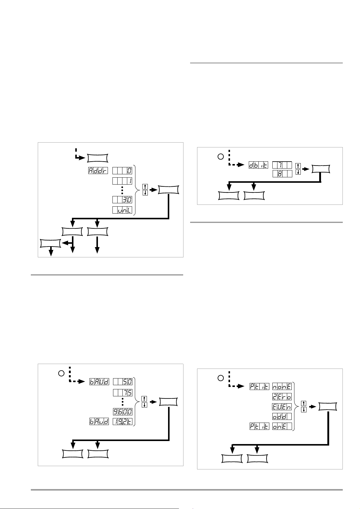
! The buS functions menu appears.
From the buS function group
Select the
device address
FUNCTION
Press repeatedly if necessary
CE/LOCAL FUNCTION
ENTER
CE/LOCAL
Select the text parameter
from an options loop
From the buS function group
*
ENTER
CE/LOCAL FUNCTION
From the buS function group
*
ENTER
CE/LOCAL FUNCTION
Select the text parameter
from an options loop
From the buS function group
*
ENTER
CE/LOCAL FUNCTION
☞ Select the Addr function by pressing the <FUNCTION> key, or
the <FUNCTION> and simultaneously the <> key or the <>
key.
! Addr appears at the left-hand display, and the last selected
parameter appears at the right-hand display.
☞ Select an address for the SSP KONSTANTER with the <> or
the <> key.
!
Any address within a range of 0 to 31 may be selected.
! The selected address must be the same as the address
selected for the SSP KONSTANTER at the computer.
! Address 0 is usually assigned to the controller.
! Address 31 means unL (unlist).
☞ Acknowledge your selection with the <ENTER> key.
! The display is returned to the functions menu after
acknowledging with the <ENTER> key.
Settings
☞
Procedure for selecting bAud and setting the desired parameter
(see chapter 4.7):
! bAud appears in the buS display along with the related
parameter (transmission speed).
dbit – Selecting the Number of Data Bits
• Either 7 or 8 data bits can be used.
• Settings at the SSP KONSTANTER and the controller must be
identical.
Settings
☞
Procedure for selecting dbIt and setting the desired parameter
(see chapter 4.7):
! dbIt appears in the buS display along with the related
parameter (number of data bits).
Figure 4.7.4 a Path to Device Address Selection
bAud – Setting Transmission Speed
• Specifies transmission speed in bits per second.
• The baud rate is an operating parameter of the serial interface.
• A low baud rate should be used in the case of large distances
between communicating devices and in EMC-critical
environments.
• Settings at the SSP KONSTANTER and the controller must be
identical.
• The baud rate can be set to one of the following values:
50, 75, 150, 200, 300, 600, 1200, 1800, 2400, 3600, 4800,
7200, 9600 or 19,200 bits per second.
Figure 4.7.4 c Path to Selection of the dbIt Text Parameter
Pbit – Setting the Parity Bit
• Parity or check bits are used to detect transmission errors.
• They are added to the character string so that the sum of H or
L is even or odd as defined.
• The parity bit can be set to one of the following values:
none No parity bit
ZEro Always 0
EVEn Even numbered
odd Odd numbered
nonE Always 1
! A parity bit should always be used in EMC-critical
environments.
! Settings at the SSP KONSTANTER and the controller must be
identical.
Settings
☞
Procedure for selecting Pbit (see also chapter 4.7):
! Pbit appears in the buS display along with the related
parameter (parity bit).
Figure 4.7.4 b Path to Selection of the bAud Text Parameter
GMC-I Messtechnik GmbH 39
Figure 4.7.4 d Path to Selection of the PbIt Text Parameter
Page 40

SbIt – Selecting the Number of Stop Bits
From the buS function group
*
ENTER
CE/LOCAL FUNCTION
CE/LOCAL
Uout
Iout
FUNCTION
SELECT
SELECT
SELECT
SELECT
SELECT
SAVE
RCL
Uout/IoutUset/Iset
FUNCTION
MENU
SAVE
MENU
RCL
MENU
Abort
Abort
Abort
Abort
Abort
• Either 1 or 2 stop bits can be used.
! Settings at the SSP KONSTANTER and the controller must be
identical.
Settings
☞
Procedure for selecting Sbit and setting the desired parameter
(see chapter 4.7):
! Sbit appears in the buS display along with the related
parameter (number of stop bits).
Figure 4.7.4 e Path to Selection of the SbIt Text Parameter
4.8 Settings with the <SELECT> Key
The <SELECT> key is located on the front panel next to the
<FUNCTION> key. Depending upon settings in the FUNCTION menu,
it makes 3 different functions available:
4.8.1 In the Basic Function
Switching the 7-segment display from Uout and Iout to the
following measured values:
Pout xxx.x Max. output power
U_ xx.xx Min. output voltage
U
xx.xx Max. output voltage
I_ x.xxx Min. output current
I
x.xxx Max. output current
• When the <SELECT> key is pressed the first time, the last
selected parameter name appears at the left-hand display,
and the respective parameter values appears at the righthand display.
• When the <SELECT> key is pressed again, the next parameter
name with value is displayed, and so forth.
• Display with the <SELECT> key is exited:
☞ By slightly turning rotary knob [5] or [8].
☞ By pressing the <CE/LOCAL>, <SAVE>, <RCL> or
<FUNCTION> key.
4.8.2 During a Sequence Run and with Step-by-Step Control
The LOCKED/SEQ LED blinks when the SEQUENCE function is
active. The SELECT menu is expanded. It doesn’t matter whether
the SEQUENCE function is in the RUN or the HOLD status.
Pout xxx.x Max. output power
U_ xx.xx Min. output voltage
U
I_ x.xxx Min. output current
I x.xxx Max. output current
rcL xxx
rrEP
USEt xx.xx Programmed voltage value
ISEt x.xxx Programmed current value
tSEt xx.xx Programmed dwell time (tSEt or tdEF)
SSEt txt
Otherwise, the same functions can be executed as listed in
chapter 4.8.1.
xx.xx Max. output voltage
Current address, memory location number
xxx
Number of remaining sequence repetitions
for current address, no remaining time
Output level for SSEt switching function
Figure 4.8.1 Setting Basic Functions with the SELECT Key
4.8.3 Display of Stored Data Upon Execution of <RCL>
Display of Data Stored to Setup Memory (1 ... 10) Upon Execution
of <RCL>
After executing the <RCL> command, selecting a memory
location (<> or <> key) and pressing the <ENTER> key, the
device is switched to the read-out mode. Values saved to setup
memory blink at the display. The basic settings stored to the
selected memory location can now be browsed by pressing the
<SELECT> key:
Uset Iset Voltage and current setpoints
tSEt Programmed dwell time
SSEt Signal output status
outP Output switching status after power on
Ulim Voltage setting limit
Ilim Current setting limit
OVP
OCP
dLY
UI_ Min-Max value recording
tdEF Dwell time independent of memory location
Strt Start address
StoP Stop address
rEP Number of repetitions
Overvoltage setpoint
O
vercurrent protection
Overcurrent delay
40 GMC-I Messtechnik GmbH
Page 41
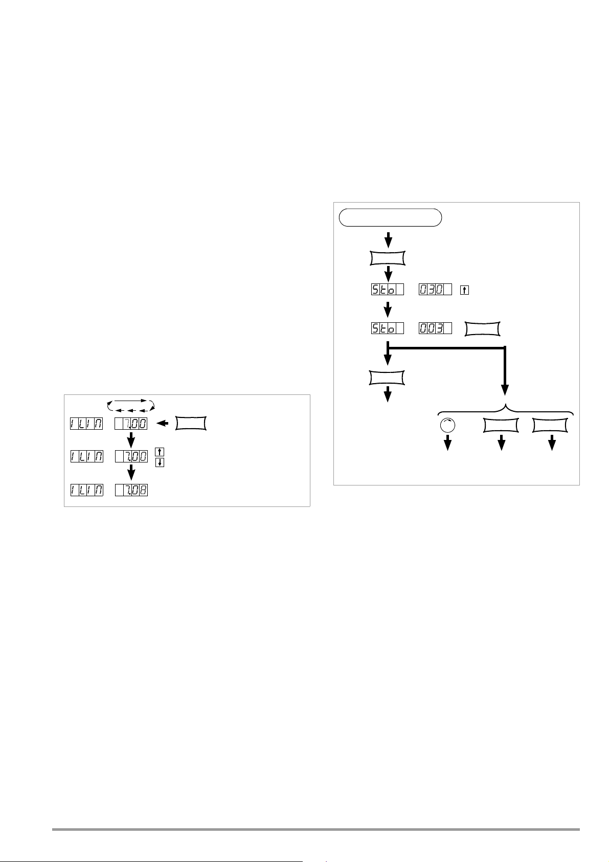
Display of Data Stored to Sequence Memory (11 ... 255) Upon
Cursor position
SELECT
Setting resolution of
the numeric parameter
CE/LOCAL
Basic Settings
FUNCTION RCL
Uout/Iout
Uset/Iset
FUNCTION
MENU
RCL
MENU
ENTER
SAVE
Execution of <RCL>
After executing the <RCL> command, selecting a memory
location (<> or <> key) and pressing the <ENTER> key, the
device is switched to the read-out mode. Values saved to
sequence memory blink at the display. The settings stored to the
selected memory location can now be browsed by pressing the
<SELECT> key:
Uset Iset Voltage and current setpoints
tSEt Programmed dwell time
SSEt Signal output status
4.8.4 Setting Resolution with the <SELECT> Key
The numeric parameter can be set to varying degrees of
accuracy. Set the cursor to the desired decimal place within the
display to this end. The corresponding decimal place blinks in
order to indicate the current cursor position.
Resolution can be set for the following parameters:
Uset, Iset, Ulim, Ilim, OVset, Delay, tset and tdef.
Settings
☞
Select the desired parameter.
! The parameter value blinks at the last selected decimal place.
☞ Press the <SELECT> key. The cursor (blinking decimal place) is
moved one place to the right.
☞ Repeatedly press the <SELECT> key until the cursor is
positioned at the desired decimal place.
☞ Set the parameter to the desired value with the <> key or the
<> key using the selected resolution.
Settings
☞
Select values for the desired parameters.
☞ Press the <SAVE> key.
! Sto appears at the left-hand display, and the last selected
memory location number appears at the right-hand display.
☞ Select the desired memory location (1 to 10) with the <> or
the <> key.
☞ Acknowledge by pressing the <ENTER> key.
☞ Exit the SAVE function by pressing the <CE/LOCAL> key.
☞ Switch to the respective function by pressing the <FUNCTION>
key, the <SELECT> key or the <RCL> key, or by slightly turning
the current or voltage adjusting knob.
Figure 4.8.4 Setting Resolution with the SELECT Key
4.9 Storing Data with the <SAVE> Key
The <SAVE> key is located at the left-hand side of the front panel
in the second row of keys underneath the <FUNCTION> key.
It makes the following functions available:
• Saving basic device settings
• Saving data to a Memory Location
• Deleting all data within a defined memory range from address
11 to 255
• Inserting additional data to a sequence
• Deleting an individual sequence memory
4.9.1 Saving Basic Device Settings
• Basic device settings can be saved to memory locations 1
through 10.
• These settings are saved to battery-backed memory.
Settings for all of the following parameters can be saved to
this memory:
USET/ISET OVSET TSET
OCP TDEF SSET
DELAY START OUTPUT
MINMAX STOP ULIM
REPETITION ILIM
Figure 4.9.1 Saving Device Settings
4.9.2 Saving Data to a Memory Location
Functions
• Sequence data can be saved to memory locations 11 through
255.
• These settings are saved to battery-backed memory.
• Uset, Iset, Tset and Sset values can be saved.
Settings (see also page 35)
☞ Select values for the desired parameters.
☞ Press the <SAVE> key.
! Sto appears at the left-hand display, and the last selected
memory location number appears at the right-hand display.
☞ Select the desired memory location (11 to 255) with the <>
or the <> key.
☞ Acknowledge by pressing the <ENTER> key.
GMC-I Messtechnik GmbH 41
Page 42

4.9.3 Clearing the Contents of a Defined Memory Range
ENTER
SAVE
ENTER
Clear range from start to stop address
Abort
CE/LOCAL
FUNCTION RCL
Uout/Iout
Uset/Iset
FUNCTION
MENU
RCL
MENU
Example of clearing all content from start to stop address:
occupied
occupied
occupied
empty
empty
start °1 sequence °1 stop °1
start °2 sequence °2 stop °2
S | t | o |
Operation
"Clearing
content of a
memory range"
c | l | r |
The content of the memories between start
Functions
• All data are deleted from memory locations from the current
start address to the current stop address.
Settings
☞
Press the <SAVE> key.
☞ Select memory location 0 (clr) with the <> key or the <> key.
☞ Press the <ENTER> key.
! clr dAtA and start stop blink alternately at the display in order to
identify the range to be deleted.
☞ Acknowledge by pressing the <ENTER> key.
! The range of memory locations from the start address to the
stop address is cleared.
! Deletion of data can be aborted at any time by pressing the
<CE/LOCAL> key.
Figure 4.9.3 Clearing all Content from the Start to the Stop Address
01
10
011
current start
S | t | r | t S | t | o | P
c | l | r |
d | A | t | A
current stop
and stop address is empty!
255
42 GMC-I Messtechnik GmbH
Page 43

4.9.4 Inserting a Memory Location
CE/LOCAL
FUNCTION RCL
Uout/Iout
Uset/Iset
FUNCTION
MENU
RCL
MENU
ENTER
SAVE
SAVE
&
Start and stop address
Abort
All memory locations address 103 are shifted up by 1.
Memory location 103 is empty and the content of the stop address is lost.
Example of inserting an empty memory location within a given memory range:
occupied
occupied
occupied
empty empty
start °1 sequence °1 stop °1
start °2 sequence °2 stop °2
current stop
S | t | o | Y | Y | Y | i
YYY
p
p
The start and stop addresses define the working range for the
command described below. Memory locations which do not lie
within this range are protected against access when the
command is executed. Each time a memory location is inserted,
the content of the previous stop address is lost.
Functions
• Starting with the target address, previously saved data are
shifted to higher address numbers.
• Memory location content located at memory address N prior
to insertion is shifted to memory address N+1.
• Data which were previously stored to the memory location
with the stop address are lost.
• The target address has no content after initial insertion.
Attention: Currently selected start and stop addresses and start
and stop addresses saved to setup memory are not corrected
automatically!
Settings
☞
Select a start address and a stop address with the help of the
sequence submenu.
☞ Press the <SAVE> key.
! Sto and the last selected address appear at the display.
☞ Select the desired target address with the <> or the <>
key.
☞ Simultaneously press the <SAVE> and <> keys.
! An i (for insert) appears in the right-hand display next to the
selected memory address number.
☞ Execute the insert command by pressing the <ENTER> key.
! An empty memory location is added at the selected memory
address.
! The address numbers of all memory locations above the
selected address are increased by 1.
Figure 4.9.4 Inserting a Memory Location Within a Given Range
01
10
011
YYY+1
-1
Sto
Sto
Insertion
current start
The previous content of the stop address is lost!
255
GMC-I Messtechnik GmbH 43
Page 44

4.9.5 Deleting a Memory Location
CE/LOCAL
Start and stop address
FUNCTION RCL
Uout/Iout
Uset/Iset
FUNCTION
MENU
RCL
MENU
ENTER
SAVE
SAVE
&
Content of memory location 103 (n) is overwritten by content from location 104 (n+1).
The stop address has no content.
Abort
Example of deleting an individual SEQUENCE memory location:
occupied
occupied
occupied
empty empty
start °1 sequence °1 stop °1
start °2 sequence °2 stop °2
current stop
YYY
S | t | o |
p
p
current stop
The start and stop addresses define the working range for the
command described below. Memory locations which do not lie
within this range are protected against access when the
command is executed. Each time a memory location is deleted,
an empty memory location is inserted at the stop address.
Functions
• Starting with the target address, previously saved data are
shifted to lower address numbers.
• Memory location content located at memory address N prior
to deletion is shifted to memory address N-1.
• Data which were previously stored to the memory location
with the target address are lost.
• The stop address has no content after initial deletion.
Attention: Currently selected start and stop addresses and start
and stop addresses saved to setup memory are not corrected
automatically!
Settings
☞
Select a start address and a stop address with the help of the
sequence submenu.
☞ Press the <SAVE> key.
! Sto and the last selected address appear at the display.
☞ Select the desired target address with the <> or the <>
key.
☞ Simultaneously press the <SAVE> and <> keys.
! A d (for delete) appears in the right-hand display next to the
selected memory location address number.
☞ Execute the delete command by pressing the <ENTER> key.
! The address numbers of all memory locations within the start
to stop address range above the selected address are
decreased by 1.
Figure 4.9.5 Deleting an Individual SEQUENCE Memory Location
01
10
011
current start
Deletion
current start
-1
YYY+1
Sto
Y | Y | Y | d
-1
YYY
Sto
The new content of the stop address is empty!
255
44 GMC-I Messtechnik GmbH
Page 45
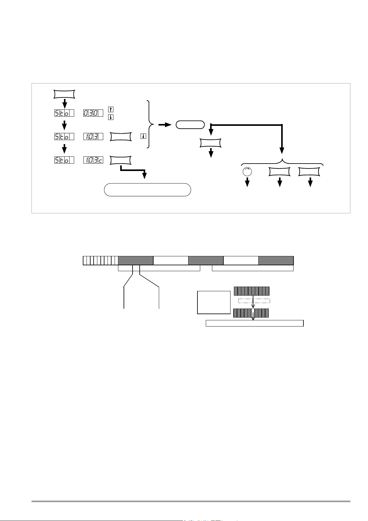
4.9.6 Deleting the Contents of a Memory Location
CE/LOCAL
FUNCTION RCL
Uout/Iout
Uset/Iset
FUNCTION
MENU
RCL
MENU
ENTER
SAVE
SAVE
&
Abort
Content of location 103 is deleted.
Example of deleting the content of an individual memory location:
occupied
occupied
occupied
empty
empty
start °1 sequence °1 stop °1
start °2 sequence °2 stop °2
current stop
p
S | t | o |
Operation
"Deleting the
content of a
start an d stop address
Functions
• The contents of any desired individual memory location from
address 11 through 255 can be deleted.
• This has no effect on other memory addresses.
Settings
☞
Press the <SAVE> key.
! Sto and the last selected address appear at the display.
☞ Select the desired address with the <> key or the <> key.
☞ Press the
<SAVE> and <CE/LOCAL> keys simultaneously.
! A c (for clear) appears in the right-hand display next to the
selected memory location address number.
☞ Execute the delete command by pressing the <ENTER> key.
Figure 4.9.6 Deleting the Contents of an Individual Memory Location
01
10
011
current start
4.10 Memory Recall with the <RCL> Key
• All device settings saved to memory with <SAVE> or STORE can
be recalled with the <RCL> key (RECALL), e.g. in order to
reconfigure the device. This memory is battery-backed.
• Empty memory locations are displayed as “----” “----”, and
cannot be recalled. ERR 24 appears briefly at the display, and
bit 5 is set in event register B.
• RCL can also be controlled via the analog interface (see
page 28 and chapter 5.8).
4.10.1 Recall from SETUP Memory
Addresses 1 through 10: complete basic device settings
USET OVset OCP START
ISET Ulim DELAY STOP
Tset Ilim MINMAX REPETITION
Sset OUTPUT Tdef
GMC-I Messtechnik GmbH 45
-1
Sto
Independent of current
YYY
Y | Y | Y | c
memory"
The content of the selected memory is empty!
255
Settings
☞
Press the <RCL> key.
! rcl appears at the left-hand display, and the last selected
memory location number appears at the right-hand display.
☞ Select the desired address [1 ... 10] by pressing the <> key
or the <> key.
☞ Press the <ENTER> key.
! Iset and Uset settings saved to this address blink at the
display.
☞ Browse through this memory location with the <SELECT> key
in order to view the respective parameter settings (see chapter
4.8).
☞ All of the data saved to this memory location can now be
loaded as basic settings by once again pressing the <ENTER>
key.
☞ Press the <CE/LOCAL> key to abort the RECALL function.
☞ Press the <RCL> key in order to return to the memory location
selection function.
☞ The RECALL function can be exited by pressing any other
function key, or by turning the adjusting knob.
Page 46

4.10.2 Recall from SEQUENCE Memory
Addresses 11 to 255: Uset, Iset, tSEt and SSEt values for the
sequence function
! Data from memory locations 11 through 255 can be recalled
at any time during programming.
☞ Press the <RCL> key.
! rcl appears at the left-hand display, and the last selected
memory location number appears at the right-hand display.
☞ Select the desired address (11 ... 255) by pressing the <>
key or the <> key.
☞ Acknowledge your selection with the <ENTER> key.
!
Iset and Uset settings saved to this address blink at the display.
☞ Browse through this memory location with the <SELECT> key
in order to view the respective parameter settings (see chapter
4.8).
☞ All of the data saved to this memory location can now be
loaded by once again pressing the <ENTER> key.
! If one of the recalled Uset or Iset values exceeds the currently
valid soft limit (Ulim and Ilim), execution of the command is
aborted, Err 21 is displayed briefly and bit 5 is set in event
register B.
! Only Uset, Iset and SSEt are executed: tset is loaded as a
current setting value but is not executed.
☞ Another memory location can be immediately accessed with
the <> key or the <> key while the previous function is
being executed.
☞ Press the <CE/LOCAL> key to abort the RECALL function.
☞ Press the <RCL> key in order to return to the memory location
selection function.
☞ The RECALL function can be exited and another function
accessed by pressing any other function key, or by turning the
adjusting knob.
4.11 Disabling Front Panel Controls
The front panel controls can be disabled against inadvertent
changes to selected values and settings.
The behaviour during mains ON is also influenced by the selected
power-on status Pon parameter (page 26).
Disabling
☞
Simultaneously press the <CE/LOCAL> and <SAVE> keys.
! The front panel controls are now disabled.
! The yellow LOCKED/SEQ LED lights up.
Enabling
☞
Press and hold the <CE/LOCAL> key for at least 4 seconds, or
until the LOCKED/SEQ LED goes out.
Note: While key is pressed and sequence is in progress, „LLO“ is
shown in the display.
Disabling and Enabling via the Analog Interface
☞
The <CE/LOCAL> key can also be disabled by applying a signal
to the trigger input at the analog interface and selecting the
appropriate setting for the T_MODE function, thus preventing
manual reactivation of the front panel controls.
4.12 <The ENTER> Key
The <ENTER> key is used to execute various functions in
combination with the respectively selected operating mode.
<ENTER> Key Functions
Pre-Selecting Setpoints (fixed value selection)
1) <ENTER>: Change display from Uout/Iout to Uset*/Iset.
2) <> or <>: Preselect Uset, Uset LED blinks.
3) <ENTER>: Activate Uset value.
4) <ENTER>: Change to Iset*.
5) <> or <>: Preselect Iset, Iset LED blinks.
6) <ENTER>: Activate Iset value.
* The decimal place which can be adjusted with the <SELECT>
function blinks.
See also page 21, “Pre-Selected Settings”.
Activating Parameter Values
Textual or numeric parameter values are activated with the
<ENTER> key during device setup.
Executing Commands
<SAVE>: Save data to the selected address.
<RCL>: Recall data saved to the selected address.
ENTER
the <
are then executed after pressing the <
Sequence control: Execution of SEq xxxx commands
Function group selection: Access parameter settings for the
selected function group
Sequence and Step-by-Step Control
A running sequence can be suspended by pressing the <
A suspended sequence can be resumed by pressing the <
The next memory location can be executed by pressing the
<ENTER> key in the step-by-step control mode.
> key the first time, the selected data blink at the display, and
ENTER
> key once again.
Status change: RUN HOLD
Status change: HOLD RUN
After pressing
ENTER
> key.
ENTER
> key.
4.13 The <CE/LOCAL> Key
The <CE/LOCAL> key is used to execute a specific function in
combination with the respectively selected operating mode.
Reset Device Settings
☞
<CE/LOCAL> key + <ENTER>: The KONSTANTER’s factory
default settings are used.
Disable and Enable Front Panel Controls
See chapter 4.11.
Switch from REMOTE to LOCAL
See chapter 4.16.
Abort an Operation
Uset / Iset Entry
☞ <CE/LOCAL> key
Switch to display of measured Uout and Iout values.
<SELECT> Display
☞ <CE/LOCAL> key
Switch to display of measured Uout and Iout values.
<SAVE> / <RCL> Function
☞ <CE/LOCAL> key
Abort <SAVE> and <RCL> functions, switch to display of
measured Uout and Iout values.
Function Group Selection
☞
<CE/LOCAL>
Return to display of measured Uout and Iout values from
function group selection.
46 GMC-I Messtechnik GmbH
Page 47

Function Selection
☞
<CE/LOCAL> key: Abort function selection, return to function
group selection.
Text Parameters
☞
<CE/LOCAL> key
Abort selection, switch to display of selected text parameter.
Sequence Control
☞ <CE/LOCAL> key
Abort a suspended sequence or step-by-step control at the
current memory location.
4.14 INCR <> and DECR <> Keys
The increment and decrement keys execute various functions
depending upon settings.
Parameter Selection
Text parameters
<>/<>: Display next or previous parameter.
Acknowledge the respective text parameter with the
<ENTER> key.
Abort with rotary knob, or with <CE/LOCAL>, <RCL>,
<SAVE> or <FUNCTION> key.
Numeric parameters
<>/<>: Increase / decrease the value of the parameter at
the cursor position.
<RESOL> is used to move the cursor.
The respective numeric parameter is activated automatically.
Exception:
Settings for Uset and Iset initialized with the <ENTER> key
(setpoint settings) and selected with the <> or the <> key
must also be acknowledged with the <ENTER> key.
Memory Location Selection
After Pressing <RCL> or <SAVE>:
<>/<>: Select next or previous memory location.
Address by Address Preview of Stored Setpoints:
After pressing <RCL>: <>/<> 11 ... 255 <ENTER>:
Blinking display of USET, ISET, TSET and SSET setpoints, can
be selected with <SELECT>, browse though addresses in the
background with selected setpoint using <> or <>, the
respective stored setpoint is displayed.
Browsing through Submenus
Function Menu
<FUNCTION> + <> or <>:
Switch to next or previous function or function group.
Select Menu
<SELECT> + <>/<>:
Select the next or the previous display function.
Executing the Next or the Previous Memory Location
in Step-by-Step Control Mode
After executing SEQ Strt or SEQ StEP with a running or a
suspended sequence, the next or the previous memory
location can be executed with <> or <>.
4.15 Device RESET
Most device functions can be returned to a defined default value
with the reset command, see page 63.
☞ Press and hold the <CE/LOCAL> key, and then press the
<ENTER> key.
4.16 Selecting Remote and Local Control Modes
After switching mains power on, the manual operating mode is
always active (local state). All front panel controls are enabled and
the device can be operated manually.
LOCAL —> REMOTE
– Switching from manual to remote control
Switching to remote control occurs:
At the IEC bus when the REN line is activated by the controller
and the device is addressed as a listener.
At the serial interface as soon as data are transmitted to the
device.
a) REMOTE LOCAL
– Switching from remote to manual control
The device is returned to manual operation:
Manually:
– By activating the <CE/LOCAL> key, as long as it has not
been disabled by the controller during IEC bus operation
( c)
Via the IEC bus:
– By transmitting the addressed GTL (GO TO LOCAL) interface
command to the device (selective switching to manual
operation)
Programming example (HP Basic): LOCAL 712 or
– If the REN line is deactivated by the controller (switches all
devices to manual operation)
Programming example (HP Basic): LOCAL 7
LOCAL LOCKOUT
– Disabling manual switching to manual operation
(only relevant for control via the IEC bus)
The IEC bus controller can disable the LOCAL key at the
device with the LLO (LOCAL LOCKOUT) universal interface
command, preventing manual switching to the manual
operating mode (remote state with lock).
Programming example (HP Basic): LOCAL LOCKOUT 7
Comments
The “REMOTE” LED indicates the momentary control mode:
LED on = remote control
LED off = manual control
Switching back and forth between the two control modes does
not cause any changes to current device settings or stored
parameters.
Exception: If the display has been switched off it is reactivated
when switching from REMOTE to LOCAL (DISPLAY OFF —>
DISPLAY ON).
IEC bus control: The device is capable of receiving programming
data in the manual operating mode, but they are not executed.
GMC-I Messtechnik GmbH 47
Page 48

5 Analog Interface
SIG1 OUT
SIG2 OUT
TRG IN -
TRG IN +
+15 V
AGND
Uset -
Uset +
Iset +
U MON
I MON
SENSE
OUT
OUT
+ SENSE
20
OUT
IN
ADJ
1.5 k
10 k
10 k
10 k
+
9k8
9k4
T
110 mA
+ OUT
+ OUT
+
-+-
81
81
120 k
120 k
R
a
R
b
+18 V
U-Reg.
I-Reg.
U-Reg.
I-Reg.
Ra = Rb = 60 k for 20 V types
30 k for 40 V types
15 k for 80 V types
ANALOG INTERFACE
OUTPUT
5 k
P
Controlled
37.5 k for 32 V type
U-MON (output)
Analog voltage output signal, proportional to output voltage
5.1 Connector Pin Assignments
SIG1 OUT, SIG2 OUT (output)
Digital status signal outputs with reference to AGND
SIG1 OUT indicates the status defined by SIG1 txt.
SIG2 OUT indicates the status defined by SIG2 txt.
Signal type Open collector
Max. switching voltage 30 V DC
Max. switching current 20 mA
☞ For a detailed description refer to chapter 5.3.
TRG IN+, TRG IN- (input)
Uout acquired by the sensing leads.
(0 ... 10 V 0 ... Uout
).
nom
The short-circuit proof output is referenced to AGND, has an
internal resistance of 9.8 k and is short-circuit proof.
☞ For a detailed description refer to chapter 5.6.
I-MON (output)
Analog voltage output signal, proportional to output current
(0 to 10 V 0 ... Iout
The short-circuit proof output is referenced to AGND, has an
internal resistance of 9.4 k and is short-circuit proof.
).
nom
☞ See detailed description in chapter 5.7.
Floating, digital control input for controlling a device function
assigned with trG txt.
Low signal: – 26 V U
High signal: 4 V U
I
= (Us – 2 V) / 1.5 k
s
1 V
s
26 V,
s
☞ For a detailed description refer to chapter 5.8.
+15 V (output)
This auxiliary voltage output (15 to 17 V DC with reference to
AGND) can be used to control the trigger input, or to supply
power to external components (e.g. reference element for
generating control voltages).
The output is equipped with electronic current limiting to
approximately 60 mA, and is short-circuit proof to AGND.
AGND (analog ground = reference point)
Reference point for analogue control inputs and outputs.
This terminal is internally connected to the minus pole of the
Uset-, Uset+ (input)
Analog (differential) voltage input with reference to AGND for
Uout = USET + U
power output via an auto-reversible fuse with a rating of
110 mA.
controlling output voltage. The following applies when the
output is activated:
Uout = Output voltage in constant voltage regulating mode
su
k
u
USET = Voltage setpoint selected in manual mode
U
su
k
u
R
su
☞ For a detailed description refer to chapter 5.4.
Iset+ (input)
= External control voltage (0 to 5 V 0 ... Uout
= Control coefficient = Uout
= Input resistance (Uset +: 10 k)
Uset–: 15 k
nom
/ 5 V
Analog voltage input with reference to AGND for controlling
output current. The following applies when the output is
activated:
Iout = ISET + U
Iout = Output current in constant current regulating mode
k
si
i
ISET = Current setpoint selected in manual mode
U
= External control voltage (0 to 5 V 0 ... Iout
si
= Control coefficient = Iout
k
i
R
= Input resistance: 10 k
si
nom
/ 5 V
nom
nom
)
)
☞ For a detailed description refer to chapter 5.5.
48 GMC-I Messtechnik GmbH
Figure 5.1 Internal Wiring of Analog Interface and Output
(simplified representation)
Page 49

5.2 Auto-Sensing Mode
SSP KONSTANTER
Settings
USET = Uset
ISET = Iset
+ SENSE
OUT
OUT
SENSE
Analog Interface
SIG1 OUT
SIG2 OUT
TRG IN
TRG IN
+15 V
AGND
Uset
Uset +
Iset +
U-MON
I-MON
+ OUT
+ OUT
Uout
Load
Iout
Output
R
PU
OUTPUT ON
+5 V
Usig
Figure 5.3
Wiring Examples for
Status Signal Outputs
In order to be able to take advantage of highly constant output
voltage at the power consumer even if long leads are used,
sensing leads can be used to compensate for voltage drops
within the output leads.
Functions
Sensing lead terminals +SENSE and –SENSE
Acquirement of output voltage, which decisively influences the
voltage measuring and control circuits, directly at the power
consumer (instead of at the output terminals).
Sensing mode operation (remote sensing) offers the following
advantages:
- In the constant voltage regulating mode, current related voltage
drops occurring in the output leads have practically no effect on
voltage supplied to the power consumer.
- Voltage at the output terminals is automatically increased to
compensate for voltage drops.
- In the constant current regulating mode, voltage limiting at the
consumer is independent of output current.
- The voltage value read out by the measuring function
indicates voltage acquired at the sensing leads. Load parameters
such as power consumption and load resistance can thus be
determined more accurately.
The parameters and limit values included in figure in figure 5.2
and in the section entitled Electrical Data apply for operation
with the sensing leads.
Incorrect connection of the sensing leads does not damage the
KONSTANTER, although it results in the following reversible events:
- Polarity reversal at sensing leads or interrupted output lead
If output voltage is not being limited at the KONSTANTER by
means of current regulation, it climbs to well above the
selected value.
This condition immediately triggers overvoltage protection
and deactivates the output.
- Interruption of a sensing lead
Automatic reset to local sensing for the respective output
pole.
If the sensing leads have been connected incorrectly,
increasing voltage between the output terminals is not
acquired by the measuring function.
Activation
The remote sensing mode function is activated automatically
after the SENSE terminals have been connected to the power
consumer at the respective output poles.
The function is deactivated by once again interrupting this
connection.
5.3 Status Signal Outputs
Functions
The KONSTANTER is equipped with two open collector
outputs with reference to AGND for reading out status signals,
namely SIG1OUT and SIG2OUT.
The device status or event to be signaled is independent for
both signal outputs.
Selection is made by setting the SIG1 and SIG2 functions.
A detailed description is included on page 29 for manual
operation, and on page 71 for programming.
As a status signal for monitoring devices
For controlling external output relays
Applications
Triggering of certain device functions can be synchronized by
means of connection to the trigger inputs of other
Figure 5.2 Connecting the Power Consumer for
Sensing Mode Operation
Cs+, Cs-10 F ... 220 F
U
s+,Us-
I
s+
I
s-
1 V
Us+ / 81
Us- / 81
Connection
The +SENSE and –SENSE sensing leads from the output
connector plug at the rear panel should be connected as close
as possible to the power consumer.
Connect each respective sensing lead to the appropriate output
pole (+SENSE: +, –SENSE: –).
Interference can be minimized by:
- Twis ti ng the sensing leads and/or
- Shielding the sensing leads (connect shield to ground, the
housing or the negative output pole)
Long output and sensing lead impedances may result in control
fluctuations at the output.
This problem is of course worsened by capacitive consumers.
Control fluctuations can be counteracted with one capacitor
GMC-I Messtechnik GmbH 49
each (C
, Cs-) between the SENSE and output terminals (see
s+
Figure 5.2).
If the output leads are twisted, their impedance can be reduced
as well.
KONSTANTERs (see also chapter 5.9.2).
Connection
Values for connection:
Max. switching voltage: 30 V DC
Max. switching current: 20 mA
If you want to use the signal outputs to send status signals to
external monitoring devices, pull-up resistors must be used in
order to generate appropriate levels.
The status signal outputs can be connected to the +15 V
terminal with pull-up resistors (at least 1 k), in order to
generate an active high signal of +15 V.
Page 50

5.4 Regulating Output Voltage
Attention!
!
+ SENSE
OUT
OUT
SENSE
Analog Interface
SIG1 OUT
SIG2 OUT
TRG IN
TRG IN
+15 V
AGND
Uset
Uset +
Iset +
U-MON
I-MON
+ OUT
+ OUT
Output
Settings
USET = 0
ISET = Iset
OUTPUT on/off
+ SENSE
OUT
OUT
SENSE
Analog Interface
SIG1 OUT
SIG2 OUT
TRG IN
TRG IN
+15 V
AGND
Uset
Uset +
Iset +
U-MON
I-MON
+ OUT
+ OUT
Output
Settings
USET = 0
ISET = Iset
OUTPUT on/off
Load
Uout
Iout
Uout
Load
a)
Iout
Isu
b)
REF 02
IN
OUT
+5V
2k
Usu
SSP KONSTANTER
SSP KONSTANTER
USET+
USET–
AGND
ISET+
AGND
+ SENSE
OUT
OUT
SENSE
Analog Interface
SIG1 OUT
SIG2 OUT
TRG IN
TRG IN
+15 V
AGND
Uset
Uset +
Iset +
U-MON
I-MON
+ OUT
+ OUT
Output
Settings
USET = Uset
ISET = 0
OUTPUT on/off
+ SENSE
OUT
OUT
SENSE
Analog Interface
SIG1 OUT
SIG2 OUT
TRG IN
TRG IN
+15 V
AGND
Uset
Uset +
Iset +
U-MON
I-MON
+ OUT
+ OUT
Output
Settings
USET = Uset
ISET = 0
OUTPUT on/off
Uout
Load
Uout
I
si
Iout
Usi
REF 02
IN
OUT
+5V
2k
Load
Iout
SSP KONSTANTER
SSP KONSTANTER
5.5 Regulating Output Current
Functions
Output voltage Uout can be set by means of an external control
voltage U
via control inputs Uset+ (non-inverting) and Uset
su
(inverting).
The following applies in the constant voltage regulating mode:
Uout = USET + Usu k
su
USET = selected voltage setpoint
k
= voltage control coefficient = Uout
su
Max. adjusting error: 0.05% v. U
2% of the setting value
nom
nom
/ 5 V
The voltage control input functions as a differential voltage
input:
Uset+ = non-inverting input:
= 0 ... + 5 V for Uout = 0 V ... Uout
U
su
nom
input resistance: 10 k
Uset = inverting input:
Usu = 0 ... 5 V for Uout = 0 V ... Uout
nom
,
input resistance: 15 k
Notes:
The control inputs are not floating inputs: Their reference point,
AGND, is connected to the negative pole of the power output.
Connecting grounded circuits to the control input may result in
erroneous settings due to leakage current or ground loops.
If the reference point of control voltage U
negative output pole at the load side, the inverting input must
be connected to this point (connection b in Figure 5.4).
Influences resulting form voltage drops in the output lead are
thus avoided.
If control voltage is isolated from the output, connect Uset to
AGND (connection a in Figure 5.4).
If remote adjustment of output voltage is to be accomplished by
means of a potentiometer, wiring can be laid out as shown in
Figure 5.4.
U
can be applied as an alternating voltage, for example in order
su
to superimpose the selected direct voltage USET with
interference signals.
The cut-off frequency of the modulated output voltage depends
upon voltage amplitude.
To a great extent, cut-off frequency remains independent of
the magnitude of the load and selected current limiting thanks
to a special circuit design.
is connected to the
su
Functions
Output current Iout can be set with an external voltage Usi via
the control input Iset+.
The following applies in the constant current regulating mode:
Iout = ISET + U
k
si
si
ISET = selected current setpoint
k
= current control coefficient= Iout
si
Max. adjusting error: 0.1% of I
2% of setting value
nom
nom
/ 5 V
Current control input
Iset + = non-inverting input:
= 0 ... + 5 V for Iout = 0 A ... Iout
U
si
nom
Input resistance is 10 k.
Notes:
The control input is not a floating input: Its reference point, AGND,
is connected to the negative pole of the power output.
Connecting grounded circuits to the control input may result in
erroneous settings due to leakage current or ground loops.
Control voltage U
pole at the load side. (Figure 5.5)
If remote adjustment of output current is to be accomplished by
means of a potentiometer, wiring can be laid out as shown in
Figure 5.5.
Usi can be applied as an alternating voltage, for example in order
to superimpose the selected direct current ISET with
interference signals.
The cut-off frequency of the modulated output current depends
upon the voltage amplitude which results from load.
Control inputs Uset+, Uset– and Iset+ should only be
connected with shielded cable.
Connect the shield to the AGND reference point.
may not be connected to the negative output
si
Connection
Figure 5.4 Wiring for Controlling Output Voltage with External
50 GMC-I Messtechnik GmbH
Voltage / External Potentiometer
Connection
Figure 5.5 Wiring for Controlling Output Current with External Voltage /
External Potentiometer
Page 51

5.6 Voltage Monitoring Output
k
load
=
R
load
R
load
+ 9.8 k
, load coefficient
+ SENSE
+ OUT
-OUT
-SENSE
Analog Interface
SIG1 OUT
SIG2 OUT
TRG IN
TRG IN +
+15 V
AGND
Uset -
Uset +
Iset +
U-MON
I-MON
Uout
Load
Iout
Settings
USET = Uset
ISET = Iset
OUTPUT on/off
-OUT
+ OUT
V
U
MU
+
OUTPUT
R
load
SSP KONSTANTER
k
load
=
R
i
Ri + 9.4 k
, load coefficient
+ SENSE
+ OUT
-OUT
-SENSE
Analog Interface
SIG1 OUT
SIG2 OUT
TRG IN
TRG IN +
+15 V
AGND
Uset -
Uset +
Iset +
U-MON
I-MON
Settings
USET = Uset
ISET = Iset
OUTPUT on/off
-OUT
+ OUT
Uout
Load
Iout
V
R
load
U
MI
+
OUTPUT
SSP KONSTANTER
5.7 Current Monitoring Output
Functions
The U-MON terminal reads out a voltage UMU with reference to
AGND, which is proportional to output voltage Uout.
U-MON serves as a control voltage for master-slave series
connection (see chapter 5.10.2).
However, U-MON can also be used for external measuring,
monitoring and recording.
The following applies:
U
= Uout kMU k
MU
kMU = 10 V / Uout
R
i (U-MONITOR)
R
= load resistance
load
Max. error for U
= 0 ... 10 V
l
Be
, U-Monitor coefficient
nom
= 9.8 kU-Monitor internal resistance
: 5 mV 1% of actual value (where R
MU
load
10 M)
Notes:
U-MON is not a floating output: Its reference point, AGND, is
connected to the negative output pole.
Connecting grounded measuring circuits to the monitor output
may result in erroneous measurements due to leakage current or
ground loops.
The voltage monitoring output makes reference to output
voltage acquired at the sensing leads (see chapter 5.2).
The monitor output is short-circuit proof.
Internal resistance is 9.8 k.
Connection
Functions
The I-MON terminal reads out a voltage UMI with reference to
AGND, which is proportional to output current Iout.
I-MON serves as a control voltage for master-slave parallel
connection (see chapter 5.9.2).
However, I-MON can also be used for external measuring,
monitoring and recording.
The following applies:
U
>
= Iout kMI k
MI
= 10 V / Iout
k
MI
R
i (I-MONITOR)
R
= load resistance
load
Max. error for U
10 M)
: 5 mV 1% of actual value (where R
MI
= 0 ... 10 V
load
, I-Monitor coefficient
nom
= 9.4 kI-Monitor internal resistance
Notes:
I-MON is not a floating output: Its reference point, AGND, is
connected to the negative output pole.
Connecting grounded measuring circuits to the monitor output
may result in erroneous measurements due to leakage current or
ground loops.
The monitor output is short-circuit proof.
Internal resistance is 9.4 k.
Connection
load
>
Figure 5.7 Current Monitor Wiring
Figure 5.6 Voltage Monitor Wiring
GMC-I Messtechnik GmbH 51
Page 52

5.8 Trigger Input
Warning!
Attention!
!
+ SENSE
OUT
OUT
SENSE
Analog Interface
SIG1 OUT
SIG2 OUT
TRG IN
TRG IN
+15 V
AGND
Uset
Uset +
Iset +
U-MON
I-MON
+ OUT
+ OUT
Output
SSP KONSTANTER
SSP KONSTANTER
+ SENSE
OUT
OUT
SENSE
Analog Interface
SIG1 OUT
SIG2 OUT
TRG IN
TRG IN
+15 V
AGND
Uset
Uset +
Iset +
U-MON
I-MON
+ OUT
+ OUT
Output
Settings
USET = Uset
ISET = Iset
T_MODE OFF
Settings
USET = Uset
ISET = Iset
T_MODE OFF
Uout
Load
Uout
Iout
Load
Iout
I
s
U
s
Is approx. 10 mA
+ SENSE
OUT
OUT
SENSE
Analog Interface
SIG1 OUT
SIG2 OUT
TRG IN
TRG IN
+15 V
AGND
Uset
Uset +
Iset +
U-MON
I-MON
+ OUT
+ OUT
Output
Settings
USET = Uset
ISET1+2+3 = Iset
OUTPUT on/off
+ SENSE
OUT
OUT
SENSE
Analog Interface
SIG1 OUT
SIG2 OUT
TRG IN
TRG IN
+15 V
AGND
Uset
Uset +
Iset +
U-MON
I-MON
+ OUT
+ OUT
Output
Settings
USET = Uset
ISET1+2+3 = Iset
OUTPUT on/off
+ SENSE
OUT
OUT
SENSE
Analog Interface
SIG1 OUT
SIG2 OUT
TRG IN
TRG IN
+15 V
AGND
Uset
Uset +
Iset +
U-MON
I-MON
+ OUT
+ OUT
Output
Settings
USET = Uset
ISET1+2+3 = Iset
OUTPUT on/off
Load
= Only required for sensing mode operation
SSP KONSTANTER
SSP KONSTANTER
SSP KONSTANTER
5.9 Parallel Connection
Functions
The TRG IN floating optocoupler input allows for remote control of a
device function using a binary signal.
The function to be controlled is selected with the T-MODE
setting (in the trG display).
☞ A detailed description is included on page 28 and page 74.
Connection
Connect the control signal between TRG IN+ and TRG IN-. Refer
to the table below for the respective signal level.
Output Signal U
s
OFF High 4 ... 26 V DC (Us 2 V) / 1.5 k
ON Low 0 ... 1 V DC 0 mA
The TRIGGER input can be driven with the +15 V output at the
analog interface via any desired switch (Figure 5.8).
The TRG IN trigger input is a floating input and is
functionally isolated from the output current circuit.
This functional isolation is not equivalent to “safety
separation” as specified in electrical safety regulations.
Note
The trigger input is scanned roughly every 10 ms by the digital
control unit. After a signal change has been detected, repeated
querying ensues at short time intervals (suppression of switch
bouncing and interference pulses). This means that:
– Trigger signal pulses must have a minimum duration of
14 ms in order to assure reliable recognition.
– A delay of 1 to 15 ms may occur between application of the
control signal and triggering of the controlled function.
I
s
If output current from a single KONSTANTER is insufficient for the
respective application, the outputs of any number of
KONSTANTERs can be parallel connected.
If outputs with different nominal voltages are parallel
connected, all outputs must be limited to the lowest
utilized nominal voltage value. The ULIM parameter is
used to select this setting.
5.9.1 Direct Parallel Connection
Functions
Easiest way to provide the power consumer with more current
than is available from a single KONSTANTER
KONSTANTERs with differing nominal output voltages can be
used. However, all voltage setpoints must be set or limited to the
same value.
Less suitable for constant voltage regulating mode
Connection
Figure 5.9.1 a Wiring for Direct Parallel Connection
Settings
Deactivate all outputs.
Adjust voltage setpoint USET of all parallel connected
KONSTANTERs to approximately the same value:
Uset = USET1 = USET2 = USET3 = USETn
Adjust current setpoints ISET such that they add up to the desired
cumulative current value Iset:
Iset = ISET1 + ISET2 + ISET3 + ... + ISETn
Activate the outputs.
Figure 5.8 Controlling the Trigger Input with a Switching Element /
External Signal
52 GMC-I Messtechnik GmbH
Functional Principle
After switching the outputs on, load current is initially supplied
by the KONSTANTER with the highest voltage setting.
If load resistance is continuously reduced, load current is
continuously increased.
When load current reaches the ISET value selected for the output
which is momentarily supplying power to the consumer, current
limiting is activated for this output.
If load resistance is further decreased, current regulation reduces
output voltage until the voltage value of the output with the next
lowest setting is reached.
As of this point in time, this KONSTANTER also supplies a
portion of the load current.
Page 53

This procedure is continued until load current triggers current
Ideal working
current
Ideal working range
for voltage regulation
at the load
U
out1
U
out2
U
out3
I
out1
I
out2
I
out3
R
L
R
L
U
A
/ V
I
A
/ A
range for
regulation at
the load
regulating at the output with the lowest voltage setting when
the setpoint value for cumulative current is reached.
This output maintains constant load current until the load
resistor is short-circuited.
Figure 5.9.1 b U/I Diagram for Direct Parallel Connection
Notes:
Slightly varying voltages occur at the individual outputs as a
result of setting tolerances.
In the event of larger voltage differences, an electronic sink is
activated at the outputs with lower voltage settings.
The sink attempts – in some cases in pulse mode – to reach the
lower voltage value.
Neither the KONSTANTERs nor the power consumer are
damaged as a result.
If problems occur with measurement of load current, the
KONSTANTERs should be linked by means of master-slave
parallel connection (see also chapter 5.9.2).
The outputs can be activated and deactivated commonly by
connecting the SIG1 outputs to the TRG inputs (see also chapter
5.9.2).
GMC-I Messtechnik GmbH 53
Page 54

5.9.2 Master-Slave Parallel Connection
+ SENSE
OUT
OUT
SENSE
Analog Interface
SIG1 OUT
SIG2 OUT
TRG IN
TRG IN
+15 V
AGND
Uset
Uset +
Iset +
U-MON
I-MON
+ OUT
+ OUT
Master
Settings
USET = Uset
ISET = Iset / n
OUTPUT on/off
+ SENSE
OUT
OUT
SENSE
Analog Interface
SIG1 OUT
SIG2 OUT
TRG IN
TRG IN
+15 V
AGND
Uset
Uset +
Iset +
U-MON
I-MON
+ OUT
+ OUT
Slave 1
Settings
USET > Uset
master
ISET = 0 A
OUTPUT on
+ SENSE
OUT
OUT
SENSE
Analog Interface
SIG1 OUT
SIG2 OUT
TRG IN
TRG IN
+15 V
AGND
Uset
Uset +
Iset +
U-MON
I-MON
+ OUT
+ OUT
Load
= only required for sensing mode operation
1 k
Slave 2
Settings
USET > Uset
master
ISET = 0 A
OUTPUT on
1 k
Output
Output
Output
R
sym
R
sym
trG out
SIG1 out
trG out
SIG1 out
SSP KONSTANTER
SSP KONSTANTER
SSP KONSTANTER
Functions
As opposed to direct parallel connection, master-slave parallel
connection offers significant advantages:
Equally suitable for voltage and current regulation
Output parameters (output voltage, cumulative current limiting,
output on/off) are set entirely by the master device.
All interconnected KONSTANTERs are equally loaded.
Connection
Define one power supply as a master device.
Connect master and slave devices as shown in Figure 5.9.2.
Connect the output leads (refer to chapter 2.1.5).
Balance the individual output current values. Keep connector
cable as short as possible, and use the largest possible
conductor cross-section. Perform balancing with RR
sym
.
Check output current at the slave device displays.
Output current at each of the slaves can be precisely matched to
master output current by adjusting R
. Changes appear
sym
immediately at the respective display.
Undo short-circuiting of the load.
From this point on, setting and regulation of (cumulative) output
parameters are controlled entirely by the master device.
Power-up after initial settings:
Devices can be switched on and off in any desired order.
Functional Principle
The master controls output current of the downstream device
(slave 1) via the slave’s current control input with the help of the
current monitoring signal.
Slave 1 functions as a master device for the next downstream
slave (slave 2), and so forth.
Cumulative output current is thus always proportional to
master output current.
The master controls the output on / off status of the slave
devices via the connection from the master SIG1 output (SIG1 out
setting) to the Slave TRG input (trG out setting).
Notes:
KONSTANTERs with Differing Nominal Values
The KONSTANTER with the smallest nominal voltage value must
always be used as the master device.
The voltage setting range of the other KONSTANTERs must be
limited to this lowest value with the ULIM parameter.
Slave output current Iout corresponds to master output current
Iout as a percentage only, relative to I
Example:
Master: SSP 120-20 U
nom
Settings: USET :12 V ISET : 3 A (30%)
Slave 1: SSP 120-20 U
Figure 5.9.2 Wiring for Master-Slave Parallel Connection
Results in Uout :12 V Iout : 3 A (30%)
Slave 2: SSP 120-40 U
Settings
Initial power-up:
Short circuit the load.
Switch the master on (mains) and configure settings:
SIG1 out
Pon rcl
OUTPUT off
USET = Uset Desired output voltage
ISET = Isoll / n Iset: Desired cumulative current
n: Number of devices
Only valid if nominal data are
identical for all devices, see notes.
Switch slave 1 on (mains) and configure:
trG out
SIG1 out
Pon rcl
USET > USET
ISET = 0 A The ISET rotary knob can be deactivated if
Use the same procedure for additional slave devices.
Press the OUTPUT ON key at the master. All slave outputs are
switched on simultaneously and configured.
54 GMC-I Messtechnik GmbH
The voltage setpoint at the slave devices
master
must be set at least 1% higher than at the
master device, e.g. to maximum.
desired by setting ILIM to 0 A.
General
A wire connection can be used instead of R
setpoint value is required for cumulative output current. In this
case, each slave device supplies slightly more current than the
master device.
If analog interface connector cables and the sensing leads are
longer than 1 meter, shielded cable should be used.
The shield is connected to the ground terminal on the housing or
to OUT.
The master device’s measuring function acquires commonly
generated output voltage for all interconnected KONSTANTERs,
but only acquires its own output current.
The individual measured current values for each of the
interconnected KONSTANTERs must be added together in
order to arrive at cumulative output current.
Results in Uout :12 V Iout : 1.8 A (30%)
nom
nom
.
nom
20 V I
20 V I
40 V I
sym
10 A
nom
10 A
nom
6 A
nom
if no precise
Page 55

5.10 Series Connection
Warning!
Attention!
!
Settings
USET1+2+3 = Uset
ISET = Iset
OUTPUT on/off
+ SENSE
OUT
OUT
SENSE
Analog Interface
SIG1 OUT
SIG2 OUT
TRG IN +
TRG IN
+15 V
AGND
Uset
Uset +
Iset +
U-MON
I-MON
+ OUT
+ OUT
Load
= Only required for sensing mode operation
Settings
USET1+2+3 = Uset
ISET = Iset
OUTPUT on/off
+ SENSE
OUT
OUT
SENSE
Analog Interface
SIG1 OUT
SIG2 OUT
TRG IN +
TRG IN
+15 V
AGND
Uset
Uset +
Iset +
U-MON
I-MON
+ OUT
+ OUT
Settings
USET1+2+3 = Uset
ISET = Iset
OUTPUT on/off
+ SENSE
OUT
OUT
SENSE
Analog Interface
SIG1 OUT
SIG2 OUT
TRG IN +
TRG IN
+15 V
AGND
Uset
Uset +
Iset +
U-MON
I-MON
+ OUT
+ OUT
Settings
USET1+2+3 = Uset
ISET = Iset
OUTPUT on/off
Settings
USET1+2+3 = Uset
ISET = Iset
OUTPUT on/off
Output
Output
Output
D
e1
D
e2
D
e3
SSP KONSTANTER SSP KONSTANTER
SSP KONSTANTER
Ideal working range
for current regulation
at the load
Ideal working range
for voltage regulation
at the load
U
out1
U
out2
U
out3
I
out1Iout2
I
out3
R
L
R
L
If output voltage from a single KONSTANTER is insufficient, or if you
want to generate a voltage, the outputs of several KONSTANTERs
can be connected in series.
Maximum allowable cumulative voltage for series
connection is 120 V (or 240 V with grounded neutral
point).
5.10.1 Direct Series Connection
If outputs with differing nominal values are series
connected, the highest selected current value is present
at all outputs in the event of short-circuit. However, the
internal reverse-voltage protection diode is only rated for
nominal current of the respective device (see reverse
voltage withstand under Technical Data). For this reason,
all current setpoints must be set to the lowest nominal
current value of all interconnected devices.
The ILIM parameter is used to select this setting.
You can also connect a diode (D
reverse direction between the terminals of the outputs
with low nominal values. The diode must be capable of
conducting nominal current from the output with the
highest current value.
, Figure 5.10.1 a) in
e
Functional Principle
The sum of all individual output voltages is made available to the
power consumer.
If load resistance is continuously reduced, all of the outputs
deliver the same load current at first.
When load current reaches the lowest selected current setpoint
value, current regulating is triggered at the respective output.
If load resistance is further reduced, this output maintains
constant load current until its output voltage has dropped to 0 V.
If even further reduction of load current occurs, the affected
output is forced by the other outputs to generate a negative
voltage.
As of approximately 0.5 V, the internal reverse-voltage protection
diode becomes conductive.
Load current can once again climb, until current regulation is
activated at the output with the next highest current setpoint
value.
This procedure is continued until load current triggers current
regulating at the output with the highest current setpoint value.
Current is held constant by this last output until short-circuiting
occurs.
Functions
Easiest way to supply the power consumer with more voltage
than is available from a single KONSTANTER
Easy wiring
Less suitable for constant current regulating mode
Connection
Figure 5.10.1 a Wiring for Direct Series Connection
Settings
Deactivate all outputs.
Adjust current setpoint ISET of all series connected
KONSTANTERs to approximately the same value:
Iset = ISET1 = ISET2 = ISET3 = ISETn
Adjust voltage setpoints USET such that they add up to the
desired cumulative voltage value Uset:
Uset = USET1 + USET2 + USET3 + ... + USETn
Activate the outputs.
GMC-I Messtechnik GmbH 55
Figure 5.10.1 b U/I Diagram for Direct Series Connection
Note
The outputs can be activated and deactivated commonly by
connecting the SIG1 outputs to the TRG inputs (see also chapter
5.10.2).
Page 56
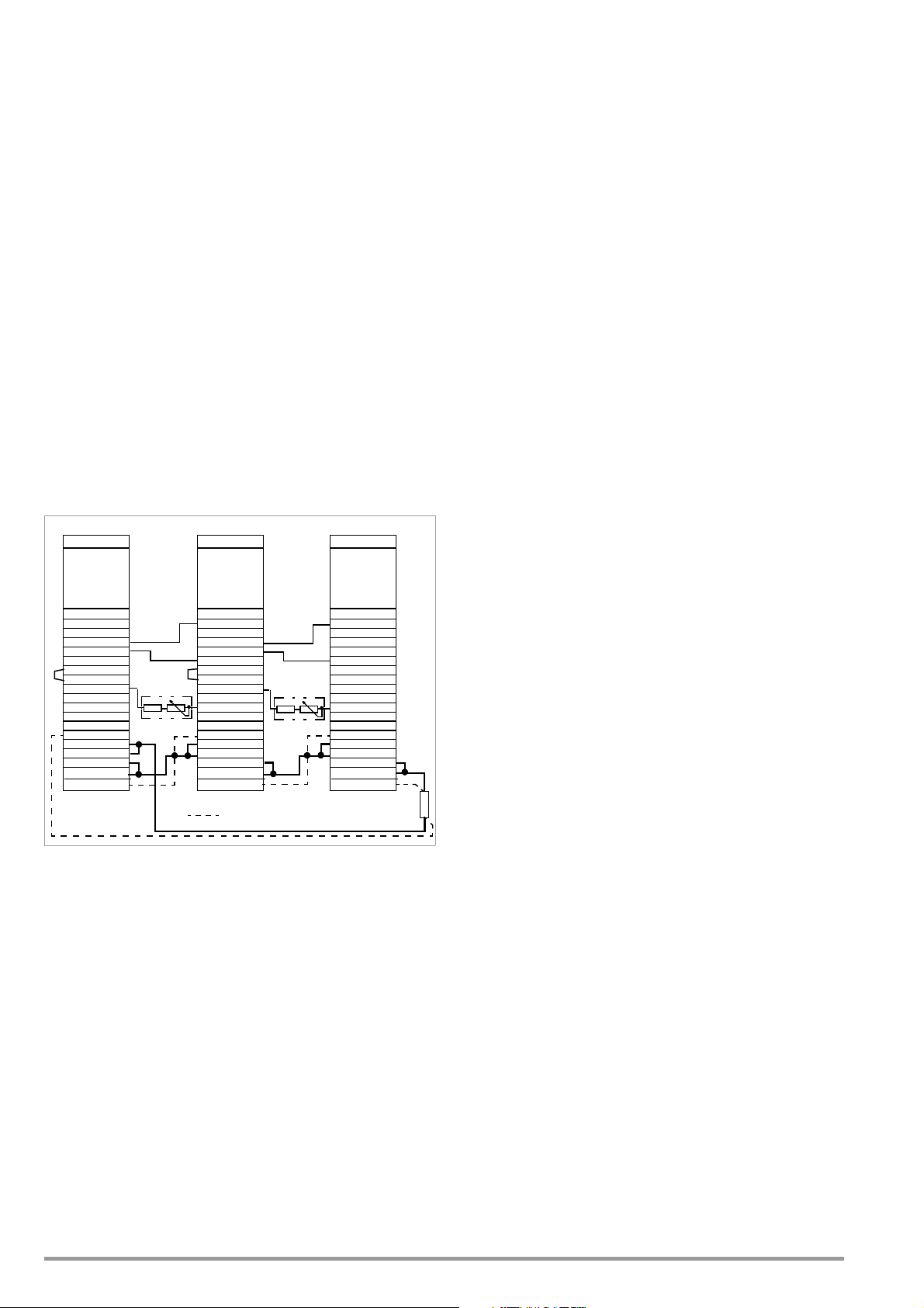
5.10.2 Master-Slave Series Connection
SSP KONSTANTER
SSP KONSTANTER
SSP KONSTANTER
+ SENSE
OUT
OUT
SENSE
Analog Interface
SIG1 OUT
SIG2 OUT
TRG IN
TRG IN
+15 V
AGND
Uset
Uset +
Iset +
U-MON
I-MON
+ OUT
+ OUT
Master
Settings
USET = Uset / n
ISET = Iset
OUTPUT on/off
+ SENSE
OUT
OUT
SENSE
Analog Interface
SIG1 OUT
SIG2 OUT
TRG IN
TRG IN
+15 V
AGND
Uset
Uset +
Iset +
U-MON
I-MON
+ OUT
+ OUT
Slave 2
Settings
USET = 0 V
ISET > Iset master
OUTPUT on
Load
R
sym
R
sym
+ SENSE
OUT
OUT
SENSE
Analog Interface
SIG1 OUT
SIG2 OUT
TRG IN
TRG IN
+15 V
AGND
Uset
Uset +
Iset +
U-MON
I-MON
+ OUT
+ OUT
Slave 1
Settings
USET = 0 V
ISET > Iset master
OUTPUT on
Output
Output
Output
= Only required for sensing mode operation
trG out
SIG1 out
trG out
SIG1 out
Functions
As opposed to direct series connection, master-slave series
connection offers significant advantages:
Equally suitable for voltage and current regulation
Output parameters (cumulative output voltage, current limiting,
output on/off) are set entirely by the master device.
All interconnected KONSTANTERs are equally loaded.
Connection
Define one power supply as a master device.
Connect master and slave devices as shown in Figure 5.10.2.
Connect the output leads to the series circuit phase terminals.
Balance the individual output voltage values with R
Balancing can be simplified and optimized by combining a fixed
resistor (metallic layer,
50 ppm / K) and a trimming resistor for R
T
k
Slave,
Nominal Voltage
R
,
sym
Nominal Value
20 V 40 k/ 0.2 W 36 k + 10 k pot
40 V 80 k/ 0.2 W 75 k + 10 k pot
80 V 160 k/ 0.2 W 150 k +20 k pot
.
sym
.
sym
R
,
sym
Combination
Switch slave 1 on and configure:
trG out
SIG1 out
Pon rcl
USET = 0 V The USET rotary knob can be deactivated if
desired by setting ULIM to 0 V.
ISET > ISET
The current setpoint at the slave devices must
master
be set at least 1% higher than at the master
device, e.g. to maximum.
Use the same procedure for additional slave devices.
Press the OUTPUT ON key at the master. All slave outputs are
switched on simultaneously and configured.
Check output voltage at the KONSTANTER displays.
Output voltage at each of the slaves
output voltage by adjusting
can be precisely
R
. Changes appear immediately at the
sym
matched
to master
respective display.
Connect the load.
From this point on, setting and regulation of (cumulative) output
parameters are controlled entirely by the master device.
Power-up after initial settings:
Devices can be switched on and off in any desired order.
Functional Principle
The master controls output voltage of the downstream
KONSTANTER (slave 1) via the slave’s voltage control input with
the help of the voltage monitoring signal.
Slave 1 functions as a master device for the next downstream
slave (slave 2), and so forth.
Cumulative output voltage is thus always proportional to
master output voltage.
The master controls the
connection
input (
from the
trG out setting
output on/off status
of the slave devices via the
master SIG1 output (SIG1 out setting
).
) to the
Slave TRG
Notes:
KONSTANTERs with Differing Nominal Values
The KONSTANTER with the smallest nominal current value must
always be used as the master device.
The current setting range of the other KONSTANTER must be
limited to this lowest value with the ILIM parameter.
Slave output voltage Uout corresponds to master output
current Uout as a percentage only, relative to U
Figure 5.10.2 Wiring for Master-Slave Series Connection
Settings
Initial power-up:
Do not load the outputs (idle).
Switch the master on (mains) and configure settings:
SIG1 out
Pon rcl
OUTPUT off
USET = Uset / n Uset: Cumulative output voltage
ISET = Iset Current limit value
56 GMC-I Messtechnik GmbH
n: Number of devices
Only valid if nominal data are identical for all
devices, see notes
Example:
Master: SSP 120-40 U
40 V I
nom
Settings: USET : 12 V (30%) ISET :3 A
Slave 1: SSP 120-20 U
20 V I
nom
Results in Uout :6 V(30%)Iout :3 A
Slave 2: SSP 120-40 U
40 V I
nom
Results in Uout :6 V(30%)Iout :3 A
General
If analog interface connector cables and the sensing leads are
longer than 1 meter, shielded cable should be used.
The shield is connected to the ground terminal on the housing or
to OUT.
The same current value is available from all KONSTANTERs.
For this reason, current measured at the master device is sufficient
for the measurement of load current.
The individual measured voltage values for each of the
interconnected KONSTANTERs must be added together in
order to arrive at cumulative output voltage.
nom
.
nom
nom
nom
6 A
10 A
6 A
Page 57

5.11 Varying the Internal Output Resistance Value
U
nom
I
nom
U/V
I / A
ISET
USET
0
R
L
R
L
R
i
m
a
x
R
e
x
t
=
0
R
i
m
i
n
R
e
x
t
R
e
x
t
R
ext
=
30 k U
nom
Ri I
nom
24.4 k
SSP KONSTANTER
+ SENSE
OUT
OUT
SENSE
Analog Interface
SIG1 OUT
SIG2 OUT
TRG IN
TRG IN
+15 V
AGND
Uset
Uset +
Iset +
U-MON
I-MON
+ OUT
+ OUT
R
ext
Output
Settings
USET = Uset
ISET = Iset
Output on / off
R
load
R
imax
Ri
R
ext
/W
10
10
2
10
3
10
4
10
5
10
6
10
7
10
8
10
-4
10
-3
10
-2
10
-1
1
R
imax
= 1.23
U
nom
I
nom
R
imax
24.4 k
R
ext
+24.4 k
Ri
=
;
Functions
In the voltage regulating mode, internal output resistance has a
value of close to 0 .
The internal output resistance value can be increased for
certain applications, for example simulation of long output cables
or weak automotive batteries.
The selected (open-circuit) output voltage is reduced in
proportion to increasing load (Figure 5.11 a).
Connection
Connect the analog interface as shown in Figure 5.11 b.
The following relationship between internal resistance R
control resistance R
Example: U
nom
applies with this wiring configuration:
ext
= 40 V, I
= 6 A, Ri is 0.5
nom
and
i
Figure 5.11 a Dependence of Output Voltage
on Load
Standardization
The standard characteristic curve shown in Figure 5.11 c is
valid for all KONSTANTER models.
Quick and easy determination indicating which output
resistance Ri correlates to any given control resistance R
made possible with the curve.
Ri = R
display value
imax
ext
is
===> R
= 376 k
ext
Figure 5.11 b Wiring for Varying Internal Resistance
Ta b l e o f R
Values for All KONSTANTER Models
imax
Device Type 120-20 120-40 120-80
R
/ 2.46 8.2 32.8
imax
Device Type 240-20 240-40 240-80
R
/ 1.23 4.1 16.4
imax
Figure 5.11 c Standardized Curve for Determining Internal Output Resistance for a Specified Control Resistance
GMC-I Messtechnik GmbH 57
Page 58

6 Operating Commands
Nearly all of the device functions offered by the SSP KONSTANTER
can be remote controlled via the IEEE 488 interface (= IEC 625),
or the RS 232C interface.
Device settings and device responses are triggered by character
strings, which are transmitted in ASCII code.
The only exceptions to this rule are several IEC bus-specific
functions.
Transmission of device messages is accomplished as follows:
– Byte-serial via the IEC bus with the help of a special 3-wire
handshake
– Bit-serial via the RS 232C interface in consideration of selected
operating parameters
Detailed information regarding the respective data transmission
operating modes can be found in the applicable standards, or in
the interface description included with your controller.
The layout of device messages complies in general with “Code,
Format, Protocol and General Command Accords” in accordance
with IEEE 488.2 and IEC 625-2.
Standard commands for programmable instruments (SCPI)
used by some manufacturers do not apply to the
KONSTANTER.
6.1 Syntax
The commands are named according to the English
designations for the corresponding functions.
For example, the command:
USET 12
is used to set the output to a voltage value of 12 V.
Each command consists of a header, and one or more
parameters as required.
Differentiation is made between numeric parameters and text
parameters.
Headers and text parameters can be entered either as upper case
or lower case letters, or as a combination of both.
At least one blank must be entered between the header and the
parameter.
If several parameters are included they are separated by
commas (,), and a blank can be entered before and after each
parameter as well.
Examples:
OUTPUT ON
Output on
START_STOP 20,110
Abbreviated Commands
Commands can be abbreviated.
The greatest possible extent of abbreviation is highlighted for each
command throughout all of chapter 6.
The portion of the header which is not highlighted can be
omitted.
Make sure to include question marks (?) in query commands,
even where abbreviations are used.
Example 1:
The following abbreviations can be used for the OUTPUT
setting command:
OUTPUT / OUTPU / OUTP / OUT / OU
Example 2:
The following abbreviations can be used for the DELAY?
query command:
DELAY? / DELA?/ DEL?/ DE?
Query Commands
Result in querying of a device setting or measured values.
Query commands always end with a question mark (?).
The device transmits a response to the control computer.
If the IEEE 488 interface is used, the status byte can be queried
or serial polling can be initialized in order to determine whether
or not a device message is available.
If this is the case, bit 4 is set in the status byte register (MAV:
message available).
Example:
USET?
is used to query the voltage setpoint.
Text Parameters
Text parameters generally begin with a letter.
Selection can be made from a group of texts for all commands
which use text parameters.
Example:
Command: DISPLAY txt
Range: OFF
ON
In the example above, DISPLAY is the header, and ON and OFF
are the group of allowable text parameters.
Numeric Parameters
Numeric parameters can be entered as whole numbers, or as
fixed or floating decimal point numbers with or without exponent.
The exponent may occupy up to two places.
The entire parameter may not exceed a length of 30 places.
An upper or a lower case letter can be used for the exponent
symbol “E”.
A blank can be entered to the left and to the right of the
exponent symbol.
Leading plus signs can be omitted.
If several parameters are included they are separated by
commas.
Blanks can be entered to the left and to the right of parameters.
Example: 12.5 (twelve + decimal fraction)
12.5 0012.5
1.25E1 +1.25 E+01
1.25e1 1250.0e-2
Commands per IEEE 488.2 with Asterisk
Standard commands are used for programming device and
interface functions included with the SSP KONSTANTER, which are
described in the IEEE 488.2 (and 625-2) standard.
These commands are identified with an asterisk (*) (2A
the beginning of the header.
The asterisk is part of the header and must be transmitted with
the command.
Please read the applicable sections of the specified standard for
detailed information concerning these commands.
hex
) at
58 GMC-I Messtechnik GmbH
Page 59

Stringing Commands Together
You can string several commands together and transmit them as a
single unit.
In this case, the individual commands are separated with
semicolons (;).
Blanks can be entered to the left and to the right of the
semicolons.
Example:
USET 10; OUTPUT ON; IOUT?
Comments
The individual commands are executed in the order they were
received.
Setting and query commands can be mixed in a single
command string.
If a string contains several query commands, semicolons (;) are
inserted between the requested parameters in the response string
as well.
If a string contains a faulty command, this part of the command
is ignored and the corresponding error bit is set in the event
standard register (ESR), while the remaining commands are
nevertheless executed.
Terminating Device Messages
a) IEEE 488 control:
The following end-of-text characters can be used for data receipt:
NL New line = line feed = (0Ahex)
NL & EOI EOI = end or identify
DAB & EOI DAB = last data byte
The still common end-of-message character combination CR
LF (0D
followed by 0A
hex
) should no longer be used
hex
according to the standard.
Although CR LF is accepted by the device for data receive, it
should be used in combination with EOI.
In the case of transmission, the following end-of-message
character is used in the response string
NL + EOI
b) RS 232 control:
The following end-of-text characters can be used for data receipt:
NL (0Ahex) = new line = line feed
CR (0Dhex) = carriage return
CR LF carriage return and line feed
ETB (17 hex)
ETX (03 hex)
In the case of transmission, the following end-of-message
character is used in the response string
NL (0Ahex) = new line = line feed
GMC-I Messtechnik GmbH 59
Page 60

6.2 IEEE 488 Functions
Abbreviation Term Meaning
SH1 SOURCE HANDSHAKE Handshake source function
AH1 ACCEPTOR HANDSHAKE Handshake sink function
T6 TALKER Talker function with series polling and
L4 LISTENER Listener function with automatic unlisting,
TE0 No extended talker function
LE0 No extended listener function
SR1 SERVICE REQUEST Service request function
RL1 REMOTE/LOCAL Switching to and from manual and remote
DC1 DEVICE CLEAR Rest function including selected device clear
PP1 PARALLEL POLL Parallel polling function with remote
DT1 DEVICE TRIGGER Trigger function
C0 No controller function
E1 / 2 Open collector driver
automatic unlisting, without secondary
address and without talk-only mode
without secondary address and without listenonly mode
operation, with local lockout
configuring
6.3 Overview
The following table provides an overview of device-specific settings and query commands.
A detailed description of the respective device function is included in the next chapter, arranged in alphabetical order.
Command Overview According to Application
IDENTIFICATION / CONFIGURATION
•*IDN?
BASIC FUNCTIONS Extended BASIC FUNCTIONS
Setpoints
•USET
•ISET
•OUTPUT
• POWER_ON
Measured Value Query
•UOUT
•IOUT
•POUT
SEQUENCE and
STEP-BY-STEP CONTROL FUNCT IONS
Sequence Control
•SEQUENCE
•START_STOP
• REPETITION
• SSET
•TDEF
•TSET
Memory management
•STORE
•*SAV
•*RCL
•*RST
•*SAV
•*RCL
•*LRN
•T_MODE
• SIG1_SIG2
• DISPLAY
•WAIT
Time Dependent FUNCTIONS,
External CONTROL
•T_MODE
•OCP
•DELAY
•*DDT
•*TRG
•WAIT
MONITORING AND PROTECTION Functions
•ULIM
•ILIM
•OVSET
•MINMAX
•UMIN
•UMAX
•IMIN
•IMAX
•OCP
•DELAY
•MODE
• SIG1_SIG2
•CRA
•ERA
•ERB
Special COMMANDS STATUS and EVENT MANAGEMENT
•*TST
•CAL
•ADDRESS
•IFC
•SDC
•DCL
•*WAI
•*CLS
• *STB, *SRE
•*ESR, *ESE
•*IST, *PRE
•*OPC
• *PSC
Condition and event register
•CRA
• ERA, ERAE
• ERB, ERBE
60 GMC-I Messtechnik GmbH
Page 61

6.4 Description
All setting, query, register management and interface commands
are listed alphabetically in the following pages (*A..., *B..., *C...,
..., A..., B..., C..., ...). In addition to the application-specific
overview in the previous chapter, setting, query and status
commands are included in the appendix arranged according to
function.
register, and bit 3 (DDTE, define device trigger error) would be
set in event register B.
If the maximum string length is exceeded, all characters in
excess of the allowable number are ignored and an execution
error message is generated as well.
In the case of “EXE”, the DDT register can be read out with
DDT?, but its content cannot be executed (“EXE” error
message).
*CLS – Clear Status
Settings
Functions
Clears all event registers: ESR, ERA and ERB.
Clears the status byte register (except for the MAV bit).
Any service requests SRQ are cleared.
Manual operation is not possible.
Programming
Setting command: *CLS
Example (HP Basic):
OUTPUT 713; “*CLS”
Action
Addressing status Unchanged
Input and output buffers Unchanged
Service request SRQ Cleared
Status byte register STB Cleared except for MAV bit
Event registers ESR, ERA, ERB Cleared
Enable registers ESE, ERAE, ERBE, SRE, PRE Unchanged
Set or stored parameters Unchanged
*DDT, *DDT? – Define Device Trigger
Functions
A command list with up to 80 characters can be saved to a
register with the help of the DDT command.
The command list is executed after receiving the *TRG
command.
Query
Read out content of the DDT register.
Programming
Query command: *DDT?
Response string: *DDT command [;command][;command]
...
Length: Max. 80 characters
Parameter: Command
Example (HP Basic):
OUTPUT 713; "*DDT?"
ENTER 713; A$
DISP A$
Display: USET 10;ISET 5.6;TSET 0.5.00; OUT ON
*IDN? – Device Identification Query
Functions
The KONSTANTER identifies itself.
Manufacturer, type designation, serial number, hardware
revision and software (firmware) revision.
Programming
Query command: *IDN?
Response string: manufacturer,type,serial no.,hardware
revision.software revision
Length: 46 characters, fixed
Example for KONSTANTER 120 W / 40 V:
GOSSEN-METRAWATT,SSP32N040RU006P,
XXXXXXXXX,04.001
Programming
Setting command: *DDT command [/command][/command]
...
Parameter: Command
Parameter type: All specified device commands and
queries except for the *TRG command
Setting range: Max. 80 characters
Default setting: DDT memory cleared (after RESET, *RST)
Example (HP Basic):
OUTPUT 713; "*DDT USET 10 / ISET 5.6
/ TSET 05.00 / OUT ON"
OUTPUT 713; "USET 2"
:
OUTPUT 713;"*TRG"
Comments
The slash in the command defines the command only, without
executing it immediately.
An empty DDT register returns a blank as a response.
The command list is not checked for correct syntax and limit
values until a trigger command is received.
*TRG may not be included in the *DDT command. Otherwise, bit
4 (EXE, execution error) would be set in the standard event
*IST? – Individual Status Query
Functions
Command for directly querying parallel poll information
(see also chapter 6.3 on page 60 and table: “Query
Commands for Status and Events Management” on page 86).
Current status of the device’s IEEE488.1 “IST” message.
Content is not changed by the query.
An ASCII coded byte is returned as a response.
When using the RS232 interface without the IEEE488 interface
value 1 is generally returned as a response.
Programming
Query command: *IST?
Response string: 0 : “Local message is false”
1 : “Local message is true”
Length: 1 character, fixed
Example (HP Basic):
OUTPUT 713; “*IST”
ENTER 713;A$
DISP A$
Display: 0
GMC-I Messtechnik GmbH 61
Page 62

*LRN? – Complete Configuration Query (LEARN)
Functions
Complete list of all configurable functions.
Complete list of all current parameter settings.
Programming
Query command: *LRN?
Response string: LRN list
Length: 202 characters, fixed
Parameter: List all configurable functions including
current parameter settings
Example (HP Basic):
OUTPUT 713; "LRN?"
ENTER 713; A$
DISP A$
Display:
ULIM +035.000;ILIM +10.0000;OVSET +
050.0;OCP OFF;DELAY 12.00;USET +02
1.3000;ISET +09.5000;OUTPUT ON;
POWER_ON RST;MINMAX ON;
TSET 00.10;TDEF 10.00;
REPETITION 000;START_STOP 020,115;
T_MODE OUT;DISPLAY OFF
Note
The controller determines the status of a current device
setting.
This information can then be used for evaluation, or for
computer controlled configuration.
A check system test sequence can first be executed manually
for all interconnected KONSTANTERs.
The device settings required for the individual test steps are
queried by the controller with the *LRN? command.
The response string can be transferred to the test program in
an unchanged fashion, and then serves as the string which will
be sent to the respective KONSTANTER.
*OPC, *OPC? – Operation Complete Flag
Settings
After completion of the command, a signal is transmitted to the
controller.
The message can be read out via the serial and the parallel
interface.
Programming
Query command: *OPC?
Example (HP Basic):
OUTPUT 713; "USET 5; ISET 3; *OPC?"
*PSC/POC, *PSC/POC? – Power-On Status Clear Flag
Settings
Functions
Response to the contents of non-volatile enable registers when
the device is switched off (see also chapter 6.5 on page 77
and the table: “Query Commands for Status and Events
Management” on page 86).
Programming
Setting command: *PSC n
Parameter: n (value)
Setting range: "0": Enable registers will not be cleared.
"1": Enable registers will be cleared.
Example (HP Basic):
OUTPUT 713; "*PSC 1"
Query
Functions
Status display for the PSC flag
Indicates response to the contents of non-volatile enable
registers when the device is switched off.
The PSC flag remains unchanged after switching the device off.
The PSC flag remains unchanged after the *CLR command.
Programming
Query command: *PSC?
Response string: "0": Enable registers will not be cleared.
"1": Enable registers will be cleared.
Functions
Allows for synchronization of the controller and the device (see
also chapter 6.3 on page 60 and the table: “Query Commands
for Status and Events Management” on page 86).
OPC follows the command which will generate a message.
After completion of the command, bit “0” OPC is set in the
standard event register ESR.
An SRQ can be generated in this way, depending upon ESE
masking.
The message is read out via the parallel interface only.
Programming
Setting command: *OPC
Example (HP Basic):
OUTPUT 713; "USET 5; ISET 3; *OPC"
Query
Functions
Are the controller and the device synchronized?
*OPC? follows the command which will generate a message.
62 GMC-I Messtechnik GmbH
*RCL – Recalling Stored Settings
Function and manual operation:
See explanation in chapter 4.10.
Programming
Setting command: *RCL n
Parameter: n (memory location number)
Parameter type: Integer (1 255)
Setting range 1 10 Parameter set from SETUP
memory
11 253 Parameter set from SEQUENCE
memory
254 255 Reference value memory
Format: n, nn, nnn
Example (HP Basic):
OUTPUT 713;"*RCL 11"
{display of all parameters saved to
memory location 11}
Page 63

Note
Memory locations 11 through 253 can be recalled by means of
interface programming, even if the sequence has not been
opened.
If an invalid (empty) memory location is accessed in sequence
memory, command execution is aborted.
Err 21 appears at the display, and bit 5 is set in event register B
(SEQE, SEQuence error).
If a USET or ISET parameter exceeds the ULIM or ILIM limit value
during recall, Err 21 appears at the display and bit 5 is set in
event register B (SEQE, SEQuence error).
As is the case with all other memory locations with an address
of greater than 10, addresses 254 and 255 can be stored with
*SAV and used for device configuration with *RCL.
*RST – Reset Device Settings
Function and manual operation:
See explanation on page 47.
Programming
Setting command: *RST
*SAV – Saving Device Settings
Function and manual operation:
See explanation in chapter 4.9.
Programming
Setting command: *SAV n
Parameter: n (memory location number)
Parameter type: Integer
Setting range: 0 *SAV 0 (display for manual
operation: Sto clr) clears
contents of the sequence
memory from the start address
to the stop address.
1 to 10
11 to 253 Current SEq parameter settings
254 Reference value U_Lo, I_Lo
255 Reference value U_Hi, I_Hi
Current device settings are saved
to the selected SETUP register.
are saved to the selected
sequence memory location.
Example (HP-Basic): OUTPUT 713;"*RST"
Default settings:
OUTPUT OFF Output deactivated
USET 0 Voltage setpoint = 0
ISET 0 Current setpoint = 0
OVSET max Max. overvoltage protection trigger value
ULIM unom USET limit value = nominal voltage
ILIM inom ISET limit value = nominal current
OCP OFF Current limiting by means of current
regulation
DELAY 0 Output is deactivated immediately in
event of CC
TSET 0 (=tdef) Sequence dwell time = default duration
SEQUENCE OFF Sequence function deactivated
DISPLAY ON Display activated
MINMAX OFF No Min-Max value recording
TDEF 0.01
REPETITION 0 (= cont.)
START_STOP 011, 011
POWER ON Unchanged
T_MODE Unchanged
Stored parameters:
SETUP memory locations 1 ... 10 Unchanged
SEQUENCE memory Unchanged
DDT register Cleared
MINMAX memory Reset
Parameter settings Reset to default settings
Addressing status Unchanged
Input and output buffers Unchanged
Service request SRQ Unchanged
Status byte register STB Unchanged
Event registers ESR, ERA, ERB Unchanged
Enable registers ESE, ERAE, ERBE, SRE, PRE Unchanged
Default setting: After RESET (*RST)
Memory location number: n/a
Memory location contents: unchanged
Example (HP Basic):
OUTPUT 713;"*SAV 3"
{current device setting is saved to
memory location 3}
*STB? – Status Byte Register Query
Functions
Read out
“Query Commands for Status and Events Management” on page 86)
–The status of group messages from the three event registers
–The status of the output buffer (not empty
–The status of the MSS group message masked with the SRE
– Bits 0, 1 and 7 are not used, and are always set to “0”.
When using the RS232 interface without the IEEE488 interface
value 1 is generally returned as a response.
Programming
Example (HP Basic):
Note
A message is always made available as a result of the query.
The response string is stored to the output buffer.
The MAV bit is set for this reason.
The value of n is always 16 in this case.
The *CLS command clears the status byte register.
However, the MAV bit is not cleared.
register contents
ESR, ERA and ERB (bits 2, 3 and 5)
(see also chapter 6.3 on page 60 and table:
➭ bit 4 MAV = 1,
empty
➭ bit 4 MAV = 0)
enable register from internal bits 2 through 5
Query command: *STB?
Response string: n (decimal equivalent)
Value: 16 n 124
Length: 3 characters, fixed
OUTPUT 713; "*IST"
ENTER 713; A$; DISP A$
Display: 034 {034
= 0001 100010}
2
:
GMC-I Messtechnik GmbH 63
Page 64

SRQ is also reset.
*WAI – Wait to Continue
*TRG – Device Trigger Function
Functions
Triggering of functions specified with *DDT (see also page 61)
Programming
Setting command: *TRG
Example (HP Basic):
OUTPUT 713;"*TRG"
Note
If DDT memory is empty, the trigger function is considered
undefined. When the *TRG command is received, bit 4 (EXE,
execution error) is immediately set in the standard event register.
The *TRG command may not be used as part of the *DDT
command. Execution of the *TRG command does not change the
DDT register.
*TST? – Starting the Self-Test
Functions
Command for a device self-test
Test results are written to the output buffer as a response.
The self-test has no effect on current device settings or stored
parameters.
The self-test is started immediately after receipt of the
corresponding query command and has a duration of
approximately 6 seconds.
Programming
Query command: *TST?
Response string: 0 = test passed
1 = error detected
Length: 1 character, fixed
Notes:
As long as the test is running, no data can be transmitted to the
device and manual operation is disabled.
Do not transmit the *TST? command together with other setting and/
or query commands in a single string.
Enter a waiting period of approximately 6 seconds between
transmission of the query command and read-out of the response
string.
IEC bus control: Completion of the self-test can be recognize by
means of cyclical querying and evaluation of the status byte
(serial polling) (test completed —> MAV-Bit = 1).
The self-test is not influenced by serial polling.
If the self-test is failed, the TSTE bit is set in ERB (event register
B).
If appropriate masking is implemented with event registers ERDE
and SRE, an SRQ message is triggered.
Functions
The *WAI command is of no significance for programming the
KONSTANTER. It serves to synchronize the interface protocol in
accordance with the IEC 488.2 standard.
ADDRESS – Interface Addressing
Function and manual operation:
See explanation in chapter 4.7.
Programming
Setting command: ADDRESS n
Parameter: n (address number)
Parameter type: Integer (whole number)
Setting range: 0 n 30, 31 (= UNL unlist)
Example:
"ADDRESS 13"
Comments
If the SSP KONSTANTER is operated at the serial interface only,
sub-addressing can be omitted.
If the SSP KONSTANTER is operated at the optional IEEE488
interface, sub-addressing is ignored.
CRA? – Condition Register Query
Query
Functions
Condition register A (see also chapter 6.3 on page 60 and the
table: “Query Commands for Status and Events Management”
on page 86).
8 bit status register
Current status of a certain device function at the point in time
of the query
Direct writing and clearing is not possible.
Example
– Output in current regulating mode (CCR):
CCR status bit 1 is set (= 1) in the CRA.
– The status bit remains set for the duration of current
regulation.
– CRA can be queried as often as desired.
– The contents of the CRA are not changed by the query.
– The current regulating mode is exited:
CCR status bit 1 is reset (= 0) in the CRA.
Programming
Query command: CRA?
Response string: n (decimal equivalent)
Value: 0 n 255
Length: 3 characters, fixed
Example (HP Basic):
OUTPUT 713; "CRA?"
ENTER 713; A$; DISP A$
Display: 002 {002
(CCR, constant current regulation)
64 GMC-I Messtechnik GmbH
= 0000 00102}
10
Page 65

DCL, SDC – Device Clear Function
Functions
Clears input and output buffers at the computer interfaces.
e.g. requested data which have not been picked up
Clears internal interface waiting times or disabling.
TheKONSTANTER is ready to receive data.
Manual operation is not possible.
Programming
Setting command: DCL (= device clear)
SDC (= selected device clear)
Used for: Both interfaces
^
Setting command: CLEAR 713 (
Used for: One IEC interface only, command for
specified bus user, fast
Setting command: CLEAR 7 (^ DCL )
Used for: IEC interface only, universal command for
all bus users, fast
Action
Addressing status Unchanged
Input and output buffers Cleared
Service request SRQ Unchanged
Status byte register STB MAV bit = 0, otherwise Unchanged
Event registers ESR, ERA, ERB Unchanged
Enable registers ESE, ERAE, ERBE, SRE, PRE Unchanged
Set and stored parameters Unchanged
Example (HP Basic):
a) OUTPUT 713;"DCL"
b) CLEAR 713
c) CLEAR 7
SDC )
Example (HP Basic):
OUTPUT 713; "DELAY?"
ENTER 713; A$
DISP A$
Display: DELAY 10.70
DISPLAY, DISPLAY? – Activate / Deactivate Digital Displays
Settings
Functions
Activate / deactivate the 7-segment displays during remote
operation
If the display has been deactivated, it need not be continuously
refreshed.
This results in somewhat shorter measuring and setting times
during interface operation.
Programming
Setting command: DISPLAY txt
Parameter: txt (status)
Parameter type: Text (character)
Setting range: OFF 7-segment display deactivated
ON 7-segment display activated
Default setting: ON (after RESET, *RST)
Example (HP Basic):
OUTPUT 713; "DISPLAY OFF"
{deactivate 7-segment display}
Comment
If the “REMOTE” operating mode is exited, the 7-segment
display is automatically reactivated.
Query
On-off status of the 7-segment displays
DELAY, DELAY? – Output Off Delay for OCP
Settings
Function and manual operation:
See explanation on page 26.
Programming
Setting command: DELAY v
Parameter: v (value)
Parameter type: Real number
Setting range: 00.00 [s] ... 99.99 [s]
Resolution: 10 ms
Default setting: 00.00 [s] (after RESET (*RST))
Example (HP Basic):
OUTPUT 713;"DELAY 10.7"
{output off delay: 10.7 seconds}
Query
Displays selected delay time from initialization of current
regulation until the power output is deactivated.
Programming
Setting command: DELAY?
Response string: DELAY v
Length: 11 characters, fixed
Parameter: v (value)
Format v:nn.nn
Programming
Query command: DISPLAY?
Response string: DISPLAY txt
Length: 11 characters, fixed
Parameter txt (status)
Example (HP Basic):
OUTPUT 713;"DISPLAY?"
ENTER 713; A$
DISP A$
Display: DISPLAY OFF
ERA?, ERB?, *ESR? – Event Register Query
Functions
Event register (see also chapter 6.3 on page 60 and the table:
“Query Commands for Status and Events Management” on
page 86).
The device is equipped with 3 event registers.
An enable register is assigned to each event register.
The registers can be queried separately.
Acquiring and saving status changes for specific device
functions
Information regarding events which have occurred at the device
since the last query
The inputs respond in an edge controlled fashion.
A bit is set if the associated function:
– Is changed from FALSE to TRUE (input ),
GMC-I Messtechnik GmbH 65
Page 66

– Is changed from TRUE to FALSE (input ).
The registers are reset as a result of querying.
The *CLS setting command clears all event registers.
Example
– Incorrect programming command occurs.
– Command error bit 5, CME, is set to 1 in the ESR.
– Bit 5 remains set, even in the event of subsequent correct
commands.
– After querying ESR, the CME bit is reset.
Programming
Query command:*ESR? event standard register
ERA? event register A
ERB? event register B
Response string: n (decimal equivalent)
Value: 0 n 255
Length: 3 characters, fixed
Example (HP Basic):
OUTPUT 713; "*ESR?"
ENTER 713; A$; DISP A$
Display: 032 {032
= 0010 00002}
10
(CME, command error)
Note
Refer to chapter 6.5 regarding conversion of the decimal
equivalent for representation of set bits.
Example (HP Basic):
OUTPUT 713; "ERAE144"
Bits 4 and 7 in the ERAE are prepared for
forwarding {1001 0000
= 14410}
2
Query
Functions
The query results in the selected register value.
The registers can be queried separately.
Register content is not changed by the query.
Programming
Query command: *ESE? event standard enable register
ERAE? event enable register A
ERBE? event enable register B
*SRE? service request enable register
*PRE? parallel poll enable register
Response string: n (decimal equivalent)
Value: 0 n 255
Length: 3 characters, fixed
Example (HP Basic):
OUTPUT 713; "ERAE?"
ENTER 713; A$; DISP A$
Display: 144 {144
= 1001 00002 }
10
ERAE, ERAE?, ERBE, ERBE?, *ESE, *ESE?, *SRE, *SRE?, *PRE, *PRE?
–
Enable registers
Settings
Functions
Enable register (see also chapter 6.3 on page 60 and the table:
“Query Commands for Status and Events Management” on
page 86).
The device is equipped with 5 enable registers.
Mask for forwarding messages from the event registers or the
status byte register
The necessary bits must first be set in the respective enable
register for corresponding masking.
Event information is only forwarded by registers which have
been set.
Selective enabling or disabling of SRQ or IST for event messages
The registers can be written to separately.
The register contents are non-volatile.
Queries, the *CLS command and device functions do not
cause any changes to the register contents.
Cleared only when the device is switched off, and if the non-
volatile PSC flag is also set to 1.
Cleared by entering a value of 0.
IFC – Resetting the IEC Bus Interface (Interface Clear)
Functions
The IEC bus interface at the device is re-initialized with the IFC
(INTERFACE CLEAR) bus interface command, and is returned to
the standard default settings.
Addressing status Not addressed
Input and output buffers Unchanged
Service request SRQ Unchanged
Status byte register STB Unchanged
Event registers ESR, ERA, ERB Unchanged
Enable registers ESE, ERAE, ERBE, SRE, PRE Unchanged
Set and stored parameters Unchanged
Programming
Programming example (HP Basic): ABORT 7
Programming
Setting command: *ESE n event standard enable register
ERAE n event enable register A
ERBE n event enable register B
*SRE n service request enable register
*PRE n parallel poll enable register
Parameter: n (value) decimal equivalent, register
content
Parameter type: Integer
Setting range: 0 n 255
66 GMC-I Messtechnik GmbH
Page 67

ILIM, ILIM? Current Setting Limit Value
Settings
Function and manual operation:
See explanation on page 25.
Programming
Setting command: ILIM v
Parameter: v (value)
Parameter type: Real number
Setting range: 0 v ILIM
Device Type
Nom. current [A] 2 3 6 10 12 20
ILIM
[A] 2.0 3.0 6.0 10.0 12.0 20.0
max
Step size [mA] 1.0 1.0 1.0 1.0 1.0 1.0
max
Example (HP Basic):
OUTPUT 713; "IMAX?"
ENTER 713; A$
DISP A$
Display: IMAX +02.8550
IMIN? – Minimum Measured Current Value
Function and manual operation:
See explanation in chapter 4.8.1.
Programming
Query command: IMAX?
Response string: IMAX v
Length: 13 characters, fixed
Parameter: v (value)
Format: +nn.nnnn
If the selected value is not a whole number multiple of the step
size, it is rounded off accordingly.
If necessary, the numeric value is rounded off once again for the
4-place digital display.
Default setting: Nominal current (after RESET, *RST)
Example (HP BASIC):
OUTPUT 713; "ILIM 20"
{current setting range limit: 20 A}
Comment
ILIM may not be set to a value of less than ISET!
Any setting command to this effect is not executed.
Bit 1 would otherwise be set in event register B (limit error) and
bit 4 in the standard event register (execution error).
The ILIM function does not effect the adjustment of ISET by
means of a control signal via the analog interface.
Query
Displays the selected final value for current setpoint ISET.
Programming
Setting command: ILIM?
Response string: ILIM v
Length: 13 characters, fixed
Parameter v (value)
Format v: +nn.nnnn
Example (HP Basic):
OUTPUT 713;"ILIM?"
ENTER 713; A$
DISP A$
Display: ILIM +20.0000
IMAX? – Maximum Measured Current Value
Function and manual operation:
See explanation in chapter 4.8.1.
Programming
Query command: IMAX?
Response string: IMAX v
Length: 13 characters, fixed
Parameter: v (value)
Format: +nn.nnnn
Example (HP Basic):
OUTPUT 713; "IMIN?"
ENTER 713; A$
DISP A$
Display: IMIN +02.7300
IOUT? – Querying the Momentary Current Value
Function and manual operation:
See explanation on page 23.
Programming
Query command: IOUT?
Response string: IOUT v
Length: 13 characters, fixed
Parameter: v (value)
Format: +nn.nnnn
Example (HP Basic):
OUTPUT 713; "IOUT?"
ENTER 713; A$
DISP A$
Display: IOUT +02.7350
ISET, ISET? – Current Setpoint
Settings
Function and manual operation:
See explanation on page 21.
Programming
Setting command: ISET v
Parameter: v (value)
Parameter type: Real number
Setting range 0 v ILIM
Device Type
Nom. Current [A] 2 3 6 10 12 20
[A] 2.0 3.0 6.0 10.0 12.0 20.0
ISET
max
Step size [mA] 0.5 1.0 2.0 2.5 3.33 5.0
If the programmed value is not a whole
number multiple of the step size, it is
rounded off in accordance with selected
setting resolution.
GMC-I Messtechnik GmbH 67
Page 68

If necessary, the numeric value is rounded
off once again for the 4-place digital
display.
Default setting: 0.00 [A] (after RESET, *RST)
ENTER 713; A$
DISP A$
Display: MINMAX OFF
Example (HP BASIC):
OUTPUT 713;"ISET 11.3"
{current setpoint: 11.3 A}
Comment
ISET may not be set to a value of greater than ILIM.
Any setting command to this effect is not executed.
Bit 1 would otherwise be set in event register B (limit error), and
bit 4 in the standard event register (execution error).
Query
Displays the selected output current setpoint ISET.
Programming
Query command: ISET?
Response string: ISET v
Length: 13 characters, fixed
Parameter: v (value)
Format: +nn.nnnn
Example (HP Basic):
OUTPUT 713; "ISET?"
ENTER 713; A$
DISP A$
Display: ISET +03.0000
MODE? – Querying the Momentary Control Mode
Function and manual operation:
Displays the momentary output control mode.
Evaluation of condition register CRA.
Direct querying of the momentary control mode
See explanation in chapter 3 [3].
Programming
Query command: MODE?
Response string: MODE txt
Length: 8 characters, fixed
Parameter: txt (control mode)
Query range: OFF output deactivated
CV constant voltage regulation
CC constant current regulation
OL overload (power limiting)
Example (HP Basic):
OUTPUT 713; "MODE?"
ENTER 713; A$
DISP A$
Display: MODE CV
MINMAX, MINMAX? – Min-Max Storage for Measured U and I
Values
Function and manual operation:
See explanation on page 27.
Settings
Programming
Setting command: MINMAX txt
Parameter: txt (status)
Parameter type: Text (character)
Setting range OFF Storage of Min-Max values is
deactivated
ON Storage of Min-Max values is
activated
RST Contents of Min-Max memory are
reset, i.e. are replaced with the
momentary measured value for the
corresponding parameter.
Default setting: OFF (after RESET, *RST)
Example (HP Basic):
OUTPUT 713;"MINMAX RST"
Query
Displays Min-Max memory enable status.
Programming
Query command: MINMAX?
Response string: MINMAX txt
Length: 10 characters, fixed
Parameter: txt (status)
Example (HP Basic):
OUTPUT 713; "MINMAX?"
OCP, OCP? – Overcurrent Protection
Function and manual operation:
See explanation on page 26.
Settings
Programming
Setting command: OCP txt
Parameter: txt (status)
Parameter type: Text (character)
Setting range OFF Function inactive, continuous
current limiting (current regulation).
ON Function activated, the output is
deactivated as soon as the
specified DELAY period has
elapsed.
Default setting: OFF (after RESET, *RST)
Example (HP Basic):
OUTPUT 713;"OCP ON"
{activate OCP function}
Query
Displays the selected status of the current limiting function.
Programming
Query command: OCP?
Response string: OCP txt
Length: 7 characters, fixed
Parameter: txt (status)
Example (HP Basic):
OUTPUT 713; "OCP?"
ENTER 713; A$
DISP A$
Display: OCP ON
68 GMC-I Messtechnik GmbH
Page 69

OUTPUT, OUTPUT? – Activate / Deactivate the Output
Function and manual operation:
See explanation in chapter 3 [3].
Settings
Example (HP Basic):
OUTPUT 713; "OVSET?"
ENTER 713; A$
DISP A$
Display: OVSET +035.0
Programming
Setting command: OUTPUT txt
Parameter: txt (status)
Parameter type: Text (character)
Setting command OFF Deactivate the output
ON Activate the output
Example (HP Basic):
OUTPUT 713;"OUTPUT ON"
{activate output}
Query
Displays the selected status of the power output.
Programming
Query command: OUTPUT?
Response string: OUTPUT txt
Length: 10 characters, fixed
Parameter: txt (status)
Example (HP Basic):
OUTPUT 713; "OUTPUT?"
ENTER 713; A$
DISP A$
Display: OUTPUT ON
POUT? – Querying the Momentary Power Value
Function and manual operation:
Momentary values for output voltage and output current are
acquired by means of the POUT function.
The two measured quantities are multiplied to arrive at power
value Pout.
Approximately 90 ms are required to acquire and process the
measured values.
See explanations in chapter 4.8.1.
Programming
Query command: POUT?
Response string: POUT v
Length: 12 characters, fixed
Parameter: v (value)
Format: +nnnn.n
Example (HP Basic):
OUTPUT 713; "POUT?"
ENTER 713; A$
DISP A$
Display: POUT +0074.2
POWER_ON, POWER_ON? – Output Switching Status, Response After Power On
OVSET, OVSET? – Overvoltage Protection Trigger Value
Function and manual operation:
See explanation on page 25 - OVP.
Settings
Programming
Setting command: OVSET v
Parameter: v (value)
Parameter type: Real number
Setting range 0 v OVSET
Device Type
Nom. voltage [V] 20 40 80 360
OVSET
Step size [mV] 100 200 400 2000
Format: +nnn.n
Example (HP Basic):
Query
Programming
Query command: OVSET?
Response string: OVSET v
Length: 12 characters, fixed
Parameter: v (value)
Format: +nnn.n
[V] 25 50 100 450
max
OUTPUT 713;"OVSET 35.0"
{trigger value 35 V}
max
Function and manual operation:
See explanation on page 26.
Programming
Setting command: POWER_ON txt
Parameter: txt (status)
Parameter type: Text (character)
Setting range RST RESET: device default settings
RCL RECALL: last used device settings
SBY STANDBY: last used device
settings, but power output remains
inactive (OUTPUT OFF).
Example (HP Basic):
OUTPUT 713;"POWER_ON RST"
{KONSTANTER is set to default settings
after power-up}
Query
Displays device setting which determines status after power-up.
Programming
Query command: POWER_ON?
Response string: POWER_ON txt
Length: 12 characters, fixed
Parameter: txt (status)
Example (HP Basic):
OUTPUT 713; "POWER_ON?"
ENTER 713; A$
DISP A$
Display: POWER_ON RST
GMC-I Messtechnik GmbH 69
Page 70

REPETITION, REPETITION? – Number of Repetitions for SEQUENCE
Function
Function and manual operation:
See explanation on page 33.
Programming
Setting command:
Parameter: n (number)
Parameter type: Integer
Setting range 0 continuous repetition
Format: nnn
Default setting: unchanged (after RESET, *RST)
REPETITION n
1 to 255 sequence repetitions
Notes:
1) This function is modified as of software release 003.
ON Open SEQUENCE,
as of rel. 003
1
SEQUENCE always
open
OFF Close / exit SEQUENCE,
as of rel. 003
1
same function as
SEQUENCE STOP
Default setting: ON (after RESET, *RST)
2) HOLD and CONT are only available as of software release 003.
When you switch your KONSTANTER on, rel 00x appears at
the display, indicating which software release you have.
3) Step-by-step control, similar to external trigger function /
T_MODE RCL
If no executable data have been saved to the stop address,
the last setting remains valid and the output is deactivated.
Example (HP Basic):
OUTPUT 713;"REPETITION 100"
{100 repetitions}
Query
Display the number of sequence repetitions.
Programming
Query command:
REPETITION?
Response string: REPETITION n
Length: 14 characters, fixed
Parameter: n (number))
Format: nnn
Example (HP Basic):
OUTPUT 713; "REPETITION?"
ENTER 713; A$
DISP A$
Display: REPETITION 100
SEQUENCE, SEQUENCE? – Automatic Sequential Recall of Stored
Settings
Function and manual operation:
See explanation on page 34.
Programming
Setting command:
Parameter: txt (status)
Parameter type: Text (character)
Setting range: GO SEQUENCE is started with Strt
SEQUENCE txt
command
2)
HOLD
Pause, suspend sequence at
current memory location
2)
Resume automatic sequence run
CONT
with the next valid memory location
STRT3)Execute the first valid memory
location, output is activated, stepby-step control
3)
Execute the next valid memory
STEP
location
3)
Execute the stop address and end
STOP
the automatic sequence run or
step-by-step control
Attention: Automatic and step-by-step sequence control
(external trigger or setting command) are not interlocked.
Query
Through software release 10:
Only for compatibility with existing programs for older device
versions. The response is always SEQUENCE ON.
Programming (as of software release 04.001)
Query command:
SEQUENCE?
Response string: SEQUENCE txt,n1,n2
Length: 21 characters, fixed
Parameter: txt (status)
n1,n2 (number of remaining repetitions,
current address)
Possible responses to text: “RUN”, “HOLD”, “RDY”
RUN: active sequence
HOLD: sequence suspended
RDY: device in initial state
Possible responses for number of remaining repetitions:
000: device in initial state,
no sequence running
001 ... 255: current number of remaining
repetitions
999: continuous repetition, no specified
number of repetitions
Example (HP Basic):
OUTPUT 713; "SEQUENCE?"
ENTER 713; A$
DISP A$
Display: SEQUENCE RUN,237,111
RUN: active sequence
237: current number of remaining
repetitions
111: current address (memory location)
Example (HP Basic):
OUTPUT 713;"SEQUENCE GO"
70 GMC-I Messtechnik GmbH
Page 71

SIG1_SIG2, SIG1_SIG2? – Analog Interface Signal Outputs
SRQ – SERVICE REQUEST
Function and manual operation:
As opposed to manual operation, the computer generated
SIG1_SIG2 command addresses both signal outputs
simultaneously.
Signal output 1: dependent upon power output status.
Signal output 2: dependent upon current output control mode.
The status of the SIG1_SIG2 function is not saved as a device
setting with the SAVE key.
See explanations on page 29 ff.
Programming
Setting command: SIG1_SIG2 txt1,txt2
Parameter: txt1,txt2 (selection)
Parameter type: Text (character)
Setting range:
OFF
SIG n Passive high
ON
OUT OUTPUT ON
OUTPUT OFF
MODE OFF or CV
CC or OL
Active low
Passive high
Active low
Passive high
Active low
SEQ GO Active low
SSET OFF
ON
U_LO U
U_HI U
I_LO I
I_HI I
meas
U
meas
meas
U
meas
meas
I
meas
meas
I
meas
I
I
I
I
U
U
U
U
min
min
max
max
min
min
max
max
Passive high
Active low
Passive high
Active low
Passive high
Active low
Passive high
Active low
Passive high
Active low
Functions
The service request SRQ is only available via the IEEE parallel
interface.
SRQ can be activated by any device which is connected to the
IEC bus.
SRQ is the only way for a device to trigger a specified action at the
controller.
The SRQ lead is activated by the KONSTANTER when it requests
service from the controller.
SRQ allows for simultaneous execution of several tasks by the
controller, and thus increases its efficiency.
The controller can execute other tasks until it receives an SRQ
from the device.
In response to the SRQ message via the IEC bus, the control
computer can start serial polling of the device status (serial
poll).
In this way, the device which transmitted the SRQ as well as the
reason for the message, are both determined.
If only one device is connected to the IEC bus, the controller can
read out the status byte directly and trigger the desired function
after receiving an SRQ.
Primarily, the controller should read out information regarding
device statuses and events.
The service request is transmitted via the common interrupt lead
(SRQ) at the IEC bus.
SRQ trigger conditions can be selected from any of the messages
which occur in the event registers (including MAV).
Which event message or messages result in an SRQ message
is determined by setting the enable registers accordingly (SRQ
masking
).
If all utilized devices with SRQ capability are equipped with
parallel polling as well, it may be possible to identify the device
which generated the SRQ message more quickly by means of
this function, assuming they have been configured accordingly.
Default setting: After RESET (*RST) unchanged
Example (HP Basic):
OUTPUT 713; "SIG1_SIG2 OUT, MODE"
Query
Displays the selected function for the signal outputs at the analog
interface.
Programming
Query command: SIG1_SIG2?
Response string: SIG1_SIG2 txt1,txt2
Length: 19 characters, fixed
Parameter: txt1, txt2 (selection)
Example (HP Basic):
OUTPUT 713; "SIG1_SIG2?"
ENTER 713; A$
DISP A$
Display: SIG1_SIG2 OUT,MODE
Example: SRQ triggering upon receipt of an incorrect command:
Assuming all event registers have an initial value of 0.
An incorrect command is received.
The ESR (event standard register) sets bit 4 (EXE, execution
error) or bit 5 (CME, command error).
Did you previously set bits 4 and 5 in the ESE enable register
(command: *ESE 48)?
If so, the ESR group message is generated in the STB (status
byte register).
The associated SRE enable register must be set to bit 5
(command: *SRE 32).
The ESR bit is now able to generate the MSS group message
(master summary status).
The MSS group message enters itself once again to bit 6 in the
STB (status byte).
In this way, a signal is generated indicating that there is at least
one reason for generating an SRQ message.
The SRQ message is then triggered by the downstream service
request function.
The respective commands for setting the assumed SRQ
conditions are thus: *ESE 48; *SRE 32.
Service calls from the ERA and ERB event registers, or from the
MAV message, are generated in the same way.
GMC-I Messtechnik GmbH 71
Page 72

Comments
We recommend enabling the following events at the
corresponding registers for an SRQ message:
CME Command Error EXE Execution Error
QYE Query Error OTPA OTP Activated
TSTE Self-Test Error LIME Limit Error
OVPA OVP Activated OCPA OCP Activated
OUTE OUTput Error SEQE Sequence Error
DDTE Define Device Trigger Error
The setting commands required to this end read as follows:
*ESE 52; ERAE 56; ERBE 190; *SRE 52.
As soon as one of these events occurs, the KONSTANTER is
no longer able to execute the desired setting.
RS 232C Serial Interface
Use of the SRQ service request function is not possible via the
RS 232 serial interface.
Similar results can nevertheless be obtained.
Set the PRE register (parallel poll enable) to the same value as
the SRE register (status byte enable register).
Now query and evaluate the IST individual status message.
Query and evaluation can be executed cyclically, and/or each
time data is transmitted to the KONSTANTER .
SSET, SSET? – Switching Function Signal Level
Function and manual operation:
See explanation on page 31.
Programming
Setting command: SSET txt
Parameter: txt (status)
Parameter type: Text (character)
Setting range: OFF signal output n passive high
ON signal output n active low
START_STOP, START_STOP? – Memory Location Start and Stop
Addresses for the SEQUENCE Function
Function and manual operation:
As opposed to manual operation, start and stop memory
addresses are entered to a command.
See explanations on page 32 ff.
Programming
Setting command: START_STOP n1, n 2
Parameter: n1, n2 (start address, stop address)
Parameter type: Integer
Setting range: Start address: 11 to 255
Stop address: 11 to 255
Condition: Start address < stop address
Default setting: after RESET (*RST) : unchanged
Example (HP Basic):
OUTPUT 713;"STA 20, 115"
{sequence start = address 20}
{sequence end = address 115}
Query
Displays selected start and stop memory addresses for the
SEQUENCE function.
Programming
Query command: START_STOP?
Response string: START_STOP n1, n2
Length: 18 characters, fixed
Parameter: n1, n2 (start address, stop address)
Example (HP Basic):
OUTPUT 713; "STA?"
ENTER 713; A$
DISP A$
Display: START_STOP 020,115
Example (HP Basic):
OUTPUT 713;"SSET OFF"
Signal output SIG_OUT1/SIG_OUT2 at the
analog interface generates a passive high
signal.
Query
Queries the sequence’s function status.
Programming
Query command: SSET?
Response string: SSET txt
Length: 8 characters, fixed
Parameter: txt (status)
Example (HP Basic):
OUTPUT 713; "SSET?"
ENTER 713; A$
DISP A$
Display: SSET OFF
72 GMC-I Messtechnik GmbH
Page 73

STORE, STORE? – Transferring Parameters Directly to Memory
Functions
The STORE command and its parameters can only be queried
via an interface with appropriate programming.
It immediately overwrites all values of the memory location with
the new parameter data.
Memory location contents are not shifted.
Programming
Setting command: STORE n, v1, v2, v3, txt
Parameter: n, v1, v2, v3, txt (memory address, USET,
ISET TSET, SSET)
Parameter type: Integer, real, real, real, character
Setting range: n 11 ... 255
w1 0 v1 USET
w2 0 v2 ISET
w3 00.01 [s] w3 99.99 [s]
txt OFF, ON, CLR (deletes the entire
memory location regardless of other
data)
Example (HP Basic):
OUTPUT 713;"STORE 14,15.5,3,9.7,ON"
{overwrites memory location 14 with the
following data:
Uset = 15.5 V; Iset = 3 A; Tset = 9.7 sec;
active low signal during execution}
Comments
As opposed to *SAV, the STORE command allows for
significantly faster and more direct programming of the
required memory locations for a sequence.
The txt parameter is optional in the future. If the txt parameter
is omitted, the comma between the last numeric parameter
and the txt parameter is omitted as well. The NC txt parameter
is treated like the non-transmitted txt parameter.
Response to the txt parameter:
Tra ns mi tte d
txt
Parameter
none
or
NC
ON
OFF
CLR Any Memory content is deleted.
Response from SSP32N
Memory Location, Before Memory Location, After
Valid setpoints
Empty
Any
Any
New setpoints are transferred,
switching status remains unchanged
New setpoints are transferred,
switching status is set to OFF.
New setpoints are transferred,
switching status is set to ON.
New setpoints are transferred,
switching status is set to OFF.
Query
Recall data from address n from SEQUENCE memory / limit
value memory:
max
max
Programming
Command Value Range Meaning
a Store? Query contents of a memory range from the start
b Store? n n = 11 ... 255 Query contents of memory location n
c Store? n1,n2 n1, n2
d Store? n1,n2,tab n1, n2
= 11 ... 255
n2 n1
= 11 ... 255
n2 n1
address to the stop address (AAA and EEE)
Query contents of a memory range from address
n1 to address n2
Query contents of a memory range from address
n1 to address n2,
delimiter between output parameters:
tabulator character =09h,
decimal point = decimal comma,
line break = 0Ah
Query command: a) STORE?
b) STORE? n
c) STORE? n1,n2
Response string: a)/c) STORE AAA/n1, v1, v2, v3, txt; ... ;
STORE EEE/n2, v1, v2, v3, txt
b) STORE n, v1, v2, v3, txt
Length: case b): constant 37 characters
case a)/c): ((n2-n1+1)x38)-1 characters
Parameter: n, v1, v2, v3, txt
(nnn,+000.000,+00.0000,00.00,CLR)
(memory address, USET, ISET TSET,
SSET)
If the response to SSET is CLR, the
queried memory location is empty.
Example b) (HP Basic):
OUTPUT 713; "STORE? 14"
ENTER 713; A$
DISP A$
Display:
STORE 014,+015.000,+03.0000,09.70, ON
Example a)/c)
(HP Basic for case a, start address 11 and stop address 13 apply):
a) OUTPUT 713; "STORE?"
c) OUTPUT 713; "STORE? 11,13"
ENTER 713; A$
DISP A$
Display:
STORE 011,+015.000,+03.0000,09.70, ON;
STORE 012,+010.000,+04.0000,01.50,OFF;
STORE 013,+020.000,+07.0000,02.30, ON
Example d) (HP Basic):
OUTPUT 713; "STORE? 11,13,tab"
ENTER 713; A$
DISP A$
Display:
STORE011+015,000+03,000009,70
ON
STORE012+010,000+04,000001,50OFF
STORE013+020,000+07,000002,30ON
Significance of delineators:
= ASCII 09h tabulator
= ASCII 0Ah line feed
GMC-I Messtechnik GmbH 73
Page 74

TDEF, TDEF? – Default Time for SEQUENCE Function
Query
Displays selected trigger input function.
Functions:
See explanation on page 32.
Programming
Setting command: TDEF v
Parameter: v (value)
Parameter type: Real
Setting range: 00.01 [s] – 99.99 [s]
Resolution: 10 ms
Default setting: after RESET (*RST): unchanged
Example (HP Basic):
OUTPUT 713;"TDEF 12.34"
Query
Recall the default value for standard dwell time.
Programming
Query command: TDEF?
Response string: TDEF v
Length: 10 characters, fixed
Parameter: v (value)
Example (HP Basic):
OUTPUT 713; "TDEF?"
ENTER 713; A$
DISP A$
Display: TDEF 12.34
Programming
Query command: T_MODE?
Response string: T_MODE txt
Length: 10 characters, fixed
Parameter: txt (action)
Example (HP Basic):
OUTPUT 713; "T_MODE?"
ENTER 713; A$
DISP A$
Display: T_MODE LLO
TSET, TSET? Dwell Time Specific to Memory Location for the
SEQUENCE Function
Function and manual operation:
See explanations on page 31.
Setting value TSET is saved to SETUP memory as a device
setting with the SAVE command.
Programming
Setting command: TSET value
Parameter type: Real
Setting range: 00.01 [s] ... 99.99 [s]
Resolution: 10 ms
Format: nn.nn
Default setting: after RESET (*RST): 00.00 = TdEF
T_MODE, T_MODE? – Trigger Input Function Selection
Functions
The status of the T_MODE function is not saved as a device
setting with the SAVE key.
See explanations on page 28 - trG.
Programming
Setting command: T_MODE txt
Parameter: txt
Parameter type: Action (character)
Setting range: OFF Trigger output deactivated
OUT Trigger input influences OUTPUT:
output on/off
RCL RECALL: memory recall (step-by-
SEQ SEQUENCE: sequential memory
LLO LOCAL LOCKED: Control panel
MIN MINMAX: Min-Max memory control
Default setting: Unchanged (after RESET, *RST)
Example (HP Basic):
OUTPUT 713;"T_MODE LLO"
{trigger input influences control panel
disabling}
1 If the SEQUENCE function has not first been initialized, an
active trigger signal results in error message “Err 27”, which
is displayed for approximately 1 second, and bit 5 (SEQE) is
set in event register B (ERB). “RCL” or “SEQ” settings can
only be executed if the SEQUENCE function has been fully
initialized.
1
step)
recall (SEQUENCE GO)
1
disabling; indicated by LOCKED /
SEQ LED at the front panel
for measured values
Example (HP Basic):
OUTPUT 713;"TSET 00.02"
Query
Recall memory location-specific dwell time.
Programming
Query command: TSET?
Response string: TSET v
Length: 10 characters, fixed
Parameter: v (value)
Format: nn.nn
Example (HP Basic):
OUTPUT 713; "TDEF?"
ENTER 713; A$
DISP A$
Display: TDEF 00.02
74 GMC-I Messtechnik GmbH
Page 75

ULIM, ULIM? – Voltage Setting Limit Value
UMAX? – Maximum Measured Voltage Value
Function and manual operation:
See explanation on page 25.
Programming
Setting command: ULIM v
Parameter: v (value)
Parameter type: Real number
Setting range: 0 v ULIM
max
l
Device Type
Nom. voltage [V] 20 40 80 360
ULIM
[V] 20 40 80 360
max
Step size [mV] 1.0 1.0 1.0 1.0
Default setting: after RESET (*RST) nominal voltage
Example (HP BASIC):
OUTPUT 713;"ULIM 20"
{voltage setting range limit: 20 V}
Comment
ULIM may not be set to a value of less than USET!
Any setting command to this effect is not executed.
Bit 1 would otherwise be set in event register B (limit error), and
bit 4 in the standard event register (execution error).
If the selected value is not a whole number multiple of the step
size, it is rounded off accordingly.
If necessary, the numeric value is rounded off once again for
the 4-place digital display.
The ULIM function does not effect the USET setting by means of
a control signal via the analog interface.
Query
Displays the selected final value for voltage setpoint USET.
Programming
Query command: ULIM?
Response string: ULIM v
Length: 13 characters, fixed
Parameter v (value)
Format v: +nnn.nnn
Example (HP Basic):
OUTPUT 713;"ULIM?"
ENTER 713; A$
DISP A$
Display: ULIM +020.000
Function and manual operation:
See explanation in chapter 4.8.1.
Programming
Query command: UMAX?
Response string: UMAX v
Length: 13 characters, fixed
Parameter: v (value)
Format: +nnn.nnn
Example (HP Basic):
OUTPUT 713; "UMAX?"
ENTER 713; A$
DISP A$
Display: UMAX +028.125
UMIN? – Minimum Measured Voltage Value
Function and manual operation:
See explanation in chapter 4.8.1.
Programming
Query command: UMAX?
Response string: UMAX v
Length: 13 characters, fixed
Parameter: v (value)
Format: +nnn.nnn
Example (HP Basic):
OUTPUT 713; "UMIN?"
ENTER 713; A$
DISP A$
Display: UMIN +027.350
UOUT? – Querying the Momentary Voltage Value
Function and manual operation:
See explanation on page 23.
Programming
Query command: UOUT?
Response string: UOUT v
Length: 13 characters, fixed
Parameter: v (value)
Format: +nnn.nnn
Example (HP Basic):
OUTPUT 713; "UOUT?"
ENTER 713; A$
DISP A$
Display: UOUT +027.350
GMC-I Messtechnik GmbH 75
Page 76

USET, USET? – Voltage Setpoint Value
WAIT – Additional Waiting Time
Function and manual operation:
See explanation on page 20.
Programming
Setting command: USET v
Parameter: v (value)
Parameter type: Real number
Setting range: 0 v ULIM
Device Type
Nom. voltage [V] 20 40 80 360
ULIM
[V] 20 40 80 360
max
Step size [mV] 5 10 20 100
Default setting: After RESET (*RST) 0.00 V
Example (HP BASIC):
OUTPUT 713;"USET 12.5"
{voltage setpoint: 12.5 V}
Comments
USET cannot be set to a value of greater than ULIM.
Any setting command to this effect is not executed.
Bit 1 would otherwise be set in event register B (limit error), and
bit 4 in the standard event register (execution error).
If the selected value is not a whole number multiple of the step
size, it is rounded off accordingly.
If necessary, the numeric value is rounded off once again for
the 4-place digital display.
Query
Also displays the output voltage setpoint defined by means of
USET.
Function:
Additional waiting time between execution of two commands.
This function can be used to add additional waiting time within a
command string (linked commands) during processing /
execution.
For example, this allows for defined programming of a specified
power-on status / start-up edge within a command string with
execution time in the millisecond range.
Programming
Setting command: WAIT v
Parameter: v (value)
Parameter type: Real number
Setting range: 0.001 <s> v 9.999 <s>,
resolution: 1 ms
Comments
The length of the command string may not exceed 255
characters (= buffer length), because an unspecified pause would
otherwise occur as a result of the additional data transmission.
Attention:
Data are not processed during waiting time, and the input buffer
is disabled, which means that the display messages are not
updated during this time either.
Example
"USET 0; ISET 5; OUTPUT ON; WAIT 0.001; USET 3; WAIT
0.003; USET 7; WAIT 0.003; USET 10"
(or "US 0; IS 5; OU ON; W .001; US 3; W .003; US 7; W .003; US
10" with decoupled command name)
Programming
Query command: USET?
Response string: USET v
Length: 13 characters, fixed
Parameter v (value)
Format v: +nnn.nnn
Example (HP Basic):
OUTPUT 713;"USET?"
ENTER 713; A$
DISP A$
Display: USET +012.500
76 GMC-I Messtechnik GmbH
Page 77

6.5 Status and Events Management
DI08
DI07
DI05
DI04
DI03
DI02
DI01
PON
0
CME
EXE
0
QYE
0
OPC
SEQI
OTPI
OTPA
OVPA
OCPA
OL
CCR
CVR
TCE
TRGA
SEQE
OUTE
DDTE
LIME
S2A
S1A
7
6
5
4
3
2
1
0
7
6
5
4
3
2
1
0
7
6
5
4
3
2
1
0
7
6
5
4
3
2
1
0
7
6
5
4
3
2
1
0
SEQB
TRGA
OTPA
OVPA
S12A
OL
CCR
CVR
0
ESR
MAV
ERA
ERB
0
0
7
6
5
4
3
2
1
0
&
1
0
1
0
1
0
1
0
1
0
1
0
1
0
1
0
1
0
1
0
1
0
1
0
1
0
1
0
1
0
1
0
1
0
1
0
1
0
1
0
1
0
1
0
1
0
1
0
1
0
1
0
1
0
1
0
1
0
1
0
0
0
1
0
1
0
1
0
1
0
1
0
1
0
1
0
1
0
RQS
MSS
1
1
1
1
1
Service
Request
Generation
Parallel
Poll
Functions
DI06
MSS
Service
Request
Functions
rsv
RQS
SRQ
SRQ/STSLED
*SRE?
Serial Poll
or
*STB?
*SRE n
(0 n 255)
*PRE?
*IST?
ist
*ESE n (0 n 255)
ERAE?ERA?CRA?
ERAE n (0 n 255)
ERB?
ERBE?
ERBE n (0 n 255)
*OPC
*OPC?
*PRE n
(0 n 255)
PPC
Command
*ESR?
*ESE?
1
0
*PSC?
*PSCn (n=0;1)
Clear
ESE, SRE, PRE
Condition
Register
Event
Register
Enable
Register
Status Byte
Register
Enable
Register
Query Command
TRUE = 1
FALSE = 0
Status/Event
Bit no.
Weighting
Setting
Command
128
64
32
16
8
4
2
1
Power On
Command Error
Execution Error
Query Error
Operation
Complete
Message Available
Sequence Busy
Overtemperature
Overload
Overvoltage
Constant Current Regulation
Constant Voltage Regulation
Output Disabled by OCP
Trigger signal at analog interface
Self-Test or Calibration Error
Sequence Execution Error
Output-On Error
DDT Error
Limit Error
SIG2_OUT, Active Signal Occurred
SIG1_OUT, Active Signal Occurred
SIG1_OUT/ SIG2_OUT active
Parallel Poll
0
0
0
0
The device is equipped with special registers which can be queried
by the controller in order to recognize:
• Programming errors (e.g. receipt of an incorrect command)
• Device statuses (e.g. output in voltage regulating mode)
• Events (e.g. output deactivated by OCP function)
GMC-I Messtechnik GmbH 77
Status and event register settings and queries are only possible via
the
serial or the
parallel interface!
Page 78

Overview – Significance of Register Contents
TCE Self-Test Error or Error During Calibration
An error was recognized during the self-test.
Device calibration error
Calibration has not been completed successfully.
At least one calibration value was not within the
allowable range.
CCR Constant Current Regulation
Output is/was in the current regulating mode.
CVR Constant Voltage Regulation
Output is/was in the voltage regulating mode.
CME Command Error
Faulty command
Unknown command
Syntax error
Parameter value is not within the setting range.
DDTE Define Device Trigger Error
Error message for the device trigger setting
*DDT command string > 80 characters
*TRG command included in *DDT command string
EXE Execution Error
Command-specific parameter value limits have been
exceeded.
A command or a parameter is incompatible with the
present operating state.
LIME Limit Error
Limit value error after setting command USET, ISET, ULIM,
ILIM
Voltage or current setpoint adjusted higher than the
selected limit value
A limit value has been selected which is less than the
momentary voltage or current setpoint.
MAV Message Available
Ready message following a query command
Requested data are in the output buffer.
The MAV bit should only be queried by means of serial
polling during IEC bus mode operation.
OCPA Overcurrent Protection Active
Overcurrent protection is active.
Output deactivated by OCP function
Reactivate with OUTPUT ON
OL Overload
Overload message
Power limiting has been triggered.
OPC Operation Complete
Ready message
Commands preceding the *OPC command have been
executed (time synchronization).
OTPA Overtemperature Protection Active
Overcurrent protection is active.
The device is overheated, e.g. due to obstructed vents.
The OUTPUT ON setting command is ignored as long as
this condition persists, and causes repeated setting of
the OTPA bit in the event register.
OTPI Overtemperature Protection Inactive
Ready for operation message after OTPA overtemperature
message:
The device has cooled back down.
If the POWER-ON function is set to SBY or RST, the output
remains deactivated.
If it has been set to RCL, automatic reactivation ensues.
OUTE Output Error
Error message after OUTPUT ON setting command:
Activation of the output is disabled by an OUTPUT OFF
signal at the trigger input of the analog interface.
Display: “Err 25”
OVPA Overvoltage Protection Active
Overload protection has been triggered.
The output has been deactivated.
Reactivate with OUTPUT ON.
PON Power On
The device was switched off for an interim period of
time.
QYE Output queue without message
Error message after addressing as talker:
No message is (yet) available at the output buffer.
SEQB Sequence Busy
The SEQUENCE function is running.
SEQI Sequence Inactive
Ready message
Sequence run ended or aborted
SEQE Sequence Error
Error message after SEQUENCE GO
A voltage or current setpoint value which has been
recalled from sequence memory is higher than the
respective limit value (USET > ULIM or ISET > ILIM),
display “Err 21”.
Memory range from the start address to the stop
address does not contain any executable values,
display: “Err 22”.
The sequence run is aborted when this error message
appears.
S1A SIG1_OUT, Active Signal Occurred
S2A SIG2_OUT, Active Signal Occurred
S12A SIG1_OUT or SIG2_OUT active
TRGA Trigger at Analog Interface
Trigger signal detected at analog interface
Decimal Equivalent of Register Content
• Querying data registers always results in a decimal number.
• The decimal number designates the content of the register.
• For an 8-bit register, this number is within a range of 0 to 255.
• The number represents all set register bits.
• The number must be converted to a binary value to this end.
Example:
In response to the query CRA?, you receive the following
response: 52
Conversion: 52 : 2 = 26 rest 0 bit 0
26 : 2 = 13 rest 0 bit 1
13 : 2 = 6 rest 1 bit 2
6 : 2 = 3 rest 0 bit 3
3 : 2 = 1 rest 1 bit 4
1 : 2 = 0 rest 1 bit 5
0 : 2 = 0 rest 0 bit 6
0 : 2 = 0 rest 0 bit 7
The binary representation of 52
is thus: 0011 0100
10
2
• The binary representation indicates which bits are set in
condition register A (CRA).
3 (OL = overload)
5 (OVPA = overvoltage)
6 (OTPA = overtemperature)
• These bits may have triggered an SRQ (service request).
78 GMC-I Messtechnik GmbH
Page 79

7 Adjusting the SSP KONSTANTER
0
U
nom
U
off
U
FS
D
e
s
i
r
e
d
C
u
r
v
e
A
c
t
u
a
l
C
u
r
v
e
U
out
U
out
U
select
U
off
IEEE 488
RS 232
(U
off
x.xxx)
(U
off,
xxx.xxx)
(U
off,
xxx.xxx)
CAL – “Calibration” Function Group
7.1 General Information and Definition of Terms
Adjustment
Also known as balancing.
Adjust (balance) a measuring instrument such that measuring
deviation is as small as possible.
Adjustment
instrument.
Calibration
Determination of deviation at a finished measuring instrument
Indicating measuring instrument:
Deviation of the displayed value from the value determined as
correct
Transmitting measuring instruments:
Deviation of the initial signal value from the value which this
signal would demonstrate in the case of ideal transmission
performance with a defined input value
Retracing
A process by means of which measured values indicated by a
measuring instrument can be compared with the national
standard for the respective measured quantity, either in a
single or in several steps
General
The adjusting routine integrated into the KONSTANTER (CAL)
allows for the elimination of deviation between actual value and
setpoint resulting from component ageing at user-specified
intervals.
is a procedure which permanently changes the measuring
The associated external measured values (actual values) are
entered to the system and compared with the setpoint values.
A straight line is drawn between the actual values as well, and
linear deviation from the setpoint curve (slope and ordinate
segment) is saved to memory.
These values are stored to the EEPROM, and are used for all
adjustments.
Each newly adjusted voltage value along the setpoint curve is
calculated based upon the actual curve and deviation, for
adjustment to the exact voltage value.
The same applies to balancing current values.
Adjustment can be executed manually, or automatically via the
interfaces with the help of a PC.
Figure 7.1 b Adjusting the KONSTANTER Manually, or with a PC
Figure 7.1 a Continuous Adjustment of Uset
0: Zero point
U
nom
U
select
U
out
U
off
U
FS
Nominal voltage
Selected voltage value
Output voltage
Offset voltage = 0.5% of U
Full-scale voltage = 95% of U
In order to adjust the system, 2 fixed voltage values (U
are selected internally (setpoints), and a straight line (desired
curve) is drawn between them.
GMC-I Messtechnik GmbH 79
nom
nom
and UFS)
off
Page 80

7.2 Adjusting Procedure
Calibrator
SENSE
R
s
Calibrator
SENSE
SSP Konstanter is ready to display
offset current
FUNCTION
+
FUNCTION
Jump to last edited function group
Press once
Press repeatedly if necessary
ENTER
Select date of
Jump to date selected
for last adjustment
CE/LOCAL
readjustment
ENTER
ENTER
Set to the value read from the
Acknowledge the
external measured value.
ENTER
Press and hold the ENTER key for at least 5
ENTER
ENTER
End adjustment and return to
function groups menu.
CE/LOCAL
CE/LOCAL
ENTER
Set to the value read from the
external measuring instrument
with the scroll keys.
ENTER
ENTER
Acknowledge the
external measured value.
Set to the value read from the
external measuring instrument
with the scroll keys.
Acknowledge the
external measured value.
ENTER
Set to the value read from the
external measuring instrument
with the scroll keys.
ENTER
ENTER
Acknowledge the
external measured
CE/LOCAL
CE/LOCAL
CE/LOCAL
SELECT
Self-Test
CV OU TPUT
CV OU TPUT
CV OU TPUT
CV OU TPUT
CC OUTPUT
CC OUTPUT
CC OUTPUT
CC OUTPUT
Increase load or
short circuit the output
CE/LOCAL
CE/LOCAL
1
2
3
4
5
6
7
8
9
10
11
12
13
14
15
16
17
18
19
19
19
19
19
19
20
21
SSP Konstanter is ready to display
offset voltage.
SSP Konstanter is ready to display
full-scale voltage.
SSP Konstanter is ready to display
full scale current.
seconds to start the adjusting routine.
external measuring instrument
with the scroll keys.
value.
Manual Balancing
Preparation
In order to adjust the KONSTANTER, you’ll need a highly
accurate measuring instrument whose resolution is roughly
one class better than that of the KONSTANTER (see also
Technical Data).
Connecting the Measuring Instrument for Output Voltage Adjustment
The KONSTANTER’s power output must be deactivated (OUTPUT
OFF).
Connect the measuring instrument directly (parallel) to the power
output of the KONSTANTER. Adjustment accuracy can be
further increased by additionally connecting the sensing leads.
Figure 7.2 a
Switch the measuring instrument on, and select the correct
Connection Schematic for Output Voltage Adjustment
voltage range for the measurement. The upper range limit must
be at least as great as nominal voltage of the KONSTANTER.
Select the voltage adjusting functions and then activate the
KONSTANTER’s power output (OUTPUT ON).
Connecting the Measuring Instrument for Output Current Adjustment
The KONSTANTER’s power output must be deactivated (OUTPUT
OFF).
Observe the measuring instrument’s maximum current measuring range.
If the KONSTANTER’s maximum output current value is less than
the measuring instrument’s maximum current measuring range,
the measuring instrument can be connected in series directly to
the power output.
If the maximum output current value is greater than the measuring
instrument’s maximum current measuring range, the measuring
instrument must be connected to the KONSTANTER’s power
output via a properly dimensioned shunt resistor. Adjustment
accuracy can be further increased by additionally connecting
the sensing leads.
Figure 7.2 b Connection Schematic for Output Current Adjustment
Switch the measuring instrument on, and select the correct
current range for the measurement. The upper range limit must
be at least as great as nominal current of the KONSTANTER.
Select the current adjusting functions and then activate the
KONSTANTER (OUTPUT ON).
80 GMC-I Messtechnik GmbH
Figure 7.2 c Manual Device Adjustment
Page 81

Selecting the Adjustment (calibration) Function
The KONSTANTER is operated in the standard operating
mode.
23 Press the <FUNCTION> key once in order to access the
function groups menu.
24 Repeatedly press the <FUNCTION> key until the CAL function
group appears at the display.
25 If CAL appears at the left-hand display, press the <ENTER>
key to access the adjustment (or calibration) function.
Setting the New Adjustment Date
26 At first, date appears at the left-hand display, and the date of
last adjustment appears at the right-hand display.
27 Select today’s date with the <> key or the <> key.
28 After setting the date, press the <ENTER> key.
The date is saved and the following message appears at the
display: CAL Strt. Strt blinks.
Starting the Adjustment (calibration) Routine
29 Press and hold the <ENTER> key for at least 5 seconds in order
to start the adjusting (calibration) routine.
If the <ENTER> key is held depressed for less than 5
seconds, the device is automatically returned to its default
setting.
If this is the case, press the <FUNCTION> key once again, in
order to return to CAL Strt.
Adjusting Offset Voltage and Full-Scale Voltage
30 MEAS UoFF blinks at the display (measure offset voltage). The
KONSTANTER is ready to display offset voltage.
31 Press the <ENTER> key.
UoFF appears at the left-hand display, and the voltage value
measured by the KONSTANTER appears at the right-hand
display (0.5% of U
nom
).
The blinking digit indicates the smallest adjustable decimal .
The CV and OUTPUT LEDs light up, and the output is active.
Compare the UoFF value with the value displayed at the
external measuring instrument.
If these two values are different, set the KONSTANTER to the
value measured by the external measuring instrument with
the <> key or the <> key.
32 Save the corrected UoFF value to the KONSTANTER by
pressing the <ENTER> key.
After pressing the <ENTER> key, MEAS UFS blinks at the
display (measure full-scale voltage).
33 Press the <ENTER> key.
UFS appears at the left-hand display, and the voltage value
measured by the KONSTANTER appears at the right-hand
display (95% of U
nom
).
The blinking digit indicates the smallest adjustable decimal
place.
Compare this value with the value displayed at the external
measuring instrument.
If these two values are different, set the KONSTANTER to the
value measured by the external measuring instrument with
the <> key or the <> key.
34 Save the corrected UFS value to the KONSTANTER by
pressing the <ENTER> key.
MEAS IoFF appears at the display.
Adjusting Offset Current and Full-Scale Current
35 The KONSTANTER must be set to the current regulating mode
in order to adjust offset current and full-scale current!
Increase load to this end, or short circuit the output. The CV
LED goes out, and the CC and OUTPUT LEDs light up.
MEAS IoFF blinks at the display (measure offset current). The
KONSTANTER is ready to display offset current.
Press the <ENTER> key.
IoFF appears at the left-hand display, and the current value
measured by the KONSTANTER appears at the right-hand
display (0.5% of I
nom
).
The blinking digit indicates the smallest adjustable decimal .
Compare this value with the value displayed at the external
measuring instrument.
If these two values are different, set the KONSTANTER to the
value measured by the external measuring instrument with
the <> key or the <> key.
36 Save the corrected IoFF value to the KONSTANTER by
pressing the <ENTER> key.
After pressing the <ENTER> key, MEAS IFS blinks at the
display (measure full-scale current).
37 Press the <ENTER> key.
IFS appears at the left-hand display, and the current value
measured by the KONSTANTER appears at the right-hand
display (95% of I
nom
).
The blinking digit indicates the smallest adjustable place.
Compare this value with the value displayed at the external
measuring instrument.
If these two values are different, set the KONSTANTER to the
value measured by the external measuring instrument with
the <> key or the <> key.
38 Save the corrected IFS value to the KONSTANTER by
pressing the <ENTER> key.
Ending Adjustment of the KONSTANTER
39 CAL End appears at the display after acknowledging the last
selected current value.
Exit the adjusting function by pressing the <ENTER> key.
40 All of the adjustment values are now stored to memory.
SEt appears at the left-hand display. The device is returned
to the function groups menu.
A new function group can now be selected with the
<FUNCTION> key, or the menu can be exited by pressing the
<CE/LOCAL> key in order to return to the standard display.
Manually Aborting the Adjusting Routine Prematurely
If, during one of the adjusting steps, you discover that
deviation between the measured values from the
KONSTANTER and the external measuring instrument will be
too large (making adjustment impossible) adjustment can be
aborted prematurely in order to retain the previous
adjustment values.
41 Repeatedly press the <CE/LOCAL> key until CAL appears at
the left-hand display.
The display is returned to the beginning of the adjusting
routine.
42 Press the <CE/LOCAL> key once again in order to exit the
adjusting function and return to the function groups menu.
Automatic Adjustment Abort Triggered by the KONSTANTER
43 If the KONSTANTER is unable to execute adjustment
because measured value deviation is too great, the
adjustment values are not saved to memory in the last step
of the adjusting routine.
The KONSTANTER returns itself to the UNCAL status,
activates default values (not previous adjustment values) and
exits the adjusting function. In addition, each time the
KONSTANTER is switched on the Cal error flag is set.
GMC-I Messtechnik GmbH 81
Page 82

Computer-Aided Balancing
FUNCTION
+
FUNCTION
Jump to last edited function group
Press once
Press repeatedly if necessary
SELECT
ENTER
LOCKED/SEQ
blinks
USET / ISET
Preparation
Connect the bus cable to the interfaces at the PC and the
KONSTANTER.
Further preparation for computer-aided adjustment of the
KONSTANTER is identical to preparation for manual
adjustment.
Computer-Aided Adjustment (manual)
In this case, you’ll work interactively with the PC, the
KONSTANTER and the measuring instrument. The following
command is used to control the KONSTANTER via the PC:
CAL txt, v
Parameter txt, v
Alternatives for the txt and v parameters
txt, v Description
Uoff Start adjustment,
U-Offset-Adj. setting
Uoff, xxx.xxx U-Offset:
externally measured voltage
Ufs Setting:
U-Upper-Limit-Adj.
Ufs, xxx.xxx U-Upper-Limit:
externally measured voltage
Ioff I-Offset-Adj. setting
Ioff, xxx.xxx I-Offset:
externally measured current
Ifs I-Upper-Limit-Adj. setting
OUTPUT 713; "CAL Ufs, 71.00"
71.00 is the value read from the external measuring instrument.
It is entered as a numeric parameter value.
OUTPUT 713; "CAL Ioff"
The KONSTANTER reads out the Ioff value.
Read the measured value from the external measuring
instrument.
OUTPUT 713; "CAL Ioff, 0.048"
0.048 is the value read from the external measuring instrument.
It is entered as a numeric parameter value.
OUTPUT 713; "CAL Ifs"
The KONSTANTER reads out the Ifs value.
Read the measured value from the external measuring
instrument.
OUTPUT 713; "CAL Ifs, 5.863"
5.863 is the value read from the external measuring instrument.
It is entered as a numeric parameter value.
OUTPUT 713; "CAL date, 06.95"
As opposed to direct computer adjustment, the adjustment date
must be entered after the routine has been completed. However,
the last adjustment date cannot be queried in this case.
The adjusting routine is finished after the adjustment date has
been entered.
Computer-Aided Adjustment (automatic)
Use an additional bus cable to connect the PC and the
external measuring instrument to each other.
A program must be written for fully automated adjustment
which is matched to the interface, allowing for data exchange
amongst the PC, the system multimeter and the
KONSTANTER, as well as data interpretation and translation.
The commands used for transmitting data correspond to those
listed above for keyboard entry.
Ifs, xxx.xxx I-Upper-Limit:
externally measured current
DATE, mm.yy Adjustment date, exit adjustment
In order to implement this command, it must be translated into
the language required by the interface. We use HP Basic for
IEC bus systems, which results in the following syntax:
Output 713; "CAL Uoff"
7.3 Self-Test Triggering
The device tests itself for possible errors.
Select the CAL function group from the function group menu.
Press the < SELECT> key.
tESt Strt appears at the display.
Start the self-test by pressing the <ENTER> key.
The LO CKE D/S EQ LED blinks during testing.
Any detected errors are indicated by briefly displaying the
Command Description
Err 11 message (see error list).
Output Command to the PC to transmit data to an
external device via the interface
713 Address of the KONSTANTER (external device)
"CAL Uoff" Command for the KONSTANTER, quotations
define beginning and end
Example for adjustment with PC
Adjustment must be executed in the following manner and
sequence.
OUTPUT 713; "CAL Uoff"
The start adjustment command is transmitted to the
KONSTANTER. The KONSTANTER reads out the Uoff value.
Read the measured value from the external measuring
instrument.
OUTPUT 713; "CAL Uoff, 0.478"
0.478 is the value read from the external measuring instrument.
It is entered as a numeric parameter value.
OUTPUT 713; "CAL Ufs"
The KONSTANTER reads out the Ufs value.
Figure 7.3 Triggering the Self-Test Manually
Read the measured value from the external measuring instrument.
82 GMC-I Messtechnik GmbH
Page 83

8 Appendix
8.1 Adjustable Functions and Parameters
Setting saved with *SAV n:
Setting Command Significance / Effect
Manual setting or via interface
Manual
IEEE 488
n=1... 10
RS 232C
Default setting after
n=11... 255
RESET *RST:
Explanation in
Chapter
on Page
Addr n Set device address for RS 232 or IEEE 488 (interface configuration) X p. 38
ADDRESS
nn:0;1; ... ; 31 (device addresses) X unchanged p. 64
txt Set transmission speed (interface configuration) X unchanged p. 39
bAUd
txt: 50; 75; 150; ... ; 4800; 9600; 19.2t (transmission speed in bits per sec.)
CAL Start “CAL” routine in accordance with chapter 7 of the operating instructions X unchanged p. 80
txt, v XX p. 81
CAL
txt Set number of data bits (interface configuration) X unchanged p. 39
dbit
v Output off delay for OCP (setup) X X p. 26
dly
vv:0; 0.1; ... 99.9 (delay time in seconds) X X X 0.00 s p. 65
DELAY
DISPLAY
txt Activate / deactivate digital displays X X ON p. 65
v Current setting limit (setup) 0 v I
ILIM
v Current setpoint 0 v ILIM X X X X X 0.000 p. 21
ISET
OCP
txt Response selection for current limiting (overcurrent protection), (setup) X X X X oFF p. 22
txt: 7; 8
txt: off, on
v: 12.00 (example: 12.00 A) p. 67
v: 10.75 (example: 10.75 A) p. 67
txt: oFF, on (current regulation / output off after expiration of delay time dLY) p. 68
nom
XXXX I
nom
p. 25
Output (key) Activate / deactivate the output X oFF p. 21
txt txt: OFF, ON XXX p. 69
OUTPUT
v Overvoltage protection trigger value (setup) 0 v 1.25 x U
OVP
vv:32.5 (example: 32.5 V) X X X p. 69
OVSET
Pbit
txt Set parity bit (interface configuration) X unchanged p. 39
txt: nonE no parity bit
X X 1.25 x U
nom
nom
p. 22
ZEro always 0
EVEn even numbered
odd odd numbered
onE always 1
pon
txt Device setting selection after power-up (setup) X p. 26
POWER_ON
txt txt: rSt (default settings) X X unchanged p. 69
SbY (last used settings, output deactivated)
rcL (last used settings)
rEP
n Repetition, number of sequence repetitions (sequence) X X cont or 0 = p. 33
REPETITION
nn:1; ... ; 255 XXX p. 70
0
rnd txt Round off the displayed measured value (setup) X unchanged p. 27
Sbit
txt Set number of stop bits (interface configuration) X unchanged p. 40
SEq
txt Sequence, automatic memory recall X on
SEQUENCE
txt: 0; –1; –2 (no rounding, round by one or two decimal places)
txt: 1; 2
txt txt: Go (start); (off, on (close/end, open)) running SEQ, “stop” p. 70
1)
p. 34
Hold (pause/suspend); cont (resume); strt, step, stop (step-by-step control) X X
txt Signal output 1 (analog interface) X unchanged p. 29
SiG1
SiG2
txt Signal output 2 (analog interface) X p. 29
Sig1_Sig2
txt1, txt2 txt: oFF SIG inactive (passive high) X X p. 71
on
out
SIG active (active low)
Signal level depends upon the output’s activation status
OUTPUT on: passive high
OUTPUT OFF: active low
ModE
Signal level depends upon momentary control mode
OFF or CV: passive high
CC or OL: active low
SEq
Signal level depends upon activated sequence run
Sequence being executed: active low
SSEt
Signal level depends upon SSET switching function ( SEQUENCE)
OFF: passive high
ON: active low
U_Lo
Compare measured voltage value with USET from sequence memory location 254.
Measured voltage value reference value: passive high
Measured voltage value < reference value: active low
U_Hi
Compare measured voltage value with USET from sequence memory location 255.
Measured voltage value reference value: passive high
Measured voltage value > reference value: active low
I_Lo
Compare measured current value with ISET from sequence memory location 254.
Measured current value reference value: passive high
Measured current value < reference value: active low
I_Hi
Compare measured current value with ISET from sequence memory location 255.
Measured current value reference value: passive high
Measured current value > reference value: active low
GMC-I Messtechnik GmbH 83
Page 84

Setting saved with *SAV n:
Setting Command Significance / Effect
Manual setting or via interface
Manual
IEEE 488
RS 232C
RESET *RST:
Default setting after
n=1... 10
n=11... 255
Explanation in
Chapter
on Page
SSEt txt Set a message signal (sequence / analog interface) X X X X X oFF p. 31
StoP
n Stop address for the sequence X X 11 p. 33
n Start address for the sequence X X 11 p. 32
Strt
StART_STOP
n, v1, v2, v3, txt Direct transfer of parameter data to memory X X no effect p. 73
STORE
v Dwell time independent of memory location (sequence) X X X X 0.01 s p. 32
tdEF
trG
txt Function selection for the trigger input (analog interface) X unchanged p. 28
txt txt: oFF (trigger input deactivated) X X p. 74
T_MODE
txt: oFF, on (message signal off/on) p. 72
n: 11; ... ; 255
n: 11; ... ; 255
n1, n2 n: 11; ... ; 255 X X X 11; 11 p. 72
n: 11; 12; ... ; 253; 254; 255, memory address
v1:
Voltage setpoint
v2:
Current setpoint
v3:
Memory location-specific dwell time
txt: Switching function, ON or OFF signal level, CLR: complete deletion of memory location data
v: 00.01; ... , 99.99 (in seconds) p. 74
out (trigger input influences the OUTPUT)
rcL (memory recall, step-by-step)
SEq (sequence execution control)
LLO (control panel disabling control)
v Memory location-specific dwell time (sequence) X X X X X tdef p. 31
tSEt
UI
txt Min-Max storage for measured U and I values (setup) X X oFF p. 27
txt txt:
MINMAX
v Voltage setting limit (setup) 0 v U
ULIM
v Voltage setpoint 0 v ULIM X X X X X 0.000 p. 20
USET
Function-Specific Commands and Device Settings
WAIT
v Additional waiting time XX p. 76
*CLS Clear status command X X no effect p. 61
DCL
, SDC Clear input and output buffers, all settings and register contents unchanged X X no effect p. 65
*DDT txt Define device trigger X X DDT memory p. 61
ERAE
n Device dependent event register A enable command X X no effect p. 66
ERBE
n Device dependent event register B enable command X X no effect p. 66
*ESE n Standard event enable command X X no effect p. 66
v: 00.00; 00.01; ... , 99.99 (in seconds), at 00.00: value from tdEF automatically p. 74
oFF; on; rSt
v: 15.0 (example: 15.0 V) p. 75
v: 12.5 (example: 12.5 V) p. 76
v: 0.001;0.002 ... 9,999 (waiting time in seconds)
txt: max. 80 characters, example: *DDT USET 10/ISET 3/OUT ON
IFC INTERFACE CLEAR: Rest and initialize the IEC bus interface
(all settings and register contents remain unchanged)
*OPC Operation complete command X X no effect p. 62
*PRE n Parallel poll enable register command X X no effect p. 66
*PSC n Power-on status clear command X X no effect p. 62
UI
*RCL n Recall and set X X X no effect p. 62
n: 1 ... 10 a stored device setting
(Min-Max measured value storage control) remote: “MIN”
(Min-Max value storage off/on/reset) X X X p. 68
nom
2)
XXXX U
cleared
nom
XX
11 ... 255 stored parameters: USET, ISET TSET and SSET
*RST Reset device to default settings X X X p. 63
General Commands and Settings
*SAV nn:0 *SAV 0 deletes the contents of memory locations n1 to n2 by using the address
parameters of the sequence function defined by START_STOP
n1, n2.
XXX
no effect p. 63
1 ... 10 Save current device settings
11 ... 253 Save momentary settings for USET, ISET TSET and SSET
254, 255 Reference values USET and ISET
*SRE n Service request enable command X X no effect p. 66
SRQ Service request X no effect p. 71
*TRG Trigger: trigger the function specified with *DDT X X no effect p. 64
*WAI Wait to continue command X X no effect p. 64
p. 25
p. 66
Abbreviated commands: Commands can be abbreviated with letters shown in boldface.
Letters not printed in boldface can be omitted.
Example: "OUTPUT ON" = "OU ON"
As a rule, letters can be entered in upper or lower case.
Stringing commands together: Several commands in a single data string must be separated by semicolons (;).
Example: "USET 12; ISET 8.5; OUTPUT ON"
Formats for numeric parameters: n: Whole number (integer)
v: Whole number, fixed or floating decimal point number with or without exponent
Examples: “12.5”, “0012.5”, “1.25E1”, “+1.25 e+01”
84 GMC-I Messtechnik GmbH
Page 85

8.2 Queriable Functions and Parameters
Read out via interface
IMAX? Max. measured current value from Min-Max memory [A] X X X
IMIN? Min. measured current value from Min-Max memory [A] X X X
IOUT? Momentary measured current value [A] X X X
MODE? Momentary output operating mode (control mode)
CV = constant voltage, CC = constant current
OL = overload, OFF = output deactivated
POUT? Momentary measured power value [W] X X X
UMAX? Max. measured voltage value from Min-Max memory [V] X X X
Measured Value Query
UMIN? Min. measured voltage value from Min-Max memory [V] X X X
UOUT? Momentary measured voltage value [V]
DELAY? Selected delay time for OCP function X X X
DISPLAY? On-off status of the 7-segment displays X X X
ILIM? Selected current setting range limit [A] X X X
ISET? Selected current setpoint value [A] X X X
MINMAX? Min-Max memory enable status X X X
OCP? Selected current limiting function X X X
OUTPUT? Output on-off status
OVSET? Selected overvoltage protection trigger value [V] X X X
POWER_ON? Selected power-up status X X X
REPETITION? Selected number of repetitions for the sequence function X X X
SEQUENCE? Sequence function status
SIG1_SIG2? Selected function for signal outputs at the analog interface
SSET? Selected switching signal for the sequence function X X X
START_STOP? Selected start and stop memory addresses for the sequence function
STORE?
Recall data from start address to stop address from sequence / limit value memory
STORE? n Recall data from address n from sequence / limit value memory
STORE? n1,n2
STORE? n1,n2,txt
Recall data from address n1 to address n2 from sequence / limit value memory
Recall data from address n1 to address n2 from sequence / limit value memory with tab
n, n1, n2: 11, 12, ... , 255 (memory address), n2 n1, optional
Function-Specific Device Queries
TDEF? Selected default time for the sequence function X X X
txt: tab (optional)
T_MODE? Selected trigger input function X X X
TSET? Selected dwell time for the sequence function X X X
ULIM? Selected voltage setting range limit [V] X X X
USET? Selected voltage setpoint value [V] X X X
*DDT? DDT function memory content X X
*IDN? Device ID X X
*LRN? Complete settings X X
General Queries
*TST? Start self-test results query X X
1)
“off” as in “Stop”, SEQ. function always open
2)
“/” instead of “;” within txt
3)
or front panel display selectable / possible
4)
LED
5)
Si 91 txt or Si 92 txt
6)
Strt n or Stop n
7)
Manual: RCL n and scroll through parameters with [SELECT] key (indirect)
8)
Status indicated by blinking “LOCKED/SEQ” LED,
rrep and rcl with <SELECT> key
9)
in general: length = ((n2-n1+1)x38)-1 characters, with n1, n2 also as start/stop address
0 = error-free, 1 = error
Front panel 3)RS 232C
4)
X
XX
XXX
4)
X
XX
8)
XX
5)
X
XX
6)
X
XX
7)
XX
Response string for remote operation (example):
10 characters 10 characters 10 characters
IEEE 488
IMAX +15.4 400
IMIN -00.0 100
IOUT +11.5 100
MODE CV
POUT +0662 .7
UMAX +021. 310
UMIN +021. 280
UOUT +021. 300
DELAY 12.0 0
DISPLAY ON
ILIM +20.0 000
ISET +18.0 000
MINMAX ON
OCP OFF
OUTPUT ON
OVSET +050 .0
POWER_ON R ST
REPETITION 000
SEQUENCE H OLD,255,11
SIG1_SIG2 OUT,MODE
SSET OFF
START_STOP 020,115
STORE 014, +015.500,+ 03.0000,09
.70, ON
TDEF 10.00
T_MODE OUT
TSET 00.10
ULIM +035. 000
USET +021. 300
USET +010. 000;ISET + 18.0000
GOSSEN-METRAWATT,SSP32N040RU00
6P,XXXXXXXXX,04.001
ULIM +020.000;ILIM+20.0000;OV
SET +025.0;OCP OFF;DELAY 12.00
;USET +019 .300;ISET +18.0000;O
UTPUT ON
ON;TSET
TITION 00
T_MODE OU
0
;
POWER_ONRST;MINMAX
0
0.10;TDEF 10.00;REPE
0
;START_STOP 020,115;
T
;DISPLAYOFF
1
Explanation
Resp.
in
string
Chapter
length
on Page
13 p. 67
13 p. 67
13 p. 67
8p. 68
12 p. 69
13 p. 75
13 p. 75
p. 75
13
11 p. 65
11 p. 65
13 p. 67
13 p. 67
10 p. 68
7p. 68
10 p. 69
12 p. 69
12 p. 69
14 p. 70
21 p. 70
19 p. 71
8p. 72
18 p. 72
p. 73
9)
37
10 p. 74
10 p. 74
10 p. 74
13 p. 75
13 p. 76
1...80 p. 61
49 p. 61
202 p. 62
1p. 64
GMC-I Messtechnik GmbH 85
Page 86
8.3 Query Commands for Status and Events Management
Read out via interface
CRA? Condition register A query X X 002 3 p. 64
D7: SEQB Status message: sequence function active (run, hold)
D6: TRGA Signal at analog interface trigger input
D5: OTPA Overtemperature (excessive temperature)
D4: OVPA Overvoltage protection triggered
D3: S12A SIG1_OUT/SIG2OUT active
D2: OL Overload
D1: CCR Output in current regulating mode
D0: CVR Output in voltage regulating mode
ERA? Device dependent event register A query X X 032 3 p. 65
D7: SEQI Sequence function completed (inactive) (ready)
D6: OTPI Ready for operation message after OTPA
D5: OTPA Overtemperature message
D4: OVPA Overvoltage protection triggered
D3: OCPA OCP function triggered:
D2: OL Overload has occurred
D1: CCR Current regulation has occurred
D0: CVR Voltage regulation has occurred
ERAE? Device dependent event register A enable query X X 032 3 p. 66
ERB? Device dependent event register B query X X 128 3 p. 65
D7: TCE Self-test error or error during adjustment
D6: TRGA Signal at analog interface trigger input
D5: SEQE Sequence function error message
D4: OUTE Error message after OUTPUT ON, disabling
via trigger input at analog interface
D3: DDTE Define device trigger function error message
D2: LIME Limit error, ULIM < USET or ILIM < ISET
D1: S2A SIG2_OUT, active signal occurred
D0: S1A SIG1_OUT, active signal occurred
ERBE? Device dependent event register B enable query X X 128 3 p. 66
*ESE? Standard event status enable query X X 032 3 p. 66
*ESR? Standard event status register query X X 144 3 p. 65
Query Status and Event Registers
D7: PON Power On
D6: 0 (URQ user request)
D5: CME Command error
D4: EXE Execution error
D3: 0 (DDE device depend error)
D2: QYE Query Error
D1: 0 (RQC request control)
D0: OPC Operation complete
*IST? Individual status query
*OPC? Operation complete query X X 1 1 p. 62
*PRE? Parallel poll enable register enable query X X 012 3 p. 66
*PSC? Power-on status clear query X X 0 1 p. 62
*SRE? Status request enable query X X 012 3 p. 66
*STB? Read status byte query
D7: 0
D6: RQS MSS
D5: ESR Standard event register
D4: MAV Message Available
D3: ERA Event register A
D2: ERB Event register B
D1: 0
D0: 0
1)
When using RS232 interface without IEEE488 interface, value 1 is generally returned as a response.
2)
When using RS232 interface without IEEE488 interface, the invalid value 127 is generally returned as a response.
Response string for remote operation (example):
Resp.
string
RS 232C
IEEE 488
1)
X
X0 1 p. 61
2)
X
X 034 3 p. 63
length
Explanation
in Chapter
on Page
86 GMC-I Messtechnik GmbH
Page 87

8.4 Overview of Menu Functions
FUNCTION
CE/LOCAL
ENTER
FUNCTION
FUNCTION
ENTER
ENTER
ENTER
ENTER
&
CE/LOCAL
CE/LOCAL
CE/LOCAL
ENTER
ENTER
ENTER
ENTER
ENTER
ENTER
ENTER
ENTER
ENTER
ENTER
ENTER
ENTER
ENTER
ENTER
ENTER
ENTER
ENTER
ENTER
ENTER
ENTER
ENTER
ENTER
ENTER
ENTER
ENTER
ENTER
ENTER
ENTER
ENTER
CE/LOCAL
SELECT
ENTER
GMC-I Messtechnik GmbH 87
Page 88

8.5 Memory Structure
#1
Actual Value Query
Setpoint Specification
REPETITION
STOP
START
TDEF
MINMAX
DELAY
OCP
OVSET (OVP)
ILIM
ULIM
OUTPUT
SSET
TSET
ISET
USET
SETUP
Memory
Min-Max
Measured
Momentary
Measured
Power Off Memory
Default Device Settings
#10
#11 #253(5) #254
#255 UMAX
UMIN
IMAX
IMIN
UOUT
IOUT
POUT
UOUT > UMAX
UOUT < UMIN
IOUT > IMAX
IOUT < IMIN
*SAV n
*RCL n
*SAV n
*RCL n or SEq Go
STORE n
Sequence Memory
STORE? n
STORE? n
e.g. USET v
e.g. USET?
STORE n
Mains Power On & Pon rcl / SbY
*RST
Power On & Pon rSt
Mains Power Off
*RCL n
*SAV n
Active
Device
Settings
n = 1 ... 10 n = 11 ... 253 (254, 255)
Comparative
Memory
for
Limit Value
Message
n = 254, 255
Lo- Hi-
Limit Values
e.g. UMAX?
e.g. UOUT?
SIG2
SIG1
T_MODE
Addr
Non-volatile memory range
Memory locations can be overwritten
with the “Store” command, or completely
deleted from the start address to the
stop address with the “*SAV 0”
command. The “insert” and “delete”
commands can be used within this
range. The contents of individual memory
locations can be deleted with the “Clear”
command, regardless of how the range
of memory locations has been defined.
Memory
Value
Values
88 GMC-I Messtechnik GmbH
Page 89

8.6 Indication of Operating States
Control Mode / Operating State Additional Linking LED / Display Color Display Function Comment
Contin-
Blinking
uous
Voltage regulation OUTPUT ON CV green
Current regulation OUTPUT ON CC green
OUTPUT ON OUTPUT red
OFF OUTPUT red
OFF In event of OTP OUTPUT red See OTP function
Primary overload, I limit OUTPUT ON P curve yellow
OTP / Pon rcl OUTPUT OFF P curve yellow Retained after manual reset
OUTPUT red As long as OTP is active
SRQ/STS yellow Retained after manual reset
OTP / Pon OUTPUT OFF P curve yellow Retained after manual reset
stby, rst OUTPUT red Remains latching OFF
SRQ/STS yellow Retained after manual reset
Overvoltage OVP CV green OUTPUT is latching in the OFF state
OUTPUT red
SRQ/STS yellow Indicates reset
Overcurrent protection OCP
selected in menu
OCP active CC green
Display of
Output voltage Uout green Activated output voltage appears at the display
Output voltage setpoint
Output current Iout green Activated output current appears at the display
Output current setpoint
Bus functions
Remote programming REMOTE yellow
Addressing mode ADR / DATA yellow
Service request In remote mode SRQ / STS yellow Indicates activated protective function
Front panel controls disabled With activated function LOCKED / SEQ yellow
Sequence function
Measured values, menu Two 4-place numeric LED displays
OCP is on in the FUNCTION
menu Iset yellow Brief blinking
Iset yellow Brief blinking
SRQ/STS yellow Indicates reset
OUTPUT red Remains latching OFF
SET function Uset yellow Uset appears at the display
SET function Iset yellow Iset appears at the display
LOC KE D / SEQ yel lo w 1/1 With running sequence
LOC KE D / SEQ yel lo w 1/3 With suspended sequence
GMC-I Messtechnik GmbH 89
Page 90

8.7 System Messages
Error messages may appear at the digital display immediately
after the device is switched on, or after manual or remote control
triggering of certain functions.
Code Meaning / Cause Remedy
Err 1 ROM checksum error
ROM memory test failed
Err 2 RAM write/read error.
RAM memory test failed
Err 4 Write/read error.
Initialization of the IEC bus interface
failed:
– Electrical isolation, optocoupler
– Auxiliary power
– Controller
Err 11 After execution of the self-test
(manual).
The measured value of the
manipulated parameter was
compared with the numeric setpoint
at the momentary operating point with
activated output and a deviation of
> n resolution was detected (n is
defined internally, U: 15 LSD; I: 30
LSD).
➭ CAL
Err 3 An unspecified self-test sub-function
has failed.
Err 7 Serial interface disabled,
impermissible configuration, e.g. 8DB,
PE, 2SB, or 7DB, PN, 1SB. The error
message is displayed during the
power-up routine, or under the “BUS”
menu item after each entry.
Err 20 Attempted deletion and insertion
outside of the defined memory range
(from start to stop address).
Err 21 Error message during SEQUENCE
function operation, or after RECALL:
The (next) voltage or current setpoint
value to be recalled from the
SEQUENCE memory is higher than the
respective limit value (USET > ULIM or
ISET > ILIM). For this reason, memory
recall cannot be executed. The
SEQUENCE run is aborted.
Err 22 Error message after SEQUENCE GO:
No executable values exist within the
memory range defined by the START
and STOP addresses for the
SEQUENCE run. The SEQUENCE run
cannot be started.
Err 24 Attempted recall of an invalid value
(remote: *RCL xxx, where 011 xxx
255).
Err 25 Error message after OUTPUT ON:
Activation of the output is disabled by
an OUTPUT OFF signal at the trigger
input of the analog interface.
Err 31 CMD error (remote)
Err 32 CMD error (remote) Adhere to calibration sequence
Err 33 Uoff, Ufs
Err 34 Iff, Ifs
Err 35 Inadequate balancing range – Check entered data
➭ Device must be in voltage
regulating mode
➭ Device must be in current
regulating mode
The device must be tested at a service
center and repaired if necessary.
The device must be tested at a service
center and repaired if necessary.
The device must be tested at a service
center and repaired if necessary.
The device must be tested at a service
center and repaired if necessary.
The device must be tested at a service
center and repaired if necessary.
Check the contents of the SEQUENCE
to be executed and coordinate
setpoints and limit values.
Check the selected START and STOP
addresses, as well as the contents
(USET, ISET and TSET) of the memory
locations defined by these
parameters.
In order to activate the output, either
the trigger control signal must be set
to low, or trigger input action must be
set to another function, after which
the OUTPUT ON command must be
re-executed.
e.g. eliminate short-circuit or reduce
load
e.g. increase load or short circuit the
output terminals
– Hardware error?
Code Meaning / Cause Remedy
Err 36 Calibration error:
An uncorrected error has occurred, no
CAL data could be saved.
Additional message(s):
40 U_offset setpoint
41 U_offset measured value
42 U_full-scale setpoint
43 U_full-scale measured value
44 I_offset setpoint
45 I_offset measured value
46 I_full-scale setpoint
47 I_full-scale measured value
Err 99 POWERFAIL
Voltage dip has occurred at auxiliary
supply power
➭ RE-START
+OL or
Display indicates measuring function
–OL
over-ranging:
If measured output voltage UOUT or
output current IOUT violates the
specified range (
+OL or –OL appears at the display.
The appearance of this message
always indicates that the specified
limit values for output voltage or
current have been violated.
Examples:
UOUT indicates +OL: e.g. caused by
overdriving output voltage with an
analog control signal applied to the
analog interface.
UOUT indicates –OL: due to
incorrectly connected sensing leads.
IOUT indicates +OL: e.g. caused by
overdriving output current with an
analog control signal applied to the
analog interface.
POUT indicates +OL: Since POUT is
calculated by multiplying UOUT and
IOUT, it can be assumed that one of
the above listed causes is responsible
for this message.
➭ chapter 1.5.3),
90 GMC-I Messtechnik GmbH
Page 91

8.6 Index
C
Control mode query
LED display . . . . . . . . . . . . . . . . . . . 16
PC query . . . . . . . . . . . . . . . . . . . . 68
D
Device settings
Current settings
Query from PC . . . . . . . . . . . . . 62
Save
From PC
Manual . . . . . . . . . . . . . 41
From setup and sequence memory
Activate
From PC
Manual
Reset
From PC
Manual
Transfer to / query from sequence memory
From PC
Digital displays
Switch on/off at PC
Digital trigger
Define Device Trigger
Define device trigger
Trigger
Digitalanzeigen
LLO . . . . . . . . . . . . . . . . . . . . . . . 46
. . . . . . . . . . . . 63
. . . . . . . . . . . . 62
. . . . . . . . . . . . . 45
. . . . . . . . . . . . . . . . . 63
. . . . . . . . . . . . . . . . . . 47
. . . . . . . . . . . . . . . . . 73
. . . . . . . . . . . . . . 65
. . . . . . . . . . . . 61
. . . . . . . . . . . . . . . . . . 64
E
Editing memory
Deleting a memory location . . . . . . . . . 44
Deleting a memory range . . . . . . . . . . 42
Deleting the contents of a memory location
45
Inserting a memory location . . . . . . . . 43
Saving data
Enabling/disabling front panel controls . . . . . 46
. . . . . . . . . . . . . . . . . . . 41
I
Interface
IEEE 488 functions
Installation
Setting data bits . . . . . . . . . . . . . . . . 39
Setting stop bits
Setting the device address
Setting the parity bit . . . . . . . . . . . . . 39
Setting transmission speed
Sub-addressing with RS 232 . . . . . . . . 64
Internal resistance
Increase for output
. . . . . . . . . . . . . . 60
. . . . . . . . . . . . . . . . . . . 12
. . . . . . . . . . . . . . . . 40
. . . . . . . . . 38
. . . . . . . . . 39
. . . . . . . . . . . . . . 57
M
Memory structure
Overview . . . . . . . . . . . . . . . . . . . . 88
Menu
Functions
. . . . . . . . . . . . . . . . . 87
Overview
MINMAX memory
Display
. . . . . . . . . . . . . . 67, 75
From PC
Manual . . . . . . . . . . . . . . .23, 40
Edit
. . . . . . . . . . . . . . . . . 68
From PC
Manual . . . . . . . . . . . . . . . . . . 27
O
Operating commands
Abbreviation . . . . . . . . . . . . . . . . . . 58
List of query commands . . . . . . . . . . . 85
List of setting commands
List of status and event queries . . . . . . 86
Numeric parameters . . . . . . . . . . . . . 58
Overview according to application
Per IEEE 488.2 . . . . . . . . . . . . . . . . 58
Query . . . . . . . . . . . . . . . . . . . . . . 58
. . . . . . . . . . . . . . . . . . . . 59
Stringing
Syntax . . . . . . . . . . . . . . . . . . . . . . 58
Termination . . . . . . . . . . . . . . . . . . 59
Text parameters
Output current
Measured value
Analog interface
Display . . . . . . . . . . . . . . . . . . 23
. . . . . . . . . . . . . . . . 67
PC query
Setpoint
From PC
. . . . . . . . . . . . . . . . . 67
. . . . . . . . . . . . . . . . . . 21
Manual
Via analog interface
Setting limit
. . . . . . . . . . . . . . . . . 67
From PC
Functions description
Manual . . . . . . . . . . . . . . . . . . 25
Output power
. . . . . . . . . . . . . . . . . . . . . 23
Display
PC query . . . . . . . . . . . . . . . . . . . . 69
Output switching status
Response after power on
. . . . . . . . . . . . . . . . . 69
From PC
. . . . . . . . . . . . . . . . . . 26
Manual
Switch / query
From PC . . . . . . . . . . . . . . . . . 69
. . . . . . . . . . . . . . . . . . 21
Manual
Output voltage
Auto-sensing mode . . . . . . . . . . . . . 49
Measured value
Analog interface
Display . . . . . . . . . . . . . . . . . . 23
. . . . . . . . . . . . . . . . 75
PC query
Setpoint
From PC
. . . . . . . . . . . . . . . . . 76
. . . . . . . . . . . . . . . . . . 20
Manual
Via analog interface
Setting limit
. . . . . . . . . . . . . . . . . 75
From PC
Functions description . . . . . . . . . 22
Manual . . . . . . . . . . . . . . . . . . 25
Overcurrent protection
Activate / deactivate
. . . . . . . . . . . . . . . . . 68
From PC
. . . . . . . . . . . . . . . . . . 26
Manual
Functions description . . . . . . . . . . . . 22
Output off delay (shutdown delay)
. . . . . . . . . . . . . . . . . 65
From PC
Functions description . . . . . . . . . 23
Manual . . . . . . . . . . . . . . . . . . 26
Overvoltage protection
. . . . . . . . . . . . . . . . . . . . 69
From PC
Functions description
Manual . . . . . . . . . . . . . . . . . . . . . 25
. . . . . . . . . . 83
. . . . . 60
. . . . . . . . . . . . . . . . 58
. . . . . . . . . . . . 51
. . . . . . . . . . 50
. . . . . . . . . 22
. . . . . . . . . . . . 51
. . . . . . . . . . 50
. . . . . . . . . . . . 22
P
Parallel device connection . . . . . . . . . . . . . 52
Q
Query device identification . . . . . . . . . . . . . 61
R
Rounding off the displayed measured value . . 27
S
Self-test from PC . . . . . . . . . . . . . . . . . . 64
Sequence
Condensed instructions manual progr.
Dwell time
Independent of memory location
From PC
Manual . . . . . . . . . . . . . 32
Memory location-specific
From PC
Manual
Repetitions
From PC . . . . . . . . . . . . . . . . . 70
Manual
Sequence control
From PC
Manual
Switching function via signal outputs
From PC
Manual
Series device connection . . . . . . . . . . . . . . 55
Setpoint
Direct selection
Pre-selected setting . . . . . . . . . . . . . 21
Signal output
Set switching function
From PC
Manual . . . . . . . . . . . . . . . . . 31
Signal outputs
Definition
From PC
Manual
Start address
From PC . . . . . . . . . . . . . . . . . . . . 72
. . . . . . . . . . . . . . . . . . . . . 32
Manual
Status and events management
Condition register query
Delete event registers
Device clear function
Enable register . . . . . . . . . . . . . . . . 66
Event register query
Individual status query
Operation complete query . . . . . . . . . 62
Power-on status clear flag query
Service request . . . . . . . . . . . . . . . . 71
Status byte register query . . . . . . . . . 63
Wait to continue
Stop address
From PC . . . . . . . . . . . . . . . . . . . . 72
. . . . . . . . . . . . . . . . . . . . . 33
Manual
System messages, error messages . . . . . . . 89
. . . . . . . . . . . . 74
. . . . . . . . . . . . 74
. . . . . . . . . . . . . 31
. . . . . . . . . . . . . . . . . 33
. . . . . . . . . . . . . . . . . 70
. . . . . . . . . . . . . . . . . 34
. . . . . . . . . . . . . . . . . 72
. . . . . . . . . . . . . . . . . 31
. . . . . . . . . . . . . . . . 20
. . . . . . . . . . . . . . . . . 72
. . . . . . . . . . . . . . . . . 71
. . . . . . . . . . . . . . . . . 29
. . . . . . . . . . . 64
. . . . . . . . . . . . 61
. . . . . . . . . . . . 65
. . . . . . . . . . . . . 65
. . . . . . . . . . . . 61
. . . . . . . . . . . . . . . 64
. 35
. . . . . 62
T
Technical Data . . . . . . . . . . . . . . . . . . . . . 8
Trigger input
Trigger response
. . . . . . . . . . . . . . . . . . . . . 52
Edit
. . . . . . . . . . . . . . . . . 74
From PC
Manual . . . . . . . . . . . . . . . . . 28
W
Waiting time . . . . . . . . . . . . . . . . . . . . . 76
GMC-I Messtechnik GmbH 91
Page 92

Edited in Germany • Subject to change without notice • A pdf version is available on the Internet
GMC-I Messtechnik GmbH
Südwestpark 15
90449 Nürnberg •
Germany
Phone +49 911 8602-111
Fax +49 911 8602-777
E-Mail info@gossenmetrawatt.com
www.gossenmetrawatt.com
9 Order Information
10 Repair and Replacement Parts Service,
Calibration Center* and Rental Service
Description (abbreviated name)
SSP-KONSTANTER 120-20 32 N 20 RU 10 P K320A*
SSP-KONSTANTER 120-40 32 N 40 RU 6 P K321A*
SSP-KONSTANTER 120-80 32 N 80 RU 3 P K322A*
SSP-KONSTANTER 240-20 32 N 20 RU 20 P K330A*
SSP-KONSTANTER 240-40 32 N 40 RU 12 P K331A*
SSP-KONSTANTER 240-80 32 N 80 RU 6 P K332A*
SSP-KONSTANTER 320-32 32 N 32 RU 18 P K334A*
IEEE 488 interface for SSP KONSTANTER types 32 N ...
* 115 V variant available with appendix -S001
Typ e Arti cle No .
K380A
Weight: 172 g,
Dimensions: 150 x 100 x 60 (L x W x H)
Mounting
Description Note Article No.
19" rack adapter, 1 x 32 N Required for mounting one type 32 N ...
device to a 19" rack
Weight: 214 g (packed in plastic bag)
19" rack adapter, 2 x 32 N Required for mounting two type 32 N ...
device to a 19" rack
Weight: 50 g (packed in plastic bag)
Mains jumper cable, 0.4 m The cable is equipped with a 10 A inlet
plug and a 10 A inlet socket.
It is used for looping mains power through
when several devices are mechanically
combined into a multi-channel unit. In this
way, the complete unit requires only one
mains power cable.
Weight: 102 g (packed in plastic bag)
RS 232 bus cable, 2 m For connecting a device to an RS 232
interface (extension cable with 9-pin
socket and 9-pin plug connector).
Weight: 232 g (packed in plastic bag)
K990A
K990B
K991A
GTZ3241000
R0001
If required please contact:
GMC-I Service GmbH
Service Center
Thomas-Mann-Str. 20
90471 Nürnberg
•
Germany
Phone +49 911 817718-0
Fax +49 911 817718-253
E-Mail service@gossenmetrawatt.com
www.gmci-service.com
This address is only valid in Germany. Please contact our
representatives or subsidiaries for service in other countries.
* DAkkS Calibration Laboratory for Electrical Quantities
D-K-15080-01-01
Accredited quantities: direct voltage, direct current value, direct current resistance,
alternating voltage, alternating current value, alternating current active power,
alternating current apparent power, DC power, capacitance, frequency and
temperature
accredited per DIN EN ISO/IEC 17025
Competent Partner
GMC-I Messtechnik GmbH
is certified in accordance with
DIN EN ISO 9001:2008.
Our DAkkS calibration laboratory is accredited by the Deutsche
Akkreditierungsstelle GmbH (National accreditation body for the
Federal Republic of Germany) in accordance with DIN EN ISO/IEC
17025 under registration number D-K-15080-01-01.
We offer a complete range of expertise in the field of metrology:
from test reports and factory calibration certificates, right on up to
DAkkS calibration certificates.
Our spectrum of offerings is rounded out with free test equipment
management.
Our service department includes an on-site DAkkS calibration bench.
If errors are discovered during calibration, our specialized
personnel are capable of completing repairs using original
replacement parts.
As a full service calibration lab, we can calibrate instruments from
other manufacturers as well.
11 Product Support
If required please contact:
GMC-I Messtechnik GmbH
Product Support Hotline
Phone +49 911 8602-0
Fax +49 911 8602-709
E-Mail support@gossenmetrawatt.com
 Loading...