

Page 1
Installation Instructions
SMARTCONTROL | ECS 3-349-422-03
Energy Management-System 5/5.19
Page 2

Installation Instructions
GMC-I Messtechnik GmbH
Südwestpark 15
90449 Nürnberg, Germany
Phone: +49 (0) 911 8602-111
Fax: +49 (0) 911 8602-777
e-mail: info@gossenmetrawatt.com
Internet: www.gossenmetrawatt.com
Our instruction manuals are prepared with care, examined and continuously updated. No liability can be assumed for faulty
information. Errors and omissions are excepted. GMC-I Messtechnik GmbH reserves the right to implement technical
improvements to the function and/or the design of software and hardware products, and to revise instruction manuals at
any time without notice.
The information provided in this brochure includes general descriptions and performance features only, which do not always
apply to the application in actual practice, or which may change as the result of further development of the products. The
desired performance features are only binding if they have been explicitly agreed upon contractually. We make explicit
reference to the fact that hardware and software designations are, as a rule, protected by the brand name, trade mark and
patent rights of the respective manufacturers.
Subject to change without notice • PDF version included on the accompanying data storage medium
Page 3

3 GMC-I Messtechnik GmbH
Table of Contents
Table of Contents ........................................................................................................................................... 3
1. Product Description ............................................................................................................................... 5
2. Document Information .......................................................................................................................... 6
2.1. Notes ............................................................................................................................................... 6
2.2. Identification of Important Text ..................................................................................................... 6
2.3. Explanation of Symbols and Typographical Conventions ............................................................... 6
3. General Safety Precautions ................................................................................................................... 7
4. Technical Data........................................................................................................................................ 8
5. Installation ........................................................................................................................................... 10
5.1. Before Installing ............................................................................................................................ 10
5.1.1. Scope of Delivery for SMARTCONTROL Standard.................................................................. 10
5.1.2. Scope of Delivery for SMARTCONTROL IP-65 ........................................................................ 10
5.2. Operating conditions ..................................................................................................................... 10
5.3. Wall Mounting .............................................................................................................................. 11
5.3.1. Wall Mounting the SMARTCONTROL Standard ..................................................................... 11
5.3.2. Wall Mounting the IP 65 SMARTCONTROL ........................................................................... 12
5.4. Power Supply Cable for the SMARTCONTROL IP 65 ..................................................................... 12
5.5. SMARTCONTROL IP 65 Power Supply ........................................................................................... 13
5.6. Low-Current Leads ........................................................................................................................ 13
5.6.1. SMARTCONTROL IP 65 ........................................................................................................... 13
5.6.2. SMARTCONTROL Standard .................................................................................................... 13
5.6.3. All Types of SMARTCONTROL After Mounting ...................................................................... 14
6. Connections Overview, Revisions 2.xx ................................................................................................ 15
6a. Connections Overview, Revision V3 ...................................................................................................... 16
Connections Overview, Revision V3 ............................................................................................................ 17
7. Inputs/Outputs .................................................................................................................................... 18
7.1. Note Regarding All Measuring Channels ...................................................................................... 18
7.2. Analog Inputs (current/voltage) ................................................................................................... 18
7.2.1. Selecting Relay Outputs / Analog Inputs ............................................................................... 18
7.2.2. Setting Analog Inputs to Current/Voltage Measurement ..................................................... 18
7.3. Temperature Inputs ...................................................................................................................... 19
7.4. Digital Inputs (pulse / status / tariff / time synchronization) ....................................................... 19
7.4.1. Setting the Operating Mode (passive/active) of the Digital Input ........................................ 19
7.4.2. Configuring the Digital Inputs ................................................................................................ 20
7.5. Broken Cable Detection (Namur) .................................................................................................. 21
Page 4

4 GMC-I Messtechnik GmbH
7.5.1. Mode of Operation ................................................................................................................ 21
7.5.2. Connection Example .............................................................................................................. 21
7.5.3. Connection Example 2 for Devices with Namur Output ....................................................... 22
8. Communication.................................................................................................................................... 23
8.1. Protocols ....................................................................................................................................... 23
8.1.1. RS 232 / M-Bus ...................................................................................................................... 23
8.1.2. M-Bus Routing Function ........................................................................................................ 23
8.1.3. RS 485 / Modbus RTU / Modbus TCP .................................................................................... 23
8.1.4. ASCII Fieldbus Modules ......................................................................................................... 24
8.1.5. TCP/IP ..................................................................................................................................... 25
8.1.6. Additional Protocols .............................................................................................................. 25
8.2. Communication Modules .............................................................................................................. 26
8.2.1. Applicable to All Modules ...................................................................................................... 26
8.2.2. Module Installation ................................................................................................................ 27
8.2.3. Analog-Modem Module......................................................................................................... 27
8.2.4. ISDN Module .......................................................................................................................... 28
8.2.5. Bluetooth Module .................................................................................................................. 28
8.2.6. GSM/GPRS Module ................................................................................................................ 29
9. Initial Start-Up / Configuration ............................................................................................................ 31
9.1. Firmware Options ......................................................................................................................... 31
9.2. Initial Start-Up ............................................................................................................................... 32
9.2.1. DIAG / COM LEDs ................................................................................................................... 32
9.2.2. Status Display / Error Diagnosis – DIAG LED .......................................................................... 33
9.3. Shutting Down and Restarting SMARTCONTROL .......................................................................... 33
9.4. Configuration ................................................................................................................................ 33
9.4.1. Configuration via the Ethernet Port ...................................................................................... 34
9.4.2. Configuration via Analog Modem or ISDN ............................................................................ 34
9.4.3. Deleting the Password ........................................................................................................... 34
10. Options ............................................................................................................................................. 35
10.1. Relay Outputs ............................................................................................................................ 35
10.2. I/O Modules ............................................................................................................................... 35
10.3. Compact Flash Card (support discontinued and replaced by microSD card) ........................... 35
10.4. Backing Up Configuration and Program to a Compact Flash Card ............................................ 36
10.5. TCP/IP Serial Modem Port ......................................................................................................... 37
Appendix A, Connection Log ......................................................................................................................... A
Index ............................................................................................................................................................. C
Page 5

5 GMC-I Messtechnik GmbH
1. Product Description
SMARTCONTROL: Diverse Data Collector and Data Messenger
The SMARTCONTROL renders energy consumption measurable without delay in a detailed fashion, and thus
controllable. This, in turn, is the basic prerequisite for a great variety of measures for the reduction of energy
consumption and costs, for example with regard to:
Optimized utilization
Contracting
Component modernization
Conversion
The SMARTCONTROL is an inexpensive, user-friendly, easy to integrate data logging system.
This is the prerequisite for quickly establishing efficient, sustainable, widespread energy management for
industrial systems, buildings and properties.
Amongst other data, the SMARTCONTROL is capable of recording the following:
Meter readings (electrical power, heat, water, gas etc.)
Temperatures (inside, outside, inlet, return etc.)
Statuses (burner and pump on-times etc.)
Analog signals from external signal converters and measuring transducers (pressure, humidity etc.)
M-Bus protocol (up to 450 meters), Modbus RTU / TCP, SBus, CLBus and LON
One of the system’s important advantages is its ability to access all relevant data at any time – quickly and
conveniently.
We’re at your disposal and can provide you with solutions if you want to make actual energy consumption more
transparent in the future, and optimize it as well.
Page 6
6 GMC-I Messtechnik GmbH
2. Document Information
2.1. Notes
Please keep these instructions in a safe place and make them accessible to new users, or hand them over to the
new owner in the event of a change of ownership.
These instructions must always be available, must be adhered to during installation, operation and maintenance,
and must be provided to the installation technician for his or her perusal.
2.2. Identification of Important Text
The following identifiers are used in order to place emphasis on special texts within this document:
Tip:
Useful information and tips can be found here, which make your work easier.
Note:
Notes warn of possible damage to the product
or identify especially important settings.
Warning:
Warning regarding personal injury of massive property damage
2.3. Explanation of Symbols and Typographical Conventions
The following symbols are used as well:
Bullets
►
Action required by you
a)
b)
c)
Execute several steps in the specified order
Boldface
Terms and important passages are highlighted in boldface.
Cross
Reference
This formatting identifies a cross-reference to another place within the document. With
documentation in electronic form, you can click this text in order to jump to the corresponding
place in the document.
Page 7
7 GMC-I Messtechnik GmbH
3. General Safety Precautions
Warning:
The SMARTCONTROL may only be installed by trained, authorized personnel. In particular, all
VDE and EVU regulations, as well as other connection regulations and stipulations, must be
complied with.
Electrostatic charging must be avoided. For this reason, avoid touching the PCB and provide for
electrostatic discharging or personnel and tools before beginning work.
Do not install during a thunderstorm.
Make sure that all sources of electrical power have been disconnected before conducting work
on the system’s electrical section.
Note:
The SMARTCONTROL is not approved for use as a life support device in safety relevant systems or
other vitally important equipment.
Examples: fire alarms, reactor monitoring, medical devices, aircraft
It is the responsibility of the user to install suitable safety and protective devices in all areas of
application.
Page 8

8 GMC-I Messtechnik GmbH
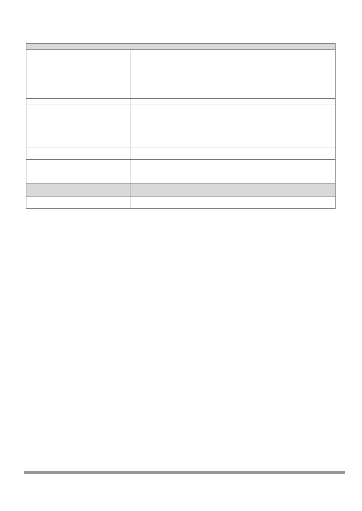
4. Technical Data
Basic Data
Mains power
SMARTCONTROL Standard: Power pack, 230 V AC to 24 V DC
IP65 variant: Integrated power pack, 100 to 240 V AC, 50 to 60 Hz, to 24 V DC
Power consumption
< 2.5 W (Actual power consumption depends upon power pack efficiency, as well as any other
connected sensors and devices.)
Control keys
Two function keys: F1 and reset in the housing
Operating conditions
5 to 50 °C, no condensation
Housing
SMARTCONTROL-Standard: Steel sheet metal, 226 x 210 x 70 mm (W x H x D) (special housing avail.)
IP65 variant: Steel sheet metal 380 x 380 x 210 mm (W x H x D)
Weight
SMARTCONTROL Standard: Approx. 1.5 kg
IP65 variant: Approx. 10 kg
Protection (IP 65 variant)
IP65 if installed correctly (applies to the non-lockable version only)
Analog Inputs
Up to 8 analog inputs
0 to 10 V voltage measurement or 0 to 20 mA current measurement, switchable (JP1 jumper series)
Internal resistor
Voltage measurement: 200 kOhm
Current measurement: 249 Ohm
Accuracy
Electrical Isolation
Common ground, no electrical isolation
Frequency
Max. recording rate: 1 per sec.
Suppressor diodes for voltage peaks
Yes
Relay Outputs
Up to 2 relay outputs
Up to 2 analog inputs can be reconfigured as relay outputs (jumper series JP6).
Relay type
1 each NO, 1 A, 40 V DC, PhotoMOS, no inductive loads
Temperature Inputs
Up to 8 temperature inputs per sensor type
Pt 1000 platinum temperature sensors with 2-wire connection
Measuring range
–50 to +170 °C
Accuracy
Better than ± 0.5 °C (depending on DIN class)
Suppressor diodes for voltage peaks
Yes
Frequency
Max. recording rate: 1 per sec.
Resolution
Better than 0.05 K
Digital Inputs
Up to 8 digital inputs
Either passive (e.g. reed contacts) or active pulse sources can be connected. Configurable via the (JP2
jumper series).
Passive reed contact load capacity
15 mA / typical input voltage: 12 or 24 V DC
Active signals
Min. 12 mA, max. 24 V, min. 12 V
Electrical isolation
Active operating mode: electrically isolated
Passive operating mode: not electrically isolated
Edge slope
Any
Filter (debouncing)
Digital (5 ms)
Pulse sequence
Min. 10 / 10 ms (0/1)
Frequency
Max. 50 Hz
Maximum recording rate
1 per second
Maximum cable length
200 m
Pulse inputs / status inputs
8, for example meters with pulse output or door contact as status input
Inputs which can be setup as tariff inputs
3 (IS1, IS3 and IS5), the respective upstream inputs (IS0, IS2, IS4) are counted.
Input can be used as a synchronizing input
1 (IS7), the clock is synchronized to the next quarter hour
Optical pulse display
LED on the PCB
typical ± 0.05 V
Page 9
9 GMC-I Messtechnik GmbH
Interfaces
RS 232 serial interface (MBUS/PRG)
Preferred protocol: M-Bus or uploading of firmware updates by means of field utility.
An M-Bus level converter with RS 232 interface is required in order to read out M-Bus compatible
devices in accordance with EN1434-3. Up to 250 devices can be addressed, baud rate can be set to
300, 2400 or 9600 baud, primary or secondary readout (selection).
Prerequisite: M-Bus protocol per EN1434-3, unlimited read-out interval (e.g. every 15 minutes),
devices preprogrammed at the factory with unique addresses.
RS 232 serial interface (FIELD 1)
Actuation of various fieldbus devices which are not equipped with an RS 485 interface.
FIELD 1 and the RS 485 interface are parallel wired.
RS 232 serial interface (FIELD 2)
Connector pin assignments upon request
Ethernet interface
Layout / parameters configuration of the SMARTCONTROL directly via TCP/IP at 10/100 MBit/s.
TCP/IP address via DHCP server or static. Interface for Modbus/TCP protocol (FW).
A public IP address is required for readout via the Internet, and port 2083 must be open or routed to
the SMARTCONTROL (firewall). Internet access must be set up with a flat rate (permanent
connection). Required hardware includes a DSL modem and a router. In the case of a non-static
public IP address, the router must support DynamicDNS service. Use of a VPN channel (virtual private
network) must be made available via separate hardware.
RS 485 interface
Fieldbus interface, distances of up to 1.2 km, connection of devices compatible with the ModBus or
ASCII protocol. Bus termination: internal, 220 Ohm, can be connected with jumper. Up to 32 devices.
Two RS 485/1 RS 485/2 interfaces
(SMARTCONTROL V3 only)
Fieldbus interface, distances of up to 1.2 km, connection of devices compatible with the ModBus or
ASCII protocol. Bus termination: internal, 110 Ohm, can be connected with jumper. Up to 250 devices.
FIELD 1 and the RS 485/1 interface are parallel wired.
FIELD 2 and the RS 485/2 interface are parallel wired.
Optional M-Bus Level Converter
(SMARTCONTROL V3 only)
M-Bus level converter, 80 socket module, article
no. Z301Y
1 slot for an M-Bus level converter module, up to standard loads
Page 10
10 GMC-I Messtechnik GmbH
5. Installation
5.1. Before Installing
Note:
Please check to make sure that the SMARTCONTROL and all included accessories are complete and
undamaged. The freight forwarder must be notified without delay in the event of transport
damage. The device may not be placed into operation in the event of damage.
5.1.1. Scope of Delivery for SMARTCONTROL Standard
The following is included in scope of delivery:
SMARTCONTROL
Installation instructions
Installation report
CD with SMARTCONTROL Manager software and documentation
RJ-45 crossover patch cable for connecting the SMARTCONTROL to a PC
The PC can also be connected by means of an additional module via analog modem, ISDN, GSM or Bluetooth. See
also section 8.2. , “Communication Modules”.
5.1.2. Scope of Delivery for SMARTCONTROL IP-65
The SMARTCONTROL is delivered in a control cabinet which fulfills IP 65 requirements (optionally lockable, lock
meets IP 34). The SMARTCONTROL consists of a single PCB system, a power pack, a circuit breaker and various
attachable components. In addition to this, optional devices (e.g. M-Bus, fieldbus) can be secured to the
integrated mounting rail or inserted into available slots on the PCB (e.g. socket modules or memory expansions).
Heavy duty cable glands (1 ea. M25, 4 ea. M16) are provided at the bottom for cable entry. The control cabinet is
available in other sizes upon request.
5.2. Operating conditions
Tip:
Carefully select the location at which the SMARTCONTROL will be installed. Don’t forget that a
230 V AC mains connection is required for operation of the SMARTCONTROL and, if applicable, that
communication facilities must be provided for remote read-out.
Recommended installation height: at least 50 cm, and not more than 150 cm from the floor to the
bottom edge of the cabinet or housing. The wall to which the device is mounted must be flat, dry and
sturdy.
Furthermore, the location of sensors, transducers and other devices which will be connected to the
SMARTCONTROL must also be taken into consideration in order to minimize wiring expenses.
Page 11

11 GMC-I Messtechnik GmbH
Note:
Close proximity to water, sources of heat, direct sunlight, radiators, devices which generate
electromagnetic fields, transmitters, high frequency sources, radiation emitting devices and
locations which are exposed to excessive vibration or shock must be avoided.
Ambient temperature should lie within a range of +5 and +50°C, and no condensation is allowed.
If these requirements are not fulfilled by the ambient conditions, please install fully encapsulated
devices only.
Note:
When recording energy data, make sure that the SMARTCONTROL is protected against
manipulation and destruction.
The devices are not intended for use in explosion-proof zones.
Observe additional information included section 3. , “General Safety Precautions” and section 4. , “Technical
Data”.
5.3. Wall Mounting
Warning:
Before drilling holes, make sure that there are no cables, pipes or other lines which have been
laid inside the wall in close proximity to the intended installation position.
5.3.1. Wall Mounting the SMARTCONTROL Standard
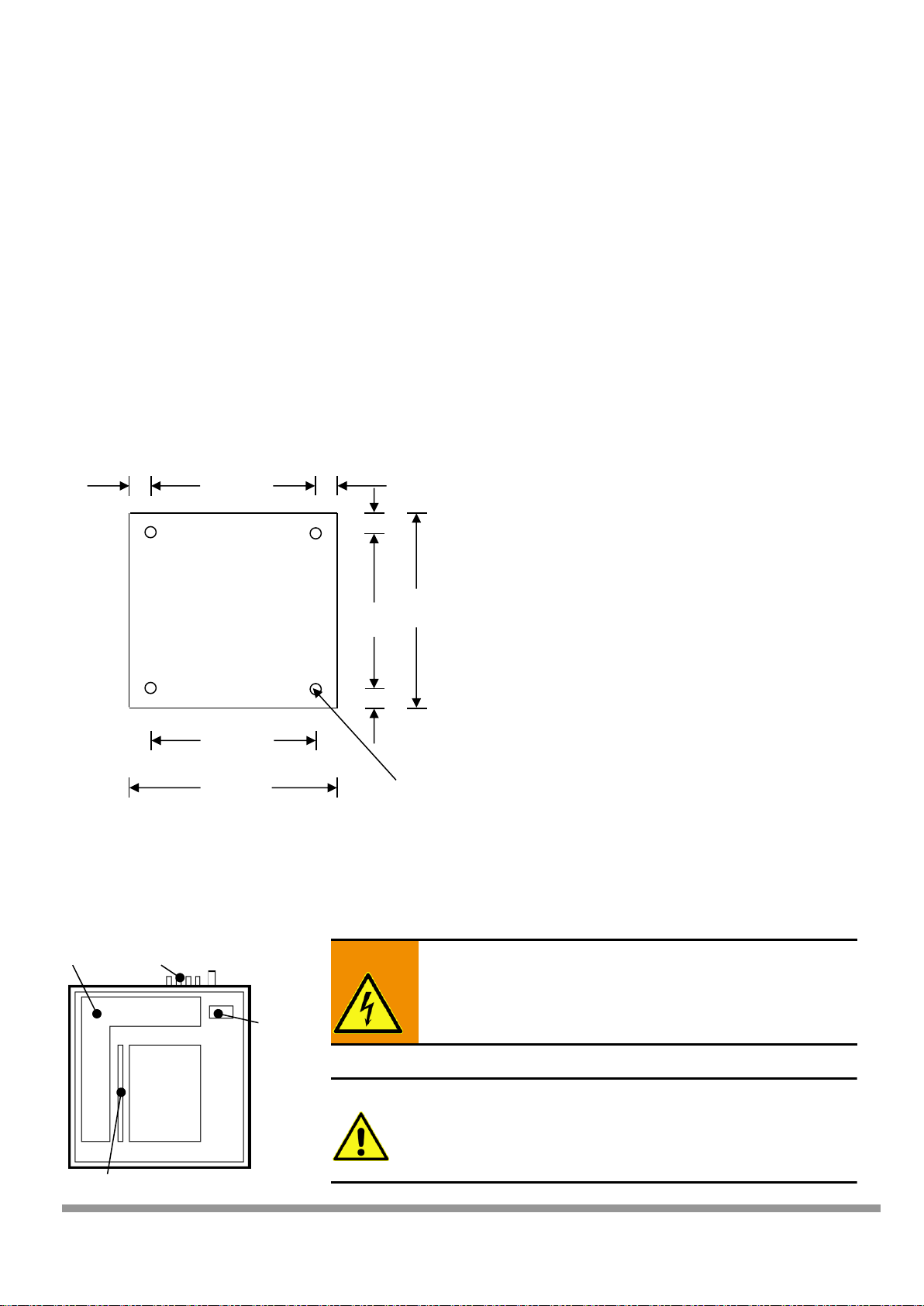
The housing has the following dimensions: approx. 226 x 210 x 70 mm (W x H x D).
The 3 holes in the housing are used to mount the SMARTCONTROL. Remove the 2 housing screws at the bottom
and open the housing cover in order to expose the mounting holes.
The top mounting hole is laid out as a slot, and the thickness of the housing wall is approximately 1 mm. The
SMARTCONTROL Standard is shipped with 4 installed housing screws. Only the two screws at the bottom need to
be loosened for mounting, because the opening in the housing top is only intended for the fiber-optic cable. The
top screws may not be loosened for this reason.
22.6 cm
16 cm
21 cm
The box must be securely
mounted with 3 suitable
screws and anchors, depending
upon substrate and material.
Housing Rear Panel
11.3 cm
11.3 cm
16 cm
Box mounting tab diameter:
approx. 5 mm
3.3 cm
3.3 cm
2.6 cm
Top Housing Screw
Top Housing Screw
Bottom
Housing
Screw
Page 12
12 GMC-I Messtechnik GmbH
The housing top can be tipped up after removing the two bottom screws with the included tool (stiff wire,
approx. 25 cm long) in order to work on the installed SMARTCONTROL.
Remove the bottom two screws and tip up the housing top to this end. Now insert one end of the tool into the
threaded drill hole for the bottom housing screw in the SMARTCONTROL base plate at either side of the
SMARTCONTROL – from the outside.
Insert the other end of the tool into the drill hole for the bottom screw in the housing top after it has been tipped
up.
5.3.2. Wall Mounting the IP 65 SMARTCONTROL
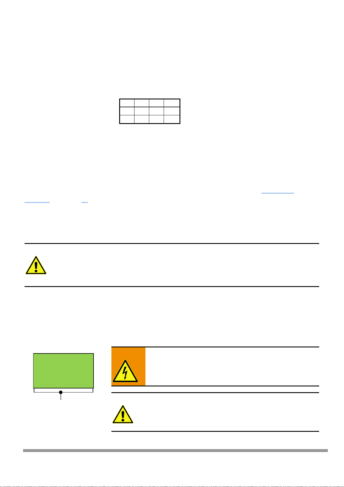
The standard version of the IP 65 housing has the following dimensions: approx. 380 x 380 x 210 mm (W x H x D).
The 4 holes in the housing are used to mount the SMARTCONTROL. Remove the right-hand cable duct cover in
order to expose all four mounting holes.
In the case of special orders, please check the dimensions of the IP 65 housing.
5.4. Power Supply Cable for the SMARTCONTROL IP 65
Warning:
Cables must be voltage-free.
Note:
The cables must be led in from the top and are secured by
means of heavy duty cable glands.
It must be assured that the cables are long enough to reach
the connector terminals.
38 cm
34 cm
34 cm
38 cm
The box must be securely
mounted with 4 suitable
screws and anchors,
depending upon substrate and
material.
Box Mounting Hole
Diameter:
Approx. 8.2 mm
2 cm
2 cm
Housing
Rear Panel
2 cm
2 cm
Terminal
Block
Heavy-Duty Cable Gland
Cable Duct
Ground Bus Bar
Page 13
13 GMC-I Messtechnik GmbH
SMARTCONTROL
5.5. SMARTCONTROL IP 65 Power Supply
The power supply cable may have no more than 3 conductors with a maximum cross-section of 4 square mm
each, and must be led in through the heavy duty cable gland at the bottom of the housing. This cable must be
connected to the 230 V AC terminal block (see below): N, PE and L1.
PE N F1
L1
Greenyellow
Blue
Brownblack
230 V AC supply power is fed via a circuit breaker (B6A) to the power pack (F1).
The SMARTCONTROL can be supplied with 12/24 V DC. The power pack is supplied with a standard output of
24 V DC, or with 12 V DC as an option. It’s also possible to install both power packs. If applicable, 24 V DC is
required for additional components such as an M-Bus level converter, and 12 V DC is required for certain sensors.
The SMARTCONTROL PCB is supplied with electrical power via the connector terminal [see “Connections
Overview,” in section 6. as of item 20].
5.6. Low-Current Leads
5.6.1. SMARTCONTROL IP 65
The leads are fed through the heavy duty cable glands at the bottom of the housing.
Note:
Tighten the threaded cable glands to the specified tightening torque. The housing must be waterproof. If necessary, the included connectors must be replaced with more suitable ones, and
unused connectors must be replaced with blanking plugs. It must be assured that only
standardized materials which are suitable for the IP 65 standard and which seal the openings
appropriately are utilized.
The shields of all shielded cables must be connected to a ground bus bar by means of shield terminals assuring
large surface-area connection. Identify all cables which are fed into the housing with the respective cable number
in accordance with the wiring diagram in a readily legible fashion using cable ties. Secure the cables firmly, with
cable ties if necessary.
5.6.2. SMARTCONTROL Standard
Warning:
Cables must be voltage-free.
Note:
The cables must be led in from the bottom and secured by
means of heavy duty cable glands.
It must be assured that the cables are long enough to reach the
connector terminals.
Ground Bus Bar
Page 14

14 GMC-I Messtechnik GmbH
5.6.3. All Types of SMARTCONTROL After Mounting
Tip:
See the “Connections Overview,” in section 6. and other instructions in this manual regarding
connection options.
Note:
► Retighten all screws and fasteners after installation has been completed.
► Green connector plugs for the various inputs (analog, temperature, digital) are located on
the PCB. Wires with cross-sections of up to 1.5 square mm can be connected.
Warning:
► Insulation testing must be executed in accordance with VDE. Do not expose components
which are not voltage-proof to high voltages during testing.
Page 15

15 GMC-I Messtechnik GmbH
6. Connections Overview, Revisions 2.xx
(1)
8 digital inputs: pulse/status/tariff
(14)
Key: F1
(2)
JP2: digital inputs (active/passive signal)
(15)
Key: reset
(3)
8 temperature inputs: Pt 1000
(16)
Option: compact flash card
(4)
6 analog inputs + 2 relay outputs / analog inputs
(17)
Expansion port
(5)
JP1: 0 to 10 V or 10 to 20 mA analog inputs
(18)
Battery for real-time clock (RTC)
(6)
JP6: A6/A7 as analog input or as K1/K2 relay outputs
(19)
LED: DIAG/COM
(7)
M-Bus via level converter / RS 232 programming
(20)
12 to 24 V DC supply power input
(8)
System jumper
(21)
12 to 24 V DC auxiliary power output
(9)
Interface: FIELD1 (RS 232), parallel to (12)
(22)
Connection: analog cable / ISDN cable
(10)
Interface: FIELD2 (RS 232)
(23)
JP5: selection of analog/ISDN
(11)
Interface: RJ45 Ethernet (10/100MBit), TCP/IP
(24)
JP3: adjust voltage at socket module
(12)
Interface: fieldbus (RS 485)
(25)
Module socket for analog/ISDN/GSM/Bluetooth
(13)
JP4: RS 485 termination
1 2 3
4
5
6 7 8
9
10
12
13
11
14
15
16
17
18
19
21
20
22
23
24
25
Page 16

16 GMC-I Messtechnik GmbH
6a. Connections Overview, Revision V3
(1)
8 digital inputs: pulse/status/tariff
(14)
Key: F1
(2)
JP2: digital inputs (active/passive signal)
(15)
Key: reset
(3)
8 temperature inputs: Pt 1000
(16)
microSD card slot
(4)
6 analog inputs + 2 relay outputs / analog inputs
(17)
Expansion port
(5)
JP1: 0 to 10 V or 10 to 20 mA analog inputs
(18)
Battery for real-time clock (RTC)
(6)
JP6: A6/A7 as analog input or as K1/K2 relay outputs
(19)
LED: DIAG/COM
(7)
M-Bus via level converter / RS 232 programming
(20)
12 to 24 V DC supply power input
(8)
System jumper
(21)
12 to 24 V DC auxiliary power output
(9)
Terminal strip (M-BUS,RS 485/2, Field1)
(22)
Connection: analog cable / ISDN cable
(10)
Interface: FIELD2 (RS232), parallel to (9) RS485/2
(23)
JP5: selection of analog/ISDN
(11)
Interface: RJ45 Ethernet (10/100MBit), TCP/IP
(24)
JP3: adjust voltage at socket module
(12)
Interface: RS485/1 parallel to (9) FIELD1
(25)
Module socket for analog/ISDN/GSM/Bluetooth
(13)
JP4: RS 485/1 termination
(26)
Card slot for M-Bus module (optional)
(27)
SV14: M-Bus port selector (MBUS/Field2)
(28)
JP7: RS 485/2 termination
(29)
Slot for fuse, M-Bus module (250 mAT)
(30)
SV23: GSM LED selection
(31)
RS 485/1 receive enable/disable
(32)
RS 485/2 receive enable/disable
(33)
LED display, M-Bus module (collision/RX/Tx)
(34)
COP (reserved)
1
2 3 4
5 6 7 8 8 9 10
11
12
13
14
15
16
17
19
18
20
21
22
23
24
25
26
27
28
29
30
32
31
33
34
Page 17

17 GMC-I Messtechnik GmbH
Connections Overview, Revision V3
Jumper Layout (defaults)
Terminal Strip Pin Assignments (9)
M-Bus mains connection
MBUS+
MBUS-
System ground
GND
RS 485/2 interface connection
A (data+)
B (data-)
System ground
GND
FIELD1 (RS 232) interface connection
Rx
Tx
M-Bus Port Selector SV14 (27)
These two jumpers can be used to select via which interface the optional M-Bus module will communicate. Either
M-Bus (7) or FIELD2 (10) can be selected.
SV14, selection of M-Bus interface (7) SV14, selection of FIELD2 interface (10)
Page 18

18 GMC-I Messtechnik GmbH
7. Inputs/Outputs
7.1. Note Regarding All Measuring Channels
Note:
The following points must be observed in order to achieve high measuring accuracy:
Use shielded cables only. If possible, connect the shield to a separate ground contact
(available as a shield bus with the SMARTCONTROL/IP65).
Large cable diameters, at least 0.6 mm (recommended: 0.8 mm, max. 1.5 mm)
Keep cables as short as possible.
Ferrite beads attached to both cable ends
Do not lay cables parallel to heavy current conductors!
7.2. Analog Inputs (current/voltage)
The connector plugs are designated, and must be connected, as shown below (polarity as specified):
+ = Measuring signal
- = All eight inputs have a common ground
which also functions as the negative terminal.
They are not electrically isolated.
7.2.1. Selecting Relay Outputs / Analog Inputs
The 6 analog inputs, A0 through A5 (terminals 1 through 12), are intended for the connection of measuring
transducers (e.g. pressure sensor, atmospheric humidity sensor etc.) with 0 to 10 V or 0 to 20 mA output signals.
Terminals 13 through 16 can be used either as relay outputs K1 and K2 or analog inputs A6 and A7. Jumper series
JP6 determines whether a relay output or an analog input will be used. The relay output mode is the default
value.
Series 1+2: A6/K1
Series 3+4: A7/K2
7.2.2. Setting Analog Inputs to Current/Voltage Measurement
Voltage or current measurement is selected with jumper series JP1. These jumpers are assigned to the respective
analog input (from left to right: A0 to A7), and are set to the voltage measurement operating mode (0 to 10 V) at
the factory. In order to measure a current signal (0 to 20 mA), the blue jumper which corresponds to the analog
input must be inserted as follows:
This example shows a voltage measurement at A0-A3 and
A5. A4 us used as a current measuring input. With this layout
for the JP6 series, A6 and A7 are relay outputs K1 and K2.
Internal resistance for voltage measurement: 200 kOhm, for current measurement: 249 Ohm
Page 19

19 GMC-I Messtechnik GmbH
Note:
If an input is used for 0/4 to 20 mA measurement, reconfigure the corresponding input with
SMARTCONTROL Manager software. The default setting is the voltage measurement mode in this
case as well [see details in section on SMARTCONTROL Manager, AD converter].
7.3. Temperature Inputs
The 8 temperature inputs, T0 through T7 (terminals 17 through 32) are used to record temperatures. Only Pt1000
sensors with 2-wire connection may be used. The measuring range is -50 to +170 °C.
Tip:
If greater accuracy is required, class 1/3 B sensors can be used.
The connector plugs are designated, and must be connected, as shown below (polarity is arbitrary):
Note:
Cable length and wire cross-section have a significant influence on measuring accuracy. Connect
each sensor separately with two wires each. Ground the sensor cable shield at one end to the
SMARTCONTROL housing.
► An offset can be additionally entered to compensate for deviations by means of software
[see temperature inputs in SMARTCONTROL Manager manual].
► Avoid cable lengths of greater than 20 meters, because the temperature coefficient of the
laid copper cable is otherwise no longer negligible.
7.4. Digital Inputs (pulse / status / tariff / time synchronization)
The 8 digital inputs, IS0 through IS7 (terminals 33 through 48) are intended for use as meter or status inputs
(current, gas and water meters, door and window contacts etc.). Input S7 can also be used for time
synchronization.
7.4.1. Setting the Operating Mode (passive/active) of the Digital Input
Pulse generators / status signals with their own power supply (active, with electrical isolation) or pulse generators /
status signals with open collector / floating contact output (passive, no electrical isolation, e.g. reed) can be
connected.
The signal type or operating mode is set with jumper series JP2, which determines electrical configuration. These
jumpers (red jumpers included in scope of delivery) are assigned to the respective digital inputs (from left to right:
IS0 to IS7), and are set to the passive operating mode at the factory.
Page 20

20 GMC-I Messtechnik GmbH
This example shows the configuration for 6 passive
digital inputs (S0, S1, S3 and S5-S7) and 2 active inputs
(S2 and S4).
Warning:
Polarity is determined by the jumper setting.
Polarity must be correct!
“Active” jumper setting
“Passive” jumper setting
Terminal a = pulse input / status +
Terminal b = pulse input / status –
Terminal a = contact - / GND
Terminal b = contact + / open collector
Connection of, for example, pulse generators with
their own 12 to 24 V power supply / output signal
with load capacity of at least 15 mA
Connection of, for example, pulse generators with
reed contact and a minimum contact / open collector
load capacity of 15m A
** Electrical isolation **
GND connected to each other
** No electrical isolation **
Sample terminal assignments (S2 and S4 active , rest
passive):
S0a GND, S0b + (as well as S1, S3, S5-S7)
S2a +, S2b – (as well as S4)
7.4.2. Configuring the Digital Inputs
If a digital input is used as a status input (e.g. door contact, burner on-time etc.), a status command must be set
up with SMARTCONTROL Manager software in order to assure that every change to the input signal is recorded
[see section entitled SMARTCONTROL Manager, Status Command Type].
These tariff and synchronizing inputs are configured with SMARTCONTROL Manager software (see the “Meters”
section in the SMARTCONTROL manual.
It’s also possible to record tariff data, for example peak tariff (HT) and off-peak tariff (NT). There are 3 tariff
inputs: IS1, IS3 and IS5.
A 0 or 1 signal applied there (floating relay, peak/off-peak tariff signal) specifies whether assigned inputs IS0, IS2
and IS4 will be counted as peak or off-peak tariff. For example, tariff input IS1 specifies whether pulses from IS0
will be allocated to HT or NT.
Page 21

21 GMC-I Messtechnik GmbH
7.5. Broken Cable Detection (Namur)
Broken cable detection (Namur) can be used for passive pulse sources.
7.5.1. Mode of Operation
The passive digital input records, for instance, meter data.
The analog input is configured in the SMARTCONTROL Manager as a 0 to 10 V voltage input. As soon as the
measured voltage falls below 0.2 V, this is indicated as a broken sensor.
Details regarding programming are included in the SMARTCONTROL Manager manual.
Note:
The alarm limit and the resistor values must be adapted to the system.
Long cables can only be used under certain circumstances with this circuit layout, and
must thus be carefully configured.
7.5.2. Connection Example
A SMARTCONTROL digital input, in this example 33/34, is set to the passive operating mode with the help of
jumpers. An analog input, in this example 1/2, is set to the voltage measuring mode for 0 to 10 V with the help of
jumpers.
A 15 kOhm resistor is installed at the pulse generator, and 1.5 and 1 kOhm resistors are installed at the
SMARTCONTROL.
Inputs
IS0
IS1
IS2
IS3
IS4
IS5
IS6
IS7
Pulse X X X X X X X X
Status
X X X X X X X X Tariff X X X
Synchronizing
X
Digital Inputs
Analog Inputs
Pulse Generator,
e.g. Meter
1.5 kOhm
Page 22

22 GMC-I Messtechnik GmbH
7.5.3. Connection Example 2 for Devices with Namur Output
A SMARTCONTROL digital input, in this example 33/34, is set to the passive operating mode with the help of
jumpers. An analog input, in this example 1/2, is set to the voltage measuring mode for 0 to 10 V with the help of
jumpers.
A 1 kOhm resistor is installed at the SMARTCONTROL. If a SMARTCONTROL with 12 V power pack is used, a
0.47 kOhm resistor must be installed.
Tip:
Due to the higher measuring voltage, a SMARTCONTROL with 24 V power pack is recommended.
Digital Inputs
Analog Inputs
Pulse Generator,
e.g. Meter
1 kOhm
(0.47 kOhm
for 12 V power pack)
Page 23

23 GMC-I Messtechnik GmbH
8. Communication
8.1. Protocols
Each SMARTCONTROL interface can use several protocols. Simultaneous use of several protocols at the same
interface is not possible. The interfaces’ functions are configured in the SMARTCONTROL Manager.
8.1.1. RS 232 / M-Bus
RS 232 / M-Bus is available at terminals (7), (9) and (10) [see section 6. , “Connections Overview,”] as a 9-pin DSub plug. M-Bus compatible devices can also be connected to these terminals.
Supported baud rates (RS 232 and M-Bus): 300, 2400, 9600 and 19,200 baud
Note:
The following conditions must be fulfilled in order to allow for use of M-Bus devices:
M-Bus level converter with RS 232 port or optionally available M-Bus level converter 80 socket
module (article no. Z301Y) for the Gossen Metrawatt SMARTCONTROL V3.
Protocol: DIN EN 13757-3 (previously EN1434-3)
Unlimited readout interval (e.g. every 15 minutes)
M-Bus devices should be preprogrammed at the factory with unique addresses.
Maximum cable lengths for M-Bus networks must also be adhered to.
M-Bus level converters are available for 3, 20, 30, 60 or 250 devices. Up to 480 M-Bus devices can be addressed
by the SMARTCONTROL via M-Bus repeaters. However, we recommend limiting the size of M-Bus networks to
250 devices per SMARTCONTROL (interference, management, operating reliability).
8.1.2. M-Bus Routing Function
With the help of MR firmware, the SMARTCONTROL can function as a router within an existing M-Bus network
[see section 9.1. , “Firmware Options”]. This is necessary in the event that the read-out intervals of the previous
installation are inadequate for energy management.
Interfaces (7) M-Bus and (9) FIELD2 are used to this end [see section 6. , “Connections Overview,”]. The level
converter is connected to interface (7), and the building management system to interface (9).
Access to the M-Bus by the building management system remains intact – the building management system has
precedence.
8.1.3. RS 485 / Modbus RTU / Modbus TCP
RS 485 available at terminal (12) as 3-pole connection [see section 6. , “Connections Overview,”]. Firmware
option MO is required to this end [see section 9.1. , “Firmware Options”].
Supported baud rates (RS 232 and M-Bus): 1200, 2400, 4800, 9600 and 19,200 baud.
Modbus TCP is also supported. Terminal (11) is used to this end.
Page 24

24 GMC-I Messtechnik GmbH
Note:
Interfaces (9) FIELD1 and (12) RS 485 (RS 485/1 for V3) are wired in parallel [see section
6. , “Connections Overview,”]. Using different protocols at the same time may result in errors
and bus interference.
The assignment for terminal (12) is printed in the SMARTCONTROL housing as A through C, and the conductors
are identified as 1 through 3 at the plug. A/1 (+), B/2 (-), C/3 (equipotential bonding).
Warning:
The Mod-Bus specification defines power supply (A –, B +) differently than the RS 485
specification (A +, B –).
Before connecting, determine which specification applies to the device to be connected!
Note:
Do not use terminal C (data ground) if the modules are supplied with power from the
SMARTCONTROL! This terminal is used exclusively to compensate for extraneous voltages from
other devices. It is thus not suitable for supplying power to the devices!
SMARTCONTROL
Module with External
Power Supply
Module with Supply Power from the
SMARTCONTROL
A
Data +
Data +
B
Data –
Data –
C C ---
V +
---
V +
V -
---
V -
Topology: Under no circumstances may branches be laid with lengths of more than 2 meters.
Note:
Wiring is always looped through 1:1 from module to module.
The RS 485 bus has to be terminated at its ends with two resistors. In the case of short
distances (< 10 m), termination can be omitted. In the case of larger installations,
termination must be carefully executed: under no circumstances may bus voltage drop to
below 0.3 V. Under normal conditions, termination can be set up directly on the PCB with
the green JP4 jumper [see item (13) in section 6. , “Connections Overview,”] (220/110
Ohm). In special cases, lower resistance values are required (must be laid out correctly by
qualified personnel).
8.1.4. ASCII Fieldbus Modules
Fieldbus modules which communicate via the ASCII protocol can be connected to terminals (9) and (12) [see
section 6. , “Connections Overview,”]. Firmware with option AA is required to this end [see section 9.1. ,
“Firmware Options”].
Please note that the two interfaces are parallel connected.
Supported baud rates: 1200, 2400, 4800, 9600, 19,200, 38,400 and 57,600 baud.
Page 25

25 GMC-I Messtechnik GmbH
8.1.5. TCP/IP
The integrated Ethernet interface included as standard equipment works with the usual TCP/IP protocol at
10/100 MBit per second. The SMARTCONTROL can be read out, and its parameters can be configured, via this
interface. The TCP/IP address can either be retrieved from a DHCP server or statically assigned.
Tip:
A crossover cable is required when connecting the SMARTCONTROL directly to a PC (included with
the SMARTCONTROL).
Note:
Static addresses are absolutely essential for the creation of a SMARTCONTROL network with
several devices which are required to communicate with each other (data / measured value
exchange)!
A public IP address is required for readout via the Internet, and port 2083 (firewall) must be open
or routed to SMARTCONTROL.
Internet access must be set up with a flat rate (permanent connection). Required hardware
includes a DSL modem and a router.
In the case of a non-static public IP address, the router must support dynamic DNS service. As a
rule, DynDNS is available on the Internet free of charge.
Use of a VPN channel (virtual private network) must be made available via separate hardware.
8.1.6. Additional Protocols
The SMARTCONTROL is compatible with other protocols as well such as CLBus (IEC1107, IEC62056-21), LON (via
optional LON interface). Relevant information is available upon request.
Page 26

26 GMC-I Messtechnik GmbH
8.2. Communication Modules (no longer available)
Note:
Before beginning any work, disconnect the entire system from all sources of electrical power
Never insert a socket module when the system is switched on [refer to section 9.3. , “Shutting
Down and Restarting SMARTCONTROL”].
Electrostatic charging must be avoided.
Provide for electrostatic discharging of personnel and tools before beginning work.
Before inserting the module, make sure that the correct operating voltage has been selected for
the respective module.
Warning:
If the supply voltage setting is incorrect, the module may malfunction, or it
may be damaged.
Note:
Jumper JP5 [see item 23 in section 6. , “Connections Overview,”] is
used to configure the ISDN/PHONE-RJ45 connector jack to
analog/ISDN operation. Make sure that the jumper configuration is
correct before initial start-up. A jumper must be plugged onto both
JP5 pins identified analog/ISDN. The jumpers have to be removed
for GSM/GPRS or Bluetooth modules.
Module Type
Voltage to be Selected
Analog modem
3.3 V
ISDN
3.3 V
Bluetooth
3.3 V
GSM, 3.3 V version
3.3 V
GSM, 5 V version
5.0 V
PWR_MOD1/
Jumper JP3
8.2.1. Applicable to All Modules
The SMARTCONTROL’s communication interface can be adapted to your requirements via the socket slot (DIL64)
[see item 25 in section 6. , “Connections Overview,”]. These are optional and are not included with the
SMARTCONTROL. The following options are available: analog modem, ISDN, GSM/GPRS and Bluetooth.
The module’s operating voltage is determined by jumper series JP3, “PWR_MOD1”, at the left above the modem
slot [see item 25 in section 6. , “Connections Overview,”].
The default setting is 3.3 V for operation with analog modems and ISDN modules.
Otherwise, insert jumper JP3 such that the required operating voltage is selected.
Page 27

27 GMC-I Messtechnik GmbH
8.2.2. Module Installation
Unpack the new module and make sure that all of the pins are straight. The module is inserted into the socket
provided to this end [see item 25 in section 6. , “Connections Overview,”].
Tip:
If a previously inserted modules needs to be removed, pull it out carefully. Grip the module at the
left and right-hand sides with both hands underneath the PCB, and pull it out slowly and carefully.
The module must not be tilted during removal.
Jack A in the socket, identified with a white arrow, serves as a point of orientation on the PCB. The point of
orientation on the module is pin A.
Carefully insert the module. Pin A on the module must be inserted into jack A at the socket. Make sure that all of
the other pins are also inserted in to their corresponding jacks. (Depending upon the type of module, some of the
pins in the middle portion of the module might not be connected.)
Grasp the module at the sides of the PCB with both hands and push it into the socket carefully and evenly,
avoiding any tilting. Inspect the module to make sure that none of the pins have been bent.
8.2.3. Analog-Modem Module
The analog module is inserted at the factory as standard equipment. Please check the condition of the module.
See also section 8.2.1. , “Applicable to All Modules”.
For SMARTCONTROL IP 65: Feed the RJ11 plug at the end of the modem’s connector cable into the box via one of
the cable glands. Lay the cable into the cable duct in the box.
For all SMARTCONTROL versions: Insert the RJ11 plug on the connector cable into the ISDN/PHONE-RJ45 jack for
analog connection on the PCB [see item 22 in section 6. , “Connections Overview,”]
Plug the other end of the cable into a TAE-N telephone socket.
A reset must then be executed in order to assure that the new setting is transferred to the modem (refer to
section 9.3. , “Shutting Down and Restarting SMARTCONTROL”).
After restarting, make sure that the communication LEDs between the RJ45 jack and the modem blink briefly
several times.
Note:
An analog connection must be available at the SMARTCONTROL. Operation at analog
private branch extensions is possible.
The number of rings before the modem answers a call can be selected with the
SMARTCONTROL Manager. At least 1 must be entered. If no setting is entered, or if the
number of rings is set to 0, the analog modem does not answer at all!
The connection is laid out as an RJ45 jack. Use an RJ11 cable to connect the analog modem!
Socket module from above, pin A
Jack A identified with a
white arrow on the PCB
Page 28

28 GMC-I Messtechnik GmbH
8.2.4. ISDN Module
The ISDN module is inserted at the factory as standard equipment. Please check the condition of the module. See
also section 8.2.1. , “Applicable to All Modules”.
Note:
The prerequisite for operation with this module is an RJ45 ISDN connection socket on an
external/internal ISDN S0 bus.
An unused digital number must be available.
If no number is programmed, the module answers all incoming digital calls (X.75 protocol
only).
Wiring of the ISDN connection must comply with ISDN specifications. These include:
terminating resistor in the last TAE socket, maximum cable lengths depending on
installation cable and number of devices to be connected.
For SMARTCONTROL IP 65: Feed the RJ45 plug at the end of the connector cable to the module via one of the
cable glands. Lay the cable into the cable duct in the box.
For all SMARTCONTROL versions: Insert the connector cable plug into the connector jack for ISDN connection
(RJ45) on the PCB [see item 22 in section 6. , “Connections Overview,”].
Plug the other end of the cable into an ISDN telephone socket (RJ45).
If applicable, use an ISDN tester in order to check your ISDN connection.
8.2.5. Bluetooth Module
The Bluetooth module is inserted at the factory as standard equipment. Please check the condition of the module
and make sure that module accessories are complete (module, adapter cable including cable gland, antenna). See
also section 8.2.1. , “Applicable to All Modules”.
Note:
Never operate the SMARTCONTROL without an antenna if a Bluetooth modem has been
installed!
The prerequisite for establishing connections with this module is a Bluetooth compatible
PC or notebook.
Positioning of the antenna has a significant influence on signal quality.
The Bluetooth module has a limited transmission range (class 1: 100 meters with
unobstructed view). The Bluetooth compatible PC or notebook must also comply with
class 1 (i.e. 100 m range). Walls, windows and doors reduce transmission range
considerably.
Enter a password in the SMARTCONTROL Manager. This increases security for the
prevention of unauthorized data access and changes to the SMARTCONTROL
configuration. Although serial connections can still be established, no other commands
can then be executed in SMARTCONTROL.
An antenna must be installed in addition to the Bluetooth module. The antenna is used to establish connections
to Bluetooth compatible devices. The included antenna (cable length of approx. 300 cm) is connected to the FME
plug (adapter cable) by means of the FME socket.
Page 29

29 GMC-I Messtechnik GmbH
The included adapter cable (approx. 25 cm) connects the module to the antenna. The adapter cable is furnished
with an MMCX/FME mounting plug. The MMCX plug is connected to the module. The FME plug serves to connect
the antenna, and is used as a housing feed-through at the same time. A drill hole with a diameter of 11 mm is
required for the SMARTCONTROL IP 65 to this end.
Connection is established from the Bluetooth compatible PC or notebook to SMARTCONTROL via a “virtual COM
port” [see “SMARTCONTROL Quick Start”].
As a rule, connection and disconnection are automatic when an application initializes the serial port. Experience
has shown that with some drivers the Bluetooth software assigns various COM ports.
Tip:
If you’re using a laptop with integrated Bluetooth adapter, deactivate the adapter and use our
class 1 USB sticks.
The Bluetooth serial connection is now ready to communicate with SMARTCONTROL. You won’t need to make
any further settings in the future.
8.2.6. GSM/GPRS Module
Warning:
A valid PIN must be entered with the help of the SMARTCONTROL Manager before installation
and initial start-up [see the section concerning modems in the SMARTCONTROL Manager
manual]!
If an incorrect PIN is entered, or none at all, the SIM card is disabled automatically after
initialization has been attempted three times!
For this reason, the GSM module is not inserted at the factory as standard equipment. Please check the condition
of the module and make sure that module accessories are complete (module, adapter cable including cable gland,
antenna).
Note:
Never operate the SMARTCONTROL without an antenna if a GSM module is used!
The prerequisites for operation with this module include a contract with a network service
provider and an enabled SIM card.
An antenna must be installed in addition to the GSM module. This antenna is used to
establish contact with the network service provider.
The installation site must also be checked for good reception.
► If applicable, remove the jumper plugged onto JP5 [see item 23 in section 6. , “Connections Overview,”].
► The SIM card furnished by the network service provider must be inserted into the GSM module before the
module is installed. The module is then installed to the available socket.
► Check the specified operating voltage for the GSM module.
Page 30

30 GMC-I Messtechnik GmbH
The included adapter cable (approx. 50 cm) connects the module to the antenna. The adapter cable is furnished
with an MMS/FME mounting plug. The MMS plug is connected to the module. The FME plug serves to connect
the antenna, and is used as a housing feed-through at the same time. A drill hole with a diameter of 11 mm is
required to this end (SMARTCONTROL IP 65 only). Please refer to the included data sheet for precise technical
details.
The included antenna (cable length of approx. 300 cm) is connected to the FME plug (adapter cable) by means of
the FME socket. Please refer to the included data sheet for precise technical details.
Tip:
Positioning of the antenna has a significant influence reception quality. The following
points must be observed in order to assure good reception:
Install the antenna in close proximity to openings to the outdoor environment.
If possible, install the antenna above the highest point of local terrain.
Install the antenna above components which might function as a shield, e.g. reinforced
concrete ceilings.
Amongst other things, a booster is required for longer cables (> 20 m).
Receiving signal strength is indicated in the SMARTCONTROL Manager under Extras -> Receiving signal strength.
This function is included as a standard feature as of SMARTCONTROL firmware version 2.2.00.
In the case of TCP/IP connection, receiving signal strength is refreshed each time – only the last value is shown for
modem connections. Receiving signal strength is refreshed every 3 second during operation, and is saved as “User
action type 316”.
Page 31

31 GMC-I Messtechnik GmbH
9. Initial Start-Up / Configuration
9.1. Firmware Options
Determine whether or not the right firmware has been installed to the SMARTCONTROL for the functions you
require. Various function modules can be integrated into the firmware (SMARTCONTROL “operating system”)
depending upon the task at hand. Some functions have to be enabled with a license. Others have to be installed
by loading additional firmware.
Firmware can be uploaded via the SMARTCONTROL Manager. The upload function is accessed via the main menu
~Extras ~Firmware upload... After selecting the file, the firmware is installed and the SMARTCONTROL is then
restarted.
Tip:
The additional modules included with the SMARTCONTROL are displayed in the “Options” field on
the Configuration -> Info tab in the SMARTCONTROL Manager with the help of abbreviations.
Online help for the individual firmware options can be accessed by clicking the “?” button next to
the “Options” field.
Standard Firmware
MA
M-Bus analyzer
MB
M-Bus function
HX
HX calculation – calculation of state of humid air (psychrometrics)
Firmware can be enabled with a license for the standard version
AA
Fieldbus, ASCII format, read only – included in RS 485 acquisition package
CN
Modbus RTU/TCP + fieldbus, ASCII format - included in controller package
MO
Included in RS 485 acquisition package
- Modbus RTU/TCP, read only
PI
Included in controller package – PID controller
PS
Peak load single / peak load optimization – for simple systems or individual devices
Note:
New functions are also implemented via the firmware.
A firmware update must be executed in order to be able to use these new functions.
Page 32

32 GMC-I Messtechnik GmbH
Firmware for Extended Functionality
CL
CLBus (IEC1107, IEC62056-21)
LO
LON
MP
Network modem - serial modem port over TCP/IP
A modem module integrated in to the SMARTCONTROL is made accessible with this
firmware via TCP/IP network
MR
M-Bus router function – transforms the SMARTCONTROL into an M-Bus router
The SMARTCONTROL is installed between, for example, GLT and M-Bus level
converters.
Two RS 232 ports at the SMARTCONTROL are used for incoming and outgoing lines.
Allows for read-out and remote querying of the M-Bus.
Access to the M-Bus by the building management system remains intact – the
building management system has precedence.
MS
SB as Modbus RTU slave / TCP slave
A Modbus master can pick up or received data within the SB
Functions AA and MO are no longer available.
SD
Support for SD cards. An additional adapter is required in this case. As of
SMARTCONTROL V3, the slot for the memory card is directly on the PCB.
9.2. Initial Start-Up
9.2.1. DIAG / COM LEDs
Make sure that all cables (power supply, data channels, communication lines) are connected and, in the case of
SMARTCONTROL standard, that the housing cover is closed and secured with the screw.
After the circuit breaker (SC/IP65) is switched on or the power pack (SC/Standard) is plugged in, the DIAG LED [see
item 19 in section 6. , “Connections Overview,”] must blink for about 5 seconds after initialization.
Page 33

33 GMC-I Messtechnik GmbH
9.2.2. Status Display / Error Diagnosis – DIAG LED
DIAG LED description: Brief blinking: . (dot), long blink: - (dash)
Pause: short pause: _ , long pause: __ (underline)
Mode
Pattern
Description
Normal operation:
- _ - _ - _ -
Long blink, short pause
General error:
. . . . . . . . .
Fast, short blinking
Onboard flash (2 MB) defective:
.- __ .-__ .-
Short, long and long pause
Compact flash error:
.. __ .. __ ..
Short, short and long pause
Password deleted:
-. __ -. __
Long, short, long pause
Deleting flash memory:
................
Very short blinking (flickering)
Maintenance mode (as of firmware version
1.1.34):
._.__._. __._.
Short blink, short pause, short blink and long
pause
9.3. Shutting Down and Restarting SMARTCONTROL
Approximately once every 15 minutes, SMARTCONTROL transfers recorded data from volatile RAM to non-volatile
flash memory.
Data stored in RAM which have not yet been written to flash memory are lost in the event of a restart.
A maintenance mode is provided as of firmware version 1.1.34, allowing for immediate saving of data before a
restart. After pressing and holding the F1 key [see item 14 in section 6. , “Connections Overview,”] for 5 seconds,
data are written from RAM to non-volatile flash memory.
The blinking pattern at the DIAG LED changes. The SMARTCONTROL can now be shut down or restarted by
pressing the reset key [see item 15 in section 6. , “Connections Overview,”]. If no further action is taken after
pressing the F1 key, the SMARTCONTROL resumes normal operation after 60 seconds.
Tip:
Information regarding the current firmware version can be displayed in the SMARTCONTROL
Manager by accessing “Info” in the “Configuration” tab.
9.4. Configuration
Note:
In order to start data recording, the SMARTCONTROL must be configured with SMARTCONTROL
Manager software.
SMARTCONTROL must therefore be connected to the PC for initial configuration. This connection
can be established by means of the Ethernet port or one of the socket modem options.
Page 34

34 GMC-I Messtechnik GmbH
9.4.1. Configuration via the Ethernet Port
A crossover patch cable must be used for direct connection of the SMARTCONTROL to the PC (included with the
SMARTCONTROL).
Each SMARTCONTROL has the following static IP address as a default setting: 192.168.130.190. There are two
possibilities for data exchange:
Either IP address 192.168.130.XXX and subnet mask 255.255.255.0 are selected at the PC or notebook (XXX being
a number between 1 and 254 but not 190).
The TCP/IP address at the SMARTCONTROL is changed (possible without changing the PC’s IP).
The procedure is described in detail in the SMARTCONTROL Manager manual beginning with the section entitled
“Setting Up Projects, Buildings and SMARTCONTROLs”.
9.4.2. Configuration via Analog Modem or ISDN
A PC with an analog modem or an ISDN adapter with corresponding telephone line must be used.
Please note: The ISDN module in the SMARTCONTROL cannot be queried by an analog modem without additional
hardware.
Start Gossen Metrawatt “SMARTCONTROL Manager” software, and then establish connection and configure the
SMARTCONTROL as described in the manual beginning with the section entitled “Setting Up Projects, Buildings
and SMARTCONTROL”].
9.4.3. Deleting the Password
a) Press and hold the F1 key [see item 14 in section 6. , “Connections Overview,”].
b) Briefly press the reset key [see item 15 in section 6. , “Connections Overview,”].
c) Release the F1 key.
d) Wait until the DIAG LED goes out [see item 19 in section 6. , “Connections Overview,”].
e) Press and hold the F1 key (max. 5 seconds) until the DIAG LED starts blinking.
Page 35

35 GMC-I Messtechnik GmbH
10. Options
The SMARTCONTROL allows for connection of many other optionally available modules (not included in the scope
of delivery). Additional firmware / an additional firmware license is necessary in some cases [see section 9.1. ,
“Firmware Options”].
10.1. Relay Outputs
In addition to the 2 onboard relays, additional relay outputs can be implemented via RS 485 fieldbus modules. For
connection and programming see the section in the SMARTCONTROL Manager entitled “Fieldbus Modules at the
RS 485 Port”.
A firmware license is available for controlling the modules (RS 485 acquisition package, article no. Nr.00730 or
RS 485 controller package, article no. 00731).
10.2. I/O Modules
Numerous other modules are also available (e.g. analog I/O, digital I/O). Please refer to the manual for the
respective module regarding connection.
10.3. Compact Flash Card (support discontinued and replaced by microSD card)
Gossen Metrawatt’s SMARTCONTROL is equipped with internal flash memory with 2 MBytes of capacity as a
standard feature, to which data are saved.
Internal memory can be expanded with the compact flash card, e.g. for:
Large networks
Short readout cycle for M-Bus meters
Infrequent or no data transmission
Double data backup
Automatic backup of current configuration and programming
The SMARTCONTROL can address cards with capacities of up to 2 GB.
Note:
We cannot guarantee that CF cards which have not been purchased from us will function with the
SMARTCONTROL. The SMARTCONTROL only detects and reads cards which support the “true IDE
mode”.
Cards purchased from us have been tested for use with the SMARTCONTROL, and are formatted
before shipment.
Pre-configuration is executed by mean of SMARTCONTROL Manager software (refer to the section entitled
“SMARTCONTROL Manager” for further details), and by means of hardware with a compact card reader which has
been connected to the PC.
The preconfigured card is inserted into the flash card slot [see item 16 in section 6. , “Connections Overview,”]
with the contacts facing the PCB.
Page 36

36 GMC-I Messtechnik GmbH
Note:
Refer to the section
9.3. , “Shutting Down and Restarting SMARTCONTROL”, regarding how to save data recorded to
RAM.
After the card has been inserted, SMARTCONTROL must be restarted by pressing the reset key [see item 15 in
section 6. ,“Connections Overview,”].
The flash card is then automatically detected by the SMARTCONTROL, and data is stored to it parallel to internal
flash memory. The compact flash card is also organized as a ring buffer.
The current user program is also saved to the compact flash card each time SMARTCONTROL is started and each
time reprogramming takes place. This is required for subsequent read-out of the card at a PC.
10.3.1 Using the microSD Card in SMARTCONTROL Rev2.xx and Rev.V3
microSD cards are supported as of version 2.4.03a. In order to use a microSD card, firmware version 2.xx with
option “SD” must be loaded to the SMARTCONTROL PCB, and an adapter is required as well. As of
SMARTCONTROL version V3, only microSD cards are used as a data storage medium. The adapter is no longer
necessary in this case, because the microSD slot (16) is installed directly to the PCB. The microSD card provides
the same scope of functions as was also the case with the compact flash card.
10.4. Backing Up Configuration and Program to a Compact Flash Card
As of firmware version 2.0.15, the configuration and the program are automatically backed up to the installed
CF card.
Please note that complete and correct configuration data must be available from the CF card in order to restore
them successfully.
The following actions trigger storage of the configuration data to the CF card:
Each time configuration data are written
Each time a program is started
Each time the system is started
A backup can be uploaded to a new SMARTCONTROL as follows:
► If applicable, back up the programs and delete all data and programs from the new SMARTCONTROL.
► Switch the device off and then back on again, and make sure there are no more instructions in the
“Programs” tab! This is a prerequisite for assuring that the restore operation will function correctly.
► Install the CF card which contains the backup.
► Restart the device.
The data are restored automatically.
Page 37

37 GMC-I Messtechnik GmbH
The SMARTCONTROL is then automatically reset, which indicates that various settings have been uploaded which
require a reset.
► Check to see if the restore operation was successful.
Note:
Please note that restoring only functions as of firmware version 2.0.15!
After the backup has been successfully uploaded, direct establishment of a connection
with the SMARTCONTROL via TCP/IP may no longer be possible, or may take a while, in
the case of network connection via network switches.
This can be remedied by resetting the involved switches, or by waiting until they’ve
learned the new MAC address,
10.5. TCP/IP Serial Modem Port
It’s not always possible to connect a GSM modem, an analog modem or an ISDN modem directly to a PC.
A SMARTCONTROL can be transformed into a “Smart Modem Control” with the MP firmware option [see section
9.1. , “Firmware Options”].
The “Smart Modem Control” makes the integrated modem module available to everyone via the TCP/IP network.
Advantages in comparison with conventional RS 232 to Ethernet converters:
Automatic detection and initialization of the installed modem
For GSM: automatic start-up and PIN setting
Monitoring of the modem and automatic re-initialization in the event of a recognized malfunction
Client IP report with connection start and ending times accurate to the second. The first thirty
transmitted characters are recorded as well. As a rule, these include the phone number (can be used for
billing connections).
Note:
All of the functions included with SMARTCONTROL are retained, but use of a modem is no longer
possible for the affected SMARTCONTROL itself. The modem is only available for the gateway
function.
Page 38

Appendix A, Connection Log
Appendix A, Connection Log
8 analog inputs
8 temperature inputs
8 digital inputs
Setting for current/voltage measurement
With jumper: 0 - 10 V
Without jumper: 0 - 20 mA
A6/A7 as analog inputs or relay outputs K1/K2 (series 1+2 A6, 3+4 A7)
Jumper at top: relay (default setting)
Jumper at bottom: analog input
Only suitable for Pt 1000
Active input: jumper in the middle
Passive input: 2 jumpers occupy the entire row
+A0
- A0
+A1
- A1
+A2
- A2
+A3
- A3
+A4
- A4
+A5
-A5
+A6
- A6
+A7
- A7
T0
T1
T2
T3
T4
T5
T6
T7
a IS0 b IS0 a IS1 b IS1 a IS2 b IS2 a IS3 b IS3 a IS4 b IS4 a IS5 b IS5 a IS6 b IS6 a IS7 b IS7 1 2 3 4 5 6 7 8 9
10
11
12
13
14
15
16 17
18
19
20
21
22
23
24
25
26
27
28
29
30
31
32 33
34
35
36
37
38
39
40
41
42
43
44
45
46
47
48
Unit
Offset
Meter/converter
factor
Measuring
range
Cable
length / dia.
Type
Wire
Wire
Wire
Designation
Designation
Designation
A GMC-I Messtechnik GmbH
Page 39

Appendix A, Connection Log
B GMC-I Messtechnik GmbH
Further Documentation / Notes
A-D Converter
Designation
Unit
Offset
Rise
For network connection:
Current IP address
Current subnet mask
Current gateway
Domain
DNS server
Alternative IP
Alternative subnet mask
Standard gateway
DHCP (Y/N)
Yes No
For telephone connection:
Phone number
PIN/MSN
Password
For SB router:
UDP (Y/N)
Yes No
RS 485 (Y/N)
Yes No
Port
Speed
Miscellaneous
Meter
Date / Time
Reading (kW, cubic meters ...)
In case of SB router:
An alternative IP must be
entered to the network
configuration and DHCP must
be deactivated!
Page 40

C GMC-I Messtechnik GmbH
Index
Analog input ..................................................... 18
Analog Modem ................................................ 27
ASCII Fieldbus ................................................... 24
Bluetooth Module ............................................ 28
Broken Cable Detection ................................... 21
COM LED .......................................................... 32
Connections Overview ................................ 15, 16
Crossover Patch Cable ..................................... 34
DIAG LED .......................................................... 32
Digital Input ..................................................... 19
Ethernet ........................................................... 34
Firmware .......................................................... 31
GSM/GPRS Module .......................................... 29
IEC1107 ............................................................ 25
ISDN Module .................................................... 28
LON .................................................................. 25
M-Bus ............................................................... 23
M-Bus Router ................................................... 23
Measuring accuracy ......................................... 18
Modbus ............................................................. 23
Operating conditions ........................................ 10
Password ........................................................... 34
Pulse Input ........................................................ 20
Relay Output ..................................................... 18
Relays ................................................................ 35
Restart ............................................................... 33
RS 232 ............................................................... 23
RS 485 ............................................................... 23
Safety Precautions .............................................. 7
Saia .................................................................... 25
Scope of Delivery .............................................. 10
Shutdown .......................................................... 33
Status Input ....................................................... 20
Synchronizing Input .......................................... 20
Tariff Input ........................................................ 20
TCP/IP ................................................................ 25
Temperature Input ........................................... 19
Page 41

D GMC-I Messtechnik GmbH
Repair and Replacement Parts Service
Calibration Center* and Rental Instrument Service
If required please contact:
GMC-I Service GmbH
Service Center
Beuthener Str. 41
90471 Nürnberg, Germany
Phone: +49 911 817718-0
Fax: +49 911 817718-253
e-mail: service@gossenmetrawatt.com
www.gmci-service.com
This address is only valid in Germany.
Please contact our representatives or subsidiaries for
service in other countries.
* DAkkS Calibration Laboratory for Electrical Quantities
D-K-15080-01-01 accredited per DIN EN ISO/IEC 17025
Accredited quantities: direct voltage, direct current value, direct current- resistance, -alternating voltage,
alternating current value, alternating current active power, alternating current apparent power, DC power,
capacitance, -frequency, temperature
Product Support Industry
If required please contact:
GMC-I Messtechnik GmbH
Product Support Hotline Industry
Phone: +49 911 8602-500
Fax: +49 911 8602-340
e-mail: support.industrie@gossenmetrawatt.com
Page 42

E GMC-I Messtechnik GmbH
Edited in Germany • Subject to change without notice • PDF version available on the Internet
Phone: +49 911 8602-111
GMC-I Messtechnik GmbH Fax: +49 911 8602-777
Südwestpark 15 e-mail: info@gossenmetrawatt.com
90449 Nürnberg, Germany www.gossenmetrawatt.com
 Loading...