

Gossen Metrawatt SLP 120-20, SLP 120-40, SLP 120-80, 32 N 20 R 10, 32 N 40 R 6 User guide
...Page 1
Operating Instructions
13025
11/5.15
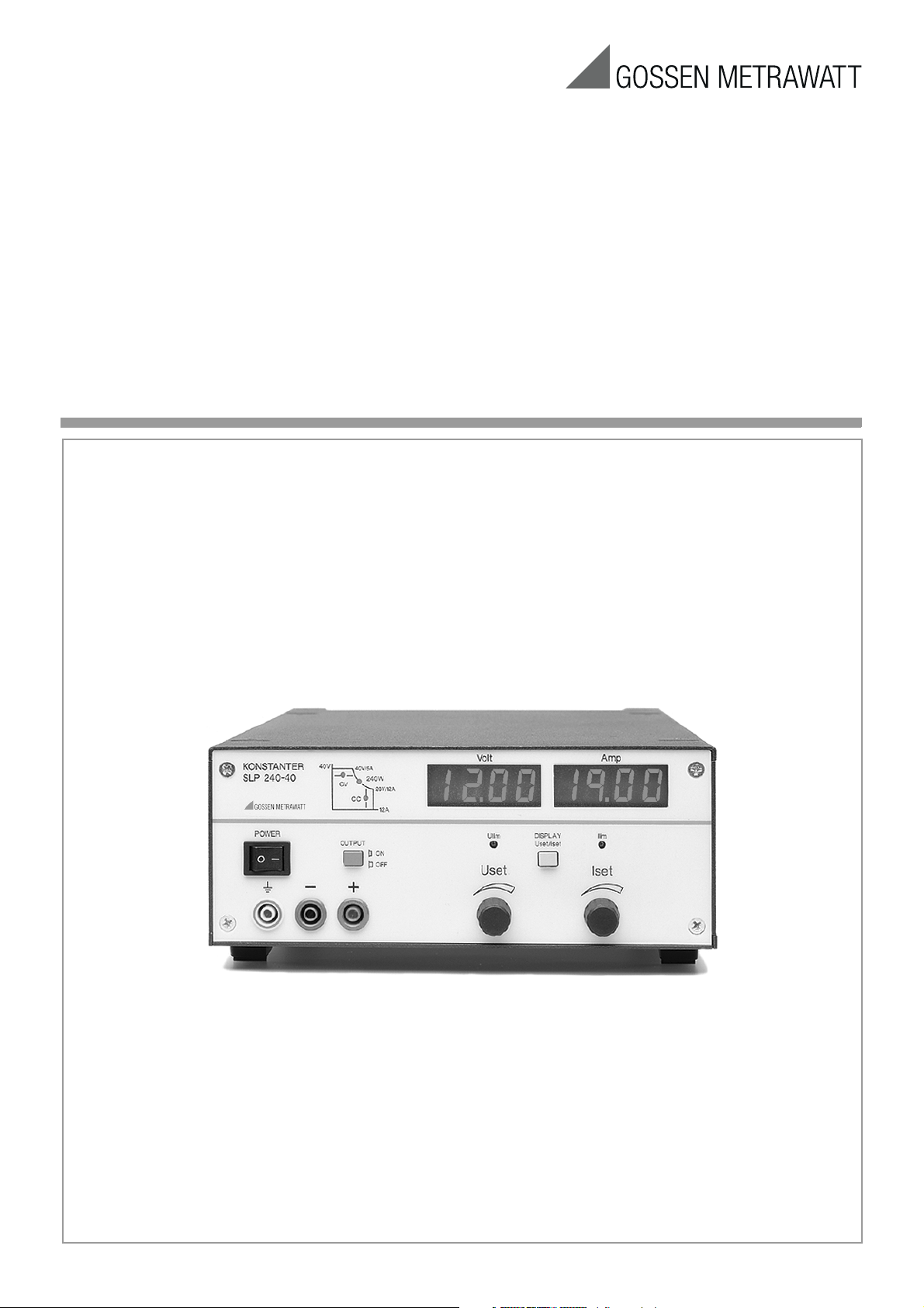
SLP-KONSTANTER 32N
Series SLP 120 /SLP 240 / SLP 320
Analog Controlled Laboratory Power Supplies
Page 2

2 GMC-I Messtechnik GmbH
Page 3

Contents
Page
Receiving Inspection . . . . . . . . . . . . . . . . . . . . . . . . . . . . . . . . . . . . . . . . . . . . . . . . . . . . . . . . . . . . . . . . . . . . . . . . . . . . . . . . . . . . . . . . . . . . . . . . . . .4
Warnings and Safety Precautions . . . . . . . . . . . . . . . . . . . . . . . . . . . . . . . . . . . . . . . . . . . . . . . . . . . . . . . . . . . . . . . . . . . . . . . . . . . . . . . . . . . . . . . . . .4
Important Warnings . . . . . . . . . . . . . . . . . . . . . . . . . . . . . . . . . . . . . . . . . . . . . . . . . . . . . . . . . . . . . . . . . . . . . . . . . . . . . . . . . . . . . . . . . . . . . . . . . . . .4
1 Technical Description . . . . . . . . . . . . . . . . . . . . . . . . . . . . . . . . . . . . . . . . . . . . . . . . . . . . . . . . . . . . . . . . . . . . . . . . . . . . . . . . . . . . . . . . . . . . . . . . . . .5
1.1 Range of Applications and Features . . . . . . . . . . . . . . . . . . . . . . . . . . . . . . . . . . . . . . . . . . . . . . . . . . . . . . . . . . . . . . . . . . . . . . . . . . . . . . . . . . . . . . . .5
1.2 Functional Characteristics . . . . . . . . . . . . . . . . . . . . . . . . . . . . . . . . . . . . . . . . . . . . . . . . . . . . . . . . . . . . . . . . . . . . . . . . . . . . . . . . . . . . . . . . . . . . . . .5
1.3 Options and Accessories . . . . . . . . . . . . . . . . . . . . . . . . . . . . . . . . . . . . . . . . . . . . . . . . . . . . . . . . . . . . . . . . . . . . . . . . . . . . . . . . . . . . . . . . . . . . . . . .5
1.4 Technical Data. . . . . . . . . . . . . . . . . . . . . . . . . . . . . . . . . . . . . . . . . . . . . . . . . . . . . . . . . . . . . . . . . . . . . . . . . . . . . . . . . . . . . . . . . . . . . . . . . . . . . . . 6
1.4.1 General Data . . . . . . . . . . . . . . . . . . . . . . . . . . . . . . . . . . . . . . . . . . . . . . . . . . . . . . . . . . . . . . . . . . . . . . . . . . . . . . . . . . . . . . . . . . . . . . . . . . . . . . . . .6
1.4.2 Electrical Data . . . . . . . . . . . . . . . . . . . . . . . . . . . . . . . . . . . . . . . . . . . . . . . . . . . . . . . . . . . . . . . . . . . . . . . . . . . . . . . . . . . . . . . . . . . . . . . . . . . . . . . .7
1.4.3 Mechanical Data . . . . . . . . . . . . . . . . . . . . . . . . . . . . . . . . . . . . . . . . . . . . . . . . . . . . . . . . . . . . . . . . . . . . . . . . . . . . . . . . . . . . . . . . . . . . . . . . . . . . .10
2 Preparation for Operation and Initial Start-Up . . . . . . . . . . . . . . . . . . . . . . . . . . . . . . . . . . . . . . . . . . . . . . . . . . . . . . . . . . . . . . . . . . . . . . . . . . . . . . . . .11
2.1 Connection to the Mains . . . . . . . . . . . . . . . . . . . . . . . . . . . . . . . . . . . . . . . . . . . . . . . . . . . . . . . . . . . . . . . . . . . . . . . . . . . . . . . . . . . . . . . . . . . . . . . 11
2.2 Connection to the Consuming Device . . . . . . . . . . . . . . . . . . . . . . . . . . . . . . . . . . . . . . . . . . . . . . . . . . . . . . . . . . . . . . . . . . . . . . . . . . . . . . . . . . . . . .11
2.3 Sensing Mode Operation . . . . . . . . . . . . . . . . . . . . . . . . . . . . . . . . . . . . . . . . . . . . . . . . . . . . . . . . . . . . . . . . . . . . . . . . . . . . . . . . . . . . . . . . . . . . . . .11
2.4 Installation to a 19" Rack . . . . . . . . . . . . . . . . . . . . . . . . . . . . . . . . . . . . . . . . . . . . . . . . . . . . . . . . . . . . . . . . . . . . . . . . . . . . . . . . . . . . . . . . . . . . . . .12
2.5 Multiple Benchtop Device Combination . . . . . . . . . . . . . . . . . . . . . . . . . . . . . . . . . . . . . . . . . . . . . . . . . . . . . . . . . . . . . . . . . . . . . . . . . . . . . . . . . . . . .12
3 Controls, Displays and Connectors . . . . . . . . . . . . . . . . . . . . . . . . . . . . . . . . . . . . . . . . . . . . . . . . . . . . . . . . . . . . . . . . . . . . . . . . . . . . . . . . . . . . . . . . 13
4 Adjusting Output Values . . . . . . . . . . . . . . . . . . . . . . . . . . . . . . . . . . . . . . . . . . . . . . . . . . . . . . . . . . . . . . . . . . . . . . . . . . . . . . . . . . . . . . . . . . . . . . . .15
4.1 Output Voltage. . . . . . . . . . . . . . . . . . . . . . . . . . . . . . . . . . . . . . . . . . . . . . . . . . . . . . . . . . . . . . . . . . . . . . . . . . . . . . . . . . . . . . . . . . . . . . . . . . . . . . .15
4.1.1 Uout – Presently Measured Voltage Value . . . . . . . . . . . . . . . . . . . . . . . . . . . . . . . . . . . . . . . . . . . . . . . . . . . . . . . . . . . . . . . . . . . . . . . . . . . . . . . . . . .15
4.1.2 Ulim – Limit Value for Uset . . . . . . . . . . . . . . . . . . . . . . . . . . . . . . . . . . . . . . . . . . . . . . . . . . . . . . . . . . . . . . . . . . . . . . . . . . . . . . . . . . . . . . . . . . . . .15
4.1.3 Uset – Voltage Setpoint Value . . . . . . . . . . . . . . . . . . . . . . . . . . . . . . . . . . . . . . . . . . . . . . . . . . . . . . . . . . . . . . . . . . . . . . . . . . . . . . . . . . . . . . . . . . . .15
4.2 Output Current . . . . . . . . . . . . . . . . . . . . . . . . . . . . . . . . . . . . . . . . . . . . . . . . . . . . . . . . . . . . . . . . . . . . . . . . . . . . . . . . . . . . . . . . . . . . . . . . . . . . . . 16
4.2.1 Iout – Presently Measured Current Value. . . . . . . . . . . . . . . . . . . . . . . . . . . . . . . . . . . . . . . . . . . . . . . . . . . . . . . . . . . . . . . . . . . . . . . . . . . . . . . . . . . .16
4.2.2 Ilim – Limit Value for Iset . . . . . . . . . . . . . . . . . . . . . . . . . . . . . . . . . . . . . . . . . . . . . . . . . . . . . . . . . . . . . . . . . . . . . . . . . . . . . . . . . . . . . . . . . . . . . . .16
4.2.3 Iset – Current Setpoint Value . . . . . . . . . . . . . . . . . . . . . . . . . . . . . . . . . . . . . . . . . . . . . . . . . . . . . . . . . . . . . . . . . . . . . . . . . . . . . . . . . . . . . . . . . . . 16
4.3 OUTPUT – Switching the Power Output On and Off . . . . . . . . . . . . . . . . . . . . . . . . . . . . . . . . . . . . . . . . . . . . . . . . . . . . . . . . . . . . . . . . . . . . . . . . . . . .16
5 Control via the Analog Interface . . . . . . . . . . . . . . . . . . . . . . . . . . . . . . . . . . . . . . . . . . . . . . . . . . . . . . . . . . . . . . . . . . . . . . . . . . . . . . . . . . . . . . . . . . 17
5.1 Connector Assignments . . . . . . . . . . . . . . . . . . . . . . . . . . . . . . . . . . . . . . . . . . . . . . . . . . . . . . . . . . . . . . . . . . . . . . . . . . . . . . . . . . . . . . . . . . . . . . . .17
5.2 Status Signal Outputs . . . . . . . . . . . . . . . . . . . . . . . . . . . . . . . . . . . . . . . . . . . . . . . . . . . . . . . . . . . . . . . . . . . . . . . . . . . . . . . . . . . . . . . . . . . . . . . . .18
5.3 Trigger Input . . . . . . . . . . . . . . . . . . . . . . . . . . . . . . . . . . . . . . . . . . . . . . . . . . . . . . . . . . . . . . . . . . . . . . . . . . . . . . . . . . . . . . . . . . . . . . . . . . . . . . . .18
5.4 Controlling Output Voltage . . . . . . . . . . . . . . . . . . . . . . . . . . . . . . . . . . . . . . . . . . . . . . . . . . . . . . . . . . . . . . . . . . . . . . . . . . . . . . . . . . . . . . . . . . . . . . 19
5.5 Controlling Output Current . . . . . . . . . . . . . . . . . . . . . . . . . . . . . . . . . . . . . . . . . . . . . . . . . . . . . . . . . . . . . . . . . . . . . . . . . . . . . . . . . . . . . . . . . . . . . . 19
5.6 Voltage Monitoring Output . . . . . . . . . . . . . . . . . . . . . . . . . . . . . . . . . . . . . . . . . . . . . . . . . . . . . . . . . . . . . . . . . . . . . . . . . . . . . . . . . . . . . . . . . . . . . .20
5.7 Current Monitoring Output . . . . . . . . . . . . . . . . . . . . . . . . . . . . . . . . . . . . . . . . . . . . . . . . . . . . . . . . . . . . . . . . . . . . . . . . . . . . . . . . . . . . . . . . . . . . . . 20
5.8 Parallel Operation . . . . . . . . . . . . . . . . . . . . . . . . . . . . . . . . . . . . . . . . . . . . . . . . . . . . . . . . . . . . . . . . . . . . . . . . . . . . . . . . . . . . . . . . . . . . . . . . . . . .21
5.8.1 Direct Parallel Operation . . . . . . . . . . . . . . . . . . . . . . . . . . . . . . . . . . . . . . . . . . . . . . . . . . . . . . . . . . . . . . . . . . . . . . . . . . . . . . . . . . . . . . . . . . . . . . .21
5.8.2 Parallel Master-Slave Operation . . . . . . . . . . . . . . . . . . . . . . . . . . . . . . . . . . . . . . . . . . . . . . . . . . . . . . . . . . . . . . . . . . . . . . . . . . . . . . . . . . . . . . . . . . 22
5.9 Series Operation . . . . . . . . . . . . . . . . . . . . . . . . . . . . . . . . . . . . . . . . . . . . . . . . . . . . . . . . . . . . . . . . . . . . . . . . . . . . . . . . . . . . . . . . . . . . . . . . . . . . .23
5.9.1 Direct Series Operation . . . . . . . . . . . . . . . . . . . . . . . . . . . . . . . . . . . . . . . . . . . . . . . . . . . . . . . . . . . . . . . . . . . . . . . . . . . . . . . . . . . . . . . . . . . . . . . .23
5.9.2 Series Master-Slave Operation . . . . . . . . . . . . . . . . . . . . . . . . . . . . . . . . . . . . . . . . . . . . . . . . . . . . . . . . . . . . . . . . . . . . . . . . . . . . . . . . . . . . . . . . . . . 24
5.10 Varying Internal Output Resistance . . . . . . . . . . . . . . . . . . . . . . . . . . . . . . . . . . . . . . . . . . . . . . . . . . . . . . . . . . . . . . . . . . . . . . . . . . . . . . . . . . . . . . . .25
6 Accessories. . . . . . . . . . . . . . . . . . . . . . . . . . . . . . . . . . . . . . . . . . . . . . . . . . . . . . . . . . . . . . . . . . . . . . . . . . . . . . . . . . . . . . . . . . . . . . . . . . . . . . . . .26
7 Order Information . . . . . . . . . . . . . . . . . . . . . . . . . . . . . . . . . . . . . . . . . . . . . . . . . . . . . . . . . . . . . . . . . . . . . . . . . . . . . . . . . . . . . . . . . . . . . . . . . . . .26
8 Repair and Replacement Parts Service
Calibration Center and Rental Service . . . . . . . . . . . . . . . . . . . . . . . . . . . . . . . . . . . . . . . . . . . . . . . . . . . . . . . . . . . . . . . . . . . . . . . . . . . . . . . . . . . . . .26
9 Product Support . . . . . . . . . . . . . . . . . . . . . . . . . . . . . . . . . . . . . . . . . . . . . . . . . . . . . . . . . . . . . . . . . . . . . . . . . . . . . . . . . . . . . . . . . . . . . . . . . . . . .26
GMC-I Messtechnik GmbH 3
Page 4

Receiving Inspection
Important Warnings
Immediately upon receipt, unpack the KONSTANTER and all included
accessories, and inspect for completeness and possible damage.
Unpacking
☞ Other than the usual degree of care required for the handling of
electronic devices, no special care must be exercised when
unpacking the instrument.
☞ The KONSTANTER is shipped in recyclable packaging which
provides for adequate protection during transport. If the
instrument needs to be repacked, the original packaging, or
equivalent packaging, must be used.
Visual Inspection
☞ Compare the order number or type designation found on the
packaging and/or the serial plate with the specifications
printed in the shipping documents.
☞ Make sure that all accessory components have been included
(→ 1.3 Options and Accessories).
☞ Inspect the packaging as well as instrument mechanisms for
possible transport damage.
Complaints
If damage is detected, file a damages report immediately with the
freight forwarder (save the packaging!). In the event of any other
defects or if service is required, please contact your service representative, or contact us directly at the address included in the last
page of these instructions.
Warnings and Safety Precautions
The KONSTANTER has been manufactured and tested in accor-
dance with the safety regulations specified in the technical data
section included in this chapter as a safety class I device. It has left
the factory in flawless technical safety conditions. In order to maintain this condition, and to assure safe use, the user must observe
all notes and warnings included in these operating instructions.
These are identified with the following headings:
CAUTION!
Operating instructions or practical information etc., which must be
observed in order to prevent damage to the KONSTANTER, and to assure
correct operation.
WARNING I – Protective Ground
The
KONSTANTER may only be operated with a connected protec-
tive conductor. Any interruption of the protective conductor, either
inside or outside of the KONSTANTER or disconnection of the pro-
tective conductor terminal, may render the KONSTANTER hazardous.
Intentional interruption is prohibited.
Mains connection is accomplished with a 3-conductor cable with
mains plug. The plug may only be inserted into a suitable mains
outlet with an earthing contact. The resulting protection must not
be rendered ineffective through the use of an extension cable
without protective conductor.
WARNING II – Impaired Safety Protection
If it may be assumed that safe operation is no longer possible, the
KONSTANTER must be removed from service and secured against
unintentional use. It must be assumed that safe operation is no
longer possible if:
KONSTANTER demonstrates visible damage
• The
KONSTANTER no longer functions
• The
• After lengthy periods of storage if specified storage conditions
have not been observed
• After excessive stress due to transport
WARNING III – Opening Housing Covers
Voltage conducting part may be exposed when housing covers
are opened, as long as the KONSTANTER is connected.
Touching these exposed voltage conducting parts is extremely life
endangering.
Housing covers may thus only be opened or removed by qualified
personnel who are familiar with the dangers involved.
WARNING IV – Repairs Performed by Qualified Personnel Only
Voltage conducting part may be exposed when housing covers
are opened, as long as the
Maintenance and repairs, as well as internal instrument balancing,
may only be performed by qualified personnel who are familiar with
the dangers involved.
In as far as possible, the KONSTANTER must be disconnected from
all external voltage sources before such work is performed. A 5
minute waiting period must be observed after disconnection, in
order to allow internal capacitors to discharge to safe voltage
levels.
KONSTANTER is connected.
WARNING!
Operating instructions or practical information etc., which must be
observed in order to maintain the safety features included with the
KONSTANTER, and to prevent personal injury.
The most important warnings are summarized below. Reference is made
to these warning at all appropriate points throughout the operating
instructions.
4 GMC-I Messtechnik GmbH
WARNING V – Replacing Fuses
When replacing blown fuses, use only specified fuse types with the
specified current ratings (see technical data or serial plate).
Tampering with the fuses or fuse holders (“mending” fuses, shortcircuiting fuse holders etc.) is prohibited.
Page 5

1 Technical Description
1.2 Functional Characteristics
1.1 Range of Applications and Features
The SLP-KONSTANTER is a single channel laboratory power supply
for universal use in R&D, production, training and service.
The KONSTANTER maintains either constant current or constant voltage
and is capable of delivering 120 W or 240 W of nominal power
over a broad range thanks to the auto-ranging output.
Precise manual settings for voltage and current are accomplished
with the help of ten-turn potentiometers. The setting range can be
reduced with a screwdriver, in order to prevent inadvertent
adjustment to unwanted, excessively high values.
Output voltage and current appear at two large-format 3½ place
digital LED displays, which can also be switched for the display of
setpoint values. Control mode displays indicate the respective
operating status.
The floating output at the front and rear panels can be activated and
deactivated by pressing a key, or with a signal to the analog interface which is provided as standard equipment. The instrument is
automatically switched to remote sensing as soon as sensor cables
are connected.
The sturdy metal housing is sealed at top and bottom, and is
equipped with rubber feet and a cable spacer at the rear panel.
With a minimum of effort, several housings can be mechanically
combined into a multi-channel unit. This unit requires only one
mains outlet which is looped through with the help of a mains
jumper cable (accessory) via the integrated mains outlet socket.
Installation to a 19" rack is also possible with the appropriate
adapter.
Adjustable functions
❏ Voltage and current setpoints
❏ Limit values for voltage and current setting ranges
❏ Output activation and deactivation
Display functions
❏ Measured voltage and current values
❏ Voltage and current setpoints
❏ Current control mode (CC/CV)
Protective and additional functions
❏ Reverse polarity protection for sensor terminals
with automatic activation (auto-sensing)
❏ Protection against excessive temperature
❏ Protection against output polarity reversal
❏ In-rush current limiting
❏ Temperature controlled fan
❏ Master-slave link
1.3 Options and Accessories
Options
No options are available for the KONSTANTER, above and beyond
the included standard equipment.
Included Accessories:
The following accessories are included with the KONSTANTER:
❏ These operating instructions
❏ 1 power cable (approx. 1.5 m long) with earthing contact plug
Additionally available accessories:
(see last page for order information)
❏ 19" adapter (1x32N) for installing 1 series SLP KONSTANTER to
a 19" rack
❏ 19" adapter (2x32N) for installing 2 series SLP KONSTANTERs to
a 19" rack
❏ Mains jumper cable, 0.4 m long
used for looping through mains power, equipped with a 10 A
plug and a 10 A socket for non-heating apparatus
GMC-I Messtechnik GmbH 5
Page 6
1.4 Technical Data
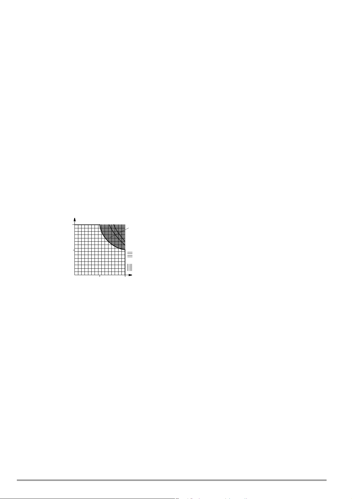
U/V
U
Nom
I/A
I
Nom
0
0.5 I
Nom
P
Nom
Intermittent
Working Range
Voltage Adj.
Current Adj.
Range
Range
0.5
U
Nom
1.4.1 General Data
Power Supply
Connection Input: 10 A IEC plug
Output: 10 A IEC socket,
Line Voltage 230 V~, +10 / –15%, 47 … 63 Hz
Power Consumption see 1.4.2
In-Rush Current max. 50 A
Mains Fuse 1 x T 4 A / 250 V (6.3 x 32 mm, UL)
internal: 1 x T 5 H / 250 V (5 x 20 mm)
Output
Connection
Output front panel, 2 ea. 4 mm safety socket
rear panel, 6-pole plug-in screw terminal
block
no switch, no fuse
S
10 U-MON Output voltage measurement output
(0 ... 10 V corres. to 0 ... U
, Ri = 9.8 kΩ)
nom
11 I-MON Output current measurement output
(0 ... 10 V corres. to 0 ... I
, Ri = 9.4 kΩ)
nom
Electrical Safety
Safety class I
Overvoltage
category II for mains input
I for output and interfaces
Fouling factor 2
Earth leakage
current 2.5 mA, typ.
IEC 61010-1:1990 + A1:1992 / DIN EN 61010-1: 1993 /
VDE 0411-1:1994
Sensor rear panel, 6-pole plug-in screw terminal
block
Regulator Type primary switched mode with BET
DIN VDE 0160:1988 + A1:1989 class W1
EN 60950:1992 / VDE 0805:1990
technology
Operating Modes adjustable constant voltage / constant cur-
rent source with automatic sharp transition
Output Isolation Floating output with “safety isolation” from
the mains input,
max. allowed potential output
-
earth:
120 V,
capacitive output-earth (housing): 60 nF
Output Working Range
Protection IP 20 for housing per
IEC 529:1989,
EN 60529:1991,
VDE 0470-1:1992
Electrical isolation Test voltage
Mains/output–PE 1.35 kV~
Mains–output 2.7 kV~ (type test: 3.7 kV ~)
Electromagnetic Compatibility (EMC)
Product standard EN 61326-1:1997 + A1: 1998
Interference
emission EN 55022:1998 class A
Interference
immunity EN 61000-4-2:1995, feature A
EN 61000-4-3:1996 + A1:1998,
feature B
EN 61000-4-4:1995, feature B
EN 61000-4-5:1995, feature B
EN 61000-4-6:1996, feature B
Intermittent Working Range:
Overtemperature protection may be
triggered, and the output deactivated, if
operated for lengthy periods of time in the
intermittent working range (see also
intermittent power, 1.4.2).
Analog Interface
Connection 11-pole plug-in screw terminal block
Reference Potential negative output pole,
floating TRG input
Connector Pin Assignments:
Pin Designation Function
1 SIG1 OUT Status signal output for output ON/OFF
(open collector, max. 30 V − / 20 mA)
2 SIG2 OUT Control mode status signal output CV / CC
Ambient Conditions
IEC 68-2-6 (’90) Resistance to Vibration
IEC 68-2-27 (’89) Impact Resistance
Temperature Range Operation: 0 ... 50 °C
Atmospheric Humidity Operation: ≤ 75% relative humidity,
Cooling With integrated fan
EN 61000-4-11:1994, feature B
(10 ... 55 Hz, 0.3 mm, 1 octave / min,
3 x 30 min)
(15 g, 11 ms, half-sine, 3 x 6 shocks)
current derating at > 40 °C
(see also 1.4.2.)
Storage: –25 ... +75 °C
no condensation
Air inlet: at side panels
Air outlet: at rear panel
(open collector, max. 30 V − / 20 mA)
3TRG IN + Digital control input for output ON/OFF
4TRG IN − (low: < 1 V, high: 4 ... 26 V), floating
5 +15 V Auxiliary voltage +15 V / max. 50 mA
6 AGND Reference point connected to − output via
automatic resetting fuse
7U
8U
9I
6 GMC-I Messtechnik GmbH
− Analog, negated voltage control input
set
+ Analog voltage control input
set
+ Analog current control input
set
(0 ... −5 V corres. to 0 ... U
(0 ... +5 V corres. to 0 ... U
(0 ... +5 V corres. to 0 ... I
non
nom
nom
, Ri = 10 kΩ)
, Ri = 10 kΩ)
, Ri = 10 kΩ)
Page 7

1.4.2 Electrical Data
Electrical Data, Series 120 W
If not otherwise specified, all entries are maximum values and are valid for an operating temperature range of 0 to 50 °C,
nominal power range and a line voltage range of 230 V ± 10% after a warm-up period of 30 minutes.
Description (abbreviated designation) SLP 120-20 SLP 120-40 SLP 120-80
Typ e 32 N 20 R 10 32 N 40 R 6 32 N 80 R 3
Nominal Output Data Voltage setting range 0 ... 20 V 0 ... 40 V 0 ... 80 V
Current setting range 0 ... 10 A 0 ... 6 A 0 ... 3 A
Continuous power where Tu ≤ 40 °C max. 120 W max. 120 W max. 120 W
Intermittent power where t < 90 s / Tu ≤ 25 °C max. 200 W max. 240 W max. 240 W
Current derating where Tu > 40 °C – 0.25 A / K – 0.15 A / K – 0.07 A / K
Output Operating Characteristics
Overall setting accuracy at 23 ± 5 °C
with reference to 3½ place setpoint display
including system deviation, load / mains
Static system deviation
at 100% load variation
Static system deviation
at 10% line voltage variation
Residual ripple
Ua > 5% U
nom
1)
1)
1)
1)
1)
Voltage (10 Hz ... 10 MHz)
Current (10 Hz ... 1 MHz)
Common-mode noise (10 Hz ... 1 MHz) 0.5 mA
Settling time (voltage)
with sudden load variation of 10 ... 90% I
nom
Under and overshooting with sudden load variation of
(Typical values) Δ I = 80%
(Typical values) Δ I = 80% 400 mV 400 mV 800 mV
50 A / ms
Settling time (voltage)
with setpoint jump: 0 → 100%
with setpoint jump: 100% → 0
no load / nominal load
no load / nominal load
Settling time (current)
with setpoint jump: 0 → 100%
with setpoint jump: 100% → 0
short-circuit / nominal load
short-circuit / nominal load
Measured Value Displays (3½ place)
Measurement resolution Voltage
Measuring accuracy at 23 ± 5 °C
with reference to the respective measured value
Protective Functions
Output overvoltage protection Threshold 25 ± 1 V 50 ± 2 V 100 ± 4 V
Reversed polarity protection – overload capacity Continuous 10 A 6 A 3 A
Reverse flow resistance Continuous 40 V 80 V 100 V
General
Power supply
1)
Power Consumption At nominal load
At max. intermittent power
Efficiency At nominal load > 70% > 80% > 80%
Switching frequency Typical 200 kHz 200 kHz 200 kHz
Article number K220A K221A K222A
1) Typical values are increased by a factor of approximately 1.2 in the functional line voltage input range of –10% to –15%.
Voltage
Current
Voltage
Current
Voltage
Current
0.2% + 50 mV
0.5% + 45 mA
15 mV
20 mA
5 mV
8 mA
10 mV
25 mA
To le ra nc e
40 mV
200 μs
To le ra nc e
40 mV
1 ms / 1 ms
1 ms / 1 ms
To le ra nc e
100 mA
< 5 ms / < 5 ms
< 5 ms / < 5 ms
10 mV
Current
Voltage
Current
10 mA
0.15% + 25 mV
0.5% + 30 mA
Line voltage 230 V~ +10 / −15%
47 ... 63 Hz
280 VA, 180 W
In standby mode
45 VA, 15 W
450 VA
0.2% + 150 mV
0.5% + 35 mA
10 mV
10 mA
5 mV
5 mA
eff
eff
eff
10 mV
20 mA
0.5 mA
eff
eff
eff
80 mV
200 μs
80 mV
1 ms / 1 ms
1 ms / 1 ms
60 mA
< 5 ms / < 5 ms
< 5 ms / < 5 ms
100 mV
10 mA
0.2% + 120 mV
0.5% + 25 mA
230 V~ +10 / −15%
47 ... 63 Hz
280 VA, 150 W
45 VA, 15 W
500 VA
0.2% + 250 mV
0.5% + 20 mA
10 mV
10 mA
5 mV
5 mA
10 mV
10 mA
0.5 mA
80 mV
200 μs
160 mV
4 ms / 4ms
4 ms / 4ms
30 mA
< 10 ms / < 10 ms
< 10 ms / < 10 ms
100 mV
10 mA
0.2% + 150 mV
0.5% + 20 mA
230 V~ +10 / −15%
47 ... 63 Hz
280 VA, 170 W
45 VA, 15 W
500 VA
eff
eff
eff
GMC-I Messtechnik GmbH 7
Page 8

Electrical Data, Series 240 W
If not otherwise specified, all entries are maximum values and are valid for an operating temperature range of 0 to 50 °C,
nominal power range and a line voltage range of 230 V ± 10% after a warm-up period of 30 minutes.
Description (abbreviated designation) SLP 240-20 SLP 240-40 SLP 240-80
Typ e 32 N 20 R 20 32 N 40 R 12 32 N 80 R 6
Nominal Output Data Voltage setting range 0 ... 20 V 0 ... 40 V 0 ... 80 V
Current setting range 0 ... 20 A 0 ... 12 A 0 ... 6 A
Continuous power where Tu ≤ 40 °C max. 240 W max. 240 W max. 240 W
Intermittent power where t < 90 s / Tu ≤ 25 °C max. 320 W max. 360 W max. 360 W
Current derating where Tu > 40 °C – 0.5 A / K – 0.3 A / K – 0.15 A / K
Output Operating Characteristics
Overall setting accuracy at 23 ± 5 °C
with reference to 3½ place setpoint display
including system deviation, load / mains
Static system deviation
at 100% load variation
Static system deviation
at 10% line voltage variation
Residual ripple
Ua > 5% U
nom
1)
1)
1)
1)
1)
Voltage (10 Hz ... 10 MHz)
Current (10 Hz ... 1 MHz)
Common-mode noise (10 Hz ... 1 MHz) 0.5 mA
Settling time (voltage)
with sudden load variation of 10 ... 90% I
nom
Under and overshooting with sudden load variation of
(Typical values) Δ I = 80%
(Typical values) Δ I = 80% 450 mV 450 mV 800 mV
50 A / ms
Settling time (voltage)
with setpoint jump: 0 → 100%
with setpoint jump: 100% → 0
no load / nominal load
no load / nominal load
Settling time (current)
with setpoint jump: 0 → 100%
with setpoint jump: 100% → 0
short-circuit / nominal load
short-circuit / nominal load
Measured Value Displays (3½ place)
Measurement resolution Voltage
Measuring accuracy at 23 ± 5 °C
with reference to the respective measured value
Protective Functions
Output overvoltage protection Threshold 25 ± 1 V 50 ± 2 V
Reversed polarity protection – overload capacity Continuous 20 A 12 A 6 A
Reverse flow resistance Continuous 40 V 80 V 100 V
General
Power supply
1)
Power Consumption At nominal load
At max. intermittent power
Efficiency At nominal load > 68% > 70% > 70%
Switching frequency Typical 200 kHz 200 kHz 200 kHz
Article number K230A K231A K232A
1) Typical values are increased by a factor of approximately 1.2 in the functional line voltage input range of –10% to –15%.
Voltage
Current
Voltage
Current
Voltage
Current
0.2% + 100 mV
0.5% + 55 mA
25 mV
30 mA
5 mV
8 mA
15 mV
50 mA
To le ra n ce
40 mV
600 μs
To le ra n ce
40 mV
1 ms / 1 ms
1 ms / 1 ms
To le ra n ce
200 mA
< 5 ms / < 5 ms
< 5 ms / < 5 ms
10 mV
Current
Voltage
Current
10 mA
0.2% + 50 mV
0.5% + 25 mA
Line voltage 230 V~ +10 / −15%
47 ... 63 Hz
510 VA, 350 W
In standby mode
45 VA, 15 W
620 VA
0.2% + 150 mV
0.5% + 45 mA
18 mV
30 mA
5 mV
8 mA
eff
eff
eff
15 mV
25 mA
0.5 mA
eff
eff
eff
80 mV
300 μs
80 mV
1 ms / 1 ms
1 ms / 1 ms
120 mA
< 5 ms / < 5 ms
< 5 ms / < 5 ms
100 mV
10 mA
0.2% + 120 mV
0.5% + 30 mA
0.2% + 250 mV
0.5% + 35 mA
18 mV
15 mA
5 mV
5 mA
15 mV
20 mA
0.5 mA
160 mV
200 μs
160 mV
4 ms / 4ms
4 ms / 4ms
60 mA
< 10 ms / < 10 ms
< 10 ms / < 10 ms
100 mV
10 mA
0.2% + 120 mV
0.5% + 25 mA
100 ± 4 V
230 V~ +10 / −15%
47 ... 63 Hz
500 VA, 340 W
45 VA, 15 W
690 VA
230 V~ +10 / −15%
47 ... 63 Hz
500 VA, 340 W
45 VA, 15 W
690 VA
eff
eff
eff
8 GMC-I Messtechnik GmbH
Page 9

Electrical Data, Series 320 W
If not otherwise specified, all entries are maximum values and are valid for an operating temperature range of 0 to 50 °C,
nominal power range and a line voltage range of 230 V ± 10% after a warm-up period of 30 minutes.
Description (abbreviated designation) SLP 320-32
Typ e 32 N 32 R 18
Nominal Output Data Voltage setting range 0 ... 32 V
Current setting range 0 ... 18 A
Continuous power where Tu ≤ 40 °C max. 320 W
Intermittent power where t < 90 s / Tu ≤ 25 °C max. 430 W
Current derating where Tu > 40 °C – 0.5 A / K
Output Operating Characteristics
Overall setting accuracy at 23 ± 5 °C
with reference to 3½ place setpoint display
including system deviation, load / mains
Static system deviation
at 100% load variation
Static system deviation
at 10% line voltage variation
Residual ripple
Ua > 5% U
nom
1)
1)
1)
1)
1)
Voltage (10 Hz ... 10 MHz)
Current (10 Hz ... 1 MHz)
Common-mode noise (10 Hz ... 1 MHz) 0.5 mA
Settling time (voltage)
with sudden load variation of 10 ... 90% I
nom
Under and overshooting with sudden load variation of
(Typical values) Δ I = 80%
(Typical values) Δ I = 80% 450 mV
50 A / ms
Settling time (voltage)
with setpoint jump: 0 → 100%
with setpoint jump: 100% → 0
no load / nominal load
no load / nominal load
Settling time (current)
with setpoint jump: 0 → 100%
with setpoint jump: 100% → 0
short-circuit / nominal load
short-circuit / nominal load
Measured Value Displays (3½ place)
Measurement resolution Voltage
Measuring accuracy at 23 ± 5 °C
with reference to the respective measured value
Protective Functions
Output overvoltage protection Threshold 40 ± 1 V
Reversed polarity protection – overload capacity Continuous 20 A
Reverse flow resistance Continuous 64 V
General
Power supply
1)
Power Consumption At nominal load
At max. intermittent power
Efficiency At nominal load > 69%
Switching frequency Typical 200 kHz
Article number K234A
1) Typical values are increased by a factor of approximately 1.2 in the functional line voltage input range of –10% to –15%.
Voltage
Current
Voltage
Current
Voltage
Current
0.2% + 150 mV
0.5% + 50 mA
30 mV
40 mA
10 mV
20 mA
30 mV
50 mA
(Ua > 10%U
eff
To le ra nc e
64 mV
500 μs
To le ra nc e
64 mV
1 ms / 1 ms
1 ms / 1 ms
To le ra nc e
180 mA
< 5 ms / < 5 ms
< 5 ms / < 5 ms
100 mV
Current
Voltage
Current
10 mA
0.2% + 120 mV
0.5% + 40 mA
Line voltage 230 V~ +10 / −15%
47 ... 63 Hz
650 VA, 460 W
In standby mode
50 VA, 15 W
770 VA
eff
)
nom
eff
GMC-I Messtechnik GmbH 9
Page 10

1.4.3 Mechanical Data
All dimensions in mm
CC
CV
DISPLAY
Volt
Amp
Iset
Uset
POWER
OFF
ON
Uset/Iset
240W
40V
12A
20V/12A
40V/6A
OUTPUT
Ulim Ilim
230V 50-60Hz
FUSE T4/250V
OUTPUTANALOG INTERFACE
SIG1 OUT
SIG2 OUT
TRG IN
TRG IN
15V
AGND
Uset
Uset
Iset
U-MON
I-MON
SENSE
+
-
SENSE
+
-
+
-
+
+
-
+
397.5
221.5
380.5
88
14
Mechanical Design
Benchtop instrument, suitable for rack mounting
Dimensions See also dimensional drawing
(W x H x D) 221.5 x 102 x 397.5 mm
For 19" rack ½19" x 2 standard height units x 400 mm
Weight approx. 2.8 kg
Dimensional Drawing
10 GMC-I Messtechnik GmbH
Page 11

2 Preparation for Operation and
Initial Start-Up
2.1 Connection to the Mains
Observe WARNING I!
CAUTON!
Before switching the KONSTANTER on, make sure that your local mains
voltage corresponds with the operating voltage specified on the
instrument’s rear panel.
The KONSTANTER requires 230 V~ supply power. Connect the
recessed mains plug at the back of the device to a mains outlet
with earthing contact with the included power cable.
Power consumption is specified on the serial plate at the back of
the KONSTANTER.
A mains outlet socket is located above the recessed plug and
can be used for looping mains power through to additional
instruments.
This mains outlet is neither switched nor fused.
increasing voltage as required at the output jacks.
☞ Voltage limiting remains uninfluenced by output current as well
during constant current operation.
☞ The voltage value determined by the measuring function
corresponds to voltage acquired by the sensing leads. Load
parameters such as power consumption and load impedance
can thus be more precisely determined.
• The parameters and limit values listed in figure 2.3 apply for
operation with sensing leads.
WARNING!
If mains power is looped through, make sure that overall power
consumption does not exceed 10 A at the point from which power is
drawn from the mains!
Suitable “mains jumper cables” are available as an accessory (see
order information on last page).
2.2 Connection to the Consuming Device
Supply power to the consuming device is connected either at the
front panel with 4 mm safety plugs to the safety jacks identified
with the “+” and “−” markings, or to the “+” and “−” outputs at the
6-pole terminal strip at the rear panel.
Connections for the consuming device at the
“+” and
These must be connected in parallel for load currents of greater than 10 A
due to contact ratings.
Be certain to use conductors with an adequate cross-section and observe
correct polarity. It is advisable to twist the power leads to the consuming
device, and to identify polarity with markings at their ends.
If connections are made simultaneously at the front and the rear
panel, constant voltage regulation applies to the terminals at the
rear panel. This is not permitted for parallel connection because the
internal connection might otherwise be overloaded.
The yellow-green safety jack at the front panel is connected to PE,
and can be used to connect earthing cables or cable shields, or as
an earth connection point for one of the output terminals.
two “−
” terminals.
rear panel
include
two
2.3 Sensing Mode Operation
In order to take advantage of highly constant output voltage, even
if long leads are used for connection to the consuming device,
voltage drops at the power leads can be compensated for with
additional sensing leads.
Function
• Sensing terminals: +SENSE / −SENSE
Output voltage, which is decisive for the voltage measuring and
regulating circuits, is acquired directly at the consuming device
(instead of at the output terminals).
• Sensing mode operation (remote sensing) offers the following
advantages:
☞ Voltage at the consuming device remains largely uninfluenced
by current-dependent voltage drops at the power supply leads
during constant voltage operation.
Voltage drops are compensated for by automatically
Figure 2.3 Connection to Consumer for Sensing Mode Operation
• Cs+, Cs-typically ... 220 μF
s+,Us-
≤ 1 V
− Us+ / 81 Ω
Us– / 81 Ω
• U
• I
s+
• I
s-
Connection
• The +SENSE and –SENSE leads from the output plug connector at
the rear panel should be connected as close as possible to the
corresponding terminals at the power consuming device.
• Interference injection can be minimized as follows:
☞ Twist the sensing leads and/or
☞ Shield the sensing leads.
(Connect shield to ground/housing or neg. output terminal.)
• Impedance resulting from long power and sensing leads may lead to
control oscillation at the output.
Capacitance at the consumer promotes this problem as well.
• Control oscillation can be counteracted by connecting
capacitors (C
(see figure 2.3).
• Twisting the power leads reduces their impedance as well.
• Incorrect connection of the sensing leads does not cause any damage
to the KONSTANTER, although it results in the following reversible
events:
, Cs-) between the SENSE and the output terminals
s+
☞ Sensing lead polarity reversal or power lead interruption
If output voltage from the KONSTANTER is not limited with the
current regulator, it rises to well above the setpoint value.
Overvoltage protection is then immediately triggered and the
output is deactivated.
☞ Sensing lead interruption
If one of the sensing leads is interrupted, the device is
switched automatically to local sensing for the
corresponding output terminal.
• If the sensing leads are connected incorrectly, voltage present
at the output terminals or consuming device is not displayed.
Activating Sensing Mode Operation
• Sensing mode operation is activated automatically after
connecting the SENSE terminal to the consumer which has
been connected to the output terminals.
• Sensing mode operation is deactivated as soon as this
connection has been interrupted.
GMC-I Messtechnik GmbH 11
Page 12

2.4 Installation to a 19" Rack
➁
➀
➀
➁
½19“ Blanking Plate
19“ Limit Stop
➃
➂
19" Joiner
19" Limit Stop
➃
➃
➂
The housing included with the KONSTANTERs has been designed for
use as a benchtop device, as well as for installation to a 19" rack.
Two KONSTANTERs can be installed next to one another, or a single
device can be installed along with a blanking plate. Benchtop
devices can be quickly converted for installation to a 19" rack.
Installing a Single KONSTANTER to a 19" Rack
Use the 19" adapter set accessory 1x32N.
It includes an 19" limit stop and a ½19" blanking plate.
➀ Loosen the 4 screws at the front panel of the
KONSTANTER.
➁ Pull out the two filler strips from the left and right-hand sides at
the front of the side panels.
Figure 2.4 Rack Conversion for a Single Device
➂ Replace the filler strips with the 19" limit stop on one side, and
the ½19" blanking plate on the other side. Fasten the limit stop
and the blanking plate with the 4 screws.
➃ Unscrew the feet from the bottom of the device. Remove the
rubber inserts from the feet first, behind which the screws are
concealed.
➄ Install the KONSTANTER into the rack. Keep all remaining parts in
a safe place for possible future use.
➅ The KONSTANTER must be supported in the rack at one side with
slide rails. The slide rails, as well as the screws required for
securing the KONSTANTER’s front panel are rack-specific, and
must thus be obtained from your rack supplier.
➂ Replace the filler strips with the 19" limit stops at the right and
left-hand sides, and with the 19" joiner in the middle. Fasten
the limit stops and the joiner with the 8 screws.
Screw the housings together at the threaded through-holes in
the cable spacers at the back of the devices.
➃ Unscrew the feet from the bottom of the devices. Remove the
rubber inserts from the feet first, behind which the screws are
concealed.
➄ If the two KONSTANTERs are to be electrically connected to one
another, use the accessory “mains jumper cable”.
➅ Install the KONSTANTERs into the rack. Keep all remaining parts
in a safe place for possible future use.
➆ The KONSTANTERs must be supported in the rack at both sides
with slide rails. The slide rails, as well as the screws required
for securing the KONSTANTER’s front panels are rack-specific,
and must thus be procured from your rack supplier.
2.5 Multiple Benchtop Device Combination
Up to 3 KONSTANTERs can be stacked to create a multiple bench-
top device combination (see also chapter 5 regarding possible
electrical connections via the analog interface).
➀ Unscrew the feet from the bottom of the device. Remove the
rubber inserts from the feet first, behind which the screws are
concealed.
Four large slotted holes are now visible at the bottom of the
device.
➁ Turn the four collar screws from the device feet into the threads
at the top of the other device housing. Keep the 4 lock
washers and device feet in a safe place.
➂ Set the KONSTANTER without feet on top of the other KONSTAN-
TER. The screws from the bottom device must protrude
through the enlarged openings in the bottom of the top device.
Push the top device back slightly, until the screws snap into
place.
➃ Screw the housings together at the threaded through-holes in
the cable spacers at the back of the devices. This secures the
top device against slipping.
➄ If the two KONSTANTERs are to be electrically connected to one
another, use the accessory “mains jumper cable”.
Conversion for Installing Two
Use the 19" adapter set accessory 2x32N.
It includes two 19" limit stops and one 19" joiner.
KONSTANTERs to a 19" Rack
➀ Loosen the 8 screws from the front panels at the KONSTANTERs.
➁ Pull out the two filler strips from the left and right-hand sides of
the front of the side panels at each device.
Figure 2.4 Rack Conversion for Two Devices
12 GMC-I Messtechnik GmbH
Page 13

3 Controls, Displays and Connectors
123 4 5
101196
87
Figure 3.1 Front Panel Controls, Displays and Connectors
[1] Mains Switch <POWER>
For switching the KONSTANTER on and off.
After mains power has been switched on, the KONSTANTER
adjusts itself to all of the values which have been predetermined by manual control settings or signals received at the
analog interface. It is then switched to the standby mode
and is ready for operation.
When the KONSTANTER is switched off, it is disconnected at
both poles from the mains and the output is deactivated.
CAUTION!
Do not switch the device on and off repeatedly at short intervals.
Effectiveness of in-rush current limiting may be impaired in such
cases, which may cause the mains fuse to blow!
[2] Output ON/OFF key <OUTPUT>
The power output is activated and deactivated by
pressing the <OUTPUT> key.
If the output is active, one of the control mode displays lights
up, namely CV or CC [3].
No significant output voltage overshooting occurs during
activation and deactivation of the power output.
When the device is switched off, an electronic sink is activated for approximately 300 ms, which rapidly discharges
the output capacitors. The output then becomes “highly
resistive” (R
> 50 kΩ II 250 μF).
i
[4] Left-Hand Display
The measured value for output voltage Uout in volts appears as
the standard display value at the left-hand display.
As long as the <DISPLAY Uset/Iset> key [9] is depressed, the
manually selected voltage setpoint Uset appears at the display.
Type / Nom.Voltage Display Resolution / Range
20 V 0.01 (max. 19.99)
32/40/80 V 0.1 (xx.x)
[5] Right-Hand Display
The measured value for output current Iout in amperes appears
as the standard display value at the right-hand display.
As long as the <DISPLAY Uset/Iset> [9] key is depressed, the
manually selected current setpoint Iset appears at the display.
Display Resolution / Range 0.01 (max. 19.99)
☞ Refer to chapter 4.3 for detailed information.
[6] Front Panel Output
The selected constant voltage or constant current is made
available at the safety jacks at the front panel, or at the
terminals on the rear panel [13].
– (blue) Negative output terminal
+ (red) Positive output terminal
(yellow-green) The output can be grounded here if
☞ Refer to chapter 4.3 for detailed information.
CAUTION!
The output terminals are not electrically isolated when the output is
deactivated.
desired, or the shield can be connected here if shielded power leads
are used. The ground terminal is connected to the housing and the mains
connection earthing contact.
[3] Control Mode Displays
The three LEDs indicate the current operating status (control
mode) of the output.
“CV” illuminated Constant voltage mode (Uout = Uset)
“CC” illuminated Constant current mode (Iout = Iset)
“Pmax” illuminated Overload limiting / overtemperature
protection has been triggered.
The output is deactivated as a result.
GMC-I Messtechnik GmbH 13
☞ Refer to chapter 2.2 for detailed information.
Page 14

Figure 3.2 Controls and Connectors at the Rear Panel
+
-
+
+
-
+
+
SENSE
-+
SENSE
I-MON
U-MON
Iset
Uset
Uset
AGND
15V
TRG IN
TRG IN
SIG2 OUT
SIG1 OUT
ANALOG INTERFACE OUTPUT
230V 50-60Hz
FUSE T4/250V
12 13
14
15
16
[7] Limit Value Adjustment <Ulim>
The upper limit value Ulim for the voltage setting range is
selected with this trimming potentiometer. Use a size 3
screwdriver only for this adjustment.
☞ Refer to chapter 4.1.2 for detailed information.
[8] Rotary Knob for Voltage Setpoint Adjustment <Uset>
Output voltage can be set with this rotary knob. Adjustment
is accomplished with a ten-turn potentiometer and allows for
precise adjustment of the voltage setpoint Uset, selected
within the range defined by means of Ulim [7].
Press the key [9] in order to display the setpoint value Uset.
☞ Refer to chapter 4.1.3 for detailed information.
[9] Display Switching Key <Uset/Iset>
The two displays [4/5] can be switched from Uout/Iout to
Uset/Iset by pressing the key [9].
The key must be pressed and held in order to continuously
monitor changes to Uset/Iset or Ulim/Ilim during adjustment.
[10] Rotary Knob for Current Setpoint Adjustment <Iset>
This rotary knob functions just like the rotary knob for voltage setpoint adjustment [8].
The display can be switched to the present current setpoint
value Iset by pressing the key [9] <DISPLAY Uset/Iset>.
☞ Refer to chapter 4.2.3 for detailed information.
[11] Limit Value Adjustment <Ilim>
The upper limit value Ilim for the current setting range is
selected with this trimming potentiometer. Use a size 3
screwdriver only for this adjustment.
☞ Refer to chapter 4.2.3 for detailed information.
[12] Analog Interface
CAUTION!
The contacts at the analog interface are connected to electronic
components which may be damaged by electrostatic discharge.
Before touching any contacts, neutralize the potential difference
between yourself and the KONSTANTER by touching the housing!
The analog interface provides for the following functions:
• Remote setting of output voltage and current with analog
control voltages ranging from 0 to 5 V or −5 to 0 V
☞ Refer to chapters 5.4 and 5.5 for detailed information.
• External measurement or recording of output voltage
and current by means of monitor signals ranging from
0 to 10 V
☞ Refer to chapters 5.6 and 5.7 for detailed information.
• +15 V auxiliary power supply to the trigger input or
external control devices
• Linking of several KONSTANTERs for master-slave operation
☞ See chapters 5.8.2 and 5.9.2 for detailed information.
• For varying internal output resistance
☞ Refer to chapter 5.10 for detailed information.
• For activating and deactivating the output via the floating
TRIGGER input
☞ Refer to chapter 5.3 for detailed information.
[13] Rear Panel Output
The OUTPUT interface can be used for two different
functions:
• Pick off constant voltage or constant current from the
rear panel of the KONSTANTER via the terminal strip
• Connect the sensing leads for the compensation of
voltage drops at the power leads
☞ Refer to chapters 2.2 and 2.3 for detailed information.
[14] Air Outlet
The air outlet vents regulate temperature inside the KONSTANTER. Warm air generated during operation is exhausted via
the air outlet vents with the help of a temperature controlled
fan.
CAUTION!
The air outlet may not be closed off and, it must be possible for
warm air to be exhausted freely via the air outlet vents. Nonobservance may trigger overtemperature protection and deactivate
the output (see chapter 4.3).
[15] Mains Power Input
Mains power input with looped through mains outlet for
connection to inlet connectors for non-heating apparatus.
The looped through mains outlet allows for direct connection
of up to 3 KONSTANTERs with two short power cables with
inlet connectors for non-heating apparatus. Only one power
cable is thus required for operation of three devices.
☞ Refer to chapter 2.1 for detailed information.
[16] Mains Fuse
Fusing at the mains power input:
All device types: T 4.0 A / 250 V (6.3 x 32 mm)
The second mains input pole is fused internally with:
T 5.0 A / 250 V (5 x 20 mm)
WARNING!
When replacing blown fuses, use only fuses of the specified type
with the specified current rating.
Any tampering with fuses or the fuse holder (“mending” fuses or
short-circuiting the fuse holder etc.) is strictly prohibited.
14 GMC-I Messtechnik GmbH
Page 15

4 Adjusting Output Values
4.1 Output Voltage
4.1.1 Uout – Presently Measured Voltage Value
• The left-hand digital display [4] <Volt> indicates the measured
value Uout for voltage present at the output terminals.
• During sensing mode operation, the displayed value
corresponds to voltage acquired from the sensing leads
at the consuming device.
• The 3½ place measured value display is refreshed approxi-
mately 3 times per second. Overflow is indicated for measured
values of greater than 19.99 at 20 V devices.
• If output voltage is superimposed with an alternating voltage,
the arithmetic mean value is displayed.
☞ Refer to chapter 1.4.3, Electrical Data, regarding measuring
range, measuring resolution and measuring accuracy.
4.1.2 Ulim – Limit Value for Uset
Function
• Defines the voltage adjustment setting range <Uset> [8]
• Prevents inadvertent, excessively high voltage setpoint values
(Uset) during manual operation.
• If Ulim is set to 0 V (full left), the voltage adjusting
potentiometer <Uset> is disabled (e.g. for adjustment of output
voltage by means of the analog interface).
Setting Ulim
• Ulim is adjusted with the left-hand trimming potentiometer [7]
<Ulim>.
• Use a size 3 screwdriver only in order to avoid damaging the
potentiometer.
• Deactivate the output: <OUTPUT> ”OFF”.
• First set Uset to its maximum value (turn potentiometer [8] <Uset>
clockwise as far as it will go).
• Press the key [9] <DISPLAY Uset/Iset>.
• The left-hand display [4] <Volt> is switched from the presently
measured voltage value Uout to the manually selected voltage
setpoint Uset.
• Hold this key depressed.
• At the same time, turn <Ulim> [7] with the screwdriver until <Volt>
appears at the display [4] as the selected voltage for Ulim.
• To increase voltage:Turn clockwise
• To decrease voltage:Turn counterclockwise
• The selected voltage is now the maximum voltage value to which
Uset can be adjusted manually.
4.1.3 Uset – Voltage Setpoint Value
Function
• Predefined voltage at which the consuming device is to be
operated
Adjusting Uset
• Uset is adjusted with the left-hand rotary knob [8] <Uset>.
• First press the key [9] <DISPLAY Uset/Iset>.
• The left-hand display [4] <Volt> is switched from the presently
measured voltage value Uout to the manually adjusted voltage
setpoint Uset.
• Hold this key depressed.
• At the same time, turn the rotary knob [8] <Uset>.
• To increase voltage:Turn clockwise
• To decrease voltage:Turn counterclockwise
• If the output is activated <OUTPUT> “ON”, output voltage is
adjusted directly by turning rotary knob.
• If the output is deactivated <OUTPUT> “OFF”, no voltage is present
at the output during adjustment. Voltage is not applied to the
output until it is activated <OUTPUT> “ON”.
• After releasing the key [9] <DISPLAY Uset/Iset>, the display [4] is
switched back to the measured value for output voltage Uout.
CAUTION!
The Uset value can also be changed when the KONSTANTER is not in
operation.
Setting Range
• The rotary knob can be turned 10 revolutions.
• The 10 revolutions which are possible with the <Uset>
potentiometer [8] always correspond to a range of 0 V to Ulim.
• The selection of a low value for Ulim allows for “finer” adjustment
of the Uset value.
The setting accuracy specified in chapter 1.4.3 makes reference
to the respectively displayed setpoint value.
• 19.99 is the highest value which can be displayed for Uout and
Uset with 20 V devices.
The A-D converter generates an overflow display for values
beyond this limit:
Setting Range
• The <Ulim> potentiometer can be turned 270°, which
corresponds to a setting range of 0 V
• The 10 revolutions which are possible with the <Uset> rotary knob
[8] always correspond to a range of 0 V to Ulim.
GMC-I Messtechnik GmbH 15
≤ Ulim ≤ Unom.
Page 16

4.2 Output Current
4.3 OUTPUT – Switching the Power Output On and Off
4.2.1 Iout – Presently Measured Current Value
• The right-hand digital display [5] <Amp> indicates the measured
value Iout for current at the output.
• If output current is superimposed with an alternating current,
the arithmetic mean value is displayed.
• The 3½ place measured value display is refreshed approxi-
mately 3 times per second. Overflow is indicated for measured
values of greater than 19.99 at 20 A devices.
☞ Refer to chapter 1.4.3, Electrical Data, regarding measuring
range, measuring resolution and measuring accuracy.
4.2.2 Ilim – Limit Value for Iset
Function
• Defines the current adjustment setting range <Iset> [8].
• Prevents inadvertent, excessively high Iset values.
• If Ilim is set to 0 V (full left), the current adjusting
potentiometer <Iset> is disabled (e.g. for adjustment of output
current by means of the analog interface).
Setting Ilim
• The procedure for adjusting the Iset limit value is identical to the
procedure used to adjust the Uset limit value (4.1.2).
• The following controls and displays do however vary:
Left trimmer [7] <Ulim> → Right trimmer <Ilim> [11]
Left rotary knob [8] <Uset> → Right rotary knob <Iset> [10]
Left display [4] <Volt> → Right display <Amp> [5]
Setting Range
• The <Ilim> potentiometer can be turned 270°, which
corresponds to a setting range of 0 A ≤ Ilim ≤ Inom.
• The 10 revolutions which are possible with the <Iset> rotary knob
[10] always correspond to a range of 0 A to Ilim.
4.2.3 Iset – Current Setpoint Value
Function
• Predefined current at which the consuming device is to be
operated.
Adjusting Iset
• The procedure for adjusting the current setpoint is identical to
the procedure used to adjust Uset (4.1.3).
• The following controls and displays do however vary:
Left rotary knob [8] <Uset> → Right rotary knob <Iset> [10]
Left display [4] <Volt> → Right display <Amp> [5]
CAUTION!
The Uset value can also be changed when the KONSTANTER is not in
operation.
Setting Range
• The 10 revolutions which are possible with the <Iset> rotary knob
[10] always correspond to a range of 0 A to Ilim.
• The selection of a low value for Ilim allows for “finer” adjustment
of the Iset value.
The setting accuracy specified in chapter 1.4.3 makes reference
to the respectively displayed setpoint value.
• Overflow display
for settings of greater than 19.99 at 20 A devices:
• The power output is switched on and off with the red detented
key [9] <OUTPUT>.
• Pressing the <OUTPUT> key activates or deactivates the power
output.
OUTPUT OFF → OUTPUT ON
OUTPUT ON → OUTPUT OFF
• The power output can be deactivated for adjustments to Uset,
Ulim, Iset and Ilim in order to prevent damage to the consuming
device due to inadvertent, excessively high settings.
• If the power output is deactivated, “OUTPUT OFF”, the control
mode displays are switched off.
• If the power output has been deactivated by means of overtem-
perature protection, the yellow “Pmax” LED in the control mode
display [3] lights up. The output cannot be reactivated until the
KONSTANTER has cooled back down to its normal operating tem-
perature.
• Additional functions which may deactivate the power output:
✗ External control signal to TRG IN at the analog interface
(see also chapters 5.1 and 5.3)
✗ Overvoltage protection is triggered as soon as voltage at the
output terminals exceeds approximately 125% of Unom.
Cause:
– Excessively high setting for output voltage by means of
Uset control signal to the analog interface
– Voltage transient while switching an inductive consumer
– Unipolar power recovery from interconnected
consumers (e.g. DC motors) or from parallel
connected voltage sources
– Sensing mode operation: sensing leads connected with
reversed polarity or a power lead is/was interrupted
The “CV” display for constant voltage operation remains
illuminated. However, the display for output voltage or output
current drops to zero. At the same time, SIG1OUT indicates
“OUTPUT OFF”.
After eliminating the cause of triggering, the output can be
reactivated.
✗ Overtemperature protection is triggered
Cause:
– Impaired cooling, e.g. closed off air inlet
or air outlet vents
– Excessively high ambient temperature or load:
The device is able to deliver nominal power during
continuous operation at a maximum ambient
temperature of 40 °C (measured at air inlet vents)
– Defective fan
After the device has cooled sufficiently, the output is
reactivated automatically.
CAUTION!
The output terminals are not electrically isolated when the output is
deactivated.
16 GMC-I Messtechnik GmbH
Page 17

SIG1 OUT
SIG2 OUT
TRG IN -
TRG IN +
+ 15 V
AGND
Uset -
Uset +
Iset +
U MON
I MON
− SENSE
− OUT
− OUT
+ SENSE
20
OUT
IN
ADJ
1,5 k
−
+
10 k
10 k
10 k
−
9k8
9k4
+T
110 mA
+ OUT
+ OUT
−
-+-
81
81
120k
120k
R
a
R
b
−
+
OUTPUT Status
Control Mode CV/CC
OUTPUT Control
+18 V
U-Reg.
I-Reg.
U-Reg.
I-Reg.
R
a
= Rb = 60 k for 20 V devices
37.5 k for 32 V devices
30 k for 40 V devices
ANALOG INTERFACE
OUTPUT
5 k
+
+
15 k for 80 V devices
5 Control via the Analog Interface
5.1 Connector Assignments
SIG1 OUT, SIG2 OUT (output)
• Digital status signal outputs with reference to AGND
I-MON (output)
• Analog voltage output proportional to actual output current Iout
(0 ... 10 V 0 ... Iout
nom
)
• This output, with reference to AGND, has an internal resistance
of 9.4 kΩ and is short-circuit proof.
☞ Refer to chapter 5.7 for detailed information.
• SIG1 OUT indicates the status of the power output
• SIG2 OUT indicates the current control mode
• Signal type open collector
• Max. switching voltage 30 V DC
• Max. switching current 20 mA
☞ Refer to chapter 5.2 for detailed information.
TRG IN+, TRG IN- (input)
• Floating digital control input for switching the power output on
and off
• Low signal: –26 V ≤ Us ≤ +1 V
• High signal: +4 V ≤ U
= (Us - 2 V) / 1.5 kΩ
I
s
≤ +26 V
s
☞ Refer to chapter 5.3 for detailed information.
+15 V (output)
• This auxiliary voltage output (14 ... 17.5 V DC with reference to
AGND) can be used to control the trigger input or to supply
external consumers with power (e.g. reference component for
the generation of control voltages).
• The output is equipped with electronic current limiting to
approximately 60 mA, and is short-circuit proof to AGND.
AGND (analog ground = reference point)
• Reference point for analog control inputs and outputs
• This terminal is internally connected to the negative pole of the
power output via an automatic resetting fuse (110 mA rating).
Uset-, Uset+ (input)
• Analog (differential) voltage input with reference to AGND for
controlling output voltage. The following applies when the
output is active:
• Uout = USET + U
Uout: output voltage during constant voltage operation
USET: manually selected voltage setpoint value
: external control voltage (0 ... 5 V 0 ... Uout
U
su
: voltage control coefficient = Uout
k
su
: input impedance Uset+: 10 kΩ
R
su
⋅ k
su
su
☞ Refer to chapter 5.4 for detailed information.
Iset+ (input)
• Analog voltage input with reference to AGND for controlling output
• Iout = ISET + U
☞ Refer to chapter 5.5 for detailed information.
U-MON (output)
• Analog voltage output, proportional to output voltage Uout
current. The following applies when the output is active:
⋅ k
si
si
Iout: output current during constant current operation
ISET: manually selected current setpoint value
Usi: external control voltage (0 ... 5 V 0 ... Iout
: current control coefficient = Iout
k
si
Rsi: input impedance: 10 kΩ
which is acquired by the sensing leads
(0 ... 10 V 0 ... Uout
nom
).
• This output, with reference to AGND, has an internal resistance
of 9.8 kΩ and is short-circuit proof.
☞ Refer to chapter 5.6 for detailed information.
GMC-I Messtechnik GmbH 17
nom
Uset–: 15 kΩ
nom
/ 5 V
/ 5 V
nom
nom
)
)
Figure 5.1 Internal connection to the analog interface and
the output (simplified schematic)
Page 18

5.2 Status Signal Outputs
SLP-KONSTANTER
Settings
USET = Uset
ISET = Iset
+SENSE
-OUT
-OUT
-SENSE
Analog Interface
SIG1 OUT
SIG2 OUT
TRG IN –
TRG IN +
+ 15 V
AGND
Uset Uset +
Iset +
U-MON
I-MON
+OUT
+OUT
Uout
Load
Iout
Output
R
PU
OUTPUT ON
+5 V
Usig
SLP-KONSTANTER
SLP-KONSTANTER
Settings
USET = Uset
ISET = Iset
+SENSE
-OUT
-OUT
-SENSE
Analog Interface
SIG1 OUT
SIG2 OUT
TRG IN –
TRG IN+
+ 15 V
AGND
Uset -
Uset +
Iset +
U-MON
I-MON
+OUT
+OUT
Uout
Load
Settings
USET = Uset
ISET = Iset
Uout
+SENSE
-OUT
-OUT
-SENSE
Analog Interface
SIG1 OUT
SIG2 OUT
TRG IN –
TRG IN +
+ 15 V
AGND
Uset -
Uset +
Iset +
U-MON
I-MON
+OUT
+OUT
Iout
Load
Iout
Output
Output
I
s
U
s
OUTPUT ON
OUTPUT ON
Is approx. 10 mA
5.3 Trigger Input
Function
• The KONSTANTER includes two digital open collector outputs
with reference to AGND for the generation of status signals.
• SIG1 OUT – indicates activation status of the power output
OUTPUT ON = passive high (= OFF)
OUTPUT OFF = active low (= ON)
– If this output is connected to the trigger input of a second
KONSTANTER, the power outputs of both devices can be activated and deactivated simultaneously (see also chapters
5.8.2 and 5.9.2).
–As a message signal for transmission to monitoring equipment
– For the control of external output relays
Due to the fact that output voltage drops off very quickly
when the output is switched off (< 1 ms), the relay can be
released load-free with resistive consumers.
• SIG2 OUT – indicates the active power output control mode.
– Constant current (CC) or overload (Pmax) = active low (= ON)
– Constant voltage (CV) or OUTPUT OFF = passive high (= OFF)
–As a message signal to monitoring equipment
Connection
• Connected load values
Max. switching voltage 30 V DC
Max. switching current 20 mA
Low level < 1 V at I
≤ 20 mA
s
• In order to generate an “active high” signal of + 15 V, the status
signal outputs can be connected to the +15 V terminal with
pull-up resistors R
with a value of at least 1 kΩ.
PU
Function
• The floating optocoupler input “TRG IN” allows for remote control of
a the OUTPUT function with a binary control signal.
• The trigger input is only active as long as the OUTPUT key is
depressed (ON).
• If this input is connected to the signal of a second KONSTANTER,
the power outputs of both devices can be activated and deactivated simultaneously (see also chapters 5.8.2 and 5.9.2).
• The OUTPUT ON/OFF function can be controlled by means of
user-specific signals to the trigger input in automated testing
systems.
Connection
• Connect the control signal between TRG IN + and TRG IN -.
Appropriate signal levels are listed in the following table.
Signal U
s
High 4 ... 26 V DC (U
I
s
− 2 V) / 1.5 kΩ OFF
s
Output
Low 0 ... 1 V DC 0 mA ON
• The TRIGGER can be controlled with the + 15 V output at the
analog interface via any desired switch (see figure 5.3 a).
WARNING
Trigger input TRG IN is a floating input and is functionally isolated from the
output current circuit.
This functional isolation is not to be construed with “protective
separation” as set forth in electrical safety regulations.
Figure 5.2 Wiring examples for the status signal outputs
Figure 5.3 a Controlling the
trigger input with
a switching element
18 GMC-I Messtechnik GmbH
Figure 5.3 b Controlling the
trigger input with
an external signal
Page 19

5.4 Controlling Output Voltage
SLP-KONSTANTER SLP-KONSTANTER
Settings
USET = 0
ISET = Isoll
OUTPUT on / off
+SENSE
-OUT
-OUT
-SENSE
Analog Interface
SIG1 OUT
SIG2 OUT
TRG IN –
TRG IN +
+ 15 V
AGND
Uset Uset +
Iset +
U-MON
I-MON
+OUT
+OUT
Settings
USET = 0
ISET = Isoll
OUTPUT on / off
+SENSE
-OUT
-OUT
-SENSE
Analog Interface
SIG1 OUT
SIG2 OUT
TRG IN –
TRG IN +
+ 15 V
AGND
Uset Uset +
Iset +
U-MON
I-MON
+OUT
+OUT
Last
Uout
Iout
Uout
Last
a)
I
out
I
su
b)
REF 02
IN
OUT
+5V
2k
Output
Output
U
su
USET+
USET-
AGND
ISET+
AGND
SLP-KONSTANTER SLP-KONSTANTER
Settings
USET = Uset
ISET = 0
OUTPUT ON/OFF
+SENSE
-OUT
-OUT
-SENSE
Analog Interface
SIG1 OUT
SIG2 OUT
TRG IN –
TRG IN +
+ 15 V
AGND
Uset -
Uset +
Iset +
U-MON
I-MON
+OUT
+OUT
Uout
Load
Settings
USET = Uset
ISET = 0
OUTPUT ON/OFF
Uout
+SENSE
-OUT
-OUT
-SENSE
Analog Interface
SIG1 OUT
SIG2 OUT
TRG IN –
TRG IN +
+ 15 V
AGND
Uset −
Uset +
Iset +
U-MON
I-MON
+OUT
+OUT
I
si
Iout
U
si
REF 02
IN
OUT
+5V
2k
Load
Iout
Output
Output
5.5 Controlling Output Current
Function
• Output voltage Uout can be controlled via control inputs Uset+
(non-inverting) and Uset− (inverting) with an external control
voltage U
.
su
• The following applies during constant voltage operation:
Uout = USET + U
⋅ k
su
su
USET: manually selected voltage setpoint value
ksu: voltage control coefficient = Uout
– Max. setting error: ± 0.05% of U
± 2% of setting value
nom
nom
/ 5 V
• The voltage control input has been designed as a differential
voltage input:
Uset+: non-inverting input:
= 0 ... +5 V for Uout = 0 V ... Uout
U
su
nom
,
input impedance: 10 kΩ
Uset−: inverting input:
= 0 ... −5 V for Uout = 0 V ... Uout
U
su
nom
,
input impedance: 15 kΩ
Notes
• The control inputs are not floating inputs, the reference point AGND
is connected to the negative pole of the power output.
• Connecting grounded current circuits to the control input may
lead to erroneous settings due to leakage current or earth loops.
• If control voltage U
is applied to the output’s negative pole with its
su
reference point at the load side, the inverting input must be
connected to this point (connection b in figure 5.4 a).
Influences caused by voltage drops at the load conductor are
thus avoided.
• If control voltage is electrically isolated from the output, connect
Uset− to AGND (connection a in figure 5.4 a).
• If remote control of output voltage is to be accomplished by means
of a potentiometer, wiring can be implemented in accordance
with figure 5.4 b.
can be applied as an alternating voltage, e.g. in order to
• U
su
superimpose the selected direct voltage USET with fault
signals.
The cut-off frequency of the modulated output voltage depends
upon voltage amplitude.
However, the cut-off frequency remains largely independent
of load and the selected current limit thanks to special circuit
technology.
Function
• Output current Iout can be controlled with an external control
voltage Usi via the control input Iset+.
• The following applies during constant current operation:
Iout = ISET + U
⋅ k
si
si
ISET: manually selected current setpoint value
ksi: current control coefficient = Iout
Max. setting error: ±0.1% v. I
± 2% of setting value
nom
nom
/ 5 V
• Current Control Input
Iset+: non-inverting input:
= 0 ... +5 V for Iout = 0 A ... Iout
U
si
nom
,
• Input impedance is equal to 10 kΩ.
Notes
• The control input is not a floating input, the reference point AGND is
connected to the negative pole of the power output.
• Connecting grounded current circuits to the control input may
lead to erroneous settings due to leakage current or earth loops.
• Control voltage U
may not be connected to the input’s negative
si
pole at the load side (see figure 5.5 a).
• If remote control of output current is to be accomplished by means
of a potentiometer, wiring can be implemented in accordance
with figure 5.5 b.
can be applied as an alternating voltage, e.g. in order to
• U
si
superimpose the selected direct current ISET with fault signals.
The cut-off frequency of the modulated output current depends
upon the load-related voltage amplitude.
CAUTION!
Control inputs Uset +, Uset – and Iset + should only be connected with
shielded cable.
Connect the shield to reference point AGND.
Figure 5.4 a Wiring for control
GMC-I Messtechnik GmbH 19
of output voltage
with an external
voltage
Figure 5.4 b Wiring for control
of output voltage
with an external
potentiometer
Figure 5.5 a Wiring for control
of output current
with an external
voltage
Figure 5.5 b Wiring for control
of output current
with an external
potentiometer
Page 20

5.6 Voltage Monitoring Output
k
load
R
load
R
load
9.8 kΩ+
---------------------------------------=
SLP-KONSTANTER
+SENSE
+OUT
-OUT
-SENSE
Analog Interface
SIG1 OUT
SIG2 OUT
TRG IN
–
TRG IN +
+ 15 V
AGND
Uset -
Uset +
Iset +
U-MON
I-MON
Uout
Load
I
out
Settings
USET = Uset
ISET = Iset
OUTPUT on/off
-OUT
+OUT
V
U
MU
+
OUTPUT
R
load
k
load
R
load
R
load
9.4 kΩ+
---------------------------------------=
SLP-KONSTANTER
+SENSE
+OUT
-OUT
-SENSE
Analog Interface
SIG1 OUT
SIG2 OUT
TRG IN
–
TRG IN +
+ 15 V
AGND
Uset -
Uset +
Iset +
U-MON
I-MON
Settings
USET = Uset
ISET = Iset
OUTPUT on/off
-OUT
+OUT
U
out
Load
I
out
V
R
load
U
MI
+
OUTPUT
5.7 Current Monitoring Output
Function
• The U-MON terminal, with reference to AGND, supplies a voltage
UMU which is proportional to Uout.
• U-MON is used as a control voltage for series master-slave
connection (see 5.9.2).
• U-MON can also be used for external measuring, monitoring and
recording purposes.
• The following applies:
= Uout ⋅ kMU ⋅ k
U
MU
= 10 V / Uout
k
MU
R
i (U-MONITOR)
= 9.8 kΩ, U monitor internal resistance
= 0 ... 10 V
load
, U monitor coefficient
nom
Load Coefficient
= load resistance
R
load
Max. error, UMU: ± 5 mV ± 2% actual value (where R
> 10 MΩ)
load
Notes
• U-MON is not potential-free, its reference point AGND is
connected to the negative pole of the output.
• Connecting grounded measuring circuits to the monitoring output
may lead to erroneous measurements due to leakage current or
earth loops.
• The voltage monitoring output makes reference to output
voltage acquired by the sensing leads (see chapter 2.3).
• The monitoring output is short-circuit proof.
– Internal resistance is equal to 9.8 kΩ.
Function
• The I-MON terminal with reference to AGND supplies a current U
which is proportional to Iout.
• I-MON is used as a control voltage for parallel master-slave
connection (see 5.8.2 and 5.8.3).
• I-MON can also be used for external measuring, monitoring and
recording purposes.
• The following applies:
= Iout ⋅ kMI ⋅ k
U
MI
= 10 V / Iout
k
MI
R
i (I MONITOR)
= 9.4 kΩ, I monitor internal resistance
= 0 ... 10 V
load
, I monitor coefficient
nom
Load Coefficient
= load resistance
R
load
Max. error, UMI: ±
5 mV ± 2% actual value (where R
> 10MΩ)
load
Notes
• I-MON is not a potential-free, its reference point AGND is
connected to the negative pole of the output.
• Connecting measuring current circuits to the monitoring output
may lead to erroneous measurements due to leakage current or
earth loops.
• The monitoring output is short-circuit proof.
– Internal resistance is equal to 9.4 kΩ
MII
Figure 5.7 Current Monitor Wiring
Figure 5.6 Voltage Monitor Wiring
20 GMC-I Messtechnik GmbH
Page 21

5.8 Parallel Operation
SLP-KONSTANTER
SLP-KONSTANTER
SLP-KONSTANTER
Settings
USET = Uset
ISET1+2+3=Iset
OUTPUT ON/OFF
+SENSE
-OUT
-OUT
-SENSE
Analog Interface
SIG1 OUT
SIG2 OUT
TRG IN –
TRG IN +
+ 15 V
AGND
Uset Uset +
Iset +
U-MON
I-MON
+OUT
+OUT
Settings
USET = Uset
ISET1+2+3=Iset
OUTPUT ON/OFF
+SENSE
-OUT
-OUT
-SENSE
Analog Interface
SIG1 OUT
SIG2 OUT
TRG IN –
TRG IN +
+ 15 V
AGND
Uset Uset +
Iset +
U-MON
I-MON
+OUT
+OUT
Settings
USET = Uset
ISET1+2+3=Iset
OUTPUT ON/OFF
+SENSE
-OUT
-OUT
-SENSE
Analog Interface
SIG1 OUT
SIG2 OUT
TRG IN –
TRG IN +
+ 15 V
AGND
Uset Uset +
Iset +
U-MON
I-MON
+OUT
+OUT
Load
= Only required for sensing mode operation
Output
Output
Output
I
1
I
2
I
3
I
1
I
2
Σ I
I
1
I
2
U
3
U
3
I
1
I
2
I
3
I
out1+Iout2+I3
I
3
U
3
R
L
------ I
out1Iout2
+()–=
U
out1
U
out2
U
out3
UA/V
I
out1
I
out2
I
out3
IA/A
Ideal working range for
voltage regulation at
the consumer
R
L
R
L
Ideal working
current
regulation at
range for
I
out1Iout2
+
U
3
R
L
------
I
out1Iout2Iout3
++≤<
the consumer
The outputs of any number of KONSTANTERs can be parallel con-
nected if output current from a single KONSTANTER is insufficient for
your application.
CAUTION
If outputs with different nominal voltage values are parallel
connected, all of the outputs must be limited to the lowest
nominal voltage value within the system.
This setting is accomplished with the Ulim parameter.
5.8.1 Direct Parallel Operation
Function
• Simplest way to increase current to the consumer to a level greater
than that provided by a single KONSTANTER.
• KONSTANTERs with different nominal output voltages can be used.
However, all voltage setpoints must be limited to the same value.
• Less suitable for constant voltage operation
Wiring
• As of this point in time, the corresponding KONSTANTER supplies
a portion of the load current.
• This process continues until the output with the lowest voltage
setting is reached.
• This output maintains constant voltage at the consumer. If this
output is also used for current regulation, load current is held
constant as a cumulative current from all parallel connected
outputs until short-circuiting occurs.
Figure 5.8.1 b Direct parallel connection with an ideal working range for
voltage regulation at the consumer
Figure 5.8.1 c U / I Diagram for Direct Parallel Connection
Figure 5.8.1 a Wiring for Direct Parallel Operation
Notes
• Slightly varying voltages result at the individual outputs due to
Procedure
• Deactivate all outputs.
• Adjust voltage setpoint values USET for all parallel connected KON-
STANTERs to approximately the same value:
Uset = USET1 = USET2 = USET3 = USETn
• Adjust current setpoint values ISET such that the desired
cumulative current setpoint value Iset is achieved:
Iset = ISET1 + ISET2 + ISET3 + ... + ISETn
• Activate the outputs.
Functional Principle
• Immediately after power-up, the KONSTANTER with the highest
voltage setting provides the consumer with load current.
setting tolerance.
If large voltage differences prevail, an electronic sink becomes
active at the outputs with the lower voltage settings.
The sink attempts to achieve the lower voltage value - possibly
in pulsating mode.
Neither the KONSTANTER nor the consumer are damaged during
this process.
If load current measurement problems should occur as a result,
the devices should be parallel connected for master-slave
operation (see also chapter 5.8.2).
• The outputs can be activated and deactivated simultaneously by
connecting the SIG1 outputs to the TRG inputs (see also chapter
5.8.2).
• If load resistance is continuously reduced, load current is
consistently increased.
• When load current at the initially loaded output reaches the
selected setpoint value ISET, current regulating is activated for this
output.
• If load resistance is further reduced, current regulating reduces
output voltage until the voltage value for the output with the next
lowest setting has been reached.
GMC-I Messtechnik GmbH 21
Page 22

5.8.2 Parallel Master-Slave Operation
SLP-KONSTANTER
SLP-KONSTANTER
SLP-KONSTANTER
+SENSE
-OUT
-OUT
-SENSE
Analog Interface
SIG1 OUT
SIG2 OUT
TRG IN –
TRG IN +
+ 15 V
AGND
Uset Uset +
Iset +
U-MON
I-MON
+OUT
+OUT
Master
Settings
USET = Uset
ISET = Iset / n
OUTPUT on/off
+SENSE
-OUT
-OUT
-SENSE
Analog Interface
SIG1 OUT
SIG2 OUT
TRG IN –
TRG IN +
+ 15 V
AGND
Uset -
Uset +
Iset +
U-MON
I-MON
+OUT
+OUT
Slave 1
Settings
USET > Uset
master
ISET = 0 A
OUTPUT on
+SENSE
-OUT
-OUT
-SENSE
Analog Interface
SIG1 OUT
SIG2 OUT
TRG IN –
TRG IN +
+ 15 V
AGND
Uset Uset +
Iset +
U-MON
I-MON
+OUT
+OUT
Load
= Only required for sensing mode operation
1 kΩ
Slave 2
Settings
USET > Uset
master
ISET = 0 A
OUTPUT on
1 kΩ
Output
Output
Output
R
sym
R
sym
Function
Parallel master-slave connection provides for significant advantages
as opposed to direct parallel connection:
• Equally suitable for voltage and current regulation
• Output parameters (output voltage, cumulative current limiting,
output ON/OFF) are fully controlled by the master.
• All interconnected KONSTANTERs are equally loaded.
Wiring
• Define one KONSTANTER as the master.
• Connect master and slave devices as shown in figure 5.8.2.
• Connect the power leads (observe instructions in chapter 2.2).
• Balance the individual current outputs. Keep the connector cables
as short as possible, and use the largest possible conductor
cross section. Perform balancing with R
match
.
• Output current for each individual slave can be precisely set to
match output current at the master by adjusting R
match
.
Changes appear immediately at the respective display.
• Eliminate short-circuiting of the load.
• From now on, (cumulative) output parameters are set and
regulated entirely by the master.
Repeat Start-Ups (after initial start-up):
• The order in which devices are switched off and back on again
is irrelevant.
Functional Principle
• The master controls output current at the downstream device
(slave 1) via its current control input with the current monitor signal.
• Slave 1 functions as a master for slave 2 and so forth.
Cumulative output current is thus always proportional to output
current from the master.
The master controls the OUTPUT ON/OFF status of the slaves via
connection of the master SIG1 output to the slave TRG input.
Notes
Devices with Different Nominal Values
• The device with the lowest nominal voltage must be used as the
master.
• The voltage setting range for all other devices must be limited to
the lowest nominal value with the ULIM parameter.
• Iout
is only equivalent to Iout
Slave
with reference to I
nom
.
as a percentage
Master
Example:
Master: SLP 120-20
:
U
nom
20 V
I
nom
:
10 A
Settings: USET: 12 V ISET:3 A(30%)
Figure 5.8.2 Wiring for Parallel Master-Slave Operation
Procedure
Initial Start-Up:
• Short circuit the load.
• Switch the master on (mains switch) and set:
OUTPUT off
USET= Uset, desired output voltage
ISET= Iset / n, Iset: desired cumulative output current,
n: number of KONSTANTERs
Only valid if nominal values for all devices
are identical, see notes as well.
• Switch on slave 1 (mains switch) and set:
OUTPUT on The output remains inactive at first even though
the OUTPUT key is depressed, because it has
been disabled by the master via the TRG input.
USET > USET
The voltage setpoint value must be set at
master
least 2% higher at the slaves than at the
Slave 1: SLP 120-20 U
Results in: Uout: 12 V Iout:3 A(30%)
Slave 2: SLP 120-40 U
Results in: Uout: 12 V Iout: 1.8 A (30%)
General
• A wire conductor can be used instead of R
value is not required for cumulative output current. In this case,
each of the slaves always supplies somewhat more current than
the master.
• If the connector leads to the analog interface and the sensing
leads are longer than 1 m, use shielded cable.
Connect the shield to ground / housing or AGND.
• The measuring function at the master device acquires
cumulative generated output voltage from all interconnected
devices, but only its own output current.
Current values from all of the interconnected devices must be
added together in order to calculate cumulative output current.
nom
nom
: 20 V I
: 40 V I
:10 A
nom
:6 A
nom
, if an exact setpoint
match
master, e.g. to maximum.
ISET = 0 A ISET rotary knob can be deactivated by
setting Ilim to 0 A.
• Proceed as described above for all slaves.
• Press the OUTPUT ON key at the master. All slave outputs are
switched on and set simultaneously in this way.
• Check the output levels displayed at the KONSTANTERs.
22 GMC-I Messtechnik GmbH
Page 23

5.9 Series Operation
Settings
ISET = Iset
+SENSE
-OUT
-OUT
-SENSE
Analog Interface
SIG1 OUT
SIG2 OUT
TRG IN –
TRG IN +
+ 15 V
AGND
Uset Uset +
Iset +
U-MON
I-MON
+OUT
+OUT
SLP-KONSTANTER
SLP-KONSTANTER
SLP-KONSTANTER
Settings
USET1+2+3 = Uset
ISET = Iset
OUTPUT ON/OFF
+SENSE
−OUT
−OUT
−SENSE
Analog Interface
SIG1 OUT
SIG2 OUT
TRG IN –
TRG IN +
+ 15 V
AGND
Uset -
Uset +
Iset +
U-MON
I-MON
+OUT
+OUT
Load
= Only required for sensing mode operation
Settings
ISET = Iset
+SENSE
-OUT
-OUT
-SENSE
Analog Interface
SIG1 OUT
SIG2 OUT
TRG IN –
TRG IN +
+ 15 V
AGND
Uset -
Uset +
Iset +
U-MON
I-MON
+OUT
+OUT
Output
Output
Output
D
e1
D
e2
D
e3
Settings
USET1+2+3 = Uset
ISET = Iset
OUTPUT ON/OFF
Settings
USET1+2+3 = Uset
ISET = Iset
OUTPUT ON/OFF
Ideal working range for
current regulation at the
consumer
Ideal working range for
voltage regulation at the
consumer
U
out1
U
out2
U
out3
I
out1Iout2
I
out3
R
L
R
L
The outputs of several devices can be connected in series if output
voltage from a single device is insufficient, or if a ± voltage needs to
be generated.
WARNING!
Maximal allowable cumulative output voltage for series connection is
120 V (or 240 V with grounded neutral).
5.9.1 Direct Series Operation
CAUTION!
When outputs with different nominal values are series connected, the
highest selected current flows at all outputs in the event of short-circuit.
However, internal reverse voltage protection diodes are only rated for
nominal current at their own devices (see reverse voltage withstand under
Technical Data). All current setpoint values must therefore be set to the
lowest nominal current value of all interconnected devices. This setting is
accomplished with the Ilim parameter. A diode can also be connected in
the reverse direction between the output terminals at the device with
lower nominal values (D
of conducting nominal current from the output with the highest nominal
value.
Function
• Simplest way to increase voltage to the consumer to a level greater
than that provided by a single device.
• Easy wiring
• Less suitable for constant current operation
, see figure 5.9.1 a). The diode must be capable
e
Functional Principle
• The sum of the individual output voltages is made available to the
consumer.
• If connected load resistance is continuously reduced, all
outputs deliver the same load current at first.
• If load current reaches the lowest selected current setpoint value,
current regulating is triggered at the respective output.
• If load resistance is further reduced, this output maintains a
constant load current until its output voltage has dropped to 0 V.
• Further reduction of load resistance results in negative voltage at
the respective output caused by the other outputs.
• The respective internal reverse voltage protection diode is
conductive as of approximately –0.5 V.
• Load current can now rise again until current regulating is triggered
at the output with the next highest current setpoint value.
• This process continues until load current triggers current
regulating at the output with the highest current setpoint value.
• Constant current is maintained by this final output until
short-circuiting occurs.
Wiring
Figure 5.9.1 b U / I Diagram for Direct Series Connection
Figure 5.9.1 a Wiring for Direct Series Operation
Procedure
• Deactivate all outputs.
Note
• The outputs can be activated and deactivated simultaneously by
connecting the SIG1 outputs to the TRG inputs (see also
chapter 5.9.2).
• Adjust current setpoint values ISET for all series connected
devices to approximately the same value:
Iset = ISET1 = ISET2 = ISET3 = ISETn
• Adjust voltage setpoint values USET such that the desired
cumulative voltage setpoint value Uset is achieved:
Uset = USET1 + USET2 + USET3 + ... + USETn
• Activate the outputs.
GMC-I Messtechnik GmbH 23
Page 24

5.9.2 Series Master-Slave Operation
SLP-KONSTANTER
SLP-KONSTANTER
SLP-KONSTANTER
+SENSE
-OUT
-OUT
-SENSE
Analog Interface
SIG1 OUT
SIG2 OUT
TRG IN –
TRG IN +
+ 15 V
AGND
Uset -
Uset +
Iset +
U-MON
I-MON
+OUT
+OUT
Master
Settings
USET = Uset / n
ISET = Iset
OUTPUT ON/OFF
+SENSE
-OUT
-OUT
-SENSE
Analog Interface
SIG1 OUT
SIG2 OUT
TRG IN –
TRG IN +
+ 15 V
AGND
Uset Uset +
Iset +
U-MON
I-MON
+OUT
+OUT
Slave 2
Settings
USET = 0 V
ISET > Iset
master
OUTPUT on
Load
R
sym
R
sym
+SENSE
-OUT
-OUT
-SENSE
Analog Interface
SIG1 OUT
SIG2 OUT
TRG IN –
TRG IN +
+ 15 V
AGND
Uset -
Uset +
Iset +
U-MON
I-MON
+OUT
+OUT
Slave 1
Settings
USET = 0 V
ISET > Iset
master
OUTPUT on
Output
Output
Output
= Only required for sensing mode operation
Function
Series master-slave connection provides for significant advantages
as opposed to direct series connection:
• Equally suitable for voltage and current regulation
• Output parameters (cumulative output voltage, current limiting,
output ON/OFF) are fully controlled by the master.
• All interconnected KONSTANTERs are equally loaded.
Wiring
• Define one device as the master.
• Connect master and slave devices as shown in figure 5.9.2.
• Connect the power leads to the external points in the series circuit.
• Balance the individual output voltages with R
match
.
• Switch on Slave 1 (mains switch) and set:
OUTPUT on The output remains inactive at first even though
the OUTPUT key is depressed, because it has
been disabled by the master via the TRG input.
USET = 0 V The USET rotary knob can be deactivated by
setting ULIM to 0 V.
ISET > ISET
Current limiting for the slaves must be set at
master
least 2% higher than it is at the master, e.g. to
max.
• Proceed as described above for all slaves.
• Press the OUTPUT ON key at the master. All slave outputs are
switched on and set simultaneously in this way.
• Check the output voltages displayed at the KONSTANTERs.
• Output voltage for each individual slave can be precisely set to
match output voltage at the master by adjusting R
match
.
Changes appear immediately at the respective display.
• Connect the consumer.
• From now on, (cumulative) output parameters are set and
regulated entirely by the master.
Repeat Start-Ups (after initial start-up):
• The order in which devices are switched off and back on again
is irrelevant.
Functional Principle
• The master controls output voltage at the downstream device
(slave 1) via its voltage control input with the voltage monitoring sig-
nal.
• Slave 1 functions as a master for slave 2 and so forth.
Cumulative output voltage is thus always proportional to output
voltage from the master.
The master controls the OUTPUT ON/OFF status of the slaves via
connection of the master SIG1 output to the slave TRG input.
Notes
Figure 5.9.2 Wiring for Series Master-Slave Operation
• Balancing and optimization can be simplified by combining a
fixed-value resistor (metal film resistor, Tk ≤ 50 ppm / K) and a
trimming resistor for R
Slave
Nominal Voltage
.
match
R
match
Nominal Value
R
match
Combination
KONSTANTERs with Different Nominal Values
• The KONSTANTER with the lowest nominal current must be used as
the master.
• The current setting range for all other KONSTANTERs must be lim-
ited to the lowest nominal value with the ILIM parameter.
• Uout
Slave
reference to U
is only equivalent to Uout
.
nom
as a percentage with
Master
20 V 40 kΩ / 0.2 W 36 kΩ +10 kΩ pot.
32 V 64 kΩ / 0.2 W 60 kΩ + 10 kΩ pot.
40 V 80 kΩ / 0.2 W 75 kΩ + 10 kΩ pot.
80 V 160 kΩ / 0.2 W 150 kΩ + 20 kΩ pot.
Procedure
Initial Start-Up:
• Do not load the outputs (no-load operation).
Example:
Master: SLP 120-40
Settings: USET:12 V(30%) ISET:3 A
Slave 1: SLP 120-20 U
Results in: Uout:6 V(30%) Iout:3 A
Slave 2: SLP 120-20 U
Results in: Uout:6 V(30%) Iout: 3 A
U
:
40 V
nom
:20 V I
nom
:20 V I
nom
I
nom
nom
nom
• Switch the master on (mains switch) and set:
OUTPUT off
USET = Uset / n Uset: desired cumulative output voltage
n: number of KONSTANTERs
Only valid if nominal values for all devices
are identical, see notes as well
ISET = Iset Desired current limit value
24 GMC-I Messtechnik GmbH
General
• If the connector leads to the analog interface and the sensing
leads are longer than 1 m, use shielded cable.
Connect the shield to ground / housing or AGND.
• The same current flows through all KONSTANTERs.
The measured current value from the master is thus sufficient for
the measurement of load current.
Voltage values from all interconnected KONSTANTERs must be
added together in order to calculate cumulative output voltage.
:
6 A
: 10 A
: 10 A
Page 25

5.10 Varying Internal Output Resistance
U
nom
I
nom
U/V
I/A
ISET
USET
0
R
L
RL↑
R
i
m
a
x
@
R
e
x
t
=
0
R
i
m
i
n
@
R
e
x
t
=
∞
R
e
x
t
↑
R
ext
30 kΩ x U
nom
Ri x I
nom
------------------------------------ 24.4 k Ω–=
SLP-KONSTANTER
+SENSE
-OUT
-OUT
-SENSE
Analog Interface
SIG1 OUT
SIG2 OUT
TRG IN –
TRG IN +
+ 15 V
AGND
Uset -
Uset +
Iset +
U-MON
I-MON
+OUT
+OUT
R
ext
Output
Settings
USET = Uset
ISET = Iset
Output ON/OFF
R
load
R
imax
Ri
R
ext
/ Ω
10
10
2
10
3
10
4
10
5
10
6
10
7
10
8
10
-4
10
-3
10
-2
10
-1
1
Function
• Internal resistance at the output is equal to practically 0 Ω in the
voltage regulating mode.
• Internal resistance can be increased at the output for some
applications, e.g. for the simulation of long power leads or weak
automotive batteries.
The selected (open-circuit) output voltage drops proportionately
as load increases (see figure 5.10 a).
Connection
• Wire the analog interface in accordance with figure 5.10 c.
• When wired as shown, the following relationship of internal
resistance R
to control resistance R
i
applies:
ext
Figure 5.10 a Output Voltage Relative to Load
Standardization
• The standardized curve shown in figure 5.10 applies to all
device types.
• It is plain to see from the characteristic curve, which internal
output resistance R
Ri = R
⋅ display value
imax
results from which control resistance R
i
= 40 V, I
nom
===> R
= 376 kΩ
ext
nom
ext
Example: U
.
Figure 5.10 c Wiring for Varying Internal Resistance
• Ta ble of R
Values for all device types
imax
Device Type 120-20 120-40 120-80
/ Ω 2.46 8.2 32.8
R
imax
Device Type 240-20 240-40 240-80 320-32
/ Ω 1.23 4.1 16.4 2.19
R
imax
= 6 A, Ri is 0.5 Ω
Figure 5.10 b Standardized curve for the determination of internal output resistance based upon a predefined control resistance
GMC-I Messtechnik GmbH 25
Page 26

6 Accessories
5 Repair and Replacement Parts Service,
Mounting
Description Note Article No.
19" adapter 1 x 32 N Required for installing one type 32 N ... de-
19" adapter 2 x 32 N Required for installing two type 32 N ...
Mains jumper cable,
0.4 m long
vice to a 19" rack
Wight: 214 g (packed in plastic bag)
devices to a 19" rack
Wight: 50 g (packed in plastic bag)
The cable includes a 10 A inlet connector
and a 10 A socket for non-heating
apparatus. It is used for looping mains
power through when several devices are
mechanically combined into a multichannel unit. The resulting unit requires
only one power cable.
Wight: 102 g (packed in plastic bag)
K990A
K990B
K991A
7 Order Information
Description
(abbreviated designation)
SLP 120-20 32 N 20 R 10 K220A*
SLP 120-40 32 N 40 R 6 K221A*
SLP 120-80 32 N 80 R 3 K222A*
SLP 240-20 32 N 20 R 20 K230A*
SLP 240-40 32 N 40 R 12 K231A*
SLP 240-80 32 N 80 R 6 K232A*
SLP 320-32 32 N 32 R 18 K234A*
* 115 V variant available with appendix -S001
Type Article No.
Calibration Center*
and Rental Instrument Service
When you need service, please contact:
GMC-I Service GmbH
Service Center
Thomas-Mann-Str. 20
90471 Nuremberg, Germany
Phone +49 911 817718-0
Fax +49 911 817718-253
E-Mail service@gossenmetrawatt.com
www.gmci-service.com
This address is only valid in Germany. Please contact our representatives or subsidiaries for service in other countries.
* DAkkS Calibration Laboratory for Electrical Quantities
D-K-15080-01-01
Accredited quantities: direct voltage, direct current value, direct current resistance,
alternating voltage, alternating current value, alternating current active power,
alternating current apparent power, DC power, capacitance, frequency,
temperature
Competent Partner
GMC-I Messtechnik GmbH
DIN EN ISO 9001:2008.
Our DAkkS calibration laboratory is accredited by the Deutsche
Akkreditierungsstelle GmbH (National accreditation body for the
Federal Republic of Germany) in accordance with DIN EN ISO/IEC
17025:2005 under registration number D-K-15080-01-01.
We offer a complete range of expertise in the field of metrology:
from test reports and factory calibration certificates, right on up to
DAkkS calibration certificates.
Our spectrum of offerings is rounded out with free test equipment
management.
Our service department includes an on-site DAkkS calibration bench.
If errors are discovered during calibration, our specialized personnel are capable of completing repairs using original replacement
parts.
As a full service calibration lab, we can calibrate instruments from
other manufacturers as well.
accredited per DIN EN ISO/IEC 17025:2005
is certified in accordance with
6 Product Support
When you need support, please contact:
GMC-I Messtechnik GmbH
Product Support Hotline
Phone +49 911 8602-0
Fax +49 911 8602-709
E-Mail support@gossenmetrawatt.com
26 GMC-I Messtechnik GmbH
Page 27

Recalibration
The respective measuring task and the stress to which your measuring instrument is subjected affect the ageing of the components and may result in deviations from the guaranteed accuracy.
If high measuring accuracy is required and the instrument is frequently used in field applications, combined with transport stress
and great temperature fluctuations, we recommend a relatively
short calibration interval of 1 year. If your measuring instrument is
mainly used in the laboratory and indoors without being exposed
to any major climatic or mechanical stress, a calibration interval of
2-3 years is usually sufficient.
During recalibration* in an accredited calibration laboratory
(DIN EN ISO/IEC 17025) the deviations of your instrument in relation to traceable standards are measured and documented. The
deviations determined in the process are used for correction of the
readings during subsequent application.
We are pleased to perform DAkkS or factory calibrations for you in
our calibration laboratory. Please visit our website at
www.gossenmetrawatt.com (→ Company → DAkkS Calibration
Center or → FAQs → Calibration questions and answers).
By having your measuring instrument calibrated regularly, you fulfill
the requirements of a quality management system per
DIN EN ISO 9001.
Device Return and Environmentally Compatible Disposal
The instrument is a category 9 product (monitoring and control
instrument) in accordance with ElektroG (German Electrical and
Electronic Device Law). This device is subject to the RoHS directive. Furthermore, we make reference to the fact that the current
status in this regard can be accessed on the Internet at
www.gossenmetrawatt.com by entering the search term WEEE.
We identify our electrical and electronic devices in
accordance with WEEE 2012/19/EU and ElektroG with the
symbol shown to the right per DIN EN 50419.
These devices may not be disposed of with the trash. Please contact our service department regarding the return of old devices.
* Verification of specifications or adjustment services are not part of the
calibration. For products from our factory, however, any necessary adjustment is frequently performed and the observance of the relevant
specification is confirmed.
GMC-I Messtechnik GmbH 27
Page 28

Edited in Germany • Subject to change without notice • A pdf version can be found on the internet
GMC-I Messtechnik GmbH
Südwestpark 15
90449 Nürnberg •
Germany
Phone +49 911 8602-111
Fax +49 911 8602-777
E-Mail info@gossenmetrawatt.com
www.gossenmetrawatt.com
 Loading...