

Page 1
Betriebsanleitung
GOSSEN
METRAWATT
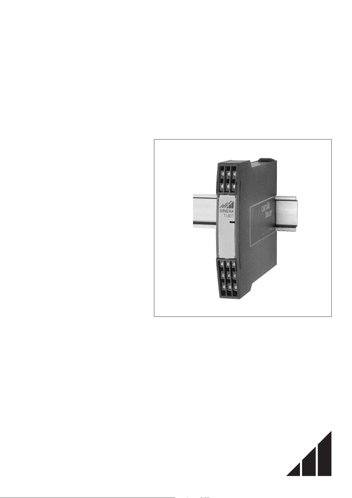
Passiver DC-Signaltrenner SINEAX TI 807-1
Mode d’emploi
Séparateur galvanique passif SINEAX TI 807-1
Operating Instructions
Passive DC signal isolator SINEAX TI 807-1
Camille Bauer AG
TI 807-1 B d-f-e 997 067 12.00
Aargauerstrasse 7
CH-5610 Wohlen/Switzerland
Phone +41 56 618 21 11
Fax +41 56 618 24 58
e-mail: cbag@gmc-instruments.com
http://www.gmc-instruments.com
GOSSEN
CAMILLE BAUER
METRAWATT
1
Page 2

2
Page 3
Betriebsanleitung
Passiver DC-Signaltrenner
SINEAX TI 807-1
Mode d’emploi
Séparateur galvanique passif
SINEAX TI 807-1
Operating Instructions
Passive DC signal isolator
SINEAX TI 807-1
Deutsch
Français
English
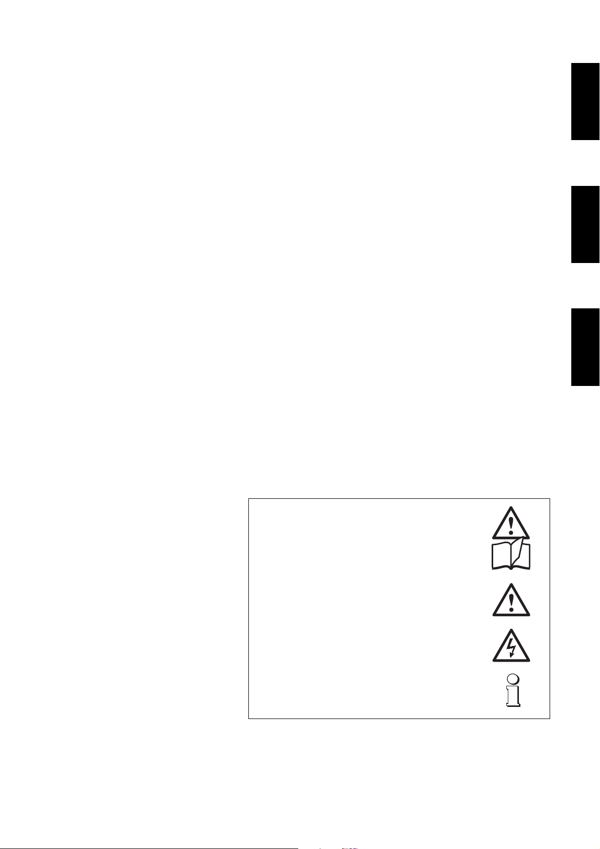
Sicherheitshinweise, die unbedingt beachtet werden müssen, sind in dieser Betriebsanleitung mit
folgenden Symbolen markiert:
Les conseils de sécurité qui doivent impérativement être observés sont marqués des symboles
ci-contre dans le présent mode d’emploi:
Safety precautions to be strictly observed are
marked with following symbols in the Operating
Instructions:
3
Page 4
Betriebsanleitung
Passiver DC-Signaltrenner SINEAX TI 807-1
Deutsch
Inhaltsverzeichnis
1. Erst lesen, dann... ...................................................... 4
2. Lieferumfang ............................................................... 4
3. Kurzbeschreibung ....................................................... 4
4. Aufschlüsselung der Varianten ................................... 4
5. Technische Daten ....................................................... 4
6. Frontschild austauschen ............................................. 5
7. Befestigung ................................................................. 5
8. Elektrische Anschlüsse ............................................... 6
9. Inbetriebnahme ........................................................... 7
10. Demontage-Hinweis ................................................... 7
11. Mass-Skizzen .............................................................. 7
1. Erst lesen, dann …
Der einwandfreie und gefahrlose Betrieb
setzt voraus, dass die Betriebsanleitung
gelesen und die in den Abschnitten
7. Befestigung
8. Elektrische Anschlüsse
enthaltenen Sicherheitshinweise beachtet
werden.
Der Umgang mit diesem Gerät sollte nur
durch entsprechend geschultes Personal
erfolgen, welches das Gerät kennt und berechtigt ist, Arbeiten in regeltechnischen
Anlagen auszuführen.
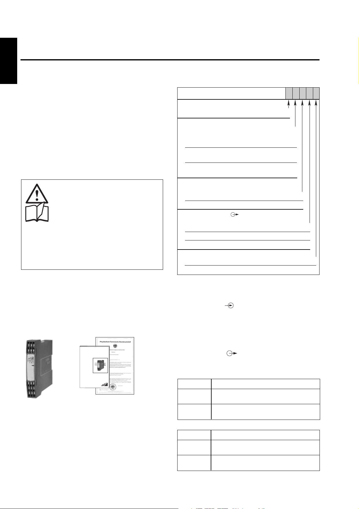
4. Aufschlüsselung der Varianten
Bestell-Code 807 –
1.Bauform
Gehäuse S17 1
2.Ausführung
Standard (Nicht Ex) 1
Ein- und Ausgangssignal
nicht eigensicher
[EEx ib] II C, 2
Eingangssignale eigensicher
[EEx ia] II C, 6
Ausgangssignale eigensicher
3.Anzahl der Trenn- und
Übertragungskanäle
2 Kanäle (Trennstellen) 2
3 Kanäle (Trennstellen) 3
4.Ausgangssignale
A1 und A2 oder A1, A2 und A3
0 ... 20 mA 0
0 ... 10 V, 2 Kanäle 2
0 … 10 V, 3 Kanäle 3
5.Klimatische Beanspruchung
Standard-Klimafestigkeit 0
Erhöhte Klimafestigkeit 1
2. Lieferumfang
Signaltrenner (Bild 1)
1 Betriebsanleitung (Bild 2), dreisprachig: Deutsch,
Französisch, Englisch
1 Ex-Bescheinigung (Bild 2), nur bei Geräten in Ex-
Ausführung
Betriebsanleitung
Passiver DC-Signaltrenner SINEAX TI 807
Mode d’emploi
Séparateur galvanique passif
SINEAX TI 807
Operating manual
Passive DC signal isolator SINEAX TI 807
TI 807-1 B d-f-e 999 999 12.95
Aargauerstrasse 7
CH-5610 Wohlen/Switzerland
Telefon +41 56 618 2111
Telefax +41 56 618 24 58
Telex 827 901 cbm ch
Camille Bauer AG
Bild 1
Bild 2
3. Kurzbeschreibung
Der Signaltrenner SINEAX TI 807 dient zur Galvanischen
Trennung von zwei oder drei analogen Gleichstromsignalen
0...20 mA, die – je nach Geräte-Ausführung – in Strom- oder
Spannungssignale (0...20 mA oder 0...10 V) übertragen werden. Er arbeitet ohne separat zugeführte Hilfsenergie.
5. Technische Daten
Eingangssignal E
Gleichstromsignal IE: 0...20 mA
Max. zulässiger Strom: 50 mA
Spannungsbegrenzung: Nicht-Ex-Ausführung: 27 V, ±5%
(mit Zenerdiode)
Ex-Ausführung: 18 V, ±5%
Ausgangssignal A
(Gleichstrom oder Gleichspannung)
Gleichstromsignal IA: 0...20 mA
Spannungsabfall U
< 2,6 V bei der Standard- (Nicht Ex-) Ausführung
< 4,5 V bei Ex-Ausführungen
< 6,1 V bei Ex-Ausführungen
Max. Bürde:
1000 Ω bei der Standard- (Nicht Ex-) Ausführung
500 Ω bei Ex-Ausführungen
500 Ω bei Ex-Ausführungen
:
V
(Eingangssignale «eigensicher»)
(Ausgangssignale «eigensicher»)
(Eingangssignale «eigensicher»)
(Ausgangssignale «eigensicher»)
4
Page 5
Begrenzung: Ca. 40 mA
G
O
S
S
E
N
M
E
T
R
A
WAT
T
CA
M
IL
L
E
B
A
U
E
R
G
O
S
S
E
N
M
E
T
R
A
WAT
T
CA
M
IL
L
E
B
A
U
E
R
O
N
G
O
S
S
E
N
M
E
T
R
A
WAT
T
CA
M
IL
L
E
B
A
U
E
R
G
O
S
S
E
N
M
E
T
R
A
WAT
T
CA
M
IL
L
E
B
A
U
E
R
Restwelligkeit: < 20 mV ss
Zeitkonstante: Ca. 3 ms
Einstellzeit
1
nach IEC 770: Ca. 15 ms
Gleichspannungssignal U
: 0...10 V
A
Spannungsabfall UV:
< 2,6 V bei der Standard- (Nicht Ex-) Ausführung
< 4,5 V bei Ex-Ausführungen
(Eingangssignale «eigensicher»)
< 6,1 V bei Ex-Ausführungen
(Ausgangssignale «eigensicher»)
Innenwiderstand: 500 Ω
Begrenzung:
< 26 V bei der Standard- (Nicht Ex-) Ausführung
< 16 V bei Ex-Ausführungen
(Eingangssignale «eigensicher»)
< 16 V bei Ex-Ausführungen
(Ausgangssignale «eigensicher»)
Restwelligkeit: < 20 mV ss
Zeitkonstante: Ca. 3 ms
Einstellzeit
1
nach IEC 770: Ca. 15 ms
S
I
N
E
A
S
I
N
E
A
X
T
I
8
0
7
O
N
(
X
T
I
8
0
7
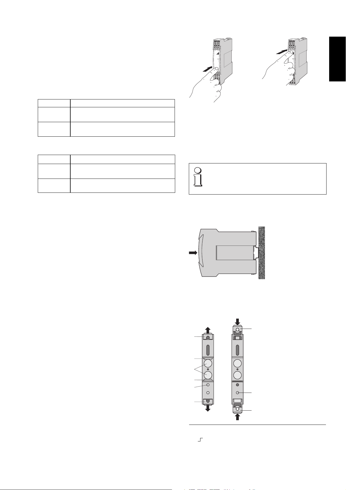
Bild 3. Links: Herausnehmen der Klarsichtabdeckung
Rechts: Einsetzen der Klarsichtabdeckung.
7. Befestigung
Die Befestigung des SINEAX TI 807 erfolgt wahlweise auf
einer Hutschiene oder direkt an einer Wand bzw. auf einer
Montagetafel.
Beachten, dass die Grenzen der Betriebstemperatur nicht überschritten werden:
– 25 und + 55 °C bei Standard-Geräten
–20 und + 55 °C bei Ex-Geräten!
7.1 Befestigung auf Hutschiene
Gehäuse auf Hutschiene (EN 50 022) aufschnappen (siehe
Bild 4).
Deutsch
Genauigkeitsangaben
Fehlergrenze: < ± 0,1%
2
(Bezugswert 20 mA,
Linearitätsfehler eingeschlossen)
< ± 0,2%
3
(Bezugswert 10 V,
Linearitätsfehler eingeschlossen)
Umgebungsbedingungen
Betriebstemperatur: – 25 bis + 55 °C,
–20 bis + 55 °C
(bei den Ex-Ausführungen: Ein- oder
Ausgangssignale «eigensicher»)
Lagerungstemperatur: – 40 bis + 70 °C
Relative Feuchte
im Jahresmittel: ≤ 75% Standard-Klimafestigkeit
≤ 95% Erhöhte Klimafestigkeit
Vibrationsfestigkeit: 5 g, < 200 Hz, je 2 h in 3 Richtungen
Schock: 50 g, je 10 Stösse in 3 Richtungen
6. Frontschild austauschen
Klarsichtabdeckung für Frontschild gemäss Bild 3, links, mit
Finger leicht eindrücken, bis sie auf der gegenüberliegenden
Seite herausspringt. Das eingelegte Frontschild ist austauschbar und steht zum Anbringen von Vermerken zur
Verfügung.
Nach dem Wiedereinlegen des Frontschildes in die Klarsichtabdeckung, diese wieder einsetzen. Dazu Klarsichtabdeckung
zuerst unter die untere Halterung führen und mit Finger
(Bild 3, rechts) durch Druck zum Einrasten bringen.
Bild 4. Montage auf
Hutschiene 35 ×15
oder 35 × 7,5 mm.
7.2 Befestigung auf Wand
Die Befestigungslaschen (1) lassen sich nach Drücken der
Entriegelung (4) herausziehen. Nach Drücken der Entriegelung
(5) lassen sie sich wieder zurückschieben.
(1)
(1)
(2)
(3)
(2)
(4)
(5)
(1)
(1)
1
Ist die Zeit, die vergeht, bis das Ausgangssignal die Fehlergrenze
von 1% erreicht hat bei einem Sprung des Eingangssignals von
0 90%.
2
Beim Stromsignal und RA = 250 Ω.
3
Beim Spannungssignal
Bild 5. Geräteboden.
(1) Befestigungslaschen
(2) Schnappverschlüsse
(3) Gummipuffer
(4) Entriegelung zum
Hausziehen der
Befestigungslaschen
(5) Entriegelung zum
Hineinschieben der
Befestigungslaschen
5
Page 6

Gehäuse an Wand oder Montagetafel mit 2 Schrauben
4 mm ∅ befestigen. Löcher nach Bohrplan (Bild 6) bohren.
Deutsch
120
Bild 6. Bohrplan.
... dass die Leitungen des Ein- und Ausgangs-
signals als verdrillte Kabel und möglichst
räumlich getrennt von Starkstromleitungen
verlegt werden!
Leitungen der Eingangssignale E1 … E3 und der Ausgangssignale A1 … A3 je nach Geräte-Ausführung (Typ) nach
Bilder 7 bis 10 anschliessen.
Signaltrenner im Gehäuse S17 mit zwei Trenn- und
Übertragungskanälen
8. Elektrische Anschlüsse
Zum Anschliessen der elektrischen Leitungen dienen
Schraubklemmen, die gut zugänglich in der Frontpartie des
Signaltrenners untergebracht sind (vgl. Bilder 7 bis 10) und
sich für Drahtquerschnitte bis max. 2,5 mm2 eignen.
Unbedingt sicher stellen, dass die Messeingangsleitungen beim Anschliessen
spannungsfrei sind!
Bei Geräten in der Zündschutzart «Eigen-
sicherheit» [EEx ib ] IIC oder [EEx ia] IIC sind
zusätzlich die Angaben der Baumusterprüfbescheinigung, die EN 60 079-14, sowie die
nationalen Vorschriften für die Errichtung
von elektrischen Anlagen in explosionsgefährdeten Bereichen zu berücksichtigen.
Es ist zu beachten, ...
... dass die Daten, die zur Lösung der Trenn-
und Übertragungsaufgabe erforderlich sind,
mit denen auf dem Typenschild des SINEAX
TI 807 übereinstimmen (
und Ausgangssignale)!
... dass – beim Signaltrenner mit Stromaus-
gang 0...20 mA – der Gesamtwiderstand in
der Ausgangssignal-Leitung (in Serie geschaltete Empfangsgeräte plus Leitung) die
max. Bürde von 1000 Ω bei der StandardAusführung und 500 Ω bei der Ex-Ausführung nicht überschreitet! Vgl. «Ausgangssignal», Abschnitt «5. Technische Daten»!
... dass – beim Signaltrenner mit Spannungs-
ausgang 0...10 V – die in der Ausgangssignal-Leitung parallel vorzusehenden Empfangs-Geräte einen hohen Innenwiderstand
RiA aufweisen; «hoch» in Relation zum Innenwiderstand des SINEAX TI 807 von 500 Ω!
Vgl. «Ausgangssignal», Abschnitt «5. Technische Daten»!
Der von RiA abhängige Fehler beträgt:
F [%] =
500 [Ω] · 100
A [Ω]
Ri
Eingangssignale
1
6
27
8
3
9
4
1
6
27
8
3
9
4
–
+
+
+
A1
A2
–
–
+
+
–
–
+
+
+
–
–
–
+
E1
E2
E1
E2
A1
Bild 7.
Typ 807-112…,
Standard-(Nicht Ex-)
Ausführung
und
Typ 807-162…,
Ex-Ausführung
(Ausgangssignale A1
und A2 «eigensicher»)
+
A2
–
Bild 8.
Typ 807-122…,
Ex-Ausführung
(Eingangssignale E1
und E2 «eigensicher»)
6
Page 7

Signaltrenner im Gehäuse S17 mit drei Trenn- und
Übertragungskanälen
–
+
–
+
1
11
6
+
+
A1
A2
A3
12
27
–
10. Demontage-Hinweis
Messumformer gemäss Bild 11 von der Tragschiene abnehmen.
Deutsch
Bild 11
8
3
9
4
1
6
27
8
3
9
4
–
+
–
+
13
+
14
–
–
+
–
+
11
+
+
12
–
–
+
–
+
13
+
14
–
E1
E2
E3
E1
E2
E3
A1
A2
A3
Bild 9.
Typ 807-113…,
Standard-(Nicht Ex-)
Ausführung
und
Typ 807-163…,
Ex-Ausführung
(Ausgangssignale
A1, A2 und A3
«eigensicher»)
Bild 10.
Typ 807-123…,
Ex-Ausführung
(Eingangssignale
E1, E2 und E2
«eigensicher»)
11. Mass-Skizzen
120
+0.5
+0
Bild 12. SINEAX TI 807-1 im Gehäuse S17 auf Hutschiene
(35 ×15 mm oder 35 × 7,5 mm, nach EN 50 022) aufgeschnappt.
134
6,5
Ø4,5
120
14
120
146.517.5
9. Inbetriebnahme
Zur Inbetriebnahme einfach die Eingangssignale E1 … E3
einschalten.
Der Signaltrenner ist wartungsfrei.
17,5
+0
Bild 13. SINEAX TI 807-1 im Gehäuse S17 mit herausgezogenen
Laschen für direkte Wandmontage.
145,5
12
+0,5
7
Page 8

Mode d’emploi
Séparateur galvanique passif SINEAX TI 807-1
Sommaire
1. A lire en premier, ensuite... ........................................ 8
2. Etendue de la livraison ................................................ 8
3. Description brève ........................................................ 8
4. Codage des variantes ................................................. 8
5. Caractéristiques techniques ....................................... 8
6. Changement de la plaquette frontale ......................... 9
7. Fixation ....................................................................... 9
8. Raccordements électriques ...................................... 10
9. Mise en service et entretien ...................................... 11
10. Instructions pour le démontage ................................ 11
Français
11. Croquis d’encombrements ....................................... 11
1. A lire en premier, ensuite …
Pour un fonctionnement sûr et sans danger,
il est essentiel de lire le présent mode
d’emploi et de respecter les recommanda-
tions de sécurité mentionnées dans les
rubriques
7. Fixation
8. Raccordements électriques.
Ces appareils devraient uniquement être
manipulés par des personnes qui les
connaissent et qui sont autorisées à travailler
sur des installations techniques du réglage.
4. Codage des variantes
Code de cde 807 –
1.Construction
Boîtier S17 1
2.Exécution
Standard (non-Ex) 1
Entrée et sortie
non en sécurité intrinsèque
[EEx ib] II C, 2
Entrée en sécurité intrinsèque
[EEx ia] II C, 6
Sortie en sécurité intrinsèque
3.Nombre des canaux de séparation
et de transmission
2 circuits de séparation 2
3 circuits de séparation 3
4.Signal de sortie
A1 et A2 ou A1, A2 et A3
0 ... 20 mA 0
0 ... 10 V, 2 canaux 2
0 … 10 V, 3 canaux 3
5.Sollicitations climatiques
Sollicitations climatiques standard 0
Sollicitations climatiques accrues 1
2. Etendue de la livraison
Séparateur galvanique (Fig. 1)
1 Mode d’emploi (Fig. 2), en trois langues: français,
allemand et anglais
1 Attestation Ex (Fig. 2), seulement pour appareils en
version Ex
Betriebsanleitung
Passiver DC-Signaltrenner SINEAX TI 807
Mode d’emploi
Séparateur galvanique passif
SINEAX TI 807
Operating manual
Passive DC signal isolator SINEAX TI 807
TI 807-1 B d-f-e 999 999 12.95
Aargauerstrasse 7
CH-5610 Wohlen/Switzerland
Telefon +41 56 618 2111
Telefax +41 56 618 24 58
Telex 827 901 cbm ch
Camille Bauer AG
Fig. 1
Fig. 2
3. Description brève
Le séparateur galvanique SINEAX TI 807 sert à la séparation
galvanique de deux ou trois signaux de courant continu
analogique 0…20 mA qui est retransmis – suivant le modèle
choisi – sous forme d’un courant continu ou d’une tension
continue (0...20 mA ou 0...10 V). Il fonctionne sans alimentation
auxiliaire.
5. Caractéristiques techniques
Signal d’entrée E
Signal courant
continu IE: 0...20 mA
Courant max.: 50 mA
Limitation de tension: Exécution non-Ex: 27 V, ±5%
(par diode zener)
Exécution Ex: 18 V, ±5%
Signal de sortie A
(Courant continu ou tension continue)
Sortie en courant
continu IA: 0...20 mA
Chute de tension UV:
< 2,6 V pour l’exécution standard (non-Ex)
< 4,5 V pour les exécutions Ex
(entrées en «sécurité intrinsèque»)
< 6,1 V pour les exécutions Ex
(sorties en «sécurité intrinsèque»)
Charge max.:
1000 Ω pour l’exécution standard (non-Ex)
500 Ω pour les exécutions Ex
(entrées en «sécurité intrinsèque»)
500 Ω pour les exécutions Ex
(sorties en «sécurité intrinsèque»)
8
Page 9

Limitation: Env. 40 mA
G
O
S
S
E
N
M
E
T
R
A
WAT
T
CA
M
IL
L
E
B
A
U
E
R
G
O
S
S
E
N
M
E
T
R
A
WAT
T
CA
M
IL
L
E
B
A
U
E
R
O
N
G
O
S
S
E
N
M
E
T
R
A
WAT
T
CA
M
IL
L
E
B
A
U
E
R
G
O
S
S
E
N
M
E
T
R
A
WAT
T
CA
M
IL
L
E
B
A
U
E
R
Ondulation résiduelle: < 20 mV ss
Constante de temps: Env. 3 ms
Temps de réponse
1
selon CEI 770: Env. 15 ms
Sortie en tension
continue U
Chute de tension U
: 0...10 V
A
:
V
< 2,6 V pour l’exécution standard (non-Ex)
< 4,5 V pour les exécutions Ex
(entrées en «sécurité intrinsèque»)
< 6,1 V pour les exécutions Ex
(sorties en «sécurité intrinsèque»)
Résistance interne: 500 Ω
Limitation:
< 26 V pour l’exécution standard (non-Ex)
< 16 V pour les exécutions Ex
(entrées en «eigensicher»)
< 16 V pour les exécutions Ex
(sorties en «sécurité intrinsèque»)
Ondulation résiduelle: < 20 mV ss
Constante de temps: Env. 3 ms
Temps de réponse
1
selon CEI 770: Env. 15 ms
S
S
IN
E
A
X
T
I
8
0
7
O
N
(
IN
E
A
X
T
I 8
0
7
Fig. 3. A gauche: Enlever le capot transparent
A droite: Remettre en place le capot transparent.
7. Fixation
Les SINEAX TI 807 peuvent être au choix montés sur des rails
symétrique «en chapeau» ou directement sur une paroi ou
sur un tableau.
Il faut faire attention que les valeurs limites de la
température de fonctionnement ne soient pas
dépassées:
– 25 et + 55 °C pour appareils standard
–20 et + 55 °C pour appareil en exécution Ex!
7.1 Montage sur rail symétrique «en chapeau»
Encliqueter le boîtier sur le rail symétrique «en chapeau»
(EN 50 022) (voir Fig. 4).
Français
Indications concernant la précision
Limite d’erreur: < ± 0,1%
2
(val. de référence 20 mA à la sortie,
erreur type de linéarité comprise)
< ± 0,2%
3
(val. de référence 10 V à la sortie,
erreur type de linéarité comprise)
Ambiance extérieure
Température de
fonctionnement: – 25 à + 55 °C,
–20 à + 55 °C
(pour les exécutions Ex: Entrée ou
sortie en «sécurité intrinsèque»)
Temp. de stockage: – 40 à + 70 °C
Humidité relative
en moyenne annuelle: ≤ 75% classe climatique standard
≤ 95% classe climatique accrue
Résist. aux vibrations: 5 g, < 200 Hz,
pendant 2 h dans 3 directions
Schock: 50 g,
10 chocs dans 3 directions
6. Changement de la plaquette frontale
Faire une légère pression sur le capot transparent (Fig. 3 à
gauche) jusqu’à ce qu’il se libère en haut. La plaquette
signalétique est interchangeable et sert à des annotations
diverses. Après mise en place de la plaquette, remettre le
capot transparent en le glissant d’abord dans la gorge
inférieure et l’encliqueter définitivement par une pression du
doigt (Fig. 3 à droite).
Fig. 4. Montage sur
rail symétrique «en
chapeau» 35 × 15
ou 35 × 7,5 mm.
7.2 Montage sur paroi
Tirer en dehors les languettes de fixation (1) en enfonçant en
même temps le bouton de verrouillage (4) (voir Fig. 5 à
gauche). Pour rentrer si nécessaire les languettes de fixation,
il faut enfoncer le bouton de verrouillage (5) et en même
temps glisser les languettes de fixation (1) dans la base du
boîtier (voir Fig. 5 à droite).
(1)
(1)
(2)
(3)
(2)
(4)
(5)
(1)
(1)
1
Le temps qui s’écoule jusqu’à ce que le signal de sortie ait atteint,
en restant dans la tolérance d’erreur de 1% la nouvelle valeur
après un sauf indiciel du signal d’entrée de 0 90%.
2
Pour signal courant et RA = 250 Ω.
3
Pour signal tension
Fig. 5. Fond de l’appareil.
(1) Languettes de fixation
(2) Cliquets de retenue
(3) Tampons en
caoutchouc
(4) Verrouillage pour
languettes rentrées
(5) Verrouillage pour
languettes extraites
9
Page 10

Fixer le boîtier à l’aide de 2 vis 4 mm ∅ sur la paroi ou sur le
tableau de montage. Perçer des trous selon le plan de
perçage (Fig. 6).
0
2
1
Fig. 6. Plan de perçage.
Français
8. Raccordements électriques
Les lignes électriques sont raccordée à l’aide de bornes à vis
aisément accessibles et logées dans la partie frontale (voir
Fig. 7 à 10). Elles sont prévues pour des sections de fils de
max. 2,5 mm2.
Lors du raccordement des câbles, s’assurer
impérativement que les lignes des signaux
d’entrée soient hors tension!
... que les lignes d’entrée et de sortie de signal
de mesure soient réalisées par des câbles
torsadés et disposées à une certaine
distance des lignes courant fort!
Raccorder les lignes des signaux d’entrée E1 … E3 et de
sortie A1 … A3 selon Figs. 7 à 10.
Séparateur galvanique en boîtier S17 avec deux
circuits de séparation galvanique
–
+
1
6
+
+
A1
A2
27
–
Pour les appareils en mode de protection
«à sécurité intrinsèque» [EEx ib ] IIC ou
[EEx ia] IIC il faut respecter les indications
contenues dans le certificat d’essai du
modèle type, l’EN 60 079-14, ainsi que les
prescriptions nationales pour la réalisation
d’installations électriques dans des
enceintes avec danger d’explosions.
Veiller en plus, ...
... que les caractéristiques techniques des
circuits à séparer correspondent aux
caractéristiques mentionnées sur la
plaquette signalétique des SINEAX TI 807
signaux d’entrée et signaux de
(
sortie)!
... que – pour le séparateur avec sortie courant
0...20 mA – la résistance totale du circuit de
sortie (instruments récepteurs connectés
en série plus résistance des lignes) n’excède
pas la charge de 1000 Ω (pour l’exécution
non-Ex) ou 500 Ω (pour l’exécution Ex)! Voir
«Signal de sortie», chapitre «5. Caractéristiques techniques»!
... que – pour le séparateur avec sortie tension
0...10 V – les appareils récepteurs connectés
en parallèle aient une résistance interne RiA
élevée, «élevée» par rapport à la résistance
interne de 500 Ω du SINEAX TI 807! Voir
«Signal de sortie», chapitre «5.
Caractéristiques techniques»!
L’erreur due à Ri
F [%] =
A se détermine comme suit:
500 [Ω] · 100
RiA [Ω]
8
3
9
4
1
6
27
8
3
9
4
–
+
E1
+
E2
–
–
+
+
+
E1
Fig. 7.
Type 807-112…,
exécution standard
(non-Ex)
et
Type 807-162…,
exécution Ex
(Sorties A1 et A2
«sécurité intrinsèque»)
E2
–
–
–
+
A1
+
A2
–
Fig. 8.
Type 807-122…,
exécution Ex
(Entrées E1 et E2
«sécurité intrinsèque»)
10
Page 11

Séparateur galvanique en boîtier S17 avec trois
146.517.5
120
+0.5
+0
circuits de séparation galvanique
–
+
–
+
1
11
6
+
+
A1
A2
A3
12
27
–
10. Instructions pour le démontage
Démonter le séparateur galvanique du rail support selon
Fig. 11.
8
3
9
4
1
6
27
Fig. 11
–
+
–
+
13
+
14
–
–
+
–
+
11
+
+
E1
Fig. 9.
Type 807-113…,
E2
exécution standard
(non-Ex)
et
E3
Type 807-163…,
exécution Ex
(Sorties
A1, A2 et A3
«sécurité intrinsèque»)
E1
E2
11. Croquis d’encombrements
Français
E3
12
–
Fig. 12. SINEAX TI 807-1 (boîtier S17) encliqueté sur rail
symétrique «en chapeau» (35 ×15 mm ou 35 × 7,5 mm, selon
EN 50 022).
–
+
–
+
8
13
3
4
+
9
14
–
A1
A2
Fig. 10.
A3
Type 807-123…,
exécution Ex
(Entrées
E1, E2 et E2
«sécurité intrinsèque»)
9. Mise en service et entretien
Pour la mise en service, il suffit d’enclencher les signaux
d’entrée E1 … E3.
Le séparateur galvanique ne nécessite pas d’entretien.
134
6,5
Ø4,5
120
12
+0,5
+0
145,5
14
120
17,5
Fig. 13. SINEAX TI 807-1 (boîtier S17) avec languettes extraites
pour montage mural.
11
Page 12

Operating Instructions
Passive DC signal isolator SINEAX TI 807-1
Contents
1. Read first and then................................................... 12
2. Scope of supply ........................................................ 12
3. Brief description ........................................................ 12
4. Specification and ordering information ..................... 12
5. Technical data........................................................... 12
6. Exchanging frontplates ............................................. 13
7. Mounting ................................................................... 13
8. Electrical connections ............................................... 14
9. Commissioning and maintenance ............................ 15
10. Releasing the signal isolator ..................................... 15
11. Dimensional drawings ............................................... 15
1. Read first and then …
The proper and safe operation of the device
assumes that the Operating Instructions are
read carefully and the safety warnings given
in the Sections
7. Mounting
English
8. Electrical connections
are observed.
The device should only be handled by
appropriately trained personnel who are
familiar with it and authorised to work in
electrical installations.
4. Specification and ordering information
Order Code 807 –
1.Mechanical design
Housing S17 1
2.Version
Standard (non-Ex) 1
Input and output signals
non-intrinsically safe
[EEx ib] II C, 2
Input signals intrinsically safe
[EEx ia] II C, 6
Output signals intrinsically safe
3.Number of isolation
and transmission channels
2 channels (interfaces) 2
3 channels (interfaces) 3
4.Output signals
A1 and A2 or A1, A2 and A3
0 ... 20 mA 0
0 ... 10 V, 2 channels 2
0 … 10 V, 3 channels 3
5.Climatic rating
Standard climatic rating 0
Improved climatic rating 1
2. Scope of supply
Signal isolator (Fig. 1)
1 Operating Instructions (Fig. 2), in three languages:
English, French and German
1 Ex approval (Fig. 2), only for Ex version devices
Betriebsanleitung
Passiver DC-Signaltrenner SINEAX TI 807
Mode d’emploi
Séparateur galvanique passif
SINEAX TI 807
Operating manual
Passive DC signal isolator SINEAX TI 807
TI 807-1 B d-f-e 999 999 12.95
Aargauerstrasse 7
CH-5610 Wohlen/Switzerland
Telefon +41 56 618 2111
Telefax +41 56 618 24 58
Telex 827 901 cbm ch
Camille Bauer AG
Fig. 1
Fig. 2
3. Brief description
The signal isolator SINEAX TI 807 serves to electrically
insulate two or three analogue DC signals in the range
0...20 mA which depending on version is then converted to
a current or voltage signal (0...20 mA or 0...10 V). It does not
require a separate power supply.
5. Technical data
Input signal E
DC current signal IE: 0...20 mA
Max. permissible
currnet: 50 mA
Voltage limiter: Non-Ex version: 27 V, ±5%
(with zener diode)
Ex version: 18 V, ±5%
Output signal A
(DC current or DC voltage)
DC current signal IA: 0...20 mA
Voltage drop UV:
< 2.6 V for the standard (non-Ex) version
< 4.5 V for Ex versions
(input signals “intrinsically safe”)
< 6.1 V for Ex versions
(output signals “intrinsically safe”)
Max. burden:
1000 Ω for the standard (non-Ex) version
500 Ω for Ex versions
(input signals “intrinsically safe”)
500 Ω for Ex versions
(output signals “intrinsically safe”)
12
Page 13

Limit: Approx. 40 mA
G
O
S
S
E
N
M
E
T
R
A
WAT
T
CA
M
IL
L
E
B
A
U
E
R
G
O
S
S
E
N
M
E
T
R
A
WAT
T
CA
M
IL
L
E
B
A
U
E
R
O
N
G
O
S
S
E
N
M
E
T
R
A
WAT
T
CA
M
IL
L
E
B
A
U
E
R
G
O
S
S
E
N
M
E
T
R
A
WAT
T
CA
M
IL
L
E
B
A
U
E
R
Residual ripple: < 20 mV ss
Time constant: Approx. 3 ms
Response time
1
acc. to IEC 770: Approx. 15 ms
S
S
IN
E
A
X
T
I
8
0
7
O
N
(
IN
E
A
X
T
I 8
0
7
:
V
: 0...10 V
A
DC voltage signal U
Voltage drop U
< 2.6 V for the standard (non-Ex) version
< 4.5 V for Ex versions
(input signals “intrinsically safe”)
< 6.1 V for Ex versions
(output signals “intrinsically safe”)
Internal resistance: 500 Ω
Limit:
< 26 V for the standard (non-Ex) version
< 16 V for Ex versions
(input signals “intrinsically safe”)
< 16 V for Ex versions
(output signals “intrinsically safe”)
Residual ripple: < 20 mV ss
Time constant: Approx. 3 ms
Response time
1
acc. to IEC 770: Approx. 15 ms
Accuracy data
Error limits: < ± 0.1%
2
(Reference value 20 mA including
linearity error)
< ± 0.2%
3
(Reference value 10 V including
linearity error)
Ambient conditions
Operating temperature: – 25 to + 55 °C,
–20 to + 55 °C
(Ex versions: input or output signals
“intrinsically safe”)
Storage temperature: – 40 to + 70 °C
Annual mean
relative humidity: ≤ 75% standard climatic rating
≤ 95% improved climatic rating
Seismic test: 5 g, < 200 Hz,
2 h in each of 3 directions
Shock: 50 g,
10 shocks in each of 3 directions
6. Exchanging frontplates
Apply gentle pressure to the transparent cover as shown in
Fig. 3 (left) until it pops out on the opposite side. The label in
the cover can be replaced and used for notes.
After replacing the label in the transparent cover, the transparent cover can be snapped into the front of the device
again. This is done by inserting it behind the edge at the
bottom and pressing it gently down and to the rear with the
finger until it snaps into place (right side of Fig. 3).
Fig. 3. Left: Removing the transparent cover
Right: Inserting the transparent cover.
7. Mounting
The SINEAX TI 807 can be mounted either on a top-hat rail or
directly onto a wall or mounting plate.
Make sure that the ambient temperature stays
within the permissible limits:
– 25 and + 55 °C for standard instruments
–20 and + 55 °C for instruments in Ex version!
7.1 Top-hat rail mounting
Simply clip the device onto the top-hat rail (EN 50 022) (see
Fig. 4).
Fig. 4. Mounting on
top-hat rail 35 ×15
or 35 ×7.5 mm.
7.2 Wall mounting
While pressing the latch (4) in the base of the device (Fig. 5,
left) pull out the transmitter securing brackets (1). To return
the brackets to their original positions, the latch (5) in the
base of the device has to be depressed before applying
pressure to the securing brackets (1) (see Fig. 5, right).
(1)
(1)
(2)
(3)
(2)
(4)
(5)
(1)
(1)
1
This is the time which transpires before the output signal reaches
the error limit of 1% for a step change of the input signal from
0 90%.
2
With current signal and RA = 250 Ω.
3
With voltage signal
Fig. 5. Rear of device.
(1) Screw hole brackets
(2) Top-hat rail clip
(3) Rubber buffers
(4) Latch for pulling
the screw hole
brackets out
(5) Latch for pushing
the screw hole
brackets in
English
13
Page 14

Drill 2 holes in the wall or panel as shown in the drilling pattern
(Fig. 6). Now secure the signal isolator to the wall or panel
using two 4 mm diameter screws.
0
2
1
Fig. 6. Drilling pattern.
... the input and output cables should be twisted
pairs and run as far as possible away from
heavy current cables!
Connect the input and output leads E1 … E3 and A1 … A3
according to Figures 7 to 10.
Signal isolator in housing S17 with two isolation
and transmission channels
8. Electrical connections
The electrical connections are made to screw terminals
which are easily accessible from the front of the signal
isolator (see Figs. 7 to 10) and can accommodate wire
gauges up to 2.5 mm2.
English
Make sure that the cables are not live when
making the connections!
In the case of “intrinsically safe” explosion
proof versions [EEx ib ] IIC or [EEx ia] IIC, the
supplementary information given on the type
examination certification, the EN 60 079-14
and also local regulations applicable to
electrical installations in explosion hazard
areas must be taken into account.
Note that, ...
... the required electrical insulation and
transmission data agree with the data on
the nameplate of the SINEAX TI 807 (
input signals and output signals)!
... in the case of a signal isolator with current
outputs 0...20 mA, the total resistance of the
external leads (receiver plus leads) does
not exceed the maximum burden of 1000 Ω
(non-Ex version) or 500 Ω (Ex version)! See
“Output signal” in Section “5. Technical
data”!
... in the case of a signal isolator with voltage
output 0...10 V, the external receiver
connected across the output has a
sufficiently high internal resistance RiA in
relation to the SINEAX TI 807 output
impedance of 500 Ω! See “Output signal” in
Section “5. Technical data”!
The error due to RiA is:
F [%] =
500 [Ω] · 100
A [Ω]
Ri
1
6
27
8
3
9
4
1
6
27
8
3
9
4
–
+
+
+
A1
A2
–
–
+
+
–
–
+
+
+
–
–
–
+
E1
E2
E1
E2
A1
Fig 7.
Type 807-112…,
standard (non-Ex)
version
and
Type 807-162…,
Ex version
(output signals A1 and
A2 “intrinsically safe”)
+
A2
–
Fig. 8.
Type 807-122…,
Ex version
(input signals E1 and
E2 “intrinsically safe”)
14
Page 15

Signal isolator in housing S17 with three isolation
146.517.5
120
+0.5
+0
and transmission channels
–
+
–
+
1
11
6
+
+
A1
A2
A3
12
27
–
10. Releasing the signal isolator
Release the signal isolator from a top-hat rail as shown in
Fig. 11.
Fig. 11
8
3
9
4
1
6
27
8
3
9
4
–
+
–
+
13
+
14
–
–
+
–
+
11
+
+
E1
Fig. 9.
Type 807-113…,
E2
standard (non-Ex)
version
and
E3
Type 807-163…,
Ex version
(output signals
A1, A2 and A3
“intrinsically safe”)
E1
E2
11. Dimensional drawings
English
E3
12
–
Fig. 12. SINEAX TI 807-1 (housing S17) clipped onto a top-hat rail
(35 ×15 mm or 35 ×7.5 mm, acc. to EN 50 022).
–
+
–
+
13
+
14
–
A1
A2
Fig. 10.
A3
Type 807-123…,
Ex version
(input signals
E1, E2 and E2
“intrinsically safe”)
120
14
134
6.5
Ø4.5
120
9. Commissioning and maintenance
The device is in operation as soon as the input signals
E1 … E3 are connected.
The signal isolator requires no maintenance.
17.5
+0
Fig. 13. SINEAX TI 807-1 (housing S17) with the screw hole
mounting brackets pulled out.
145.5
12
+0,5
15
Page 16

16
 Loading...