

Page 1
3-349-887-03
1/1.17
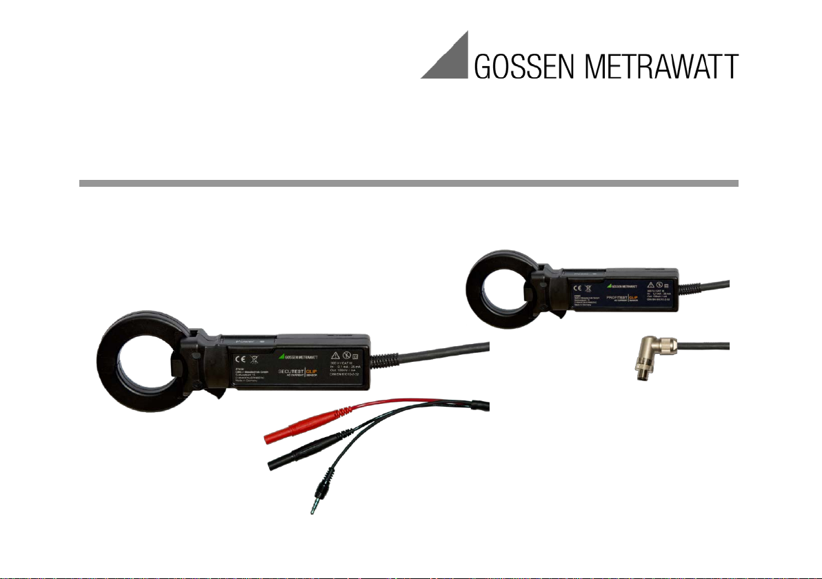
SECUTEST CLIP and PROFITEST CLIP
Leakage Current Clamp Meters for SECUTEST PRO and PROFITEST PRIME
Page 2

GMC-I Messtechnik GmbH
Notes Regarding these Operating Instructions
Texts, illustrations and technical specifications have been prepared with great
care. Errors can nevertheless not be entirely ruled out. The manufacturer of the
leakage current clamp meter cannot accept any legal responsibility or liability for
incorrect entries and their consequences!
Read these operating instructions carefully and co m pletely before using the
leakage current clamp meter!
Warnings and warning symbols in the operating instructions and on the leakage
current clamp meter are intended to alert the user to risks and hazards!
2
Page 3

GMC-I Messtechnik GmbH
Warnings and Safety Precautions
Read these operating instructions carefully and co m pletely before using the
necessary for safe operation and use of the leakage current clamp meter.
The SECUTEST CLIP / PROFITEST CLIP leakage current clamp meter has been
directives.
Safety of the operator, as well as that of the leakage current clamp meter, is only
assured when the device is used for its intended purpose.
The SECUTEST CLIP / PROFITEST CLIP leakage current clamp meter may only be
intended purpose (see also section 2, “Terminology” )!
leakage current clamp meter! They contain information and instructions which are
manufactured and tested in accordance with safety regulations
IEC 61557-13/-16, IEC 61010-1 and IEC 61010-2-032.
The CE conformity marking confirms com pliance with the EMC and low-voltage
used by electricians, other qualified persons or accordingly trained persons for its
3
Page 4
GMC-I Messtechnik GmbH
The following symbols draw the operator’s atte ntion to importa nt information and
instructions which are necessary for safe operation and use of the leakage current
clamp meter.
This symbol is used in the operating instructions in particular to
injury!
This symbol is used in the operating instructions and on the
uninsulated conductors.
This symbol is used in the operating instructions and on the
leakage current clamp meter in order to warn against incorrect
operation!
warn against risks and hazards associated with incorrect
operation!
Disregarding this warning symbol may result in severe or fatal
leakage current clamp meter in particular to warn against risks
and hazards associated with incorrect operation! Disregarding
this warning symbol may result in severe or fatal injury. During
use for its intended purpose, in consideration of the measuring
category, the leakage current clamp meter must not enclose any
4
Page 5
GMC-I Messtechnik GmbH
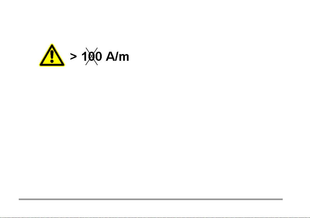
This warning symbol on the leakage
current clamp meter makes reference to
class 1.
sensitivity to external magnetic fields.
The field strength of the interfering
magnetic field may not exceed a value
of 100 A/m, which corresponds to use
5
Page 6

GMC-I Messtechnik GmbH
Opening the Instrument / Repairs
The instrument may only be opened by authorized, trained personnel in order to ensure
flawless operation and to assure that the guarantee is not rendered null and void.
Even original replacement parts may only be installed by authorized, trained personnel.
If it can be ascertaine d that t he instrument has bee n opened by unauthorized personnel, no
guarantee claims can be honored by the manufacturer with regard to personal safety,
measuring accuracy, compliance with applicable safety measures or any consequential
damages.
6
Page 7

GMC-I Messtechnik GmbH
Table of Contents
1
Applications ...................................................................................................................................... 8
2
Terminology ...................................................................................................................................... 8
3
Operation ......................................................................................................................................... 25
4
Connection Example s .................................................................................................................... 33
5
Calibration ....................................................................................................................................... 36
6
Care and M aintenance .................................................................................................................... 36
7
Guarantee ........................................................................................................................................ 37
8
Return and Environment al ly Sound Di spos al .............................................................................. 38
9
Technical Data ................................................................................................................................ 39
10 Product Support ............................................................................................................................. 44
11 Repair and Replacement Parts Service, Calibration Center and Rental Instrument Service .. 45
7
Page 8

GMC-I Messtechnik GmbH
1 Applications
When used for its intended purpose, the leakage current clamp
up to 600 V, e.g. at operating equipment.
Leakage Current Clamp Meter
A leakage current clamp meter is a current probe for the
1):2011, appendix A.
meter makes it possible to measure alternating current from 0.1 to
25 mA without interrupting any lines by closing the clamp around
one or more conductors in measuring category III electrical circuits
with up to 300 V between the phase conductor and gro und, e.g. in
build ing inst allations, or measuring category II electrical circuits with
2 Terminology
measurement of leakage current without interrupting the current
path of the measuring circuit. The meter must make it possible to
measure leakage current by means of the direct measuring method
or the differential current method.
The measurement results read out by the leakage current clamp
8
meter must take frequency response of test circuit A1 into
consideration in accordance with DIN EN 61010-1 (VDE 0411-
Page 9

GMC-I Messtechnik GmbH
Evaluation of frequency response is alrea d y taken into account by
the leakage current clamp meter.
Jaws
The components of the leakage current clamp meter which
enclose the conductor (see figure 3, item 1).
Yoke
The part of the leakage current clamp meter which is placed
field (see figure 3, item 2).
Use for Intended Purpose
The use for which the device is suitable in accordance with the
against operating the device under othe r than normal conditions.
around the conductor to be measured and detects the magnetic
manufacturer’s specifications (i.e. operating instructions).
Use for intended purpose also includes compliance with the
stipulated operating and maintenance conditions, as well as
consideration of foreseeable operating errors.
As a rule, normal conditions are a prerequisite for use for
intended purpose because the operating instructions warn
9
Page 10

GMC-I Messtechnik GmbH
Measuring Uncertainty
Measuring uncertainty is the specified difference between the
value displayed by the measuring instrument (measured va lue)
measured quantity in the operating range.
Intrinsic Uncertainty
Measuring error of a measuring instrument during operation
Electromagnetic Compatibility
All electrical currents generate electromagnetic fields which can
which also includes other equipment.
or the magnitude of the output signal and the actual value of the
under reference conditions.
cause current to f lo w in other electrical conductors, thus
resulting in interference. The European EMC directive for
electromagnetic compatibility (EN 61326-1) has been
implemented in order to avoid this interference or reduce it to an
absolute minimum.
Electromagnetic compatibility is the ability of a piece of electrical
equipment to function satisfactorily in its electromagnetic
environment without impermissibly influencing this environment,
10
Page 11
GMC-I Messtechnik GmbH
Stray Field Sensitivity
Influence error caused by a stray magnetic field which
determines the use class (DIN EN 60051-9).
Use Classes
Current probes are subdivided into 3 use classes based on
magnetic fields.
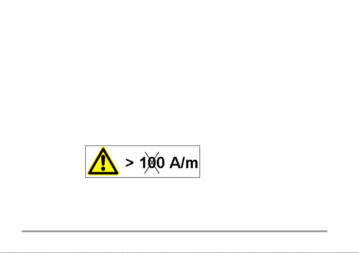
Strength of up to 100 A/m per Use Class 1
sensitivity to low-frequency magnetic fields with frequencies
ranging from 15 to 400 Hz. Current probes of all classes must be
furnished with a framed pictograph (see figure 1) which is plainly
visible to the operator, includes the corresponding symbol in
accordance with DIN EN 61010-1 (VDE 0411-1):2011 and warms
against exceeding the permissible limit value for external
Figure 1: Warning Symbol for Maximum Permissible Field
11
Page 12

GMC-I Messtechnik GmbH
Use Class 1
Use class 1 current probes must be suitable for use in external
low-frequency magnetic fields, in particular within a frequency
Use Class 2
Use class 2 current probes must be suitable for use in external
Use Class 3
Use class 3 current probes must be suitable for use in external
curren t cla m p meter by me a ns o f a pla inly vis ib l e warning s y m bo l.
range of 15 to 400 Hz, up to a field strength of 100 A/m. The
limit value for the magnetic field must be indicated on the
leakage current clamp meter by means of a plainly visible
warning symbol.
low-frequency magnetic fields, in particular within a frequency
range of 15 to 400 Hz, up to a field strength of 30 A/m. The limit
value for the magnetic field must be indicated on the leakage
current clamp meter by means of a plainly visible warning
symbol.
low-frequenc y ma g ne t ic f ie ld s , in par t ic ula r within a frequency
range of 15 to 400 Hz, up to a field strength of 10 A/m. The lim it
value for the magnetic field must be indicated on the leakage
12
Page 13

GMC-I Messtechnik GmbH
Electrician / Qualified Person / Trained Person
Only competent persons may use and conduct measurements
with leakage current clamp meters. In this sense, qualified
Electricians
An electrician is a person with suitable technical t raining,
01,
Qualified Persons
A qualified person is someone who posses the technical knowledge
Electrically Trained Persons
An electrically trained person is someone who has been
826-09-02, modified].
persons include:
knowledge and experience which makes it possible to recognize
and avoid the hazards associated with electricity [IEV 826-09modified].
required for testing equipment as a result of vocational training,
work experience and recent vocational activity [German
Occupational Safety Law (BetrSichV)]. Qualified persons are not
subject to any technical directives during the course of their
testing work and may not be disadvantaged by them.
adequately trained by a electric ian, thu s making it possible to
recognize and avoid the hazards associated with electricity [IEV
13
Page 14
GMC-I Messtechnik GmbH
Field Strength
Field strength designates the strength of and electrical,
Electrical Field Strength
The symbol for electrical field strength is E and its unit of
magnetic or other spatially distributed field at a specified point
in space. Field strength is frequently a vector and is calculated
on the basis of direction and magnitude. Well-known fields
include the
electrical field and the magnetic field.
measure is volts per meter (V/m). It increases along with
voltage U (V) between the charged bodies, and as distance L
(m) between the charged bodies is reduced.
E = U/L [V/m]
14
Page 15

GMC-I Messtechnik GmbH
Frequency Characteristics of the Human Body
Measuring setup for direct current and sinusoidal alternating
frequency range (below 1000 Hz).
current in accordance with IEC 61010-1, appendix A. This
measuring circuit (low-pass) prevents the measurement of
leakage current in the high-frequency range (as of roughly
1000 Hz). People react especia lly sensitively to the low-
15
Page 16

GMC-I Messtechnik GmbH
Calibration/Adjustment
What is calibration?
Calibration involves the determination of deviation of the
measuring instrument’s measured value / measurement signal
from the correct value of the measured quantity. An object with
known values (a so-called
standard) is measured by the device to
this end and deviation of the measured value / measurement
signal f r o m the known value is ascertained. The results and the
associated measuring uncertainty are documented in a ca libration
certificate.
No changes (adjustments) are made to the measuring equipment
during calibra t io n .
And thus calibration is simply the determination of the measured
value’s / measurement signal’s deviation from the true value.
What’s the purpose of calibration at regular intervals?
- It’s a requirement per DIN EN ISO 9000 ff.
- It prevents hazards due to incorrect measurement results.
- It assures reproducible measurement.
- It facilitates the acceptance of test reports and
measurement results.
16
Page 17

GMC-I Messtechnik GmbH
What is adjustment?
correc t v a lue . As a rule, ad ju s t ment is fo llowed by ca lib r a t ion.
Magnetic Field Strength
Every electrical current generates a magnetic field.
Measuring Categories
Measuring current circuits are subject to loading due to the
operating voltages and transient loads (overvoltage) in the circuits
In the field of measuring technology, adjustment involves
configuring or balancing a piece of measuring equipment
(measuring instrument, measuring adapter e tc.) such that the
measured or displayed value deviates as little as po ssible fr om the
The greater the amperage, the larger the magnetic field.
The symbol for magnetic field strength is H and its
measure is amperes per meter (A/m). Where magnetomotive
force (θ) remains unchanged, field strength increases as field line
length L (m) is reduced.
H = θ/L [A/m]
unit of
17
Page 18

GMC-I Messtechnik GmbH
to which they are connected. If the measuring curre nt circuit is
used to conduct a measurement at the mains, the transient loads
Figure 2: Measuring Categories
can be assessed via the location within the installation at w hich
the measurement is conducted. If the measuring current circuit is
used to measure any other signal, the transient loads must be
taken into consideration by the user such that they don’t exceed
the cap a b il ities and limitatio n s o f t h e me as u ring instr u m ent.
Electr ical circuits are s u bd iv id e d in t o t h e fo llo w ing measuring
categories: CAT I, CAT II, CAT III and CAT IV. The measuring
instrument may only be used in the category for which it has been
approved, or any lower categories.
18
Page 19

GMC-I Messtechnik GmbH
Examples:
CAT I:
- Battery powered devices
- Overhead power lines, underground cables
- Devices with electrical circuits which are internally
protected against overvoltage
- Circuits which are isolated from the mains
- Electronic circuits with corresponding power supply
CAT II:
- Household appliances
- Operating equipment
- Switches, lamps, electrical outlets e tc. in buildings
CAT III:
- Meters, control panels, test panels
- Machines
- High power operating equipment
CAT IV:
- Power lines used to feed buildings
19
Page 20

GMC-I Messtechnik GmbH
Measuring Category I (CAT I)
Measuring category I is intended for measurements in electrical
circuits which are not directly connected to the mains. Only
measurements at circuits which do not originate from the mains.
Measuring Category II (CAT II)
Measuring category II is intended for measurements in electrical
portable tools and similar devices.
Measuring Category III (CAT III)
Measuring category III is intended for measurements in building
installa tions. Conside r a ble overv o lt a ge can occur in these circuits.
Measuring Category IV (CAT IV)
Measuring category IV is intended for measurements at power
occur in these circuits.
minimal o vervoltage can occur in these circuits. Examples include
circuits which are directly connected to the low-voltage mains.
Overvoltage can occur in these circuits.
Examples include measurements at household appliances,
sources for low-voltage installations. Very high overvoltage can
20
Page 21

GMC-I Messtechnik GmbH
Reference Conditions
Influencing quantities for whose prese nce the measuring
instrument’s smallest specified or ascertained measuring
uncertainties (measuring error) apply.
Protection
In accordance with IEC 364-5-51 (VDE 0100, part510), the
assured.
Protection against foreign matter and dust
None IP0X
No dust ingress = IP6X
characteristic features of the respective operating equipment
must be determined by means of a protection class or a
conformity test.
Electrical operating equipment must be selected and set up in
consideration of external influences such that its intended
operation and the reliability of the protective measures are
Foreign matter > 50 mm = IP1X
Foreign matter > 12 mm = IP2X
Foreign matter > 2.5 mm = IP3X
Foreign matter > 1 mm = IP4X
No dust deposits = IP5X
21
Page 22

GMC-I Messtechnik GmbH
Protection against moisture
None IPX0
Vertically dripping = IPX1
Continuous submersion ( water pressure-tight) = IPX8
Protection Categories
Options for classifying electrical devices according to type of
connected to an electrical system.
Protection Category I
Devices with a protective conductor. The protective measure
conductor to the protective conductor of the electrical power
Dripping (15° angle) = IPX2
Spraying water = IPX3
Splashing water = IPX4
Water jets = IPX5
Powerful water jets = IPX6
Occasional submersion (water-proof) = IPX7
protective measure against electric shock, which becomes active
for them with priority or can become active after they are
against electric shock is based on connection of the protective
22
Page 23

GMC-I Messtechnik GmbH
supply system. All exposed, conductive par ts are connected to
the protective conductor as a rule. However, if any exposed,
implemented as protective measures against electric shock.
Protection Category II
Devices whose active parts are f u lly enclose d by an in s u la t in g
device ’ s in te rior, in c lud i n g t erminals, solder po st s an d t h e like.
Protection Category III
Devices for which exclusively protective extra-low voltag e is u se d.
conductive parts are not connected to the protective conductor,
doubled/reinforced insulation (protective insulation) or reliable
current limiting between such parts and the active parts must be
sleeve ( insulating b o d y wit h d o u ble or reinforced insulation). This
sleeve (body) ensures protection against electric shock for
persons who touch it.
The body also includes any exposed, conductive parts.
Protection category II devices can also have a connector plug with
earthing contact and a protective conductor in the connector
cable, which nevertheless may not be connected to any part in the
23
Page 24

GMC-I Messtechnik GmbH
Pollution Degree
Pollution involves the accumulation of solid, liquid or gaseous
(ionized gases) foreign matter, which can result in reduced
Pollution Degree 1
No pollution, or strictly dry, non-conductive pollution occurs. This
Pollution Degree 2
Usually only non-conductive pollution occurs. Occasional,
Pollution Degree 3
Conductive pollution accumulates or dry, no n -conductive
sites , in hea vy industry, in maritime applications etc.
dielectric strength or surface resistance. Pollution degrees have
been established for the ascertainment of clearances:
pollution has no impact.
temporary conductivity must nevertheless be reckoned with
which is caused by dew. This pollution degree is applicable in
laboratories, industrial environments etc.
pollution occurs, which becomes conductive due to expected
condensation. Under these conditions dev ices are usually
protected against direct exposure to sunlight, precipitation and
wind pressure, although neither temperature nor humidity are
regulated. This pollution degree is applicable at construction
24
Page 25

GMC-I Messtechnik GmbH
3 Operation
Figure 3
25
Page 26

GMC-I Messtechnik GmbH
1 Jaws (current probe)
2 Yoke
sockets)
3 Safety collar
4 Recessed grip
5 Power LED: lights up when supplied with power from
the interconnected test instrument
6 Handle
7 Serial plate
8 Jaw release button
9 PROFITEST CLIP (Z506H):
Connector plug for connection to supply power from
the PROFITEST PRIME test instrument
10 SECUTEST CLIP (Z745H):
Jack plug for supply power from the SECUTEST PRO or
SECULIFE ST BASE test instrument (service plug
socket)
11 SECUTEST CLIP (Z745H):
Connector plugs (signal output) for connection to the
voltage measurement input at the SECUTEST PRO or
SECULIFE ST BASE test instrument (COM and V
26
Page 27

GMC-I Messtechnik GmbH
Safety Precautions
Warnings and warning symbols on the leakage current clamp meter and in
these operating instructions are intended in particular to alert the user to risks
and hazards! See also section entitled “Warnings and Safety Precautions”!
General Preparation for Meas urement
- The corresponding safety measures for the prevention of electric
- Be aware of any influences caused by stray fields!
shock must be observed!
- The leakage current clamp meter must be intact, clean and dry.
- If the leakage current clamp meter has been subjected to severe
temperature fluctuation which has caused the precipitation of a layer
of moisture , it must be allowed to become sufficiently acclim atized
prior to use!
- It must be possible to close the jaws of the leakage current clamp
meter (see figure 4, item 1) without exerting force. The metal
lamellae (see figure 4, item 2) must not be bent or damaged!
27
Page 28

GMC-I Messtechnik GmbH
- Neither the clamp housing in its entirety nor the connector cables with
plugs may be damaged.
1
Closed jaws of the leakage current clamp meter
2 High-quality, sensitive metal lamellae
Figure 4
28
Page 29

GMC-I Messtechnik GmbH
Connecting the Leakage Current Clamp Meter to a Test Instrument
The leakage current clamp meter must always be connected to the (voltage)
measurement input of a measuring instrument first, before it’s closed around
Checking for Influence from Stray Fields
Before conducting a measurement, possible external influences must first be
checked with connected leakage current c lamp meter, but without enclosing a
a current-carrying conductor!
conductor. The measured value displayed by the measuring instrument must
be less than specified intrinsic uncertainty. If this is not the case , the
measurement must be performed at another location with less powerful
magnetic fields.
Example: Close the leakage current clamp meter around the conductor or
conductors to be measured. Attention: The jaws of the leakage current
clamp meter must be fully closed! Make sure that current is not yet flowing
through the conductor. Normally, no current should be displayed in this state.
29
Page 30

GMC-I Messtechnik GmbH
Enclosing the Conductor(s)
Before leakage current is measured, the conductor(s) must first be enclosed
measuremen ts re su lt.
by the leakage current clamp meter. It’s permissible to enclose the followin g:
PE or L+N (single-phase), or L1+L2+L3+N (3-phase)
The jaw release button (see figure 3, item 7), must be pressed to this end.
Caution!
- The fingers must not extend beyond the recessed grip (see figure 3,
item 4)! Safety clearance to the current-conducting cable is otherwise
not maintained!
- When enclosing the conductor, it must be ensured that conductor is as
close as possible to the middle of the yoke (see figure 3, item 2), and
that the jaws do not pinch any conductors!
- When closing the clamp, the jaws (see figure 4, item 1) must close
without exerting force, because the metal lamellae (see figure 4,
item 2) might otherwise be damaged.
- If the leakage current clamp meter is not fully closed, erroneous
30
Page 31

GMC-I Messtechnik GmbH
- External influences may have an impact on measurement results, thus
also causing erroneous measurements!
- The enclosed conductors should not lie loose ly w ithin the yoke, and
should instead be tightly bound together and/or twisted. Erroneous
measurements may otherwise result.
31
Page 32

GMC-I Messtechnik GmbH
Performing Measurements
If all of the preparations for measurement with the leakage
current clamp meter described in this section have been
properly conducted.
Removing the Leakage Current Clamp Meter
In order to rule out possible hazards, the leakage current clamp
observed and complied with, current measurement can be
meter must always be removed from the current-carrying
conductor(s) first! Only then is it permissible to remove the
leakage current clamp meter’s plug from the measuring
instrument!
32
Page 33

GMC-I Messtechnik GmbH
4 Connection Examples
The operating instructions for the test instruments include
connection examples for the respective leakage current clamp
meters.
Transformation Ratio
When using the SECUTEST CLIP / PROFITEST CLIP, the
transformation ratio parameter at the test instrument must be
set to 100:1 or 100 mV:1 mA, or to AT3 adapter.
General connection examples for differential current
measurement and for direct measure me n t are shown on the
following pages.
33
Page 34

GMC-I Messtechnik GmbH
Figure 5: Differential Current Measuring Method
Parallel ground connections have no effect
on the measurement results.
34
Page 35

GMC-I Messtechnik GmbH
Figure 6: Direct Measuring Method
The device under test is insulated and must not
have any parallel ground connections!
35
Page 36

GMC-I Messtechnik GmbH
5 Calibration
The leakage current clamp meter must be calibrated at regular
The leakage current clamp meter does not require any special
metal lamellae with h ard tools!
intervals by the manufacturer or a service center authorized by
the manufacturer. Annual calibration is recommended. If the
device is handled carefully, is used only infrequently and is
subjected to periodic testing at regular intervals, a qualified
electrician can stipulate a calibration interval of up to three years
on his or her own author ity .
6 Care and Maintenance
36
maintenance.
It may only be cleaned when disconnected!
Caution!
- In exceptional cases, the sensitive metal lamellae in the
jaws of the leakage current clamp meter can be carefully
cleaned with a fine, soft, dry brush. Never touch the
Page 37

GMC-I Messtechnik GmbH
- Do not use harsh cleansers or solvents for cleaning!
operation!
The manufacturer guarantees error-free materials and
operating and storage conditions.
- The leakage current clamp meter may only be used and
stored in dry condition!
- The leakage current clamp meter must be carefully
checked before each use in order to assure safe
7 Guarantee
workmanship of the SECUTEST CLIP / PROFITEST CLIP leakage
current clamp meter for a period of 12 months assuming is has
been used for its intended purpose only, under the specified
37
Page 38

GMC-I Messtechnik GmbH
8 Return and Environmentally Sound
The instrument is a category 9 product (monitoring and control
old devices (see address on back cover).
Disposal
instrument) in accordance with ElektroG (German electrical and
electronic device law). This device is subject to the RoHS
directive. Furthermore, we make reference to the fact that the
current status in this regard can be accessed on the Internet at
www.gossenmetrawatt.com by entering the search term
WEEE.
We identify our electrical and electronic devices in
accordance with WEEE 2012/19/EU and ElektroG using
the symbol shown at the right per DIN EN 50419.
These devices may not be disposed of with the trash.
38
Please contact our service department regarding the return of
Page 39

GMC-I Messtechnik GmbH
Measuring Conditions
9 Technical Data
Measuring range
SECUTEST CLIP: 0.1 mA … 25 mA AC
PROFITEST CL IP : 0.1 mA … 10 mA AC
Voltage output 100 mV/mA
Frequency / intrinsic uncertainty 50 Hz … 5 kHz: 5% rdg.
5 kHz … 1 MHz: 10% rdg.
(cut-off frequency: 1 kHz)
Measuring error 20%
Reference Conditions
Temperature 21 °C … 25 °C
Humidity 45% … 55%
Waveform Sinusoidal
Overload Capacity
Max. input current 30 A AC
39
continuous
TRMS
Page 40

GMC-I Messtechnik GmbH
Influencing Quantities and Influence Error
Influencing quantity /
sphere of influence
Influence error
Change of position ± 30°
1%
Change to supply voltage
of ± 0.25 V
DUT current: 0 … 30 A
± 2.5%
Low-frequency magnetic fields: 30 A/m
± 15%
± …% rdg.
± 2.5%
Temperature fluctuation: 0 °C … +35 °C
Frequency response of the output signal Per curve, see below
40
Max. ± 0.3%
Page 41

GMC-I Messtechnik GmbH
Relative Magnitude (dB)= 20 log U(f)/U(f=50 Hz)
41
Page 42

GMC-I Messtechnik GmbH
Electrical Safety
Protection category II (protective insulation by means of continuous
double or reinforced insulation)
Pollution degree 2
Measuring category
per EN 61010 CAT III 300 V, CAT II 600 V
Electromagnetic
compatibility EN 61326-1
Protection IP 40
Mechanical Data
Outside dimensions 62 x 28 x 172 mm
Clamp yoke 40 mm
Jaw opening 25 mm
Connector cable 1.8 m
Measurement connections SECUTEST CLIP: two 4 mm contact-protected
plugs, black/red
PROFITEST CLIP: via M12 plug to
PROFITEST PR IME
42
Page 43

GMC-I Messtechnik GmbH
Supply power 5 V DC
SECUTEST CLIP: via 3.5 mm jack plug
for connection to SECUTEST PRO / SECULIFE ST
BASE
PROFITEST CLIP: via vM12 plug to
PROFITEST PR IME
Weight Approx. 200 g
Ambient Conditions
Operating temperature -10 °C to +45 °C
Storage temperature -25 to +60 °C
Relat ive humidity Max. 80%, condensation is ruled out
Applicable Regulations and Standards
IEC61010-1/EN61010-1/VDE0411-1
Safety requirements for electrical equipment for measurement, control and
laboratory use – general requirements
EN61010-2-032
Particular requirements for hand-held and hand-manipulated
current sensors for electrical test and measurement
43
Page 44

GMC-I Messtechnik GmbH
DIN EN 61326-1/VDE 0843-20-1
Electrical equipment for measurement, control and laboratory use
Degrees of protection provided by enclosure s (IP code)
If required please contact:
e-mail: support@gossenmetrawatt.com
– EMC requirements – Part 1: General requirements
EN 60529/VDE 0470-1
Test instruments and test procedures
10 Product Support
GMC-I Messtechnik GmbH
Product Support Hotline
Phone +49-911-8602-0
Fax: +49 911 8602-709
44
Page 45

GMC-I Messtechnik GmbH
If required please contact:
D–K–15080, accredite d per DIN EN ISO/IEC 17025
11 Repair and Replacement Parts Service,
Calibration Center* and Rental
Instrument Service
GMC-I Service GmbH
Service Center
Thomas-Mann-Str. 20
90471 Nürnberg, Germany
Phone: +49 911 817718-0
Fax: +49 911 817718-253
e-mail: service@gossenmetrawatt.com
www.gmci-service.com
This address is only valid in Germany. Please contact our representatives or
subsidiaries for service in other countries.
* Calibration Laboratory for Electrical Qua ntities
45
Page 46

GMC-I Messtechnik GmbH
other manufacture rs as well.
Accredited quantities: direct voltage, direct current value, direct current
resistance, alternating voltage, alter nating current value, AC active power,
AC apparent power, DC power, capacitance, frequency and temperature
Competent Partner
GMC-I Messtechnik GmbH is certified per DIN EN ISO 9001.
Our DAKKS calibration laboratory is accredited by the Deutsche
Akkreditierungsstelle GmbH (national accre ditation body for the Federal
Republic of Germany) under registration number D–K–15080 in accordance
with DIN EN ISO/IEC 17025. We offer a complete range of expertise in the
field of metrology: from test reports and proprietary calibration certificates
right on up to DAKKS calibration certificates. Our spectrum of offerings is
rounded out with free test equipment management.
Our DAKKS calibration laboratory is part of our service department. If errors
are discovered during calibration, our specialized personnel are capable of
completing repairs using original replacement parts.
As a full service calibration laboratory, we can calibrate instruments from
46
Page 47

GMC-I Messtechnik GmbH
47
Page 48

GMC-I Messtechnik GmbH
Edited in Germany • Subject to change without notice • PDF versio n avail ab le o n the Internet
GMC-I Messtechnik GmbH Fax: +49 911 8602-777
Südwestpark 15 e-mail: info@gossenmetrawatt.com
48
90449 Nürnberg ● Germany www.gossenmetrawatt.com
Phone: +49 911 8602-111
 Loading...