

Page 1

Condensed Operating Instructions
SECULIFE STPRO
Tester for Testing the Electrical Safety of Medical Devices
Important
Read carefully before use.
Recommendation: Keep on file for future reference!
3-447-033-03
1/7.19
Please read the full operating instructions as well,
which are available as a PDF file at
www.gossenmetrawatt.com.
The condensed operating instructions do not
replace the full operating instructions!
Download Center
Page 2
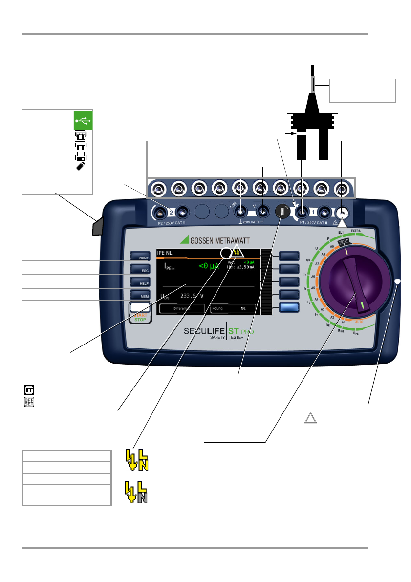
MEM: Database
ESC
: Return
HELP: Help images
START
: Start/Stopp
– Single meas.
– Test seq.
Finger contact
PRINT
: Print via USB
Softkeys
Fixed Function Keys
2 USB-Master
– For keyboard
– For scanner
– For printer
– For USB stick
1 USB-Slave
– For PC
!
Test socket for
connecting DUTs
Caution!
Depending on the measuring task, the test probe may
be charged with line voltage.
!
Rotary-
Selector Switch
Test sequences A1 ... A9
(test sequences per standard)
Rotary switch level: orange
Single measurements
Rotary switch level: green
LCD panel
Connection for
voltage supply
SECUTEST CLIP
(Z745H)
test probe
Fuse compartment
Voltage measurement
Sockets
2
nd
test probe
Special Symbol Displays:
– Measurement at IT line active
– OFFSET for RPE active
– for devices connected to the USB
master interface see above
AP A ... K
Applied parts sockets
Provided test sequences
Provided individual
measurements
See Page 7
Test sequence per
VDE 0701-0702
✔
IEC 62353
✔
IEC 60601 KA01
IEC 60974-4
✔
White/silver
identified and
fused high
current path
Kink protection grommet:
black: max. 16 A
green: max. 25 A
mains to test socket
SFC: normal condition
mains to test socket
SFC: N interrupted
SECULIFE ST PRO Operating and Connection Overview
Operating and Connection Overview
2 GMC-I Messtechnik GmbH
Page 3

SECULIFE ST PRO Contents / Scope of Delivery
Table of Contents Page
1 Safety Precautions .....................................4
2 Initial Start-Up ...........................................6
2.1 Mains Connection ........................................ 6
2.2 Detection of Mains Connection Errors ............ 6
Functions Overview of Instrument ................ 7
3
4 User Interface Symbols – Parameter and
Softkey Symbols ........................................8
5 Internal Database ......................................9
5.1 Creation of Test Structures ...........................9
Export – Transmission and Storage of Test
5.2
Structures and Measurement Data ................... 9
5.3
Import ............................................................. 9
6 Data Input ..................................................9
6.1 Entry via Touch Screen .................................9
7 Notes on Saving Single Measurements
and Test Sequences ................................10
8 Single Measurements ..............................11
8.1 RPE – Protective Conductor Resistance for
Protection Class I Devices ...........................12
8.2 RINS – Insulation Resistance Measurement
for Protection Class I Devices ......................13
8.3 RINS – Insulation Resistance Measurement
for Protection Class II Devices .....................14
8.4 IPE – Protective Conductor Current .............15
8.5 IT – Touch Current .....................................16
8.6 IE – Device Leakage Current .......................17
8.7 IA –
8.8 IP – Patient Leakage Current ......................19
8.9 IPA – Patient Auxiliary Current ....................20
8.10 U – Probe Voltage ......................................21
8.11 U – Measuring Voltage ...............................22
8.12 FT – Functions Test ...................................23
8.13 EL1 – Function Testing of Extension Cords ..24
8.14 EXTRA – Special functions ..........................25
8.15 2-Pole Measurements with P1 &
8.16 Measurement with Current Clamp Sensor at
8.17 Measurements with Test Adapter ............... 28
Leakage Current from the Appl. Part ...........18
P2 Test Probes .......................................... 27
Permanently Installed DUTs of Safety Class I
9 Test Sequences in AccordanSce with
Standards ................................................ 29
9.1 General Procedure .................................... 29
9.2 Evaluation Procedure ................................. 29
9.3 Sample Test Sequence .............................. 30
10 Parameters for Individual Measurements
and Test Sequences ................................ 34
11 Repair and Replacement Parts Service
Calibration Center and Rental Instrument
Service .................................................... 34
12 Product Support ...................................... 34
13 Declaration of Conformity ....................... 35
14 Database Software ................................. 36
Scope of Delivery
Standard Version (country-specific)
1 Test instrument SECULIFE ST PRO
1 Mains connection cable
1 Test probe, 2 m, not coiled
1 USB cable, USB A to USB B, length: 1.0 m
1 Plug-on alligator clip
1 Cable set KS17-ONE
1 Calibration certificate
1 Condensed operating instructions
– Complete operating instructions avail-
able for download from our website
1 Card with registration key for
IZYTRONIQ BUSINESS Starter software
(software available for web download)
Order Options
M7050- without with
Touch screen — E01
10 A RPE test current — G01
5 A RPE test current — G02
2
2nd test probe — H01
Voltage measuring input * — I01
Applied parts sockets — J01
Test sequence per IEC 60601 KA00 KA01
Z853R – SECUTEST DB+ — KB01
IZYTRONIQ compatible — KC01
27
Z853S – SECUTEST DB COMFORT
®
Bluetooth
* for voltage measurement, for connecting current clamp
sensors or AT3 adapters as well as for temperature
measurement via RTD
— KD01
M00 M01
GMC-I Messtechnik GmbH 3
Page 4

Note!
Attention!
!
Attention!
!
SECULIFE ST PRO Safety Precautions
1 Safety Precautions
SECUTEST BASE(10), SECUTEST PRO and
SECULIFE ST BASE(25) test instruments are
manufactured and tested in accordance with
the following safety regulations:
IEC/EN 61010-1 / VDE 0411-1, DIN VDE
0404, IEC/EN 61577 / VDE 0413-2,-4 / DIN
EN 61557-16 / VDE 0413-16
The safety of the user, the test instrument
and the device under test (electrical equipment or electrical medical device) is only
assured when the instrument is used for its
intended purpose.
Read these condensed operating instructions and
the full operating instructions carefully and completely before placing your test instrument into
service (available at our homepage www.gossenmetrawatt.com for download). Follow all instructions contained therein. Make sure that the operating instructions are available to all users of the
instrument.
Tests may only be performed by a qualified
electrician, or under the supervision and
direction of a qualified electrician. The user
must be instructed by a qualified electrician
concerning performance and evaluation of
the test.
Suitable personal safety equipment is
required.
If you use any active or passive implanted
medical devices, please consult your doctor
or the manufacturer of these devices.
Manufacturers and importers of electrical
medical devices must provide documentation for the performance of maintenance by trained personnel.
Observe the following safety precautions:
• The instrument may only be connected
to electrical systems (TN, TT or IT) with a
maximum of 240 V which complies with
applicable safety regulations (e.g. IEC
60346, VDE 0100) and is protected with
a fuse or circuit breaker with a maximum
rating of 16 A.
• Measurements within electrical systems
are prohibited.
• Be prepared for the occurrence of unexpected voltages at devices under test (for
example, capacitors can be dangerously
charged).
• Make certain that the measurement
cables are in flawless condition, e.g. no
damage to insulation, no cracks in
cables or plugs etc.
• When using a test probe with coil cord
(SK2W):
Grip the tip of the test probe firmly, for
example during insertion into a jack
socket. Tensioning at the coil cord may
otherwise cause the test probe to snap
back resulting in possible injury.
• Measurement of insulation resistance and
equivalent leakage current (leakage current
alternative measuring methods)
Testing is conducted with up to 500 V.
Current limiting is utilized (I < 3.5 mA),
but if terminals L or N at the test socket
are touched, electrical shock may occur
which could result in consequential accidents.
• Leakage current measurement during opera-
tion with line voltage: Please note that the
device under test is operated with line
voltage during measurement. Exposed
conductive parts may conduct dangerous touch voltage during testing. Do not
touch under any circumstances! (Mains
power is disconnected if leakage current
exceeds approx. 10 mA.)
The function test may only be performed after the DUT has successfully
passed the safety test!
• Probe check for probe connector P1: Please
perform a probe check after each test.
If there is a fuse defect in test probe
P1 after having started the test, all
subsequent measurements which
are performed with this measurement path might be erroneously
rated as good!
4 GMC-I Messtechnik GmbH
Page 5
!
SECULIFE ST PRO Safety Precautions
Fuse replacement
The fuses may only be replaced when the
instrument is voltage-free, i.e. the instrument
must be disconnected from mains supply
power and may not be connected to a measuring circuit. The fuse type must comply
with the specifications in the technical data
or the labeling on the instrument.
Opening the instrument / repairs
The instrument may only be opened by
authorized, trained personnel in order to
ensure flawless operation and to assure that
the guarantee is not rendered null and void.
Even original replacement parts may only be
installed by authorized, trained personnel.
If it can be ascertained that the instrument
has been opened by unauthorized personnel, no guarantee claims can be honored by
the manufacturer with regard to personal
safety, measuring accuracy, compliance
with applicable safety measures or any consequential damages.
Any warranty claims will be forfeited when
the warranty seal has been damaged or
removed.
Switching power consumers (max. 16 A*)
Be absolutely sure to adhere to the
sequence specified below when switching
the live device under test. This prevents
excessive wear of the mains relays at the
test instrument.
The test instrument may not be used:
• If external damage is apparent, for example
if parts which conduct dangerous touch
voltage are freely accessible, if the display
is broken or defective (in which case dangerous voltage or mains connection errors
might no longer be indicated)
• If the seal or sealing lacquer has been
removed as the result of repairs or manipulation carried out by a non-authorized/noncertified service provider.
• With damaged connection and/or measurement cables and patient ports, e.g.
interrupted insulation or kinked cable
• If the instrument no longer functions flawlessly
• After serious damage due to transport
In such cases, the instrument must be
removed from operation and secured
against unintentional use.
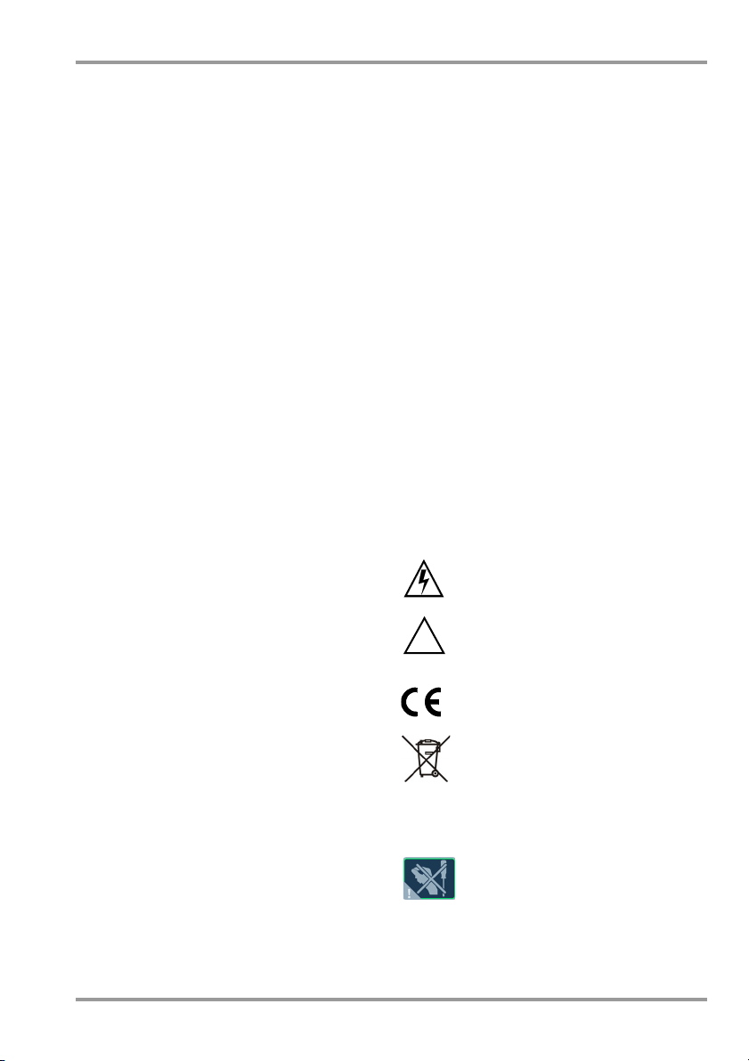
Meanings of Symbols on the Instrument
The symbols on the instrument have the following meanings:
Warning regarding dangerous
electrical voltage
Warning concerning a point of
danger (attention: observe documentation!)
Before measurement:
1) DUT: Turn the DUT off via its own switch.
2) Tes te r :
3) DUT: Turn the DUT on via its own switch.
After measurement:
4) DUT: Turn the DUT off via its own switch.
5) Tes te r :
* for currents > 16 A AC please use adapter
AT3-II S32 (Z745X)
GMC-I Messtechnik GmbH 5
Switch line voltage to the test
socket.
Deactivate line voltage to the test
socket.
QR CODE QR CODE is a registered
Indicates European Conformity
This device may not be disposed of
with the trash. Further information
regarding the WEEE mark can be
accessed on the Internet at
www.gossenmetrawatt.com by
entering the search term „WEEE“.
If the guarantee seal is damaged
or removed, all guarantee claims
are rendered null and void.
trademark of
DENSO WAVE INCORPORATED
Page 6
Attention!
!
Attention!
!
Note!
SECULIFE ST PRO Initial Start-Up
2 Initial Start-Up
2.1 Mains Connection
Nominal mains values: 100 to 240 V, 50 Hz to 400 Hz
➭ Connect the test instrument to the mains
cable via its inlet plug and insert the
mains plug into an electrical outlet. The
function selector switch can be set to
any position. If a mains outlet (earthing
contact outlet) is not available, or if only a
3-phase outlet is available, the adapter
socket can be used to connect the
phase conductor, the neutral conductor
and the protective conductor. The
adapter socket has three permanently
attached cables and is included with the
KS13 cable set (see wiring diagram in
the operating instructions).
If connection is not possible via an
earthing contact outlet: Shut down
mains power first. Then connect the
cables from the coupling socket to
the mains using pick-off clips in accordance with the diagram. Disconnection from mains power is only
possible with the mains plug.
Measurements in IT Systems (as from FW 1.5.0)
The setting IT system can be activated in
selector switch position SETUP (Setup 1/3)
under sub-menu All Measurement:
Parameter „Meas. at IT-mains“ = Yes: active
leakage current measurements (and/or all
measurements which include the PE at the
mains connection end) are blocked. Test
sequences which contain such kind of measurements are disabled as well.
2.2 Detection of Mains Connection Errors
The device automatically recognizes mains
connection errors if the conditions in the following table have been fulfilled. The user is
informed of the type of error, and all measuring
functions are disabled in the event of danger.
Typ e o f
Connection Error
Voltage at protective conductor PE
to finger contact
(START/STOP key)
Protective conduc-
tor PE & phase
conductor L
reversed and/or
neutral conductor
N interrupted
Line voltage
< 180 V / < 90 V
(depending on mains)
Tes t o n IT/TN
system
1
10 A/25 A
voltages of 115/230 V and line frequencies of 50/60 Hz.
2
if the test person is highly insulated, the following error
message may appear: „Interference voltage at PE of
mains connection“
Message Condition
Press START/
Display at the
instrument
Display at the
instrument
RPE measurements are only possible with line
STOP button
U 25 V
Button PE:
< 1 M
Voltage at PE
>100V
U
L-N
U
L-N
Connection
N PE
> 20 k
In the event of mains connection errors as described in either of the first
two cases in the table above, immediately disconnect the test instrument
from the mains and arrange to have
the error eliminated!
Voltage at the
tive conductor PE
electrical system’s
may result in distorted
measurement values during testing for
the absence of voltage, or during leakage voltage measurements.
< 180 V
<90V
Measure-
All measure-
2
under certain
under certain
circumstances
ments
ments
disabled
Impossible
(no supply
power)
Possible
circum-
stances
Possible
protec-
1
6 GMC-I Messtechnik GmbH
Page 7
Note!
SECULIFE ST PRO Scope of Features
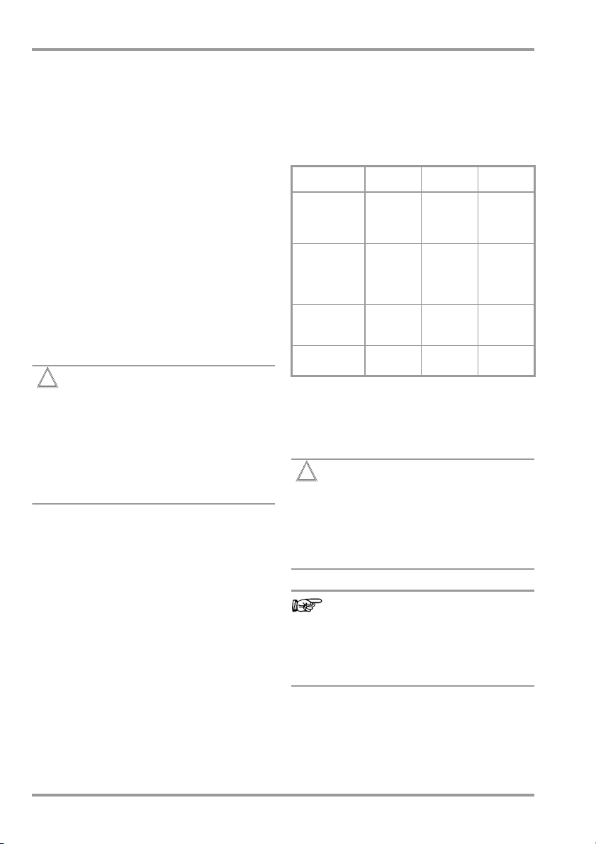
3 Functions Overview of Instrument
Switch
setting
Single measurements,
Measurements at voltage-free objects
R
Page 12
R
Page 13
Measurements at DUTs with line voltage
I
PE
Page 15
I
T
Page 16
I
E
Page 17
I
A
Page 18
I
P
Page 19
I
PA
Page 21
U
Page 21
Measuring functions,
test current/voltage
R
PE
Ip test current 200 mA
R
INS
U
I
PE
I
PE~
I
PE=
U
U
I
T
I
T~)
I
T=
U
U
I
E
I
E~
I
E=
U
U
I
A
U
U
I
P
I
P~
I
P=
U
I
PA
I
PA~
I
PA=
U
U probe voltage, TRMS
U
U
U RMS Voltage
U
U
protect. conductor resistance
PE
test current 10 A
test current 25 A
insulation resistance
INS
test voltage
INS
prot. conductor current, TRMS
AC component
DC component
test voltage
LPE
reference voltage (alternative)
Gen
touch voltage, TRMS
AC component
DC component
test voltage
LPE
reference voltage (alternative)
Gen
device leakage current, TRMS
AC component
DC component
test voltage
LPE
reference voltage (alternative)
Gen
leakage current from app. part
test voltage
LPE
voltage at applied part
Gen
patient leakage current, TRMS
AC component
DC component
test voltage
LPE
Patientenhilfsstrom effektiv
AC component
DC component
test voltage
LPE
AC voltage component
~
DC voltage component
=
AC voltage component
~
DC voltage component
=
rotary switch level: green
1
(Feature G01)
1)
(Feature G02)
2
2
2
Switch
setting
P (FT)
Measuring functions,
test current/voltage
Function test at the test socket
I current between L and N
U voltage between L and N
f frequency
P active power
S apparent power
Page 23
PF power factor
Probe measuring functions
EL1
Page 24
EXTRA
Page 25
Test sequences per standard
Page 29
Function test of extension cord with EL1/VL2E/
AT3-IIIE adapter: continuity, short-circuit,
reversed wires
Reserved for expansions in connection with
software updates
4
°C Temperature measurement 2 with Pt100/Pt1000
IZ Measurement of current at clamp with
current clamp sensor
3)
A
time to trip for 10/30 mA PRCD
t
rotary switch level: orange
Preconfigured (freely selectable) test sequences
Features * KA00 / ** KA01 (IEC 60601 3rd edition)
A1
A2
A3
A4
A5
A6
A7 *
A8 *
A9 *
A7 **
A8 **
A9 **
1
2
3
4
IEC 62353 passive TS BF APs A-K SK I
IEC 62353 passive TS BF APs A-K SK II
IEC 62353 passive TS BF APs A-K SK I+II
IEC 62353 active auto.
IEC 62353 active auto.
IEC 62353 active
VDE 0701-0702 passive
VDE 0701-0702 active
VDE 0701-0702 EDV
IEC 60601 active auto.
IEC 60601 active auto.
IEC 60601
IEC 60601
10 A/25 A-RPE measurements are only possible with line
voltages of 115 V/230 V and line frequencies of 50 Hz/60 Hz.
Voltage measuring inputs
Measurement of time to trip not possible in IT systems.
No checking for reversed polarity takes place when the
EL1 adapter is used.
active
active
det
. BF APs A-K SK I
det
. BF APs A-K SK II
auto. det. BF
APs
A-K SK I+II
auto. DUT det. SK I+II
auto. DUT det. SK I+II
active auto. DUT det. SK I+II
det
. BF APs A-K SK I
det
. BF APs A-K SK II
auto. det. BF
auto. det. CF
APs
A-E SK I+II
APs
F-K SK I+II
Changes in test sequences A1 ... A9
are preserved even after switching off
the test instrument.
GMC-I Messtechnik GmbH 7
Page 8
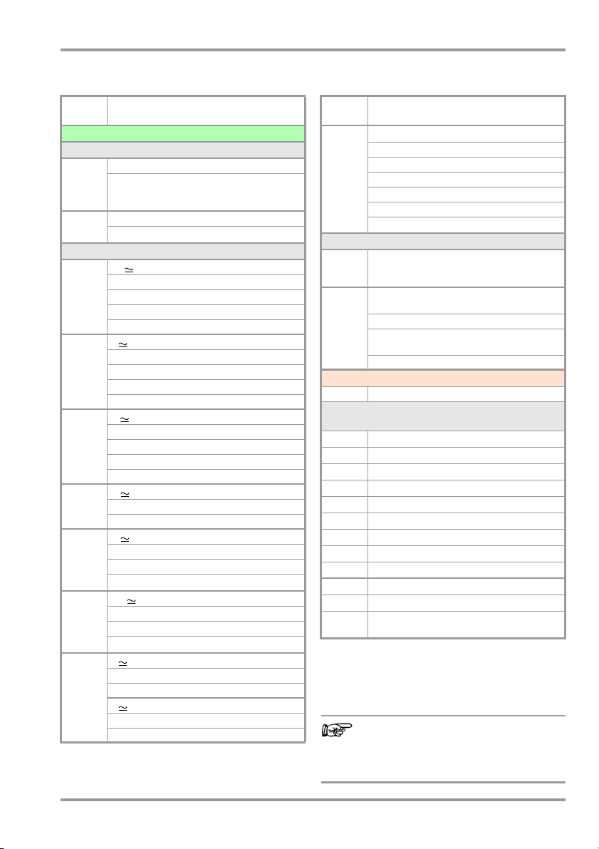
SECULIFE ST PRO Symbols
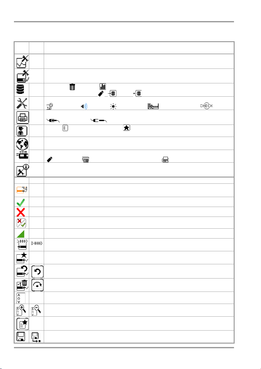
4 User Interface Symbols – Parameter and Softkey Symbols
Sym-
Setup
bols
Parameters and their significance
Page
Complete overviews of all symbols are included in the full operating instructions.
All measurements
1/3
have been standardized; Gnd fault sens.: continuous residual current monitoring (10/30 mA)
: Ref.voltage L-PE: voltage to which the measured values for leakage current
Automatic measurements: set parameters for test sequences: start and end view,
inclusive operation uncertainty (yes/no), auto measurement point (yes/no)
Database: deletion, statistics,
1/3
with inserted USB stick : save, restore database
System: set general device parameters;
1/3
2/3
2/3
2/3
2/3
3/3
date/time, volume, brightness,
Printer: printer selection for USB master interface
connected, disconnected
Te st er : select tester from list, add new tester
Culture: select language for operating instructions, keyboard and measuring
sequences by acknowledging the respective national flag; Reboot necessary!
Optionally connected external devices
USB stick, keyboard / barcode scanner, printer
System information: query software and hardware version, serial number, build
number, calibration data and storage occupancy
default settings, self-test
— Functions and their significance
Set classification parameters for the respective test sequence
(test sequences: switch settings A1 ... A9)
Accept parameters, acknowledge message
Abort single measurement or test sequence
Evaluate measurement of visual inspection with OK or not OK (toggle key)
Continue test, next test step in the test sequence
Symbol left: Direct selection key measurement type (connection type...) or measuring method (direct ...) / Symbol right: Selection between two states (no submenu)
Start evaluation – record measured value. Each time this softkey is pressed, an
additional measured value is saved and the number is increased by one.
Symbol left: Repeat measured value recording
Symbol right: Repeat test step in the test sequence
Symbol left: Delete measured value
Symbol right: Skip individual tests in the test sequence
Display measured values from performed measurements and test sequences
Magnifying glass symbol: show (+) or hide (–) details regarding database objects
or selected measurements
Enter a new ID for a test object either before or after a test, and in case the ID
has not yet been entered to the structure
Save measurement data / save measurement data as (with display of directory
path / ID or new entry of an ID other than the preselected one)
8 GMC-I Messtechnik GmbH
Page 9

Note!
Delete characters
Accept entry *
Display Field
Key Field
from right *
Switching between
uppercase and lowercase
* also possible via the associated softkey
SECULIFE ST PRO Database – Keyboard
5 Internal Database
5.1 Creation of Test Structures
A complete test structure with data regarding customers and devices under test be
created in the test instrument. This structure
makes it possible to store the results of single measurements or test sequences of test
objects belonging to various customers.
Manual single measurements can be
grouped together into a so-called „manual
sequence“.
base creation is included in the full operating
instructions for your test instrument.
5.2 Export – Transmission and Storage of
Structures set up in, and measurement data
saved to the test instrument can be imported
to the IZYTRONIQ report generating software
via a plugged-in USB stick (PRO and/or Feature KB01 only) or via the USB slave port.
Data can then be saved to the PC and
reports can be generated.
Furthermore, you can save the database to
a plugged-in USB stick for subsequent
restoring to the device memory.
5.3 Import
The test structures created at the PC with
the help of the report generating software
can be loaded into the test instrument via an
USB stick or via the USB slave port.
A complete description of data-
Test Structures and Measurement Data
Data transfer to IZYTRONIQ should not
be started during single measurements or test sequences.
6 Data Input
6.1 Entry via Touch Screen
After selecting ID or any other object parameter, a keyboard is displayed which allows
for the entry of alphanumeric characters via
touch screen. Alternatively, entries can also
be made with the help of a USB keyboard or
barcode scanner which is connected to the
instrument.
Procedure
(example: entering a DUT designation)
1 Switch the keyboard between upper-
case and lowercase via the field.
2 Switch the keyboard from numeric to
special character or alphabetic character
entry mode via the „123“, „sym“ or „abc“
field.
3 After pressing on the respective charac-
ter, it appears in the display field.
4 Repeat steps 1 through 3 until the com-
plete designation is shown in the display
field.
5 After pressing the green check-
mark, the selected character string
is saved.
The touch screen allows for the convenient
entry of data and comments, parameters
and direct parameter selection.
GMC-I Messtechnik GmbH 9
Page 10
SECULIFE ST PRO Saving
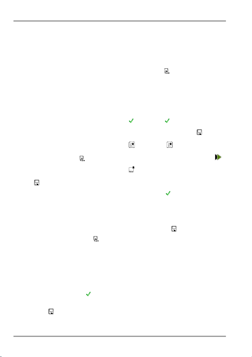
7 Notes on Saving Single Measurements and Test Sequences
At the end of each test, test results can be
saved under an ID number which is unequivocally assigned to the respective test object.
Depending on the initial situation, i.e.
whether or not a test structure or database
is already available or an ID has already been
entered, the following different procedures
are used for saving:
Variant 1 – pre-selection of an existing ID
You’ve already set up a test structure in the
test instrument
IZYTRONIQ
Open the database view before starting the
measurement by pressing the MEM key.
Then select the test object or its ID within the
test structure by pressing the respective
scroll key. Exit the database view (MEM navigation) by pressing ESC and start the measurement. Press the Save as key at the
end of the measurement. The display is
switched to the SAVE view. The ID appears
with a green or orange background. Press
the Save key in order to complete the procedure.
Variant 2 – entry of an existing ID at the end of the
test
You’ve already set up a test structure in the
test instrument
IZYTRONIQ (
measurement without first opening the database. No test object was previously selected
in the database. Press the Save as key at
the end of the measurement. The following
message appears: „No DUT selected!“
Press the ID key. The softkey keyboard
appears.
If you enter an ID here which is already in the
database, the database view appears automatically (MEM navigation) and the test
object’s ID is displayed inversely. Acknowledge the entry by pressing the key. The
display is switched to the SAVE view. The ID
appears with a green or orange background.
Press the Save key once again in order to
complete the procedure.
or loaded one from the
.
or loaded one from the
SECUTEST PRO
only)
. You perform the
Variant 3 – entry of a new ID at the end of the test
You haven’t yet set up a test structure in the
test instrument, or the ID is not included in
the existing structure.
Press the Save as key at the end of the
measurement. The following message
appears: „No DUT selected!“ Press the ID
key in order to enter the test object’s ID. The
softkey keyboard appears.
If you enter an ID here which is not yet
included in the database, a prompt appears
asking you if you want to enter a new object.
– : If you press , the display is switched
to the SAYVE view. The ID appears with a
green background. Press the key once
again in order to complete the procedure.
– : If you press , the database view
appears (MEM navigation). Go to the next
page (Process objects 2/3) by pressing ,
and then enter a new test object. Press
to this end. All possible object types
are displayed. Press „DUT“. The newly
entered ID appears in red to the right of
the ID parameter. Acknowledge the entry
by pressing the key. The display is
switched to the database view (MEM navigation). The newly entered test object is
displayed inversely in the structure. Press
ESC in order to return to the SAVE view. The
ID appears with a green or orange background. Press the key once again in
order to complete the procedure.
– ESC: If you don’t want to save any mea-
sured values, press ESC twice in order to
go to the measuring view. If you press ESC
again, a prompt appears asking whether
or not you want to delete the measuring
points in order to continue with the measurement without saving.
10 GMC-I Messtechnik GmbH
Page 11
MEM
ESC
3
3
3
Select DUT
Start stop initiate saving
1 2 3 4
Check end saving
SECULIFE ST PRO Single Measurements
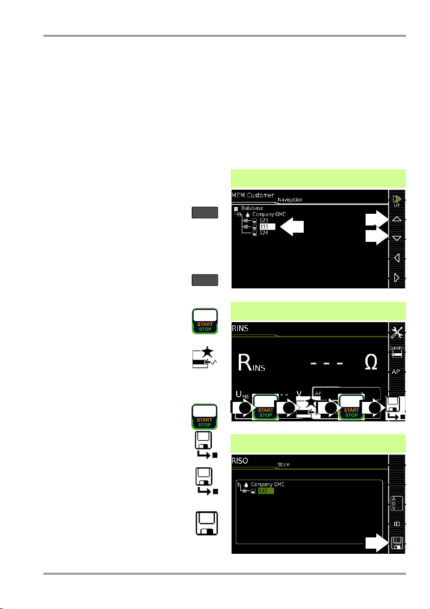
8 Single Measurements
Any measuring duration is possible. The
respective measurement is ended by pressing START/STOP. No limit values have been
entered for single measurements. As a
result, no evaluation of the measurement
results takes place.
Procedure for measuring with save function and
pre-selection of the (ME) device
If you’d like to save your single measurements to selected (ME) devices in a database (see section 5), the following procedure
is advisable.
1 Activate the database view (MEM
navigation) by pressing the MEM
key.
2 Select the (ME) device or its ID num-
ber for the following measurements
with the scroll keys.
3 Return to the measuring view by
pressing the ESC key or the START/
STOP key.
4 Start the test with the START/STOP
key before switching the DUT on.
The measured value recording
symbol shown at the right
appears. Each time this key is
pressed, the currently displayed
value is saved to the clipboard
and the number shown in the symbol is
increased by one.
5 Switch off the DUT before finish-
ing the test with the START/STOP
key. The Save as symbol appears
(floppy disk icon with the number
of measured values saved to the
clipboard).
6 If you press the save symbol now,
the display is switched to the SAVE
view, where the pre-selected (ME)
device is highlighted.
7 After pressing the Save symbol
once again, acknowledgement of
successful storage appears. At the
same time, the display returns to the
measuring view.
Procedure for measuring with save function and
subsequent entry of the (ME) device
As an alternative to the procedure described
above, you can start with step 4 and, after
measurement has been completed, assign
the results to a (ME) device or its ID number
which is included in the database: manually
by selecting ID and entering the ID via the
alphanumeric keyboard, or by scanning a
barcode.
GMC-I Messtechnik GmbH 11
Page 12

Select measuring function
1
R
PE
Select parameters
2
Set parameters
3
Connect DUT
4
PE(TS) – P1
P1
PE(mains) – P1
PE(mains)
P1
Start test
5
Acknowledge line voltage warning
6
!
With active: PE(TS)-P1 only
Save measured values to clipboard
6
Stop test
7
Save measurements under ID no.
8
SECULIFE ST PRO Single Measurements
8.1 RPE – Protective Conductor Resistance for Protection Class I Devices
1
The selected offset value is permanently stored to memory and
adapted for measurements in selector switch position
2
Connection also via EL1, VL2E, AT3 adapter, AT16DI/AT32DI
➭ Connect the DUT to the test socket.
➭ Contact all conductive parts which are
connected to the protective conductor
with test probe P1.
Special case: permanently installed DUT
Meas. Parameter Meaning
Mode (Measurement type)
admissible test current IP
PE(TS) – P1
@ IP =
200 mA/10 A/25 A
active: PE(TS)-P1
@ IP = 200 mA
PE(mains) – P1
Perm. conn. devices
@ IP = 200 mA
PE(Mains) – P1 clip @ IP = 10 A, see section 8.16
P1 – P2
@ IP =
200 mA/25 A
Testing between the 2 protective
conductor terminals: at test sock-
2
et
and test probe P1
same as PE(TS) – P1
mains voltage to socket and with
continuously increasing DC current
(PRCDs)
Testing between ground terminal
at mains and test probe P1
Only test devices with feature H01:
2-pole measurement between test
probe 1 and 2, see section 8.15
but with
➭ Contact all conductive housing parts
with test probe P1.
IP(set) Ip
200 mA
10 A Test current: 10 A
25 A Test current: 10 A
Test cur.: 200 mA AC (+/–/± DC)
(Feature G01)
(Feature G02)
f – only at 200 mA ~ (AC)
50 to 200 Hz
Offset
> 0 to < 5
1
Test sequence (adjustable in increments)
Zero balancing for selected ref. point.
AUTO
.
12 GMC-I Messtechnik GmbH
Page 13

Select measuring function
1
RINS
Select parameters
2
Set parameters
3
Connect DUT, Connect APs
4
LN(TS) – AP
P2 – AP
P1
Start test
5
Save measured values to clipboard
6
Stop test
7
Save measurements under ID no.
8
SECULIFE ST PRO Single Measurements
8.2 RINS – Insulation Resistance Measurement for Protection Class I Devices
Meas. Parameter Meaning
AP on / off
Selection: A / B / C / D / E / F / G / H / I / K
UINS(set)
> 50 to < 500 V Variable test voltage can be en-
1
Connection also via EL1, VL2E, AT3-II I E, AT3-I IS, AT3-II S32,
AT16DI/AT32DI or CEE adapter
tered with the numeric keypad
U+/U– = increase/decrease UINS(set)
Meas. Parameter Meaning
Mode (Measurement type)
LN(TS) – PE(TS)
LN(TS) – P1 See section 8.3
P1 – P2
PE(Mains) – P1
Permanently
connected devices
PE(TS) – P1
LN(TS) – P1//PE(TS)
LN(TS) – AP Testing is performed between the
PE(Mains) – AP
PE(TS) – AP
P1//PE(TS) – AP
P2 – AP
PC I: Testing between short-circuited LN mains terminals at test
socket and the DUT’s PE terminal
Only test devices with feature H01:
2-pole measurement between test
probe 1 and 2 instead of test socket
connection
Cable test: Testing between ground
terminal at mains and test probe P1
Testing between PE terminal at test
socket and test probe P1
Testing between short-circuited LN
mains terminals at test socket and test
probe P1, including PE at test socket
indicated measuring point (see
above) and the sockets of the selected applied parts
Special case P2 – AP
1
➭
Connect the DUT with the test socket (TS)
and the applied parts with the applied
parts sockets.
➭
P2-AP:
ductive, exposed parts which are not connected with the protective conductor.
➭ Switch DUT on
➭ Switch DUT off
Contact with test socket P2 the con-
GMC-I Messtechnik GmbH 13
Page 14

Select measuring function
1
RINS
Select parameters
2
Set parameters
3
Connect DUT
4
P1//PE(TS) – AP
P1
Start test
5
Save measured values to clipboard
6
Stop test
7
Save measurements under ID no.
8
SECULIFE ST PRO Single Measurements
8.3 RINS – Insulation Resistance Measurement for Protection Class II Devices
➭ Connect the DUT with the test socket
and the applied parts with the applied
parts sockets.
➭ Contact all conductive, exposed parts
with test probe P1.
➭ Switch DUT on
Measuring
Meaning
➭ Switch DUT off
Parameters
Mode (Measurement type)
LN(PD) – P1 ... between short-circuited LN TS* & P1
LN(PD)
– AP ... between short-circuited LN TS & AP
P2
– AP ... between test probe P2 & AP
AP on / off
Selection: A / B / C / D / E / F / G / H / I / K
UINS(set)
> 50 to < 500 V Variable test voltage can be entered with
* Connection via test socket, via adapter VL2E, AT3-
IIIE,
AT3-II S, AT3-II S32 or AT16DI/AT32DI
the numeric keypad
)
Legende
AP = Applied part; TS = test socket
P1//PE(TS) = test probe P1 parallel with PE test
socket
14 GMC-I Messtechnik GmbH
Page 15

Select Measuring Function
1
IPE
Select parameters
2
Set parameters
3
Connect DUT
4
Direct / Diff / Alt
Start test
5
Acknowledge line voltage warning
6
!
Direct & differential & AT3 Adapter:
Save measured values to clipboard
7
Stop test
8
Save measurements under ID no.
9
SECULIFE ST PRO Single Measurements
8.4 IPE – Protective Conductor Current
Prior to all leakage current measurements, please
make sure that the measurement parameters „Ref.
voltage L-PE“ and „Testingfreq. Alt“ have been cor-
rectly set in the SETUP, see section 10.
➭ Connect the DUT with the test socket
and the applied parts with the applied
parts sockets.
Meas. Parameter Meaning
Mode (Measurement type)
Direct
Differential Differential current measurement
Alternative Equivalent leakage current mea-
AT3-adapter
Clip
Test conditions – for direct mode only
None / AP > PE
Clip factor – for clip mode only
1mV : 1mA / 10mV : 1mA / 100mV : 1mA / 1V : 1mA
Single Fault Cond. – for direct mode only SFC
Normal condition / N interrupted
Polarity – for direct & differential mode only
L/N or N/L Selection of polarity for line volt-
1
Connection also via VL2E, AT3 adapter, AT16DI/AT32DI
GMC-I Messtechnik GmbH 15
Direct measuring method (via test
socket, AT16DI/AT32DI)
(via test socket)
suring method (via test socket
Measurement with adapter AT3-
IIIE,
AT3-II S or AT3-II S32
See section 8.17
See section 8.16
age at test socket
➭ Switch DUT on
1
)
➭ Switch DUT off
Page 16

Select measuring function
1
IT
Select parameters
2
Set parameters
3
Connect DUT
4
Direct P1/ Diff P1/ Alt P1
P1
Start test
5
Acknowledge line voltage warning
6
!
Direct & differential:
Save measured values to clipboard
7
Stop test
8
Save measurements under ID no.
9
SECULIFE ST PRO Single Measurements
8.5 IT – Touch Current
Prior to all leakage current measurements, please
make sure that the measurement parameters „Ref.
voltage L-PE“ and „Testingfreq. Alt“ have been correctly set in the SETUP, see section 10.
➭ Connect the DUT with the test socket
and the applied parts with the applied
parts sockets.
➭ Contact additional, accessible, conduc-
tive parts which are not connected to the
protective conductor with test probe P1.
Meas. Parameter Meaning
Mode (Measurement type)
Direct P1 Direct measuring method
Differential P1 Differential current measurement
Alternative P1
Permanent connection P1Permanently connected DUT
Alternative P1–P2
(via test socket
(via test socket)
Equivalent leakage current measuring
method (via test socket
Only test devices with feature H01:
Equivalent leakage current measurement method:
2-pole measurement between test
probe 1 and 2, see section 8.15
1
)
1
or VL2E)
➭ Switch DUT on
➭ Switch DUT off
Test cond. – for direct and perman. mode only
None / AP > PE (all APs)
Single Fault Cond. – for direct mode only SFC
Normal condition / N interrupted / PE interrupted
Polarity – for direct and differential mode
only
L/N or N/L Selection of polarity for line volt-
1
16 GMC-I Messtechnik GmbH
Connection also via
age at test socket
AT3-II I E, AT3-II S, AT3-II S32, AT16DI/AT32DI
Page 17

Select measuring function
1
IE
Select parameters
2
Set parameters
3
Connect DUT
4
Direct / Diff / Alt
P1
Start test
5
Acknowledge line voltage warning
6
!
Direct & differential & AT3 Adapter:
Save measured values to clipboard
7
Stop test
8
Save measurements under ID no.
9
SECULIFE ST PRO Single Measurements
8.6 IE – Device Leakage Current
➭ Connect the DUT with the test socket
and the applied parts with the applied
parts sockets.
➭ Contact accessible, conductive parts
which are not connected to the protective conductor with test probe P1.
Meas. Parameter Meaning
Mode (Measurement type)
Direct Direct measuring method (via test
Differential Differential current measurement
Alternative Equivalent leakage current mea-
AT3-adapter
Clip
Polarity – for direct, differential mode
and AT3-adapter only
L/N or N/L Selection of polarity for line
Factor V:A – for clip mode only
1mV : 1mA / 10mV : 1mA / 100mV : 1mA / 1V : 1mA
1
Connection also via AT16DI/AT32DI (only useful for differential current method)
Prior to all leakage current measurements, please
make sure that the measurement parameters „Ref.
voltage L-PE“ and „Testingfreq. Alt“ have been correctly set in the SETUP, see section 10.
GMC-I Messtechnik GmbH 17
socket1), optional probe contact
(via test socket)
suring method with probe contact
(via test socket, AT16DI/AT32DI)
Measurement with adapter AT3IIIE,
AT3-II S or AT3-II S32
See section 8.17
See section 8.16
voltage at test socket
➭ Switch DUT on
➭ Switch DUT off
Page 18

Select measuring function
1
IA
Select parameters
2
Set parameters
3
Connect DUT
4
Direct AP
AP – P2
P2
Start test
5
Acknowledge line voltage warning
6
!
Direct:
Save measured values to clipboard
7
Stop test
8
Save measurements under ID no.
9
SECULIFE ST PRO Single Measurements
8.7 IA –
Leakage Current from the Appl. Part
Meas. Parameter Meaning
Mode (Measurement type)
Direct P1 Direct measuring method (via test
Direct AP as above, here via AP socket
Alternative P1 Equivalent leakage current mea-
Alternative AP as above, here via AP socket
Permanent connection P1
Perman. conn. AP as above, here via AP socket
1)
AP – P2
socket) with test probe P1
suring method (via test socket)
with test probe P1
Permanently connected DUT
Test probe P2 at cond. parts without PE
AP on / off
Selection: A / B / C / D / E / F / G / H / I / K
Phase Angle – for Direct... and Perm. c. only
0 ° or 180 ° Selectable phase angle of the in-
ternal generator in relation to
mains phase angle
Polarity – for direct mode only
Prior to all leakage current measurements, please
make sure that the measurement parameters „Ref.
voltage L-PE“ and „Testingfreq. Alt“ have been correctly set in the SETUP, see section 10.
➭ Connect the DUT with the the test
socket and the applied parts with the applied parts sockets.
Special case AP – P2
➭
Contact with test probe P2 the conductive, exposed parts which are not connected with the protective conductor.
➭ Switch DUT on
➭ Switch DUT off
L/N or N/L Selection of polarity for line volt-
1)
for ME devices with proprietary power supply
18 GMC-I Messtechnik GmbH
age at test socket
Page 19

Select measuring function
1
IP
Select parameters
2
Set parameters
3
Connect DUT
4
P1
Direct AP
Perman. connection AP
P1
Start test
5
Acknowledge line voltage warning
6
!
Direct:
Save measured values to clipboard
7
Stop test
8
Save measurements under ID no.
9
SECULIFE ST PRO Single Measurements
8.8 IP – Patient Leakage Current
Meas. Parameter Meaning
Measurement mode
Prior to all leakage current measurements, please
make sure that the measurement parameters „Ref.
voltage L-PE“ and „Testingfreq. Alt.“ have been cor-
rectly set in the SETUP, see section 10.
➭
Connect the DUT with the test socket and
the applied parts with the AP sockets.
➭ Contact with test
probe
P1 the conductive, exposed parts with are not connected with the protective conductor.
Special case permanent connection
Direct P1 Direct measuring method (via test
Direct AP Measurement via selected applied
Permanent connection P1
Perman. connect. AP Measurement via selected applied
Test conditions – for AP mode only
AP to PE / housing to PE / AP & housing to PE / none
AP on / off
Selection: A / B / C / D / E / F / G / H / I / K
Single Fault Condition – depending on mode
Normal condition / N interrupted / PE interrupted /
Mains at applied parts
Polarity – for direct mode only
L/N or N/L Selection of polarity for line
GMC-I Messtechnik GmbH 19
socket) with test probe P1
parts sockets
Permanently connected DUT
parts sockets
➭ Switch DUT on
➭ Switch DUT off
voltage at test socket
Page 20

Select measuring function
1
IPA
Select parameters
2
Set parameters
3
Connect DUT
4
Direct AP
Perman. connection AP
Start test
5
Acknowledge line voltage warning
6
!
Direct:
Save measured values to clipboard
7
Stop test
8
Save measurements under ID no.
9
SECULIFE ST PRO Single Measurements
8.9 IPA – Patient Auxiliary Current
➭
Connect the DUT with the test socket and
the applied parts with the AP sockets.
Special case permanent connection
Meas. Parameter Meaning
Mode (Measurement type)
Direct AP Direct measurement from the
Perman. connect. AP Direct measurement from the
selected AP socket to all other
sockets
selected AP socket to all other
sockets (no individual errors or
polarity selectable)
AP on / off
Selection: A / B / C / D / E / F / G / H / I / K
towards remaining applied parts each
➭ Connect the applied parts with the AP
sockets.
➭ Switch DUT on
Single Fault Condition – direct mode only
Normal condition / N interrupted / PE interrupted
Polarity – direct mode only
L/N or N/L Selection of polarity for line volt-
age at test socket
➭ Switch DUT off
Prior to all leakage current measurements, please
make sure that the measurement parameters „Ref.
voltage L-PE“ and „Testing freq. Alt.“ have been correctly set in the SETUP, see section 10.
20 GMC-I Messtechnik GmbH
Page 21

Select measuring function
1
U
Select parameters
2
Set parameters
3
Connect DUT
4
PE – P1 (with mains)
Probe Voltage
P1
PE – P1
Probe Voltage
P1
Start test
5
Acknowledge line voltage warning
6
!
Only for measurement
type:
(with mains)
Save measured values to clipboard
7
Stop test
8
Save measurements under ID no.
9
SECULIFE ST PRO Single Measurements
8.10 U – Probe Voltage
➭ Connect the DUT to the test socket.
➭ Contact the ungrounded output for pro-
tective extra-low voltage with test probe
P1.
➭ Select line voltage polarity.
Special case: permanently installed DUT
➭ Contact all voltage conducting parts with
test probe P1.
Meas. Parameter Meaning
Mode (Measurement type)
PE – P1 Measurement of voltages with
PE – P1 (with Mains) Measurement of voltages with
L/N or N/L Selection of polarity for line volt-
GMC-I Messtechnik GmbH 21
reference to PE, test socket remains voltage-free, e.g. for permanently connected DUTs
reference to PE, line voltage is applied to the test socket
age at test socket
(with mains)“ only)
(with „PE – P1
➭ Switch DUT on
➭ Switch DUT off
Page 22

Select measuring function
1
U
Select parameters
2
Set parameters
3
Connect DUT
4
V – COM (with mains)
Measuring Voltage
VCOM
!
V – COM (RMS/AC/DC)
Meas. Volt.
VCOM
Start test
5
Acknowledge line voltage warning
6
!
Only for measurement
type:
(with mains)
Save measured values to clipboard
7
Stop test
8
Save measurements under ID no.
9
SECULIFE ST PRO Single Measurements
8.11 U – Measuring Voltage
Attention!
Only use the enclosed contact pro-
tected KS17-ONE measurement
cables for the measurement of dangerous
voltages please.
Special case: permanently installed DUT
➭ For testing mains power packs and charging
units: Connect the DUT mains terminal
with the test socket.
➭ Connect the DUT output, e.g. for mea-
suring safety extra low voltage (SELV),
with sockets V and COM.
Meas. Parameter Meaning
Mode (Measurement type)
V – COM (RMS) Effective value
V – COM (AC) AC value for perm. conn. DUTS
V – COM (DC) DC value for perm. conn. DUTS
V – COM Effective value + AC + DC for
V – COM (with mains) Effective value + AC + DC;
for permanently connected DUTs
perm. conn. DUTS
for line voltage at test socket
➭ Switch DUT on
➭ Switch DUT off
22 GMC-I Messtechnik GmbH
Page 23

Note!
Select measuring function
1
P
Select parameters
2
Set parameters
3
Connect DUT
4
Starting test
5
Acknowledge line voltage warning
6
!
Save measured values to clipboard
7
Stop test
8
Save measurements under ID no.
9
SECULIFE ST PRO Single Measurements
8.12 FT – Functions Test
➭ Connect the DUT to the test socket.
Meas. Parameter Meaning
Polarity
LN Phase L – neutral conductor N
NL Neutral conductor N – phase L
The following connection types are possible:
• Test socket
• CEE adapter (only for connection via
single-phase CEE or „caravan socket“)
• AT3 adapter (AT3-I I IE, AT3-IIS, AT3-IIS32)
• AT16DI/AT32DI
It is possible to use the adapters
listed above for function testing (initial
start-up of DUT). Apparent/active
power, power factor and current consumption can only be measured,
however, if the DUT is directly connected with the test socket or via the
CEE adapter (single-phase CEE
socket only).
GMC-I Messtechnik GmbH 23
➭ Switch DUT on
➭ Switch DUT off
Page 24

Note!
Select measuring function
1
EL1
Select parameters
2
Set parameters
3
Connect DUT
4
Test Socket – P1
EL1-Adapter
P1
VL2E-adapter
Start test
5
Save measured values to clipboard
6
Stop test
7
Save measurements under ID no.
9
SECULIFE ST PRO Single Measurements
8.13 EL1 – Function Testing of Extension Cords
Connection of EL1 Adapter
Meas. Parameter Testing for
Measurement type
Continuity
L(1/2/3), N
Short-circuit
between
L(1/2/3), N
Reversed
polarity /
Clockwise
EL1 adapter
VL2E adapter
AT3-IIIE adapter
XX —
XX X
XX X
This function allows for the evaluation of the
function of the active conductors L (1, 2, 3)
and N of an extension cable. The PE conductor
is not being tested in this process!
For the testing of R
tive single measurements.
and R
PE
see respec-
INS
➭ Connect the EL1 adapter to the P1
probe sockets at the test instrument.
➭ Connect the plug at the end of the ex-
tension cord to the test socket.
➭ Connect the coupling socket at the end
phase
of the extension cord to the plug at the
sequence
EL1 adapter.
Connection of Test Adapters VL2E and AT3-IIIE
➭ Connection examples are shown in sec-
tion 8.17.
Continuity test for L and N
See section 9, „Test Sequences in
Accordance with Standards“ (switch
setting A8) with regard to testing extension cords per DIN VDE 0701-0702, for
24 GMC-I Messtechnik GmbH
which RPE and R
are measured.
INS
Page 25

Select measuring function
1
EXTRA
Temp., Current (clip) or PRCD break time
2
3Connect DUT
4
V – COM PT100(0)
Start test
4
Save measured values to clipboard
5
Stop test
6
SECULIFE ST PRO Single Measurements
8.14 EXTRA – Special functions
Temp. – Temperature measurement
Additional measurement
functions are assigned to
rotary switch position
EXTRA.
➭ Select the desired measuring function.
GMC-I Messtechnik GmbH 25
Temperature measurement works both with
a Pt100 and a Pt1000 temperature sensor
and automatically recognizes the utilized
sensor type.
Page 26

3Connect DUT
4
VCOM
V – COM (AC) (w. Mains)
Set parameters
5
Start test
6
Save measured values to clipboard
7
Stop test
8
3
Connect DUT
4
P1
Start test (test current 30 mA)
5
Acknowledge line voltage warning
6
!
Execute test
7
Testing is stopped automatically.
8
Save measurements under ID no.
9
SECULIFE ST PRO Single Measurements
IZ – Current clamp measurement
tA – PRCD Time to Trip
(portable residual current device)
➭ Connect the PRCD to the test socket.
Meas. Parameter Meaning
Measurement type
V – COM (AC) A AC for permanently connected
V – COM (AC) (with
Mains)
Polarity – Mode with mains at TS only
L/N or N/L Selection of polarity for line
➭
Adjust the clamp factor (cl. factor):
– at the current clamp sensor
DUTs
A AC; for line voltage at test
socket
voltage at test socket
➭ Activate the PRCD.
➭ Contact neutral conductor L at the
PRCD with test probe P1 (if required, ascertain by trial and error).
The PRCD is tripped.
– at the test instument
Ascertained time to trip is displayed.
26 GMC-I Messtechnik GmbH
Page 27

P1P2
Switch position: R
PE
Measurement type: P1-P2
P1P2
Switch position: R
INS
Switch position: IT
Measurement type: P1-P2
V
COM
P1
Switch position: R
PE
Measurement type: Clamp
V
COM
Switch position: I
PE
Measurement type: Clamp
Switch position: IE
Measurement type: Clamp
COM-V
SECULIFE ST PRO Single Measurements
8.15 2-Pole Measurements with P1 & P2 Test Probes
In case your DUT is not equipped with a
country-specific mains plug that fits into the
tester test socket or if it is a permanently
installed DUT, the 2
nation with the 1
pole measurement (dual-lead measurement) of RPE, RINS and equivalent leakage
current.
Measurements with test probe 1 against test
probe 2 (P1 – P2) are electrically isolated
from the mains. There is no voltage present
at the test probe.
Connection Example of RPE Measurement
Measuring of protective conductor resistance RPE at permanently installed safety
class I devices
nd
test probe, in combi-
st
test probe, allows for 2-
8.16 Measurement with Current Clamp Sensor at Permanently Installed DUTs of Safety Class I
SECUTEST PRO and
SECUTEST PRO
Parameter
Tra n sf. Ra t i o
1 mV :1 mA
Connection Example for RPE Measurement (WZ12C only)
Measurement of test current by enclosing
PE in the electric circuit. This type of measurement can only be selected if the test
current has been set at 10 A AC.
Connection Example for IPE Measurement
(Direct measuring method)
SECULIFE ST BASE(25)
Clamp SECUTEST PRO
Tra ns-
former Ratio
1 mV : 1 mA
Measuring
WZ12C
1 mA ...
Range
15 A
only
Display Range
with Clamp
0 mA ... 300 A
Connection Example of RINS or IT
Measurements
Measuring of insulation resistance RINS or
touch current IT for safety class I devices
Measurement of protective conductor current by enclosing PE in the feeder.
Connection Example of IE Measurement
(Differential current measurement)
GMC-I Messtechnik GmbH 27
Measurement of device leakage current by
L and N
in the
enclosing conductors
feeder
.
Page 28

Attention!
!
EL1 adapter
P1
P1
COM-V
P1
SECULIFE ST PRO Single Measurements
8.17 Measurements with Test Adapter
Test with Adapter
EL1 VL2E AT3-
DUT terminals
Inlet plug 1P+N+PE 16 A
Schuko 1P+N+PE 16 A
CEE 1P+N+PE 16 A
CEE 3P+N+PE 16 A
CEE 3P+N+PE 32 A
5 x 4 mm sockets
— ✔✔ — —
— ✔ — — —
— ✔✔ — ✔
— ✔✔✔ / — ✔
— ✔✔— / ✔✔
——— — ✔
Test instrument terminals
Schuko 1P+N+PE 16 A
Socket for test probe
Plug for V–COM
—— ✔✔ —
— ✔✔ ——
1
—— ✔ ——
Active Testing
Protective conductor current IPE
– Direct method
– Differential current
—— ✔✔ —
——✔1✔ —
Device leakage current IE
– Direct method
– Differential current
Touch current IT
—— ✔✔ —
——✔1✔ —
—— ✔✔ —
Passive Testing
Protective conductor
resistance RPE
Insulation resistance
RINS
Protective conductor
current IPE (equiv. leakage current method)
Extension cables:
apart from RPE & RINS are conducted in switch position
single phase (3-pole)
3-phase (5-pole)
wire short circuit
wire interruption
wire reversal
1
Differential current method with
2
for IPE and IE: AT3-IIS or, alternatively, AT3-I I S32
✔✔ ✔ ✔ ✔
✔✔ ✔ ✔ ✔
— ✔✔ ✔ ✔
the following additional measurements
✔✔ ✔ ——
— ✔✔ ——
✔✔ ✔ ——
✔✔ ✔ ——
— ✔✔ ——
AT16DI
2
IIIE
AT32DI
SECUTEST PRO
CEEAdapter
EL1
only
Connection Example with EL1
Connection Example with VL2E
Connection Example for Protective Conductor
Current Measurement IPE (Direct Method) with
AT3-IIIE
Connection Example for Device Leakage Current
Measurement IE
(Differential Current Method)
with AT3-IIIE
For information on the correct connection of test adapter and DUT as we
particular aspects during the test sequence please refer to the operating instructions of the test adapters.
28 GMC-I Messtechnik GmbH
ll as
Page 29

MEM
ESC
0
SECULIFE ST PRO Test Sequences in Accordance with Standards
9 Test Sequences in Accordance
with Standards
If the same sequence of single tests will be
run frequently (one after the other with subsequent report generation), for example as
specified in the standards, it’s advisable to
make use of test sequences. Limit values
have been entered for test sequences in
accordance with standards. And thus a go/
no-go evaluation takes place during measurement based on worst-case assessment.
If the momentary measured value is displayed in green, it lies within the limit values
specified in the standard. If the measured
value is red, is does not fulfill the requirements set forth in the standard. If the measured value is shown in amber, further entries
are required. Even if the DUT fails just a single test step, the test sequence is aborted
and testing in accordance with the selected
standard is failed.
9.1 General Procedure
1 Select the desired test sequence with
the rotary switch (AUTO, A1 ... A9).
2 If no test object has been selected, enter
the ID number of the test object, for
example by means of a barcode scanner, after selecting ID.
3 As an alternative to step 2, activate
the database view with the MEM key:
4 Select the test object with the scroll
keys.
5 Return to the measuring view by
pressing the ESC key.
6 Start the test sequence with the
START/STOP key.
7 The measured value recording
symbol shown at the right appears.
Each time this key is pressed, the measuring or evaluation procedure is
restarted (see case B in section 9.2).
8 Proceed to the next measurement by
pressing the key shown to the right.
9 At the end of the test sequence,
you can generate a list of the
results of the individual test steps.
10 If you want to view details such as
the settings for the individual test
steps, select the desired measurement
with the cursor and press the + magnify-
ing glass key.
11 The display is returned to the list of
test steps by pressing the – magnify-
ing glass key.
12 Save the results of a successful test
sequence by pressing the Save key.
9.2 Evaluation Procedure
The evaluation procedure can be started manually for some test steps within a given test
sequence, but all others are run automatically.
• Case A – automatic triggering of evaluation:
Evaluation (with a duration of, for example,
5 seconds) is started automatically as
soon as the measured value has stabilized. The worst value which occurs during
this duration is saved, and automatic
switching to the next test step ensues.
•
Case B – manual triggering of evaluation:
Evaluation is started after pressing
the measurement value recording symbol (display: 0). After a specified period
of time has elapsed, the worst value is
saved to the right of wc: (worst case),
and the number 1 is displayed in the
measurement value recording symbol
indicating that the first measured value
has been saved. Pressing the measured
value recording icon again restarts the
evaluation procedure. If the worst value
is worse that the value obtained for the
previous measurement, the new value is
used. However, if this value is better than
the previous worst value, the original
value remains in the display. Depending
on whether you want to delete the last
value saved to the clipboard or all values,
press the symbol shown below an
appropriate number of times.
Proceed to the next test by pressing the symbol shown to the right.
GMC-I Messtechnik GmbH 29
Page 30

Select test sequence
1
A2
Open database
2
MEM
Select Device
3
Switch to start view
4
ESC
ab
c
Sequence parameters
5
Set classification parameters
6
a
b
c
bac
SECULIFE ST PRO Test Sequences in Accordance with Standards
9.3 Sample Test Sequence
As-delivered Condition (KA00):
A1 IEC 62353
A2 IEC 62353
A3 IEC 62353 passive, TS, BF APs A-K, SKI + I I
A4 IEC 62353 active, autom. E., BF APs A-K, SKI
A5 IEC 62353 active, autom. E., BF APs A-K, SKI I
A6 IEC 62353 active
A7
VDE 0701-0702
A8
VDE 0701-0702
A9
VDE0701-0702EDV
passive, test socket, BF APs A-K, SK I
passive, test socket, BF APs A-K, SK I I
, autom. E., BF
passive, autom. DUT conn. det. SK I+II
active,
autom. DUT conn. det. SKI+I I
active,
autom. DUT conn. det. SKI+I I
APs
A-K, SKI+II
Individual test steps can be configured with the sequence
parameters
, see detailed operating instructions.
Switch setting: A1 ... A9
Meas. Parameter Meaning
Standard Test standard / extension cord
Protection class * PC1/PC2/PC3
Connection type * Test socket / permanent / adapter
Measurement type
(MT) *
APs
(for IEC 62353)
PRCD Type
(for VDE 0701-0702PRCD)
Auto detection of Any desired combinations for au-
* If the configurations of the classification param-
eters are recognized automatically, they are
marked with an amber frame. They must be entered manually if they’re not automatically detected, or if they’re detected incorrectly.
Active or passive DUT
(on test: on = passive, off = active)
Applied parts: none, B, BF, CF or
combinations
Type B (Body): devices of this
type are suitable both for external
and internal applications on the
patient, except for direct application on the heart. The following
safety classes are permissible:
I, II, III or those with an internal
electric power source.
Type BF (Body Float): devices of
type B, however, with insulated
applied part of type F.
Type CF (Cardiac Float): devices
of this type are suitable for direct
application on the heart. The insulated applied part must be ungrounded. The following safety
classes are permissible: I, II or
those with an internal electric
power source.
PRCD (standard)
PRCD (SPE)
PRCD-S (SPE)
PRCD-K (SPE)
tomatic detection of:
– Connection
– Protection class (SK)
– Measurement type (MT)
30 GMC-I Messtechnik GmbH
Page 31

Note!
Connect DUT
7
Check connection &start test sequence
8
SECULIFE ST PRO Test Sequences in Accordance with Standards
Selection of Applied Parts (APs)
Connect the DUT to the test instrument in ac-
➭
cordance with the selected test sequence.
– Test socket
– Permanent connection
– Adapter
➭ Connect the applied parts with the AP
sockets.
➭ Press the key „Classification Param-
eter“.
➭ Change to page 2/2.
➭ Press the key „Applied parts“. The above
picture is shown.
➭ Select the desired applied parts
sockets via the key „Increase group“.
A red frame marks the sockets currenly
selected, always starting with socket A.
A new socket is added every time a key
is pressed. The number currently selected is indicated in the field at the bottom right.
➭ By pressing the key „Decrease
group“ you reduce the number of
sockets again.
➭ After selecting the sockets, you as-
sign the respective type via the key
„Typ e o f AP“. The corresponding symbols
are assigned to the selected sockets and
the type is displayed in the field at the
bottom left.
➭ After selecting the applied parts
and assigning the type, further
groups can be created by pressing the
key „next group“. You can subsequently
change a group that has already been
created by activating it by means of the
entry frame.
Additional groups can only be created via the key „+“ if a type has
been assigned to a group already
selected.
Switch position: A1 ... A9
Connection depends on the type of DUT.
Switch position A2
For testing extension cords in accordance
with standards: connection to the test
socket via the following adapter:
– EL1:
–
for single-phase extension cords
VL2E/AT3-IIIE: for single- or three-phase
extension cords
The following checks are run automatically before the test sequence
is started:
• Probe test P1 (whether or not the probe
is connected and if fuse P1 is OK)
• Insulation test (whether or not the DUT is
set up in a well-insulated fashion)
• On test and short-circuit test.
In order to be able to detect a short-circuit at the DUT, testing is conducted
between L and N, as well as LN and PE.
If you’ve set the „
Detected classification
“
parameter for the respective test
sequence to „Always accept“ and the
„
Auto-detection of
nection and SK“ (before triggering
“ parameter to „Con-
Start
), the
following additional checks will be run before
the test sequence is started:
• Protection class detection for DUTs with
protective conductor
• Connection check: whether or not the
DUT is connected to the test socket. In
the case of protection class I: whether or
not the two protective conductor terminals are short-circuited.
GMC-I Messtechnik GmbH 31
Page 32

Note!
Manual evaluation of visual inspection
9
Test step – start evaluation
10
Test step – automatic evaluation
11
Manual evaluation of functions test
12
SECULIFE ST PRO Test Sequences in Accordance with Standards
Visual inspection passed
Visual inspection not passed
(sequence is aborted, test failed)
Resume test sequence
If the plug is disconnected from the test
socket during the test sequence, the
sequence is immediately disconnected.
Green measured value:
complies with standard
Record measuring point.
Delete last measuring point.
The measured value is ascertained automatically within a specified period of time. The
test sequence is then automatically
resumed.
Green measured value:
complies with standard
Functions test passed
Functions test not passed
(sequence is aborted, test failed)
Resume test sequence
➭ Remove DUT from service
Resume test sequence.
32 GMC-I Messtechnik GmbH
Page 33

End of sequence – display results
13
13
Display detailed results
14
Hide details
15
Confirm results
16
Save results under ID no.
17
SECULIFE ST PRO Test Sequences in Accordance with Standards
Optional test step
(display of the memory screen depends on the
parameter pre-selection in the SETUP switch position:
Setup 1/3 > Auto. measurements > At end of
sequence > Memory screen. If set to events list,
is omitted.)
Optional test step
Optional test step
Switch to memory screen
(consideration of measuring error depends on
the parameter pre-selection for the SETUP switch
setting: Setup 1/3 > Auto. measurements > Error considered. > Yes)
Optional test step
GMC-I Messtechnik GmbH 33
Save results
or with feature KD01 „Z853S – SECUTEST DB
COMFORT“:
Send measurement data to the PC,
via USB or Bluetooth® (Feature M01),
e. g. for saving to the IZYTRONIQ
report generating software (pushprint function), description see online
help for IZYTRONIQ
Page 34

SECULIFE ST PRO SETUP Measurement Parameters
10 Parameters for Individual Mea-
surements and Test Sequences
Measurement parameters which apply for
both individual measurements and test
sequences, have to be entered in selector
switch position SETUP.
Setup 1/3 > All measurements
Meas. Parameter Meaning
Meas. at IT-mains
(Yes / No)
Ref.voltage L-PE
( 90 V, 110 V, 115 V,
220 V, 230 V, 240 V,
264 V)
Testingfreq Alt
(48 Hz ... 400 Hz)
Residual current
protection
10 mA / 30 mA
Yes : active leakage current mea-
surements (and/or all measurements which include the PE at the
mains connection end) are
blocked. Test sequences which
contain such kind of measurements are disabled as well.
The reference (line) voltage is the
voltage to which the measured
values for leakage current have
been standardized.
It is used in the case of leakage
current for mathematical adjustment of the current measuring
values to the predefined voltage.
Measurements with line voltage at the test socket:
The setting value has no influence
on the voltage with which the DUT
is supplied via the test instrument‘s test socket.
Leakage current measurements
with measurement type „Alternative“:
The setpoint value of the
synthetical test voltage is derived
from the value specified here.
Variable frequency setpoint value
for synthetical test voltage for all
leakage current measurements of
measurement type „Alternative“,
affecting the following measurements and/or rotary switch positions:
– Individual measurements
(green rotary switch level)
– Measurements in test se-
quences predefined ex factory
– Measurements in user-defined
test sequences
The test instrument is equipped
with a permanent residual current
monitoring for your safety. If the
differential current exceeds a defined limit value, all measuring
processes are stopped and
line voltage that might be fed
through is disconnected from the
test socket.
the
11
Repair and Replacement Parts Service Calibration Center and Rental Instrument Service
If required please contact:
GMC-I Service GmbH
Service Center
Beuthener Straße 41
90471 Nürnberg, Germany
Phone: +49 911 817718-0
Fax: +49 911 817718-253
e-mail service@gossenmetrawatt.com
www.gmci-service.com
This address is only valid in Germany. Please
contact our representatives or subsidiaries
for service in other countries.
12 Product Support
If required please contact:
GMC-I Messtechnik GmbH
Product Support Hotline
Phone, +49 911 8602-0
Fax: +49 911 8602-709
e-mail:
support@gossenmetrawatt.com
34 GMC-I Messtechnik GmbH
Page 35

SECULIFE ST PRO Declaration of Conformity
13 Declaration of Conformity
GMC-I Messtechnik GmbH 35
Page 36

SECULIFE ST PRO Addresses / Database Software
14 Database Software
IZYTRONIQ is a test software that has been
newly developed from scratch. It enables the
user to visualize and manage the entire testing procedure for all our test instruments
and to document it in an audit-proof manner.
For the first time, it is thus possible to combine the test and measurement data from a
great variety of test instruments and multimeters in one test and generate one report
report thereof. The intuitive user guidance
and modern design provide for quick access
to all functions.
The software is available in different sizes
and versions for trades, industry and vocational training purposes.
Edited in Germany • Subject to change without notice • PDF version available on the Internet
GMC-I Messtechnik GmbH
Südwestpark 15
90449 Nürnberg,
Germany
Phone: +49 911 8602-111
Fax: +49 911 8602-777
e-mail: info@gossenmetrawatt.com
www.gossenmetrawatt.com
 Loading...