

Gossen MetraWatt SECUTEST PRO, SECULIFE ST BASE 25, SECUTEST BASE 10 Operating Instructions Manual
Page 1
Operating Instructions
SECUTEST BASE(10) / PRO and SECULIFE ST BASE(25)
Test Instrument for Measuring the Electrical Safety of Devices
per VDE 0701-0702, IEC 62353 und IEC 60974-4
3-349-752-03
17/8.19
Page 2
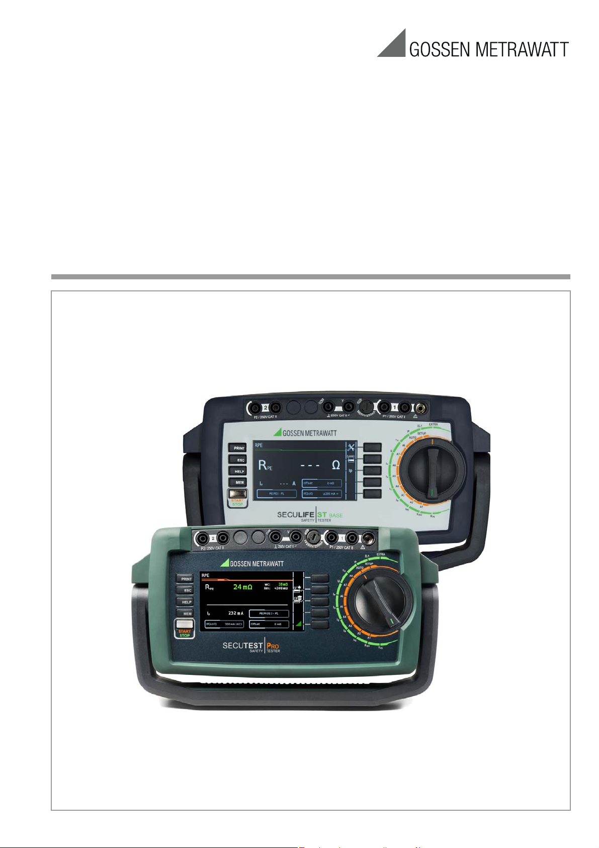
Controls
Rotary selector switch
LCD panel
Single measurements
Sequences A1 ... A8, AUTO
(automatic test sequences)
MEM:
database functions
ESC: back
Fixed Function Keys
HELP: help images
START: start/stop
– Single measurement
– Test sequence
Finger Contact
PRINT: print via USB
Rotary switch level:
Rotary switch level:
Softkeys
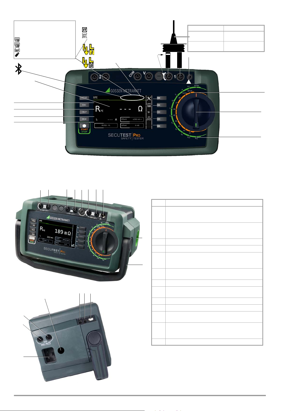
Test Probe
!
Supply power connection SECUTEST CLIP (Z745H)
White identified
and fused high
current path
– For keyboard *
– For Barcode/RFID scanner *
– For printer
– For USB flash drive
Display of symbols for devices
connected to the USB master
interface (see below)
Display of special symbols:
– Measurement at IT system active
– Offset for RPE active
* The receiver must be plugged in here for wireless entry devices.
** Only displayed in case of active connection to another Bluetooth device
Bluetooth®** (feature M01)
Parameters: see page 86
®
Probe Type Applications
Strain relief sleeve,
black
Test current: 200 mA / 10 A
max. 16 A
SK2-25A (Z746C)
Strain relief sleeve,
green
Test current: 200 mA / 25 A
max. 25 A
Mains to test socket
Mains to test socket
N interrupted
orange
green
1
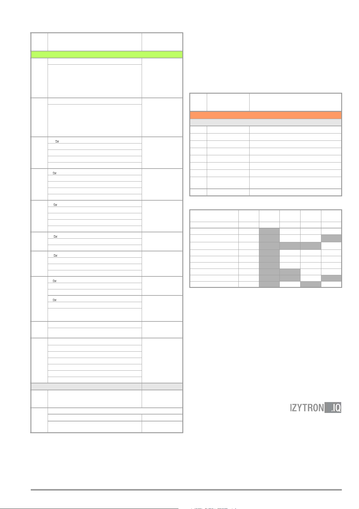
SECUTEST BASE10/PRO (feature G01)
2
A list of suitable devices is included in the appendix (see section 14)
No. Meaning
1
2nd test probe P2 for 2-pole measurement
(only with SECUTEST PRO or instrument with
feature H01)
2
Voltage measuring inputs
(only with
SECUTEST PRO or instrument with
feature I01)
3
Fuse link for probe input P1
4
Test probe connection (P1)
5
Connection (jack socket) for supplying power to
the SECUTEST CLIP (Z745H), see also operating
instructions for leakage current clamp meter
6
Country-specific standard socket (test socket)
for connecting devices under test
7
Carrying handle and tilt stand
8
Country-specific socket for mains power via inlet
plug
9
Fuse link 1 for the mains connection
10
Fuse link 2 for the mains connection
11
Additional fuse link
for 10 A
1
protective conductor test
12
USB master for connecting keyboard, barcode/
RFID scanner
2
, printer 2 and USB flash drive2
(must be FAT32 formatted – not NTFS)
13
USB slave for connection to a PC
3 454
6
7
9
10
8
11
12 13
2211
Connections
These operating instructions describe an instrument with software version FW3.0.0.
2 GMC-I Messtechnik GmbH
Page 3
Overview of the Scope of Functions of the SECUTEST
BASE(10), PRO and SECULIFE ST BASE(25) Test Instruments
Measuring Functions
Test Current/Voltage
Switch
Position
Single measurements, rotary switch level: green
R
R
PE
Section
8.5
Protective conductor resistance
PE
I
Test current (200 mA)
P
SECUTEST BASE10/PRO
and SECULIFE ST BASE 10 A
(feature G01)
and SECULIFE ST BASE25 25 A
1
1
(feature G02)
R
RISO
Insulation resistance (PC I/PC II)
INS
U
Test vo l t a g e
INS
Section
8.6
I
IPE
Section
8.7.1
IB
Section
8.7.2
IG
Section
8.7.3
IA
Section
8.7.4
IP
Section
8.7.5
U
Section
Protective conductor current, RMS
PE
AC component
I
PE~
DC component
I
PE=
Test vo l t a g e
U
LPE
A reference voltage (alternative)
U
Gen
I
Touch current, RMS
T
I
AC component
T~
DC component
I
T=
Test vo l t a g e
U
LPE
Reference voltage (alternative)
U
Gen
I
Device leakage current, RMS
E
AC component
I
E~
DC component
I
E=
Test vo l t a g e
U
LPE
Reference voltage (alternative)
U
Gen
Leakage current from the applied part, RMS
I
A
U
Test vo l t a g e
LPE
Reference voltage (alternative)
U
Gen
I
Patient leakage current, RMS
P
I
AC component
P~
DC component
I
P=
Test vo l t a g e
U
LPE
U
Probe voltage, RMS
Alternating voltage component
U
~
Direct voltage component
U
=
U Measuring voltage, RMS
Alternating voltage component
U
~
U
Direct voltage component
=
2
2
2
8.9
4
ta PRCD time to trip
ta
Section
U
Line voltage at the test socket
8.10
P
LN
Function test at the test socket
for 10/30 mA PRCDs
I Current between L and N
U Voltage between L and N
f Frequency
P Active power
S Apparent power
Section
8.11
PF Power factor
Probe measuring functions
Extension cord with adapter:
EL1
continuity, short-circuit, polarity (wire reversal
Section
8.12
Reserved for expansion within the framework of software updates
EXTRA
Section 9
1
10/25 A-RPE measurements are only possible with line voltages of 115/230 V and
line frequencies of 50/60 Hz.
2
Voltage measuring inputs with SECUTEST PRO or instrument with feature I01) and
SECULIFE ST BASE(25) only
3
Connection of 2nd test probe for two-pole measurement with SECUTEST PRO (or instrument with feature H01) and SECULIFE ST BASE(25) only
4
Measurement of time to trip is not possible in IT systems.
5
No checking for reversed polarity takes place when the EL1 adapter is used.
6
Type of connection not available with
Temperature measurement 2
°C
IZ Current clamp measurement
with the current clamp sensor
SECULIFE ST BASE25
with Pt100 / Pt1000
2
Measurement
Typ e,
Connection Type
PE(TS) - P1 passive
PE(TS) - P1 active
PE(mains) - P1
PE(mains) - P1 clamp
6
P1–P2 3
LN(TS) - PE(TS)
LN(TS) - P1
P1–P2
PE(mains) - P1
PE(TS) - P1
LN(TS) - P1//PE(TS)
Direct
Differential
Alternative
AT3-Adapter
Clamp
Direct
Differential
Alternative (P1)
Permanent connection
Alternative (P1–P2)
Direct
Differential
Alternative
AT3-Adapter
Clamp
Direct (P1)
Alternative (P1)
Perm. con. (P1)
Direct (P1)
Perm. con. (P1)
P1–P2
P1–P2 (with mains *)
* Polarity parameter
V – COM
V – COM (with mains)
Polarity parameter
EL1 adapter
5
)
AT3-IIIE adapter
VL2E adapter
V – COM
V – COM
(feature G02)
6
3
2
2
2
2
Key
Alternative = alternative measurement (equivalent leakage
Differential = differential current measurement
Direct = direct measurement
LN(TS) = short-circuited L and N conductors at test socket
P1 = measurement with test probe P1
P1-P2 = 2-pole measurement with test probes P1 and P2
PE-P1 = measurement between PE and test probe P1
PE(TS) = protective conductor at the test socket
2,
PE(mains) = protective conductor at the mains connection
Switch
Position
Automated test sequences, rotary switch level: orange
Preconfigured (freely adjustable) test sequences – default settings
A1
A2
A3
A4
A5
A6
A7
A8
AUTO
current measurement)
Standard Measurement Type, Connection Type
VDE 0701-0702 Passive measurement type, test socket
VDE 0701-0702 Active measurement type, test socket
VDE 0701-0702-EDV
IEC 62353 (VDE 0751) Passive measurement type
IEC 62353 (VDE 0751) Active measurement type
IEC 60974-4 Connection type: test socket
IEC 60974-4 Connection type: AT16-DI/AT32-DI
VDE 0701-0702
VDE 0701-0702 Active measurement type, test socket
Parameters configuration for EDP (active)
Extension cord measurement type (RPE, RINS), adapter:
EL1
/VL2E/
AT3-IIIE
Differences with Regard to Included Features
SECUTEST...
SECULIFE... — ST BASE —
Touchscreen / keyboard E01 •••
10 A RPE test current
25 A RPE test current
2nd test probe H01 •••
Voltage measuring input *
SECUTEST DB+
SECUTEST DB COMFORT
®
Bluetooth
Antimicrobial housing
* For voltage measurement, or for connecting a current clamp sensor for current
measurement or an AT3 adapter, and for temperature measurement via RTD
Features
BASE PRO PRO BT
comfort
G01
••
G02
I01 •••
KB01 •••
KD01 ••
M01 •
— ST BASE •
Scope of Delivery
Standard Version (country-specific)
1 SECUTEST BASE(10)/PRO or SECULIFE ST BASE(25) test instrument
1 Mains power cable
1 Test probe, 2 m, not coiled
1 USB cable, USB A to USB B, 1.0 m long
1 Plug-on alligator clip
1 KS17-ONE cable set for voltage measuring input (only with
SECUTEST PRO and
1 Calibration certificate
1 Condensed operating instructions
Comprehensive operating instructions available on the Internet
1
1Card with
registration key
SECULIFE ST BASE(25)
for software
or device with feature I01)
—
ST BASE 25
•
GMC-I Messtechnik GmbH 3
Page 4

Contents Page Page
1 Applications ..................................................................... 5
1.1 Table: Types of DUTs – Tests – Standards .....................................5
1.2 Table: Single Measurements – Regulations ....................................5
2 Safety Features and Precautions ..................................... 5
3 General Operation ............................................................ 7
3.1 Measured Value Display .................................................................7
3.2 Language, Keyboard Layout (culture parameter) ..............................7
3.3 Help Functions (HELP key and QR code) ..........................................7
3.4 Entering Alphanumeric Characters ..................................................7
3.5 Print-Outs – Reports ......................................................................7
3.5.1 Multi-Print .....................................................................................7
3.5.2 Report Template for Reading Out Reports to a Thermal Printer or an
HTML File .....................................................................................7
3.5.3 Report Tapes from Thermal Printers ................................................8
3.5.4 Printing via IZYTRONIQ ..................................................................8
3.5.5 Saving Reports to a USB Flash Drive ...............................................8
3.6 Print-Out of ID Labels (as of firmware V1.3.0) ..................................8
3.7 Writing RFID Tags (as of firmware V1.5.0) .......................................8
4 Initial Startup ................................................................... 9
4.1 Connecting the Test Instrument to the Mains ...................................9
4.1.1
Measurements in IT Systems (new parameter as of firmware 1.5.0) .......9
4.1.2 Automatic Recognition of Mains Connection Errors ........................10
4.2 Connecting Test Probe P1 or P2 ...................................................10
4.3 Device Settings ............................................................................11
5 Internal Database ........................................................... 15
5.1 Creating Test Structures, General .................................................15
5.2 Transmitting and Saving Test Structures and Measurement Data ....15
5.2.1 Export – Transmitting Test Structures and Measurement Data from
the Test Instrument to the PC .......................................................15
Import – Uploading Test Structures Created in the Report Generating Pro-
5.2.2
gram to the Test Instrument (only with database extension
“Z853R – SECUTEST DB+”) .........................................................15
5.2.3 Backing Up and Restoring Test Structures and Measurement Data .15
Switching Between 2 Tree Structure Views
5.2.4
SECUTEST PRO
(for
feature KB01, “Z853R – SECUTEST DB+”) ...................................17
5.3 Data Entry ...................................................................................18
5.3.1 Keyboard Entries via Softkeys or External Keyboard ........................18
5.3.2 Data Entry via Touchscreen Keyboard
(only with
5.4 Creating a Test Structure in the Test Instrument, Navigating within
the Structure and Displaying Measured Values ..............................19
5.4.1 General Procedure for Creating Test Structures .............................20
5.4.2 Searching for Structure Elements ..................................................21
5.4.3 Display Measured Values from Saved Tests ...................................21
5.4.4 Clearing the Database ..................................................................21
SECUTEST PRO
and
SECULIFE ST BASE(25)
or test instrument with feature E01) ..........18
or feature KB01,
or for devices with
6 Connecting the Device Under Test ................................. 22
6.1 Residual Current Monitoring .........................................................22
6.2 Reference Voltage L-PE and Alternative Test Sequence ..................22
6.3 Manually Specifying the Connection Type for Single Measurements 22
6.4 Manually Selecting a Connection Type / Protection Category
for Automatic Test Sequences ......................................................22
6.5 Special Conditions .......................................................................23
6.6 2nd Test Probe (only SECUTEST PRO or feature H01) ...................23
6.7 Connection Prompts ....................................................................23
6.8 Connection Tests Conducted by the Test Instrument ......................23
7 Notes on Saving Single Measurements and
Test Sequences ............................................................. 24
7.1 QuickEdit Function – QEDIT
(feature KD01, “Z853S – SECUTEST DB COMFORT”) .....................24
8 Single Measurements .................................................... 25
8.1 General .......................................................................................25
8.2 Meaning of Symbols in the User Interface ....................................26
8.3 Displaying the Last Measured Values ............................................26
8.4 Measurement Series and Storage .................................................26
8.5 Measuring Protective Conductor Resistance – RPE ........................ 27
8.6 Insulation Resistance Measurement – RINS ...................................31
8.7 Measuring Leakage Current .........................................................35
8.7.1 Protective Conductor Current – IPE ...............................................36
8.7.2 Touch Current – IB ...................................................................... 40
8.7.3 Device Leakage Current – IG ........................................................43
8.7.4 Leakage Current from the Applied Part – IA ..................................46
8.7.5 Patient Leakage Current – IP ........................................................47
8.8 Probe Voltage – U .......................................................................50
8.9 Measuring Voltage – U (SECUTEST PRO or feature I01 only) ......... 51
8.10 Measuring Time to Trip for RCDs of the Type PRCD – tA ................52
8.11 Function Test – P ........................................................................ 53
8.12 Testing Extension Cords for Correct Function – EL1 ....................... 54
9 Special Functions – EXTRA ............................................ 56
10 Test Sequences .............................................................. 58
10.1 General .......................................................................................58
10.2 User-Defined Test Sequences / Remote Control
(only with feature KB01, “Z853R – SECUTEST DB+”) ....................59
10.2.1 General .......................................................................................59
10.2.2 Testing of Probe Connection P1 and Probe Fuse P1 ......................59
10.3 General Settings (Setup: auto measurements parameter) ...............59
10.4 Selecting and Configuring a Test Sequence ...................................61
10.5 Connecting the DUT .....................................................................67
10.6 Selecting a Test Object ................................................................67
10.7 Checking Connection and Starting the Test Sequence ....................67
10.8 Executing and Evaluating Test Steps ............................................. 67
10.9 Setting Limit Values Manually .......................................................68
10.10 Ending the Test Sequence ............................................................68
10.11 Saving Test Results ..................................................................... 69
11 Warnings, Error Messages and Notes ............................ 70
11.1 List of error messages ................................................................. 71
11.2 List of Possible DUT Connections
Depending on Measurement Type ...............................................79
12 Characteristic Values .................................................... 80
13 Maintenance .................................................................. 83
13.1 Housing Maintenance .................................................................. 83
13.2 Testing the Color Display and the Buzzer (self-test parameter) ........83
13.3 Software Update (system info parameter) ......................................83
13.4 Backup Battery for Real-Time Clock ..............................................83
13.5 Fuse Replacement ....................................................................83
13.6 Recalibration ...............................................................................83
13.7 Technical Safety Inspections ........................................................83
13.8 Returns and Environmentally Sound Disposal ................................84
14 Appendix ........................................................................ 84
14.1 List of Suitable Printers with USB Port ........................................... 84
14.2 List of Suitable Barcode Scanners and RFID Scanners with
USB Port .....................................................................................85
14.3 Use of USB Storage Devices ......................................................... 85
14.4 Bluetooth Interface (SECUTEST PRO BT (comfort) or feature M01) 86
14.5 Remote Control Interface .............................................................86
14.6 Entry Via an External USB Keyboard .............................................. 87
14.6.1 Additional Key Functions, DB Comfort Option
(feature KD01, “Z853S – SECUTEST DB COMFORT”) ....................87
14.7 Index ..........................................................................................88
4 GMC-I Messtechnik GmbH
Page 5
15 Repair and Replacement Parts Service
Attention!
!
Note
Note
Attention!
!
Calibration Center and Rental Instrument
Service ............................................................................90
16 Product Support ............................................................. 90
1 Applications
1.1 Table: Types of DUTs – Tests – Standards
Testing after Repairs /
Periodic Testing
Test DUTs
in accordance with
the following standards
EN 50678, draft
DIN VDE 0701-0702
IEC 62353
DIN EN 62353
(VDE 0751-1)
IEC 60974-4
DIN EN 60974-4
VDE 0544-4
Electric devices •
Work devices •
Mains operated electronic devices
Hand-held electric tools •
Extension cords •
Household appliances •
Data processing devices •
Medical electric
devices, applied parts
Welding units •
•
•
2 Safety Features and Precautions
SECUTEST BASE(10), SECUTEST PRO and SECULIFE ST BASE(25) test
instruments fulfill all requirements of applicable EU directives and
national regulations. We confirm this with the CE mark.
The relevant declaration of conformity can be obtained from
GMC-I Messtechnik GmbH.
The test instruments are manufactured and tested in accordance
with the following safety regulations: IEC 61010-1 / DIN EN
61010-1 / VDE 0411-1,
Safety of the operator, as well as that of the test instrument and
the device under test, is only assured when it’s used for its
intended purpose.
Read the operating instructions carefully and completely before placing your
test instrument into service. Follow all instructions contained therein. Make
sure that the operating instructions are available to all users of the instrument.
Tests may only be performed by a qualified electrician, or under the
supervision and direction of a qualified electrician.The user must be
instructed by a qualified electrician concerning performance and evaluation of the test.
Suitable personal safety equipment is required.
If you use active or passive body assistance, please consult your
physician or the manufacturer of the body assistance device.
Manufacturers and importers of medical electric devices must
provide documentation for the performance of maintenance by
trained personnel.
DIN EN 61557-16/VDE 0413-16
The test instrument may not be used for measurements
within electrical systems! The test instrument must be
operated within the same electrical system as the test
object!
Test sequences for VDE 0701-0702, ÖVE 8701 and
SNR 462638 are identical. In the interest of improved readability, only VDE 0701-0702 is described below. The explanations apply to ÖVE 8701 and SNR 462638 as well. The
instrument can be switched to the country-specific standard designation in SETUP (page 1/3) under “Auto Measurements”, “Measuring Sequence Parameters”.
1.2 Table: Single Measurements – Regulations
Single measurements
per Regulation
EN 50678, draft
Protective conductor resistance •
Insulation resistance
Protective conductor current
Primary leakage current
Device leakage current
Touch current
Current from welding circuits
Patient leakage current
Leakage current from the applied part
Test methods
Alternative measuring method (equivalent
(device) leakage current)
Differential current measuring method
Direct measuring method
•••
•
••
••
•••
•••
Key
• Specified test
DIN VDE 0701-0702
IEC 62353
DIN EN 62353
••
•
•
•
Observe the following safety precautions:
•
The instrument may only be connected to TN, TT or IT electrical
systems with a maximum of 240 V which comply with applicable
safety regulations (e.g. IEC 60346, VDE 0100) and are protected
with a fuse or circuit breaker with a maximum rating of 16 A.
• Measurements within electrical systems are prohibited.
Be prepared for the occurrence of unexpected voltages at
•
under test
(for example, capacitors can be dangerously charged).
• Make certain that the measurement cables are in flawless condition, e.g. no damage to insulation, no cracks in cables or plugs
etc.
• When using a test probe with coil cord (SK2W):
Grip the tip of the test probe firmly, for example if it has been
inserted into a jack socket. Tensioning at the coil cord may
otherwise cause the test probe to snap back resulting in possible injury.
• Measurement of insulation resistance and equivalent leakage current
(alternative leakage current measuring method)
Testing is conducted with up to 500 V. Current limiting is utilized (I < 3.5 mA), but if terminals L or N at the test socket or
the test probe are touched, electrical shock may occur which
could result in consequential accidents.
(VDE 0751-1)
IEC 60974-4
DIN EN 60974-4
VDE 0544-4
• Leakage current measurement while connected to line voltage
It’s absolutely essential to assure that the device under test is
operated with line voltage during performance of the leakage
current measurement. Exposed conductive parts may con-
•
duct dangerous touch voltage during testing, and may not
under any circumstances be touched.
(Mains power is discon-
nected if leakage current exceeds approx. 10 mA.)
•
The function test may only be performed after the DUT has
successfully passed the safety test!
devices
GMC-I Messtechnik GmbH 5
Page 6
• Probe Test
Attention!
!
Attention!
!
Attention!
!
!
®
Test the probe after completing each test (see also section 10.2.2).
If the fuse at test probe P1 is defective after testing has
been started, all subsequent measurements conducted
using this measuring path will be incorrectly evaluated as
good!
• Fuse Replacement
The fuses may only be replaced when the instrument is voltage-free, i.e. the instrument must be disconnected from
mains supply power and may not be connected to a measuring circuit. The fuse type must comply with the specifications
in the technical data or the labeling on the instrument.
Opening the Instrument / Repairs
The instrument may only be opened by authorized, trained personnel in order to ensure flawless operation and to assure that the
guarantee is not rendered null and void.
Even original replacement parts may only be installed by authorized, trained personnel.
If it can be ascertained that the instrument has been opened by
unauthorized personnel, no guarantee claims can be honored by
the manufacturer with regard to personal safety, measuring accuracy, compliance with applicable safety measures or any consequential damages.
If the guarantee seal is damaged or removed, all guarantee claims
are rendered null and void.
Safer Testing with Test Adapter
In the case of test objects for which a starting current of greater
than 30 A can be expected, we urgently recommend the use of a
test adapter for larger starting currents:
for example test adapters from the AT3 series
(AT3-IIIE, AT3-IIS, AT3-IIS32, AT16DI or AT32DI).
Alternative: Passive Test
If necessary on the basis of the hazard assessment, testing can
be conducted as a passive test (equivalent leakage current
method), i.e. without switching line voltage to the test socket.
The test instrument may not be used:
• If external damage is apparent, for example if parts which
conduct dangerous touch voltage are freely accessible, if the
display is broken or defective (in which case dangerous voltage or mains connection errors might no longer be indicated)
• If the seal or sealing lacquer has been removed as the result
of repairs or manipulation carried out by an unauthorized/noncertified service provider
With damaged connection and/or measurement cables and patient
•
ports, e.g. interrupted insulation or kinked cable
•If the instrument no longer functions flawlessly
• After extraordinary stressing due to transport
In such cases, the instrument must be removed from operation
and secured against unintentional use.
Meanings of Symbols on the Instrument
The symbols on the instrument have the following meanings:
Before opening the housing, pull the mains plug out of
the outlet and wait for at least 5 minutes.
Switching Power Consumers – Procedure
Be absolutely sure to adhere to the sequence specified below
when switching the live device under test. This prevents excessive
wear of the mains relays at the test instrument.
Before measurement:
1
Device under test: Turn the DUT off via its own switch.
2 Test instrument:
3
Device under test: Turn the DUT on via its own switch.
After measurement:
4
Device under test: Turn the DUT off via its own switch.
5 Test instrument:
Switch line voltage to the test socket.
Deactivate line voltage to the test socket.
Switching Loads – Maximum Starting Current
Our SECUTEST BASE(10), PRO and SECULIFE ST BASE(25) test instruments permit active testing of devices with a nominal current (load
current) of up to 16 A.
The test socket on the respective test instrument is equipped with
16 A fuses to this end and the switching capacity of the internal
relays is also 16 A. Starting current of up to 30 A is permissible.
Warning regarding dangerous electrical voltage
Warning concerning a point of danger
(attention: observe documentation!)
CE conformity marking
This device may not be disposed of with household
trash.
Further information regarding the WEEE mark can be
accessed on the Internet at www.gossenmetrawatt.com by entering the search term “WEEE”.
If the guarantee seal is damaged or removed, all guarantee claims are rendered null and void.
Utilized Trademarks
QR Code QR Code is a registered trademark of
DENSO WAVE INCORPORATED
®
The Bluetooth
trademarks of Bluetooth SIG, Inc
word mark and logo are registered
Despite extensive protective measures targeted at preventing overloading, the relay contacts may be welded
together if starting current exceeds 30 A. The following error
message appears in this case.
“L(N) test socket fuse defective”.
➭ Check both of the mains connection’s fuse links. If they’re de-
fective replace them with new ones.
If the error message described above still appears, it must be
assumed that the relay is defective. If this is the case, the test
instrument must be sent to our service department for repair (see
section 15 for address.
6 GMC-I Messtechnik GmbH
Page 7

3 General Operation
Note
Note
Note
Note
Note
3.1 Measured Value Display
The following items appear at the display panel:
• The selected measuring function or standard
• Measured values with abbreviations and units of measure
• Setting parameters such as type of connection and measurement type
• Symbols for softkey operation
• Wiring diagrams, notes regarding the test sequence
and error messages
Green progress bars appear in the header for single measurements, and orange progress bars appear for test sequences.
If the upper range limit is exceeded, the upper limit value is displayed and is preceded by the “>” symbol (greater than), which
indicates measurement value overrun. Falling short of the lower
range limit is indicated by the “<” symbol (less than), for example
with RINS.
The depiction of LEDs in these operating instructions
may vary from the LEDs on the actual instrument due to
product improvements.
Measured Value Storage
See section 8.4
3.2 Language, Keyboard Layout (culture parameter)
The desired user interface language, a country-specific keyboard
layout and a language for the test sequences (measuring
sequence parameter) can be selected in the SETUP switch setting
(see Section 4.3).
If you change the keyboard layout setting, you’ll be
prompted to scan in certain barcodes. This is necessary
in order to assure that the barcode reader still works correctly after changing the language. If the barcode reader
isn’t currently available, you can subsequently set it to the
new keyboard layout via Setup (2/3) > External Devices >
Barcode Reader > Type Z751A.
3.3 Help Functions (HELP key and QR code)
Depending on the rotary selector switch position and the selected
measurement type, appropriate wiring diagrams are displayed.
➭ Press the HELP key in order to query online help.
➭ Press the ESC key in order to exit online help.
3.4 Entering Alphanumeric Characters
Entry via the Keyboard
In addition to the softkey keyboard which can be accessed at the display, USB keyboards (with USB boot keyboard profile) can also be
used to enter texts such as offsets, ID numbers, type designations
and comments (see also section 5.3).
Reading in Barcodes
➭ Correct recognition of the barcode scanner by the test instru-
ment after connection to the USB port is indicated by the
icon in the header.
➭ Select the following parameter in order to configure the bar-
code scanner for initial start-up:
Setup (2/3) > External Device > Barcode Scanner > Type
Z751A.
➭ Scan the barcode which then appears.
When the menu for alphanumeric entry via the softkey keyboard
is open at the display, any value read in by means of a barcode
scanner is directly accepted.
See the appendix in section 14.2 concerning available accessory
devices.
We’re unable to offer any guarantees regarding the use of
scanning devices other than those listed in the appendix.
Reading In an RFID Code
➭ Correct recognition of the RFID scanner by the test instrument
after connection to the USB port is indicated by the icon in
the header.
When held at a distance of about 3 cm directly in front of the middle of the RFID tag, the tag’s current content is read (e.g. the ID
code) and the SCAN LED on the reader blinks.
If the database view (MEM) is active (before or after a measurement), the cursor automatically jumps to the DUT with the corresponding ID code.
If the object is not found, a prompt appears asking if you would
like to create a new object.
3.5 Print-Outs – Reports
If you’ve connected a suitable printer (see list in appendix in section 14.1) or USB flash drive via the USB master port, you can
read out a test report for each completed single measurement or
test sequence by pressing the PRINT key.
The respective single measurement or test sequence must be
previously selected in the memory menu with the help of the scroll
keys.
We’re unable to offer any guarantees regarding the use of
printers other than those listed in the appendix.
3.5.1 Multi-Print
If, in the memory menu, you move the cursor to a test object for
which several tests have been conducted (individual measurements or test sequences) and press the PRINT key, a combined
test report with all test results for the respective test object is read
out.
3.5.2 Report Template for Reading Out Reports to a Thermal Printer or an HTML File
A report can be read out concerning the results of individual measurements or test sequences stored to the internal database. A
report template is permanently stored to the test instrument for
this purpose. The designation of the standard in the report may
vary depending on which test sequence has been conducted.
The report template includes the following items:
•ID number
• Designation
• Customer name
• Location
•Date
•Time
• Comment with 64 characters
• Standard designation / sequence name / manual test
• Measured values
• Limit values
•Evaluations
• Test equipment (serial number)
The display which appears is not a print preview and
does not reflect the actual appearance of the printout.
GMC-I Messtechnik GmbH 7
Page 8

3.5.3 Report Tapes from Thermal Printers
Note
Note
Note
Note
Note
Note
Note
Report tapes can be printed out with the Z721S thermal printer
(accessory: Z722S thermal paper).
As of firmware V2.1.1: The test report can now be edited and a
company logo can be added to it directly in SETUP at the test
instrument (see page 14). A company logo can be loaded from a
USB flash drive for which the following image file formats are supported:
BMP, JPG, PNG or GIF, resolution: max. 800 x 800 pixels. Color
depth: max. 24-bit.
Report Designer PC software is no longer supported as a
firmware version 2.1.1.
3.5.4 Printing via IZYTRONIQ
Alternatively, stored measurement data can be read into IZYTRONIQ report generating software at a PC and printed out as a
report.
Code Recognition
Please make sure that the printed codes are recognized
by your scanner. Some code types have to be activated
on your scanner prior to being used (this is frequently the
case with Aztec/DataMatrix).
Minimum Width of Labels
Tape cartridges with a minimum width of 12 mm are recommended for print-out of 2D code labels (QR code,
MicroQR code, DataMatrix, Aztec).
If a blank label is discharged upon printing an ID number
as a 2D code with a 9 mm ribbon cartridge, replace it
with a 12 mm cartridge (or wider) and restart the printing
process.
3.5.5 Saving Reports to a USB Flash Drive
Select a measurement from the database view (MEM key) with the
scroll keys, for which a report will be saved to a USB flash drive.
Then press the PRINT key. “Print job finished” appears. The report
is written to an HTML file. The filename consists of the timestamp
and the ID of the test object.
Alternatively, reports can be save or printed out immediately after
conducting a test, or when the test list view is open.
A list of suitable USB flash drives is included in the appendix
(see section 14).
3.6 Print-Out of ID Labels (as of firmware V1.3.0)
A barcode printer permits for the following applications:
• Print-out of ID numbers encrypted as barcodes for devices
under test – for quick and convenient acquisition during periodic testing
• Print-out of repeatedly occurring designations such as test
object types encrypted as barcodes in a list, allowing them to
be read in as required for comments
We’re unable to offer any guarantees regarding the use of
printers other than those listed in the appendix.
3.7 Writing RFID Tags (as of firmware V1.5.0)
The following function is made possible by an RFID scanner (programmer):
• Read-out of encrypted ID numbers for devices under test to
an RFID tag for quick and convenient read-in during periodic
testing
If you’ve connected a suitable RFID scanner (see list in appendix
in section 14.1) via the USB master port, you can write an RFID
tag for each
➭ Correct recognition of the RFID scanner by the test instrument
after connection to the USB port is indicated by the icon in
the header.
➭ Switch to the database view (MEM key).
➭ Select the desired
new test object by means of its ID.
➭
Briefly press the
➭ You’re prompted to hold the scanner at a distance of about
3 cm directly in front of the middle of the RFID tag.
The “Successful write” message appears to indicate that the procedure has been completed.
test object
An error message appears if the ID cannot be converted to
an
RFID tag
by pressing the PRINT key:
test object
PRINT
key on the test instrument.
.
with the scroll keys or enter a
If you’ve connected a suitable barcode printer (see list in appendix
in section 14.1) via the USB master port, you can print out a barcode for each
➭ By viewing the printer information, you can first of all deter-
mine whether or not the connected barcode printer is correctly recognized by the test instrument:
Setup (2/3) > Printer > Z721D > Printer Information
or
Setup (2/3) > Printer > Z721E > Printer Information
➭ Select encryption in Setup (paper size is set automatically as
of FW 2.0):
Setup (2/3) > Printer > Z721D > Printer Settings
or
Setup (2/3) > Printer > Z721E > Printer Settings
➭ Switch to the database view (MEM key).
➭
Select the desired test object with the scroll keys.
➭ Press the PRINT key.
➭
Depending on your selection, the ID is printed onto the label as a
barcode. An error message appears if the ID cannot be read out
as a barcode or a 2D code.
8 GMC-I Messtechnik GmbH
test object
by pressing the PRINT key.
We’re unable to offer any guarantees regarding the use of
readers or writers other than those listed in the appendix.
Page 9
4 Initial Startup
Attention!
!
L1
N
Green-yellow
Green-yellow
PE
L1
L2
L3
N
PE
L1
L2
L3
N
Green-yellow
KS13
When selecting
between two
states: direct
change without
submenu
Icon Toggle
4.1 Connecting the Test Instrument to the Mains
➭ See section 12 for nominal mains values (nominal ranges of
use).
➭ Connect the test instrument to the mains cable via its inlet
plug and insert the mains plug into an electrical outlet. The
function selector switch can be set to any position.
If a mains outlet (earthing contact outlet) is not available, or if
only a 3-phase outlet is available, the adapter socket can be
used to connect the phase conductor, the neutral conductor
and the protective conductor. The adapter socket has three
permanently attached cables and is included with the KS13
cable set.
If connection is not possible via an earthing contact outlet: Shut down mains power first.
Then connect the cables from the coupling socket to the
mains using pick-off clips in accordance with the diagram.
Disconnection from mains power is only possible via the
mains plug.
4.1.1 Measurements in IT Systems (new parameter as of firmware
1.5.0)
The IT system
setting can be
activated for all
single measure-
ments and test sequences in the SETUP switch position (Setup 1/
3) in the All measurements submenu (in this case the icon
appears in the header of each display page):
with “Measurement at IT system” set to Yes: active leakage current
measurements (or all measurements with reference to PE at the
mains connection side) are disabled. Test sequences which
include measurements of this sort are also disabled.
If, when being connected to line voltage, the SECUTEST detects
a change at PE as compared with the previously used mains connection, the inspector is asked directly after initial start-up if the
currently used outlet belongs to an IT system. The IT system
option in SETUP is activated based on the user’s answer. If “Measurement at IT system” is activated, this is indicated by the
icon in the header.
Regardless of this, it’s always possible to accordingly change the
option manually in SETUP.
The setting for the “Measurement at IT system” option is retained
even after disconnection from the mains.
In IT systems, active leakage current measurements (or any measurements with reference to PE at the mains connection side) do
not deliver reliable measured values, for which reason all single
measurements of this sort, as well as test sequences which
include this type of measurement, are disabled when the “Measurement at IT mains” option has been activated in SETUP.
Figure 1 Connecting the Test Instrument to the Mains
The Meas. at IT mains parameter can be set in Setup:
Setup 1/3 > All Measurements > Meas. at IT Mains
GMC-I Messtechnik GmbH 9
Page 10
4.1.2 Automatic Recognition of Mains Connection Errors
Note
Attention!
!
Note
Note
The device automatically recognizes mains connection errors if
the conditions in the following table have been fulfilled. The user is
informed of the type of error, and all measuring functions are disabled in the event of danger.
Typ e o f Mai n s
Connection Error
Voltage at
protective conductor PE
to finger contact
(START/STOP key)
Protective conductor PE
and
phase conductor L
reversed and/or
neutral conductor N
interrupted
Line voltage
< 180 V / < 90 V
(depending on mains)
Test for IT/TN system
1
10/25 A-RPE measurements are only possible with line voltages of 115/230 V and
line frequencies of 50/60 Hz.
2
If the user of the test instrument is too well insulated, the following error message may
appear: “Interference voltage at mains connection PE”
Message Condition Measurements
Pres s START/STOP
Display at the
instrument
Display at the
instrument
button
U > 25 V
Key → PE:
2
< 1 MΩ
Voltage at PE
> 100 V
U
< 180 V
L-N
U
<90V
L-N
Connection
N → PE
> 20 kΩ
All measurements
disabled
Not possible
(no supply power)
Possible under
certain circum-
stances
Possible under cer-
tain circumstances
1
4.2 Connecting Test Probe P1 or P2
Insert the double plug from test probe P1 or P2 into socket 1 or 2
respectively such that the plug with the white ring makes contact
with the socket with the vertical bar.
The white ring identifies the terminal for the high current conductor which is safeguarded by the neighboring fuse link.
Difficultly in contacting exposed conductive parts
when using the standard probe with test tip
In order to assure good contact, surface coatings must
be removed from devices under test with special tools at
a suitable location.
The tip of test probe P1 is not suitable for scratching away
paint, because this may impair its coating and/or mechanical strength. Brush probe Z745G may be more suitable than
the test probe in certain individual cases.
Finger Contact
During this test for correct mains connection, a voltage
measurement is performed between the finger contact
and PE at the test instrument’s mains connection, and its
reference potential is acquired via the user’s body resistance to the conductive start key. In order to obtain reliable measurement results, this resistance value must be
less than 1 MΩ. If the user is wearing insulating shoes or
gloves, or is standing on an insulating floor covering,
erroneous measurements and display of the “Interference
voltage at mains connection PE” message may result. Try
to reduce resistance in this case, for example by touching
ground potential with the other hand (e.g. a radiator, but
not an insulating wall etc.).
If, while testing protective conductor potential, you determine that the mains protective conductor is carrying voltage
(in accordance with the first two mentioned cases), no
further measurements may be performed with the test instrument. If this is the case, potentially dangerous voltage is
also present at the accessible earthing contacts of the
standard socket (test socket). Immediately disconnect
the test instrument from the mains and arrange to have
the fault eliminated at the mains connection.
Voltage at the electrical system’s protective conductor PE may
result in distorted measurement values during testing for
the absence of voltage, or during leakage voltage measurements.
10 GMC-I Messtechnik GmbH
Page 11
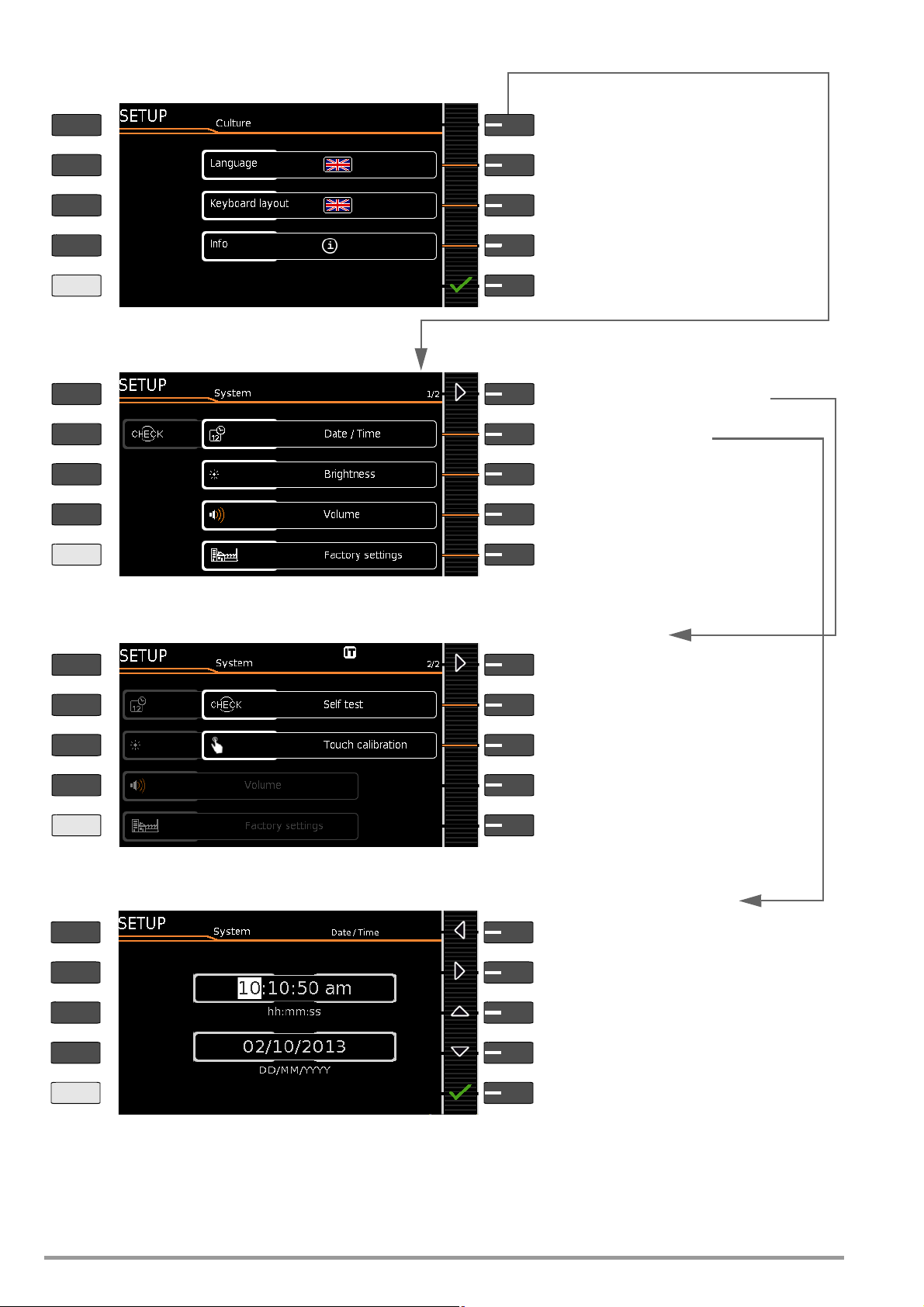
4.3 Device Settings
SETUP
Display additional menu pages
Menu selection for operating parameters, page 1 of 3
Clear database or display statistics,
Set date/time, volume, and brightness
Display additional menu pages
Menu selection for operating parameters, page 2 of 3
Add, select, delete or protect inspector
Select language for user interface and keyboard
For example, select and configure barcode scanner
Display additional menu pages
Menu selection for operating parameters, page 3 of 3
(see submenu on following page)
Keys with fixed functions
Softkeys = keys with functions that vary
depending on the operating level
PRINT
ESC
HELP
MEM
PRINT
ESC
HELP
MEM
PRINT
ESC
HELP
MEM
Setup 1/3
Setup 2/3
Setup 3/3
(see following page).
Save only appears if a USB flash drive is plugged in
by scanning the displayed barcode
Enable functions, display extras
Only with database extension or feature KB01:
Manage and import own sequences
with password (see note in this regard below)
Set test sequence parameters: amongst others measuring sequences (standard) (see section 10.3)
Parameters for single measurements and test
sequences (see section 4.1.1 and section 6.2)
Menus for using the Bluetooth interface
(see section 14.4) (only with feature M01)
To submenu for selecting and setting up a printer
(see page 14)
Query software/hardware version, serial no.,
Calibration data, memory occupancy, user’s manual *
* QR code with link to current operating instructions on the web
For the purpose of initial start-up, we recommend
setting the following basic parameters in the order
shown at the right:
Setup 2/3 > Culture > Language (for user interface)
Setup 2/3 > Culture > Keyboard Layout (for alphanumeric entries)
Setup 1/3 > System > Date / Time (for report generation)
Setup 1/3 > System > Brightness (display brightness as %)
Setup 1/3 > Auto Measurements
> 2/2 > Initial Window Style: Tree or Detail View
Figure 2 Device Settings, Main Menu Level – SETUP Switch Setting
The following parameters are advisable for maintenance purposes:
SETUP 3/3 > Test > Display / Buzzer (for checking info and warning
displays/signals)
SETUP 3/3 > System Info > Software Version for updates (see sec-
tion 13.3) and Calibration Data for adjustment, last and next calibration (see notes on bottom of page 12).
See section 13.3 regarding downloading the latest software version.
Notes Concerning the Inspector Parameter
– The inspector who has just been “selected” appears in tests
to be conducted as “Inspector”. None of the SECUTEST settings are stored specifically for the inspector – all settings in
GMC-I Messtechnik GmbH 11
the SECUTEST are stored for the respective device and are
available to all inspectors.
–
If an inspector is password-protected
know the password from “selecting” this inspector. There’s
word prompt when the test instrument is started up.
remains selected even in the event of a power failure – a
(password-protected) inspector can only be unselected by
selecting another inspector.
As of firmware 1.6.0: In order to delete an inspector whose
password you don’t know, it’s sufficient to enter an incorrect
password five times in a row and to confirm the entry each
time – a query then appears as to whether or not the inspector should be deleted. The inspector to be deleted may not be
the same as the currently selected inspector.
, this only prevents users who don’t
no
pass-
The inspector
Page 12
Manual selection for language and keyboard layout
PRINT
ESC
HELP
MEM
PRINT
ESC
HELP
MEM
PRINT
ESC
HELP
MEM
Select language for user interface
Country-specific keyboard layout
Jump back to next higher menu level
To parameter for default values
Menu selection for date, volume and brightness
Date and time setting menu
Volume setting menu
Brightness setting menu for LCD
To parameters
Default settings
Self-test for display and buzzer
PRINT
ESC
HELP
MEM
Move cursor left
Set time and date menu
Move cursor right
Increase number
Decrease number
Accept changes and jump back
See settings menu below
Setup 2/3 > Culture
Setup 1/3 > System 1/2
Setup 1/3 > System 2/2 > Default Settings
Setup 1/3 > System 1/2 > Date / Time
Page 2/2: Information on date format,
Messages, user interface, measurements
for USB or touchscreen keyboard
With SECUTEST PRO only (feature E01):
Calibrate touchscreen keyboard
Select language for user interface
Info: Date format, decimal separator *
Reset to default values
Caution: The setup configurations
are deleted! (also deletes list of inspectors,
database content and company logo
)
decimal separator
Figure 3 Device Settings, Submenu Level – SETUP Switch Setting
Notes on Calibration Data (adjustment, calibration)
SETUP 3/4 > System Info 2/6 > Calibration Data:
Whereas data for the last adjustment and calibration were set at
the calibration center, date and time of the next calibration (recalibration date) can be changed by the user, if necessary, by select-
12 GMC-I Messtechnik GmbH
ing the EDIT button as shown in the example above for setting
system time.
* As of firmware version 1.7.0, the “Measuring Sequences” parameter for the selec-
tion of country-specific standards (VDE, OVE and NEN) can be found
in SETUP 1/3 under “Auto measurements 2/2”.
Page 13
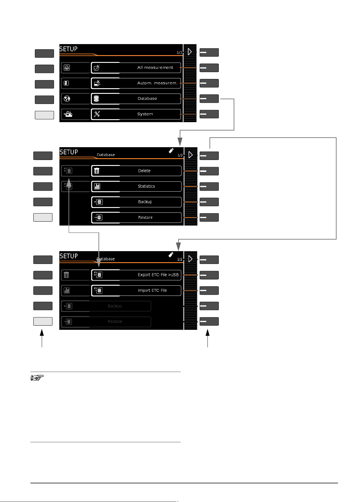
Database Functions
Note
Display additional menu pages
Menu selection for database functions, page 1 of 2
Display database statistics
Only with inserted USB drive:
Only with inserted USB drive:
Display additional menu pages
Menu selection for database functions, page 2 of 2
Keys with fixed functions
Softkeys = keys with functions that vary
depending on the operating level
PRINT
ESC
HELP
MEM
PRINT
ESC
HELP
MEM
Setup 1/3
Database 1/2
Database 2/2
Backup database to USB flash drive (
FAT32
formatted)
Restore database from USB flash drive
Delete database content (but not its structure)
Note: Data are irretrievably deleted!
* Z853R or feature KB01
Only with database extension * and inserted USB
drive: Import a database from a “.secu” file which has
been created specifically for the SECUTEST/
SECULIFE ST with
IZYTRONIQ
.
Only with database extension * and inserted USB drive:
Export database (“.secu” file **)
**
Compatible with IZYTRONIQ
PRINT
ESC
HELP
MEM
GMC-I Messtechnik GmbH 13
Modification of the file format
Direct import of data in the old file format (“.etc” file extension) is no longer possible as of firmware version
02.01.00.
Import the data into IZYTRONIQ report generating software
first and then convert them to the new “.secu” file format.
These data can then be imported to your test instrument
with the help of a USB flash drive.
Backup files (.etcbak) from previous firmware versions
are still compatible.
Page 14
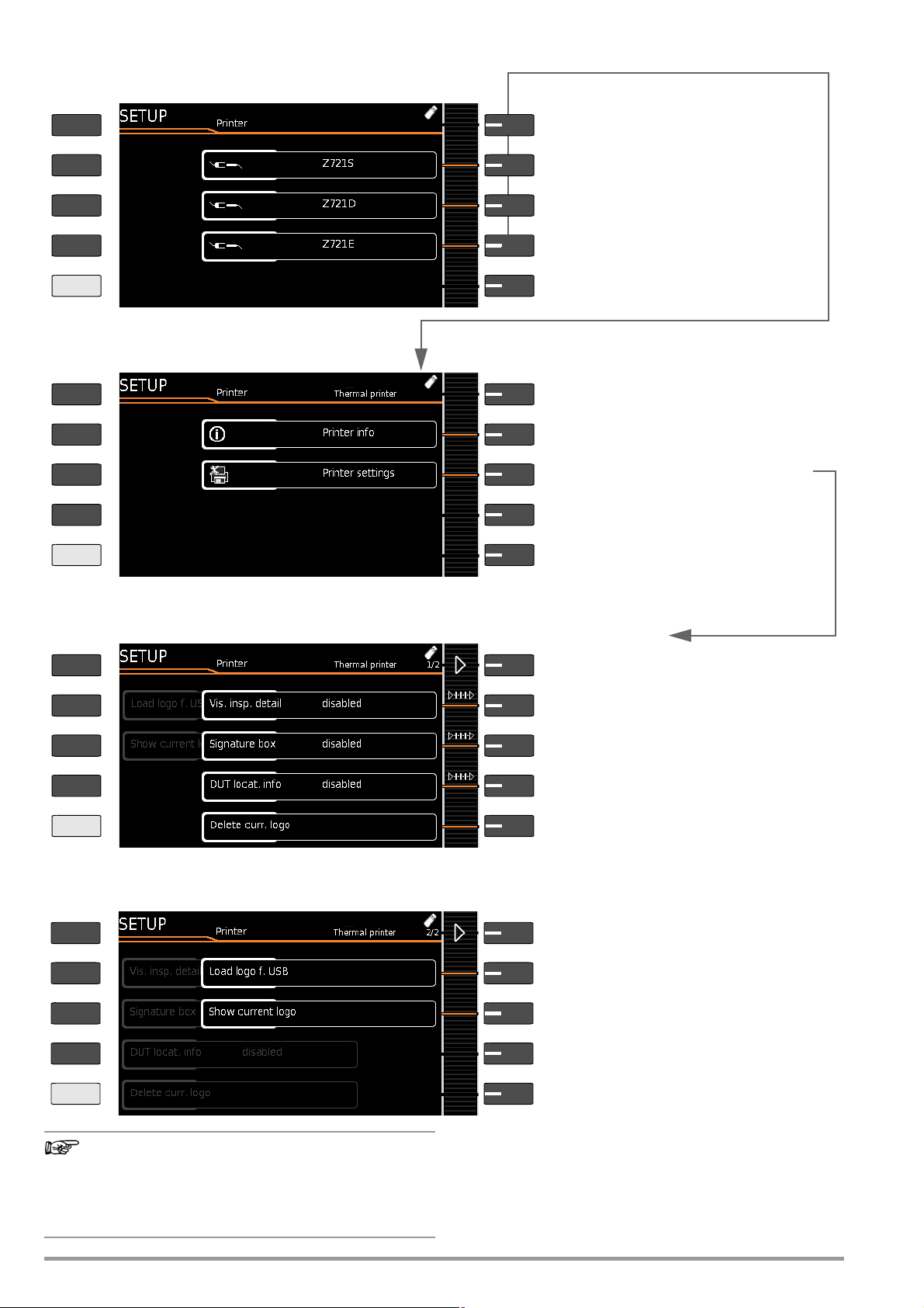
Printer Functions – Selection and Settings Using the Thermal Printer as an Example
Note
Select the connected printer
PRINT
ESC
HELP
MEM
PRINT
ESC
HELP
MEM
PRINT
ESC
HELP
MEM
Retrieval of information or settings
Setting parameters
PRINT
ESC
HELP
MEM
Setup 2/3 > Printer
Setup 2/3 > Printer > Z721S
Thermal Printer > Settings1/2
Thermal Printer > Settings 2/2
Z721E * printer: Barcode label printer
Printer info / printer settings
* For testing instrument firmware as of 1.8.3
Z721D * printer:
Printer info / printer settings
*Phase-out model
Z721S printer: Printer info / printer settings
Printer settings:
Parameters depend on printer type
Printer info: Name, status, type
Switch to page 2/2
Visual inspection details: show/hide
Signature field: show/hide
Location information: show/hide
Delete a (company) logo previously loaded from a
USB flash drive (see Settings 2/2).
Load and display a logo from a USB flash drive
Switch to page 1/2
Load a (company) logo from an inserted USB flash
drive: Selection list is displayed
Display the currently loaded logo.
Prerequisites for loading a logo:
Format: BMP, JPG, PNG or GIF, resolution: max.
800 x 800 pixels. Color depth: max. 24-bit.
Report Designer PC software is no longer supported as of
firmware version 2.1.1. The test report can now be edited
and a company logo can be added to it (only with thermal
printer Z721S) directly in SETUP at the test instrument
(see above).
14 GMC-I Messtechnik GmbH
Page 15
5 Internal Database
Attention!
!
Attention!
!
Note
Note
Attention!
!
Attention!
!
5.1 Creating Test Structures, General
A complete test structure with data regarding customer properties, buildings, floors, rooms and test objects can be created in
the test instrument. This structure makes it possible to save the
results of single measurements or test sequences to test objects
belonging to various customers. Manual single measurements
can be grouped together into a so-called “manual sequence”.
Objects can be identified with the following parameters (boldface
parameters are mandatory entry fields):
•
Device (ID, designation, location, test interval *, type, manufacturer,
comment, serial number, protection category, cost center
*
)
ment
ME device ** (ID
•
turer, comment, serial number, protection category, number of type
B application parts **,
number of type BF application parts **, number of type CF ** application parts, cost center, department, UDI **, mains connection **)
• Room * (ID and designation)
• Floor * (ID and designation)
• Building * (ID, designation, street, ZIP code and city)
• Property * (ID and designation)
• Customer (ID, designation, street, ZIP code and city)
* Only with database extension, feature KB01, “Z853R – SECUTEST DB+”
** Only with feature KD01, “Z853S – SECUTEST DB COMFORT”
, designation,
customer
, test interval *, type, manufac-
Key
ID = identification number
5.2 Transmitting and Saving Test Structures and Measurement
Data
The following functions are possible (as far as the test instrument
is concerned):
• Export: Transfer a structure including measured values from
the test instrument to the PC (ETC *** or IZYTRONIQ) (see sec-
tion 5.2.1).
• Import *: Transfer a test structure from the PC (ETC *** or
IZYTRONIQ) to the test instrument (see section 5.2.2).
• Backup *: Back up a database to a USB flash drive plugged
into the test instrument (must be FAT32 formatted – not NTFS)
(see section 5.2.3).
• Restore *: Restore a database to the test instrument from a
USB flash drive plugged into the test instrument (must be
FAT32 formatted – not NTFS) (see section 5.2.3).
• Reports: Save reports to a USB flash drive (see section 3.5.5).
* Only with database extension, feature KB01, “Z853R – SECUTEST DB+”
*** Communication with ETC is no longer supported as of firmware version 2.0.0.
If no USB flash drive has been plugged in, the above listed functions are grayed out and disabled.
In order to transfer structures and data, the test instrument and
the PC must be connected with a USB cable or a USB flash drive
must be available.
Please observe the following safety precautions:
During data transmission via the USB port (USB connection to the PC or connection of a USB flash drive), neither
the interface cable nor the USB drive may be disconnected.
*
, depart-
Data transfer to the PC should not be started during single measurements or test sequences.
5.2.1 Export – Transmitting Test Structures and Measurement Data from the Test Instrument to the PC
Structures set up in, and measurement data saved to the test
instrument can be exported to IZYTRONIQ report generating software via a connected USB flash drive (only with data base extension or feature KB01, “Z853R – SECUTEST DB+”), or via the USB
slave port. Select Export IZY file under Setup > Database 2/2 to
this end. The data are converted to an IZYTRONIQ-compatible format with the “.secu” file extension.
The report generating program is started at the PC by double
clicking the exported file and the data are read in. Data can then
be saved to the PC and reports can be generated.
5.2.2 Import – Uploading Test Structures Created in the Report Generating Program to the Test Instrument (only with database
extension or feature KB01, “Z853R – SECUTEST DB+”)
As an alternative, a test structure can be created at the PC with
the help of the respective report generating program and then
transferred to the test instrument via a connected USB flash drive,
or via the USB slave port. Select the Import IZY file function to this
end under Setup > Database 2/2. The data are converted to a
format which is compatible with the test instrument.
A complete description of database creation can be found in the
online help included with the respective report generating program.
The same backup files apply here as is also the case in the section covering export.
5.2.3 Backing Up and Restoring Test Structures and Measurement Data
Structures created and measurement data saved at the test
instrument can be backed up via an inserted USB flash drive
(must be FAT32 formatted – not NTFS). Select the Backup function
to this end under Setup > Database 2/2.
The test instrument creates a backup file on the USB flash drive
directly in the root directory.
The backup files on the USB flash drive are named by means of a
time stamp (file extension: .etcbak).
In order to restore structures and data from an inserted USB flash
drive, select the Restore function under Setup > Database 2/2.
When restoring, the files from the root directory are displayed as
well as those from the backup folder (which used to be created in
previous firmware versions). The files from the backup folder are
displayed with the “>” prefix.
Backup/Restore to/from USB Flash Drive
It’s also possible to restore backup files created with previous firmware versions
During data backup via the USB port (USB connection to
the PC or inserted USB drive), neither the interface cable
nor the USB drive may be disconnected. If the USB drive
is removed during the backup it may be rendered defective.
(as of firmware version 1.8.2)
.
The test instrument may not be disconnected from supply power during data backup via the USB port.
The test instrument may not be disconnected from supply power during transmission via the USB port. The
memory structure in the test instrument might otherwise
be destroyed.
GMC-I Messtechnik GmbH 15
Page 16
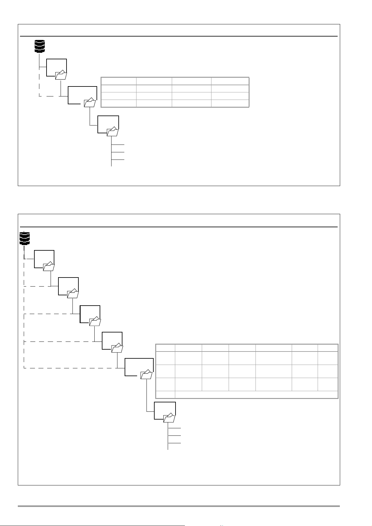
Test Structure – Hierarchy of Object Levels in the SECUTEST BASE(10)
Customer
ID
Designation
Street
Device
ZIP code
City
Database
ID
Designation
Measurement 1
Measurement 2
Measurement 3
Manual
sequence
* Test interval: additionally available for test instruments with database extension, feature KB01, “Z853R – SECUTEST DB+” or feature KD01, “Z853S – SECUTEST DB
COMFORT”
Customer MEM
1/4 2/4 3/4 4/4
ID Test interval * Comment Cost center *
Designation Type Serial number Department *
Location Manufacturer Protection category
Building
Floor
Room
ID
Designation
Street
ID
Designation
ID
Designation
Device
ZIP code
City
Database
Manual
ID
Designation
Measurement 1
Measurement 2
Measurement 3
Proper-
ID
Designation
ty
sequence
* Test interval: additionally available for test instruments with database extension, feature KB01, “Z853R – SECUTEST DB+” or feature KD01, “Z853S –
SECUTEST DB COMFORT”
** Only with SECUTEST PRO BT comfort or with database extension, feature KD01, “Z853S –
SECUTEST DB COMFORT”:
additional entry option for medical electric device (ME Device) and further parameters such as UDI and application parts
ME device **
UDI = unique device identification
1/6 2/6 3/6 4/6 5/6 6/6
ID Test interval * Comment No. of type B appl.
parts **
Cost center
Mains
conn. **
Designation Type Serial no. No. of type BF
appl. parts **
Department
Customer Manufacturer Protection
category
No. of type CF
appl. parts **
UDI **
Location Property
Building Floor Room
Location MEM
Figure 4 Database Structure
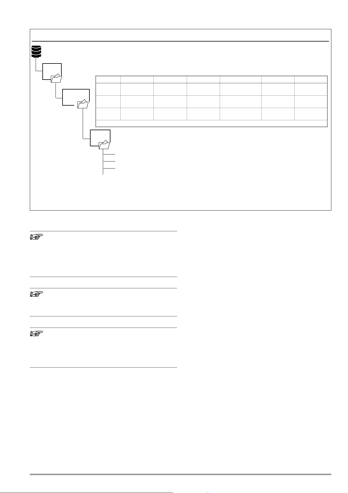
Test Structure – Hierarchy of Object Levels in the SECUTEST PRO and the SECULIFE ST BASE(25)
or in Devices with Database Extension, Feature KB01, “Z853R – SECUTEST DB+”
Figure 5 Database Structure as Location View in Test Instruments with Feature KB01, “Z853R – SECUTEST DB+”
16 GMC-I Messtechnik GmbH
Page 17
Test Structure, Customer View – Hierarchy of Object Levels in the SECUTEST PRO and the SECULIFE ST BASE(25)
Note
Note
Note
Customer
ID
Designation
Street
Device
ZIP code
City
Database
Manual
ID
Designation
Measurement 1
Measurement 2
Measurement 3
sequence
* Test interval: additionally available for test instruments with database extension, feature KB01, “Z853R – SECUTEST DB+” or feature KD01, “Z853S – SECUTEST DB
COMFORT”
** Only with SECUTEST PRO BT comfort or with database extension, feature KD01, “Z853S –
SECUTEST DB COMFORT”:
additional entry option for medical device (ME Device) and further parameters such as UDI and application parts
ME device **
UDI = unique device identification
1/6 2/6 3/6 4/6 5/6 6/6
ID Test interval * Comment No. of type B appl.
parts **
Cost center
Mains connection **
Designation Type Serial no. No. of type BF appl.
parts **
Department
Location Manufacturer Protection cate-
gory
No. of type CF appl.
parts **
UDI **
Customer
Customer
Customer MEM
or in Devices with Database Extension, Feature KB01, “Z853R – SECUTEST DB+”
Figure 6 Database Structure as Customer View in Test Instruments with Feature KB01, “Z853R – SECUTEST DB+”
Hierarchies and Data Migration
Database objects “Device” and “ME Device” must always be subordinate to a Customer. If so-called “legacy data” have been
imported into the test instrument which do not comply with this
rule (e.g. as a result of a firmware update or via the “Restore database” function), Customer objects are generated automatically.
The same applies to database objects “Room” and “Floor”, which
must always be subordinate to a Building. In this case, Building
objects are generated automatically if necessary.
Grayed Out Database Elements
The corresponding elements are grayed out in devices
without enabling for the following options: “Extended
database structure” Z835R (feature KB01 = property,
building, floor, room) and SECUTEST DB comfort Z853S
or feature KD01 (medical electric devices).
Mandatory Fields
Mandatory fields are marked in red in the entry fields at
the test instrument, as well as in Figure 5 and Figure 6.
Hierarchies
It’s imperative to adhere to the following hierarchies:
Room or Floor must always be subordinate to a Building.
Devices or ME Devices (medical electric devices) always be
allocated to a Customer.
5.2.4 Switching Between 2 Tree Structure Views (for SECUTEST PRO and SECULIFE ST BASE(25) or for devices with feature KB01, “Z853R – SECUTEST DB+”)
➭ The display can be switched back and forth between the lo-
cation and customer views by repeatedly pressing the MEM
key.
➭ The database view can be exited by pressing the ESC key.
GMC-I Messtechnik GmbH 17
Page 18
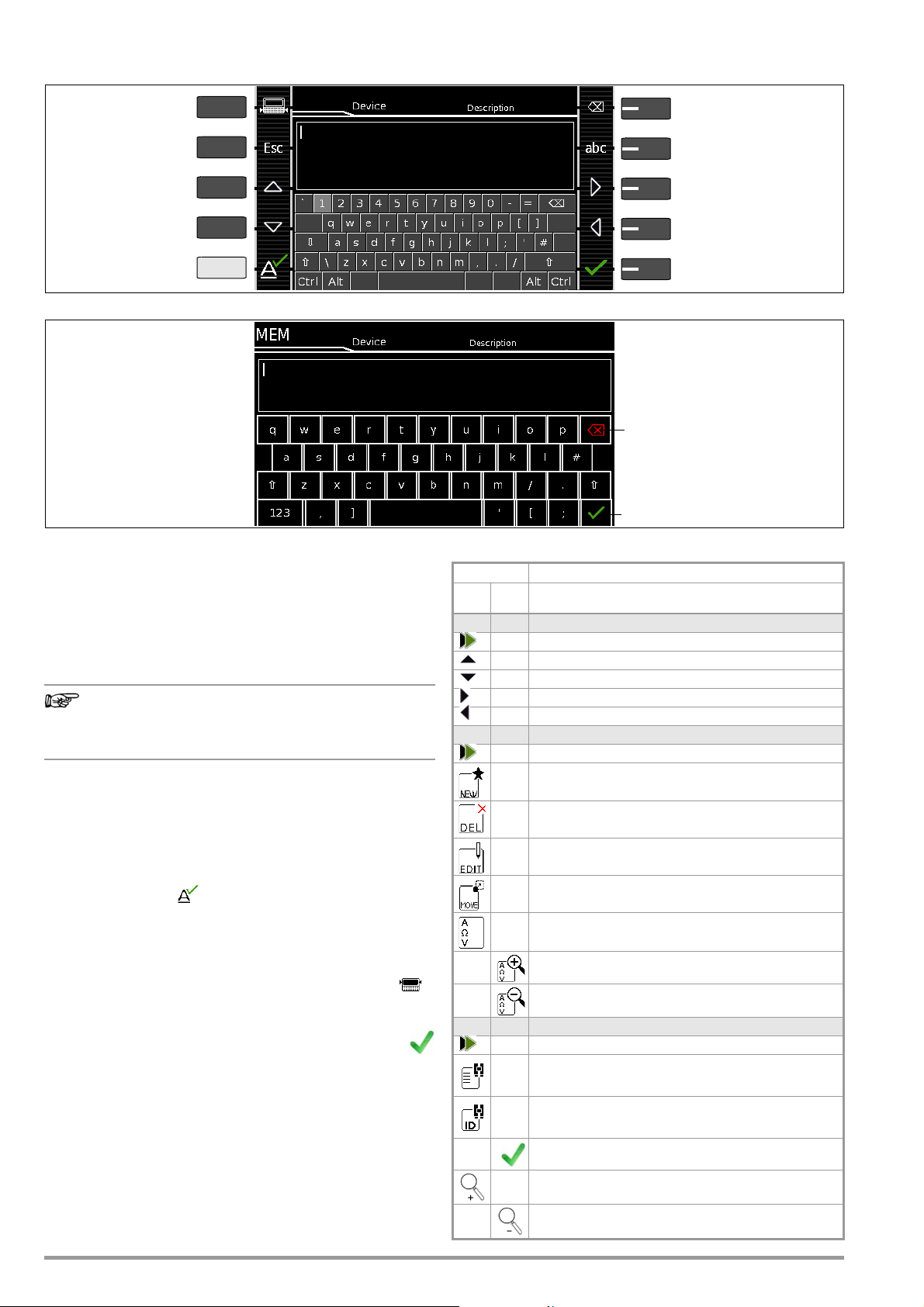
5.3 Data Entry
Note
Delete characters from right
Switch between upper/
Scroll left
Accept entry
lowercase, and symbols
Switch between
Scroll down
Transfer character at
Exit entry function
Scroll right
Display panel
Keypad
cursor position to display field
without saving
Scroll up
keys and display panel
PRINT
ESC
HELP
MEM
Accept entry *
Display Panel
Keypad
Delete characters from right *
* Also via assigned softkey
➭
Briefly pressing the shift key
once causes the next character to appear in uppercase.
➭
Pressing the shift key for a
longer period of time causes
all following characters to appear in uppercase.
➭
The cursor can be positioned
as desired by pressing the
display panel at the respective point in the existing text.
Overview of Keyboard Entries Via the Softkeys with the SECUTEST BASE(10)
Overview of Keyboard Entries via the Touchscreen Keyboard with the SECUTEST PRO (feature E01)
5.3.1 Keyboard Entries via Softkeys or External Keyboard
After selecting ID or any other object parameter, a keyboard is displayed which allows for the entry of alphanumeric characters via
the fixed function keys and the softkeys. Alternatively, entries can
also be made with the help of a USB keyboard or barcode scanner which is connected to the instrument.
The keyboard layout can be matched to the language in SETUP.
SETUP 2/3 > Culture > Keyboard Layout (for alphanumeric entries)
In order to use a USB keyboard at the SECUTEST..., the
“Keyboard Layout Settings” in Setup must coincide with
the connected keyboard.
Procedure (example: entering a designation):
1 Switch the keyboard to uppercase, lowercase or special char-
acters with the abc key (Abc, ABC, Symb).
2 Select the desired alphanumeric character or a line break with
the scroll keys (left, right, up and down). The selection cursor
can be accelerated by pressing and holding the respective
scroll key.
3 After pressing the key, the respective character appears
at the display panel.
4 Repeat steps 1 through 3 until the complete designation is
shown at the display panel.
5 The designation at the display panel can be changed subse-
quently by hiding the bottom keyboard by pressing the
key. The cursor position can then be changed in order to
delete individual characters.
6 The value appears at the display after pressing the
green checkmark.
5.3.2 Data Entry via Touchscreen Keyboard (only with SECUTEST PRO or test instrument with feature E01)
The touchscreen keyboard permits convenient entry of data and
comments, selection of parameters and direct parameter selection, and menu-driven operation is still possible via the softkeys as
an alternative.
18 GMC-I Messtechnik GmbH
Meaning of Symbols in the User Interface – Database Management
Symbol Meaning
Main
Sub-
Level
level
Memory menu, page 1 of 3
Change display to menu selection
Cursor UP: scroll up
Cursor DOWN: scroll down
Cursor RIGHT: open tree
Cursor LEFT: close tree
Memory menu, page 2 of 3
Change display to menu selection
Add a structure element
Delete selected structure element or measurement
Edit structure elements
(ID, designation, comment ...)
Move structure element
(feature KD01, “Z853S – SECUTEST DB COMFORT”)
When a measurement is selected: Display mea-
sured values
Display details from the measurement results list
Hide details from the measurement results list
Memory menu, page 3 of 3
Change display to menu selection
Search for ID, text or UDI > enter complete ID num-
ber (ID) or text (complete word)
Search for ID number: > Enter complete ID number
of a test object
Confirm search results
Display the structure designation
Hide the structure designation
Page 19
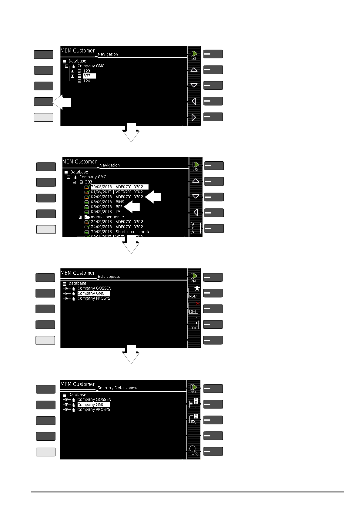
5.4 Creating a Test Structure in the Test Instrument, Navigating within the Structure and Displaying Measured Values
Scroll to next menu (page 2/3)
Object selection menu – page 1/3
PRINT
ESC
HELP
MEM
Select customers or devices
Select customers or devices
Select customers or devices
Scroll to next menu (page 3/3)
Object editing menu – page 2/3
Edit device/customer
Move object
Scroll to next menu (page 1/3)
Object search menu – page 3/3
Search by entering text
Search by entering IDs
Display designation and ID
of the selected device
MEM 1/3
MEM 2/3
MEM 3/3
Scroll to next menu (page 2/3)
Measurement selection menu – page 1/3
Selection of measurements
Selection of measurements
Jump back (one hierarchical level higher)
MEM 1/3
or close open branches
Jump back (one hierarchical level higher)
or close open branches
1
2
Display measured values for a selected test
1: Test sequence per standard (symbol: orange)
2: Single measurement (symbol: green)
Note: See page 17 concerning grayed out database elements.
Either “Delete selected customer, (ME) device or measurement” or “Delete selected object with all subordinate
objects/measurements”
Add new (ME) device to the selected customer or
clone current element (as of firmware 3.0)
PRINT
ESC
HELP
MEM
PRINT
ESC
HELP
MEM
PRINT
ESC
HELP
MEM
Overview of the Meanings of the Symbols for Creating Objects – Navigation within Test Structures
Figure 7 Overview of Navigation, Object Editing and Object Search in the Database
GMC-I Messtechnik GmbH 19
Page 20
5.4.1 General Procedure for Creating Test Structures
Note
After selection with the MEM key, all setting options for the creation of a tree structure are made available on three menu pages
(1/3, 2/3 and 3/3). The tree structure consists of structure elements, referred to below as objects.
Results of measurements/tests can only be saved under structure
elements types “Device” or “ME device” (medical electric device),
which are also referred to as “test objects” in the following.
Select the position at which a new object will be added.
➭ Use the or key in order to select the desired structure
elements.
➭ If a sublevel exists, you can switch to it by pressing the key,
or you can open a branch.
➭ The open branch is then closed, or you can switch to the next
higher hierarchical level, by pressing the key.
Creating a New Object
➭ Scroll to the second menu page (MEM 2/3) with the help of
the key.
➭ After pressing NEW, a new object can be created. Depending
on the current position within the hierarchy, the respectively
available object types are suggested. Depending on the object type, you’ll have to enter at least an ID number via the
keyboard. If any of the mandatory entries (identified in red)
have not been completed, an error message appears.
➭ Then press the green checkmark in order to accept the
entered values. The display jumps back up to the higher
hierarchical level.
➭ Now select the position with the scroll keys to which the ob-
ject will be moved.
➭ The display is automatically returned to the initial window after
confirming with the green checkmark.
Editing an Object –
Changing the Description or ID Number of a Previously Created
Object
➭ Scroll to the first menu page (MEM 1/3) with the help of the
key.
➭ Select the structure element whose designation will be
changed.
➭ Scroll to the second menu page (MEM 2/3) with the help of
the key.
➭ Press the EDIT icon.
➭ Select the parameter whose description will be changed.
The keyboard appears automatically.
➭ Change the displayed designation and acknowledge your en-
try.
Quick Command: Edit Object
and
feature KD01, “Z853S – SECUTEST DB COMFORT”)
(optional feature E01 (touchscreen)
Move an Object (feature KD01, “Z853S – SECUTEST DB COMFORT”)
➭ Scroll to the first menu page (MEM 1/3) with the help of the
key.
➭ Select the object to be moved (together with sub-objects) with
the scroll keys.
➭ Scroll to the second menu page (MEM 2/3) with the help of
the key.
➭ Press the MOVE icon.
➭ Using the scroll keys, select the position to which the object is
to be moved and confirm by pressing the green checkmark.
Quick Command: Move Object (optional feature E01 (touchscreen)
and feature KD01, “Z853S – SECUTEST DB COMFORT”)
➭ Press and hold the object to be moved in the tree view in the
initial window of a test sequence until the activity bar starts to
blink.
➭ Press and hold a point in the detail view field in the initial win-
dow of a test sequence until the activity bar starts to blink.
➭ Upon releasing finger pressure, the “Edit” menu for a device/
ME device (medical electric device) opens automatically.
➭ After entering or changing the data, the display is automati-
cally returned to the initial window upon confirming with the
green checkmark.
Depending on whether or not finger pressure is applied
for a longer period of time in the customer or location
tree, the device can be “moved” to another customer or
“moved” between locations.
➭ Upon releasing finger pressure, the display is automatically
switched to the database view (MEM), from where you can
proceed to the “Move” menu.
20 GMC-I Messtechnik GmbH
Page 21
5.4.2 Searching for Structure Elements
Note
Note
➭ Scroll to the first menu page (MEM 1/3) with the help of the
key.
➭ Scroll to the third menu page (MEM 3/3) with the help of the
key.
➭ Press the text symbol in order to search for text.
➭ Press the ID symbol in order to search for an ID number.
There are three ways to enter search terms:
– Via the softkeys
– Via a connected USB keyboard
– Via a barcode or an RFID scanner
Distinction is made between upper and lowercase as of
firmware version 2.1.1.
The keyboard entry function is opened automatically in either
case.
➭ The search is started after the entered search term has been
acknowledged.
When searching for IDs, differentiation is made between
uppercase and lowercase (as of firmware 2.1.1).
When searching for text, elements are found regardless
of whether they are written in upper or lowercase.
The found object is displayed inversely.
➭ If several objects are found which match the search string,
you can toggle with the scroll keys between the different
search results.
➭ The designation and ID number can be shown or hidden by
pressing the magnifying glass symbol.
5.4.3 Display Measured Values from Saved Tests
➭ Switch to the database view by pressing the MEM key.
➭
Scroll to the first menu page
of the key.
➭ Either select the desired object (ID number) with the scroll
keys or search for it as described in Section 5.4.2.
➭ Then mark the desired test with the cursor, depending on
whether single measurements or test sequences are involved:
Single measurements: date / measuring function(7/17/14 / RINS)
Test sequence: date / test standard (7/17/14 / VDE...)
➭ In order to view the single measurements of a test se-
quence after testing, press the symbol for executed
measurements. The measurements appear in a list.
➭ Select the desired measurement with the scroll keys.
➭
The associated measuring parameters can be shown or
hidden using the keys shown at the right.
➭ The measured value view is exited by pressing the
green checkmark.
(Navigation) (MEM 1/3) with the help
5.4.4 Clearing the Database
The database in the test instrument can be cleared in two different
ways:
• SETUP switch setting, page 1/3 > Database > Delete
• Press the MEM key > scroll up with the scroll key until the
database is selected > press the DEL softkey.
GMC-I Messtechnik GmbH 21
Page 22
6 Connecting the Device Under Test
Note
Note
➭ Connect the DUT in accordance with the schematic diagrams
included in the online help function.
Connection of the DUT to the test instrument depends on:
• The type of DUT:
For direct connection to the test socket (TS)
Devices with single-phase connection
and extension cords via the EL1 adapter
(in which case the EL1 is connected to probe sockets P1)
For permanent connection (to the mains)
by contacting the housing with the probe
(for the measurement of protective conductor resistance or
with the direct measuring method for the touch current
measurement)
Measurement of protective conductor current
(only possible with feature I01)
For connection via adapter
– With single-phase extension cords via the EL1 adapter
(in which case the EL1 is connected to probe sockets P1)
– With single and 3-phase extension cords
the test socket
– Devices with 5-pole, 16 A CEE plug
via the AT16-DI differential current adapter to the test socket
– Devices with 5-pole, 32 A CEE plug
via the AT32-DI differential current adapter to the test socket
• DUT protection category (PC I, PC II or PC III) or any combinations of protection categories
The DUT must be switched on for all tests. Switches,
relays, temperature regulators etc. must all be taken into
consideration.
As a default setting, the program sequence assumes that the plug
from the DUT has been connected to the test socket.
with a current clamp
via the
VL2E adapter to
Specifying an Alternative Test Frequency
Selectable frequency setpoint value for synthetic test voltage for
all leakage current measurements of measurement type “Alternative”, affecting the following measurements and/or rotary selector
switch positions:
– Single measurements (rotary switch level: green)
– Measurements included in predefined default test sequences
– Measurements included in user-defined test sequences (only with
database extension, feature KB01, “Z853R – SECUTEST DB+”)
The Alternative Test Frequency parameter can be set in Setup:
Setup 1/3 > All Measurements > Alternative Test Frequency
6.3 Manually Specifying the Connection Type for Single Measurements
In the case of single measurements the test instrument is unable
to detect the respective connection type (e.g. test socket or permanent connection (voltage measuring inputs)). The connection type
must be specified manually.
➭ Select parameter settings.
➭ After selecting the measurement type parameter, a list of possi-
ble connection types is displayed.
➭ Select a connection type.
6.1 Residual Current Monitoring
For your safety, the test instrument is equipped with continuous
residual current monitoring. If residual current exceeds a specified
limit value, all measuring processes are stopped, and if line voltage is fed through the test socket it’s disconnected. This limit
value can be set to one of two levels in the SETUP switch position:
Setup 1/3 > All Measurements > Residual Current Protection >
10 mA
/30 mA
6.2 Reference Voltage L-PE and Alternative Test Sequence
Specifying Reference Voltage L-PE
Reference (line) voltage is the voltage to which the measured values for leakage current have been standardized.
It’s used in the case of leakage current for mathematical adaptation of measured current values to the specified voltage.
Measurements with line voltage at the test socket: The setting value
has no influence on the voltage with which the test object is supplied via the test socket of the SECUTEST.
Leakage current measurements with “Alternative” method: The setpoint value of the synthetic test voltage is derived from the value
specified here.
The displayed measured values for leakage current are
standardized to an adjustable reference value (typically
230 V) in order to permit reproducible measurement of
leakage current even with fluctuating mains supply voltage
Once a connection type has been selected, it remains active for all
following tests until it’s changed once again.
6.4 Manually Selecting a Connection Type / Protection Category for Automatic Test Sequences
If the test instrument is unable to detect the respective connection
type or protection category, the suggested connection type must
be examined and the connection type or protection category
must be specified manually if necessary.
➭ Press the Sel key shown at the right in order to display
the Classific. parameters.
➭ After selecting the protection category or connection type
parameter, a list of possible settings is displayed.
➭ Select the respective parameter.
➭ Acknowledge the Class. Param. (classification parameters)
once again.
The connection type appears at the middle of the header.
The symbol for the respective protection category appears to
the right of the connection type.
Once a connection type
selected,
once again.
it remains active for all following tests until it’s changed
or a protection category has been
Reference voltage can be adjusted in Setup:
Setup 1/3 > All Measurements > Ref. Voltage L-PE
22 GMC-I Messtechnik GmbH
Page 23
6.5 Special Conditions
Note
Attention!
!
Attention!
!
Attention!
!
Protection Category II Devices with Protection Category I Mains Plugs
If the device under test is equipped with a protection category I plug although it complies with protection category
II, protection category I is recognized by the test instrument. If this is the case, switch the protection category
parameter from I to II.
Testing Several Protective Conductor Connections with the Function for “Automatic Detection of Measuring Point Changes”
During protective conductor measurement, the test instrument recognizes whether or not test probe P1 is in contact with the protective
conductor, which is indicated by means of two different acoustic signals. This function can be adjusted in the
Auto Measurements”
“
submenu via the “
SETUP
switch position in the
Auto Measuring Point
” parameter.
Protective Conductor and Insulation Resistance Measurements for
Permanently Installed Devices Under Test
Deactivate the electrical system which supplies power to
the device under test before connecting the test instrument!
➭ Remove the mains fuses from the device under test and dis-
connect neutral conductor N inside the device under test.
Touch Current Measurement (absence of voltage)
Make sure that the contacted parts are not grounded.
6.6 2nd Test Probe (only SECUTEST PRO or feature H01)
If the device under test is not equipped with a country-specific
mains plug which fits into the test socket at the SECUTEST, or if a
permanently installed DUT is involved, the second test probe, in
combination with the first test probe, permits 2-pole measurement (dual-lead-measurement) of RPE, RINS and equivalent leakage current.
Measurements with test probe 1 to test probe 2 (P1 – P2) are electrically isolated from the mains. There’s no voltage at the test socket.
Please note that during insulation measurement the
maximum test voltage of 500 V may be applied between
the probes.
6.7 Connection Prompts
If a single measurement (green rotary switch positions) or a specific (integrated) automated test sequence (orange rotary switch
positions) is started, checking is conducted to determine whether
or not all of the probes and measurement cables required to this
end are connected (depending on the configuration level of your
SECUTEST...). If this is not the case, you’re prompted to connect
probes, measurement cables or the test adapter to the SECUT-
EST....
Checking is only conducted to determine whether or not the corresponding sockets are occupied – make sure that suitable
accessories have been connected for the selected measurement/
connection type. A list of possible DUT connections depending
on type of measurement is included in section 11.2.
6.8 Connection Tests Conducted by the Test Instrument
The following measurements are performed automatically when
the DUT is connected to the test instrument.
• Detection of Probes / Measurement Cables
During individual measurements / automated test sequences,
checking is conducted to determine whether or not the measuring sockets required for the measurement/sequence are
occupied.
•
DUT connection detection
With the rotary switch in the AUTO/A1-A8 position, the “Test
(only with country-specific variant *)
Socket” connection type is selected automatically (if correspondingly configured), if a mains plug is detected in the test
socket.
• Protection category detection
(only with country specific variant *):
With the rotary switch in the AUTO/A1-A8 position, protection
category I or II is selected automatically (if correspondingly
configured), depending on the detected type of mains plug.
• Short-circuit test
Before switching mains voltage to the device under test: test
for short-circuiting between L and N or L/N and PE. If applicable additionally as “inspection test step” in automated test
sequences.
•
On test
(test whether the DUT is switched on or off)
Automatic Recognition of States
when Connecting DUTs and Probes
Control Function Condition
Short-circuit testL–N Short-circuit / DUT starting current R ≤ 2.5 Ω
Open-circuit voltage
Short-circuit testLN–PE short-circuit R ≤ 2 kΩ
Open-circuit voltage
On test On (DUT passive) R < 250 kΩ
Open-circuit voltage
Probe test No probe R > 2 MΩ
Protection class detection
Safety shutdown
Triggered at following residual current value (selectable)
Triggered at following probe current values
Connection test (only with country specific variant
Checks whether the DUT is connected to the test socket.
Insulation test
PE mains – PE socket: Open-circuit voltage
2mA
Overcurrent protection
Shutdown in the event of a continuous flow of current via the test socket at:
Our
SECUTEST BASE(10)/PRO
struments permit active testing of devices with nominal current (load
current) of up to 16 A.
The test socket on the respective test instrument is equipped with 16 A
fuses to this end and the switching capacity of the internal relays is also
16 A. Starting current of up to 30 A is permissible.
In the case of test objects for which a starting current of greater than
30 A can be expected, we urgently recommend the use of a test
adapter for larger starting currents, for example test adapters from the
AT3 series .
1
Applies to
2
Applies as of version 1.7.0, previous condition: ≤ 1.5 Ω respectively > 1.5 Ω
3
50 V DC as of version 2.1.1
U0 4.3 V, short-circuit current IK < 250 mA
U0 230 V AC, short-circuit current IK < 1.5 mA
U0 230 V AC, short-circuit current IK < 1.5 mA
(only with country specific variant 1)
Protective conductor found: PC I R < 1 Ω
1
During leakage current measurement > 10 mA
During protective conductor resistance measurement > 250 mA
DUT set up in a well-insulated fashion R ≥ 500 kΩ
DUT set up in a poorly insulated fashion R < 500 kΩ
and
SECULIFE ST BASE(25)
M7050
with feature B00 and B09
* Safety Shutdown
As of 10 mA of differential current (can also be set to
30 mA), automatic shutdown ensues within 500 ms. This
automatic shutdown does not take place during leakage
current measurement with clamp meter or adapter.
No short-circuit (AC test) R > 2.5 Ω
No short-circuit (AC test) R > 2 kΩ
Off (DUT active) R > 300 kΩ
Probe detected R < 500 kΩ
No protective conductor: PC II R > 10 Ω
1
DUT power cable found R < 1 Ω
No DUT power cable R > 10 Ω
U0 500 V DC3, IK <
test in-
2
2
> 10 mA / > 30 mA
I > 16.5 A
GMC-I Messtechnik GmbH 23
Page 24
7 Notes on Saving Single Measurements and Test
1
2
Sequences
At the end of each test, test results can be saved under an ID
number which is unequivocally assigned to the respective test
object (= device or ME device (medical electric device)).
Depending on the initial situation, i.e. whether or not a test structure or database is already available or an ID has already been
entered, the following different procedures are used for saving:
Variant 1 – preselection of an existing ID
You’ve already set up a test structure in the test instrument or
uploaded one with the help of report generating software.
Open the database view before starting the measurement by
pressing the MEM key. Then select the test object or its ID within
the test structure by pressing the respective scroll key. Exit the
database view (MEM navigation) by pressing ESC and start the
measurement. Press the “Save as” key at the end of the measurement. The display is switched to the SAVE view. The ID
appears with a green or orange background. Press the Save key
once again in order to complete the procedure.
Variant 2 – entry of a previously saved ID at the end of the test
You’ve already set up a test structure in the test instrument or
uploaded one with the help of report generating software.
You perform the measurement without first opening the database.
No test object was previously selected in the database. Press the
“Save as” key at the end of the measurement. The following
message appears: “No DUT selected!” Press the ID key. The softkey keyboard appears.
If you enter an ID here which is already in the database, the database view appears (MEM navigation) automatically, and the test
object’s ID is displayed inversely. Acknowledge the entry by
pressing the key. The display is switched to the SAVE view. The
ID appears with a green or orange background. Press the Save
key once again in order to complete the procedure.
Variant 3 – entry of a new ID at the end of the test
You haven’t yet set up a test structure in the test instrument, or
the ID is not included in the existing structure.
Press the “Save as” key at the end of the measurement. The
following message appears: “No test object selected!” Press the
ID key in order to enter the test object’s ID. The softkey keyboard
appears.
If you enter an ID here which is not yet included in the database, a
prompt appears asking you if you want to enter a new test object.
– Selection : If you press , the display is switched to the SAVE
view. The ID appears with a green or orange background. Press
the Save key once again in order to complete the procedure.
– Selection : If you press , the display is switched to the
database view (MEM navigation). You can go to the next page
(Edit Objects 2/3) by pressing , and then enter a new test
object. Press to this end. All possible object types are displayed. Press Device. The newly entered ID appears in red to
the right of the ID parameter. Acknowledge the entry by pressing the key. The display is switched to the database view
(MEM navigation). The newly entered test object is displayed
inversely in the structure. Press ESC
view. The ID appears with a green background. Press the Save
key once again in order to complete the procedure.
– ESC: If you don’t want to save any measured values, press ESC
twice in order to go to the measuring view. If you press ESC
again, a prompt appears asking whether or not you want to
delete the measuring points in order to continue with the measurement without saving.
in order to return to the SAVE
7.1 QuickEdit Function – QEDIT (feature KD01, “Z853S – SECUTEST DB COMFORT”)
QuickEdit is available whenever you search for a test object ID
and the ID doesn’t already exist in the database.
The following search options are available:
– Via the ID softkey in the test sequence (AutoTest) or in the
save menu of the manual test
– ID search via ID softkey on page 3 of 3 of database manage-
ment MEM
– Read-in of a test object ID via the barcode or RFID scanner
If the searched for ID is not found, the following question appears.
When creating a new object you can first of all choose between a
(standard) test object ( icon) or a medical test object – “new
ME device” in (staff of Aesculapius icon ) by pressing the (1)
key.
If you select QEDIT (Quick Edit function), key (2) (shown against a
green background and not crossed out), you proceed directly to
the memory management entry window by confirming with , in
order to create a new test object and enter further properties.
After confirming with , the location of the ID in the database is
displayed. Measurement results are saved to memory after pressing the Save key once again.
24 GMC-I Messtechnik GmbH
Page 25
8 Single Measurements
Measurement Status – Progress Bar
Measurement standstill (static line)
Measurement in progress (space is gradually filled in, pulsating)
PRINT
ESC
HELP
MEM
Select parameters
Measuring View, Single Measurements
Select measurement/connection type
Adjust test current
Reset offset to 0 Ω
Offset
Test cur re n t
Measurement/connection type
q
Measurement
– Start
– Stop
Probes/sensors: green = connected to test instrument
Scroll through parameter pages
Select measuring parameter directly
Select measuring parameter directly
Select measuring parameter directly
Accept changes
Measuring Parameters Display, Single Measurements
and jump back to measuring view
Current/maximum number of parameter pages
ESC: Discard changes
and jump back to measuring view
Selected
parameter value
Selectable
parameter
Delete character
Accept character at cursor
Scroll left
to the left of the cursor in the display
Accept entry
Scroll up
Scroll down
and exit keyboard
Discard entry
and exit keyboard
position
Scroll right
Display keyboard > select/acknowledge digits
/ hide keyboard > edit display value
Numeric Entry (for parameters UISO(set), Offset ...) via Softkeys with the SECUTEST BASE(10)
Delete character to the left of the cursor
in the display *
Accept entry
and exit keyboard *
Numeric Entry (for parameters UISO(set), Offset ...) via Touchscreen Keyboard with the SECUTEST PRO (feature E01)
* Also via assigned softkey
PRINT
ESC
HELP
MEM
PRINT
ESC
HELP
MEM
Monentarily measured value
8.1 General
• The desired measurement is selected with the help of the green
pointer on the rotary switch and the green semicircle.
• The respective measurement is configured with the help of
the softkeys. The parameter settings can be accessed by
pressing the softkey with the symbol shown at the right.
•The measurement type parameter displayed in each case
in the footer can be changed directly using the key
shown at the right without having to exit the measuring
view.
• The selection of
can be changed directly using the key shown at the right
without having to exit the measuring view.
• No limit values can be specified for single measurements, and
thus there’s no evaluation.
polarity
for line voltage at the test socket
• Checking is performed before each measurement in order to assure a
trouble-free sequence, and to prevent any damage to the DUT.
• Single measurements can be saved to memory. The assignment of an ID number is possible to this end.
• Single measurements can be combined into measurement series.
• Mains power can be connected to the
device under test
with the
desired polarity by making a pre-selection in the parameter settings.
Figure 8 Configuring Single Measurements (parameters entry and display)
GMC-I Messtechnik GmbH 25
Page 26
8.2 Meaning of Symbols in the User Interface
Note
1
1
0
1
3
3
3
Sym-
Softkey Variants, Single Measurements
bol
Set parameters
Accept changed parameters, acknowledge memory location
Acknowledge messages during tests/measurements
and resume test sequence
Abort measurement
Direct selection key for selecting the measurement type
Currently selected polarity: “L-N”
Press key to change polarity
Currently selected polarity: “N-L”
Press key to change polarity
Ip
Direct selection key for selecting test current for protective
conductor measurement
U+
Direct selection key for changing voltage in 10 V steps for
U–
insulation measurement
Start evaluation – record measured value. Each time this
softkey is pressed, an additional measured value is saved
and the number is increased by one.
The ID number to which the measurement(s) will be stored
can be entered here.
Valid measured values have been obtained for a measurement. This measurement can be saved.
Save measurement data as (with display of directory path
/ ID or new entry of an ID other than the preselected one)
Transmit measurement data to a PC, e.g. in order to save
them to IZYTRONIQ report generating software (push-print
function) –
refer to IZYTRONIQ online help for a description
Display measured values from performed measurements
Magnifying glass icon: Magnifying glass icon: show (+) or
hide (–) details regarding database objects or selected
measurements
8.3 Displaying the Last Measured Values
1 Start the measurement by pressing the START/STOP but-
ton.
The symbol shown at the right appears and indicates
how many measurements have already been performed.
2 Stop the measurement by pressing the START/STOP
key, unless a specified measuring time has been stipulated.
The save symbol (floppy disk with a number 1)
appears and indicates that one valid measured value has
been recorded, which can now be saved.
3 Press the save symbol (floppy disk).
“No DUT selected!” appears.
4 In order to view the last measured values, press the
symbol for executed measurements after testing. The
last measured values are displayed.
5 The desired measurement can be selected with the
scroll keys.
6 The associated measuring parameters can be shown or
hidden using the keys shown at the right.
7 The measured value view is exited by pressing the
green checkmark in order to subsequently save the measured
values (as described in Section 8.4) or to return to the initial
view by pressing the ESC key.
8.4 Measurement Series and Storage
Single measurements can be combined into measurement series.
The measured values can be saved by pressing the save key, or
measurement series can be generated. These can be saved to a
test object (ID number) which has already been set up in the database (see Section 5.4.1). The appearance of the save key
changes depending on meaning.
Measuring Sequence with Pre-Selection of the Test Object
1 Activate the database view (MEM navigation) by pressing the
MEM key.
2 Select the test object or its ID number for the following
measurements with the scroll keys.
3 Return to the measuring view by pressing the ESC key or
the START/STOP key.
4 Start the test with the START/STOP key.
The symbol shown at the right appears and the zero
indicates that no measurements have yet been
recorded or saved to buffer memory.
5 Each time the key at the right is pressed, the respec-
tively current measured value is saved to buffer memory and the number shown in the symbol is increased.
In this way, you always know how many measurements have
already been recorded.
6 Stop the measurement by pressing the START/STOP
key, unless a specified measuring time has been stipulated.
The Save as symbol appears (floppy disk icon with the
number of measured values saved to buffer memory).
7 If you press the save symbol now (floppy disk), the dis-
play is switched to the test object in the database view for
checking.
8 After pressing the save symbol once again, acknowledgement
of successful storage appears. At the same time, the display
is switched to the measuring view.
Measuring Sequence with Subsequent Entry of the Test Object
1 Start the measurement by pressing the START/STOP but-
ton.
The symbol shown at the right appears and indicates
how many measurements have already been performed.
2 Stop the measurement by pressing the START/STOP
key, unless a specified measuring time has been stipulated.
The save symbol (floppy disk with a number 1)
appears and indicates that one valid measured value has
been recorded, which can now be saved.
3 Press the save symbol (floppy disk).
4 You’re informed that you haven’t selected a test object
in the database.
5 There are two ways to subsequently select your test
object using an ID number which has already been set
up in the database:
– Select the ID number with a barcode scanner
or
– Enter an ID number by pressing the ID key.
6 The cursor jumps to the location of the test object with the
selected ID number. You only need to acknowledge this posi-
tion by pressing the green checkmark.
7 Press the save symbol (floppy disk).
A message appears indicating that the data have been suc-
cessfully saved and the display is switched to the measuring
view.
If the entered number cannot be found in the database
(because it hasn’t been set up), it can be entered immediately by pressing Yes when the prompt appears.
However, the storage location cannot be selected in this
case. The measurement is saved to the most recently
selected hierarchy.
26 GMC-I Messtechnik GmbH
Page 27
Note
Measurements and measurement series can only be
Note
R
PE
saved after measurement has been completed. Measured values can only be added to intermediate buffer
memory during a measurement. Customer, location and
other entries cannot be changed in the memory menu.
These have to be selected directly in the database and
entered or changed.
Please observe the following before storing tests or measurements to the test instrument:
If applicable, the date of recalibration is printed on test
reports, or transmitted to a PC during when exporting
test data. For this reason we recommend checking the
recalibration date saved in the test instrument before
starting work with your new test instrument (see
page 12).
8.5 Measuring Protective Conductor Resistance – RPE
Protection Category I Devices
– Measurement type PE(TS) - P1 (passive)
– DUT mains plug to test socket
– Test probe P1 to P1 terminals
Schematic Diagram
Protective conductor resistance is measured between the earthing contacts at the mains plug and the earthing contact connected to the housing by contacting the housing with test probe
P1.
Wiring Diagram
Single measurements, rotary switch level: green
Measurement Type,
with Mains
to Test
Socket
Switch
Position
Active:
PE(TS) - P1
R
PE
1
10/25 A-RPE measurements are only possible with line voltages of 115/230 V and
line frequencies of 50/60 Hz.
2
Connection of 2nd test probe for two-pole measurement with SECUTEST PRO/
SECULIFE ST BASE(25) (or instrument with feature H01)
3
Can only be selected if the IP(set) parameter has been set to 10 A~
only with SECUTEST PRO/SECULIFE ST BASE (or instrument with feature G01)
4
Can only be selected with SECUTEST BASE or if the IP(set) parameter has been set
to 200 mA.
Measurement Type,
without
Mains
Measuring Functions
R
PE
Ip Test current
Protective conductor
resistance
to Test
Socket
200 mA
Passive:
PE(TS) - P1
4
PE(mains) - P1 ••
PE(mains) - P1
3
clamp
P1 - P2 2 •••
•••
•
10 A
1
•
25 A
1
Application, Definition, Measuring Method
Protective conductor resistance is the sum of the following resistances:
• Connector cable or device connector cable resistance
• Contact resistance at plug and terminal connections
• Extension cord resistance if applicable
Measurement of RPE at Single-Phase Extension Cords with EL1
– Measurement type PE(TS) - P1 (passive)
– Extension cord plug to test socket
– EL1 to P1 terminals
Schematic Diagram
Wiring Diagram
GMC-I Messtechnik GmbH 27
Page 28

Protection Category I Devices
Special Case: Line Voltage at Test Socket (for testing PRCDs)
– Measurement type PE(TS) - P1 (active)
– DUT mains plug to test socket
– Test probe P1 to P1 terminals
Schematic Diagram
Protective conductor resistance is measured between the earthing contacts at the mains plug and the earthing contact connected to the housing by contacting the housing with test probe
P1.
Wiring Diagram
Measurement via current clamp sensor
at permanently installed DUT
– Measurement type PE(mains) - P1 clamp
– Test probe P1 to P1 terminals
– Clamp to COM-V (only with SECUTEST PRO or feature I01
with
optional current clamp sensor)
Schematic Diagram
Measurement of test current by closing the current clamp sensor
around mains PE and contacting the housing with test probe P1
for permanently installed protection category I devices under test
Wiring Diagram
Protection Category I Devices
Special Case: Permanently Installed DUTs
– Measurement type PE(mains) - P1
– Test probe P1 to P1 terminals
Schematic Diagram
In the case of permanently installed DUTs, protective conductor resis-
tance is measured between the mains power earthing contact
and the earthing contact connected to the housing by contacting
the housing with test probe P1.
Wiring Diagram
Set Measuring Range at Current Clamp Sensor and Parameter at the
SECUTEST PRO or SECULIFE ST BASE
This measurement type can only be selected if test current is set
to 10 A AC.
SECUTEST PRO Clamp SECUTEST PRO
Transformation Ratio
Parameter
1 mV : 1 mA
* Only with WZ12C
Transformation
Ratio
(switch *)
1 mV : 1 mA 1 mA ... 15 A 0 mA ... 300 A
WZ12C
Measuring
Range
Display Range
with Clamp
2-Pole Measurement at Permanently Installed DUTs
(only with SECUTEST PRO or feature H01)
– Measurement type P1 - P2
– Test probe P1 to P1 terminals
– Test probe P2 to P2 terminals
Schematic Diagram
PE at the mains connection is contacted with the second test
probe instead of via the test instrument’s mains plug.
28 GMC-I Messtechnik GmbH
Page 29

Wiring Diagram
Attention!
!
Attention!
!
Resistance is measured:
• Between each exposed conductive part of the housing and the
earthing contacts at the mains and the device plug (if a
removable mains connector cable is used), or the protective
conductor terminal for permanently installed devices.
• As 4-pole measurement
• Between the earthing contacts at the mains plug and the
earthing contacts at the device plug for device connector cables
• Between the earthing contacts at the mains plug and the
earthing contacts at the coupling socket for extension cords
Setting Measuring Parameters for RPE
Measuring Parameter
Measurement Type
(passive:) PE(TS)
– P1
Active: PE(TS) –
1
P1
PE(mains) – P1
Permanently connected DUTs
P1 – P2
2
Clamp
IP(set)
+200 mA DC Test current: positive direct current
-200 mA DC Test current: negative direct current
±200 mA (DC) Test current: direct current whose polarity is reversed every 2 sec-
200 mA (AC) Test current: alternating current, adjustable frequency f, see below
10 A (AC)
25 A (AC)
f – only at 200 mA (AC)
50 ... 200 Hz Test frequency (adjustable in steps: 50, 60, 110, 150, 200 Hz)
Offset
> 0 ... < 5 Ω Zero balancing for a selected reference point.
Meaning
Testing is conducted between the
two protective conductor terminals:
at the test socket and test probe
P1.
Same as PE(TS) – P1, but with
line voltage to the test socket,
200 mA AC flows immediately.
A ramp-like, slowly rising DC test
current flows (PRCD triggering is
avoided) at +200 mA DC, 200 mA DC and ±200 mA DC.
Testing is conducted between the
ground terminal at the mains and
test probe P1.
SECUTEST PRO/SECULIFE ST BASE
(feature H01):
2-pole measurement between
test probes 1 and 2 (see section
6.6)
SECUTEST PRO/SECULIFE ST BASE
(features G01 and I01):
Test current measurement with
current clamp sensor
onds
10 A test current:
25 A test current:
SECUTEST BASE10 or PRO
SECULIFE ST BASE25
Suitable for
DUT Connection via
Test socket, EL1 with DUT at test
socket, VL2E, AT3 adapter (AT3IIIE, AT3-IIS, AT3-IIS32),
AT16DI/AT32DI
Test socket (for PRCDs)
Permanent connection
Permanent connection
Permanent connection
only (feature G01)
only (feature G02)
Entering and Deleting Offset Values
The test instrument determines protective conductor resistance
by means of a 4-pole measurement. If measurement cables or
extension cords are used whose ohmic resistance should be
automatically subtracted from the measurement results, there are
two ways to save the respective offset value in the RPE switch
position:
• Entry via the numeric keypad
• Acceptance of the momentary measured value by pressing the
OFFSET
softkey
SET
Proceed as follows in order to accept the measured value:
➭
Start the measurement and wait until the measured value settles in.
➭ Press the
SET OFFSET
key. The value is transferred to the offset
field.
The entered or accepted offset value is permanently stored and is
subtracted from all protective conductor resistance values measured in the future. This applies to single measurements as well
as to measurements conducted in the AUTO switch positions.
The symbol is displayed in the header in all switch positions
until the offset value is deleted by pressing the CLEAR OFFSET softkey (R
switch position).
PE
Protective Conductor Current Measurement with 25 A AC
In accordance with IEC 60601, at least 25 A must be achieved
with a load of 0.1 Ω and a maximum voltage of 0.6 V.
Continuous protective conductor resistance measurement with a
test current of 25 A is not possible due to contact resistance at
the jacks.
If the test instrument is operated at room temperature, an uninterrupted test duration of at least 15 seconds is possible. Under other
conditions, maximum test duration may be shorter and/or the
measurement may be prematurely terminated.
Suitable measurement cables with a minimum cable
cross-section of 2.5 mm must be used when measuring
protective conductor resistances with a “25 A AC” test
current.
Included with the SECULIFE ST BASE25: suitable test probe
with green strain relief sleeve.
For subsequent orders, we recommend the SK2-25A
test probe (Z746C).
Under certain circumstances, the required standard values might not be complied with if unsuitable accessories
are used.
Measurement duration with a 25 A test current is limited
(see technical data).
An error message is generated if measurement duration
is exceeded which results in a temperature increase at
the test instrument.
Clamp factor – only for clamp measurement type
1 mV : 1 mA Transformation ratio of the WZ12C current clamp sensor.
1
Measurement cannot be performed with 10/25 A AC for this measurement type.
2
SECUTEST PRO /SECULIFE ST BASE (feature G01): This type of measurement can only
be selected if a test current of 10 A AC has been chosen.
GMC-I Messtechnik GmbH 29
For setting the current clamp factor at the WZ12C clamp and the
SECUTEST PRO (see table above).
Page 30

Test Sequence with Connection to the Test Socket
Note
➭ Set the rotary switch to the RPE position.
➭ Select measurement type or connection type, and test cur-
rent. After pressing the Ip key, you have direct access to the
test current parameters: each time this key is pressed, the
setpoint value shown in the measuring window is switched to
the next value.
➭ Connect the DUT to the test socket.
➭ Start the test: press the START/STOP key.
➭ Contact all conductive parts which are connected to
the protective conductor with test probe P1.
During measurement, the connector cable must only be moved to
the extent to which it’s accessible during repair, modification or
testing.
If a change in resistance occurs during the manual test step of the
continuity test, it must be assumed that the protective conductor
is damaged, or that one of the connector contacts is no longer in
flawless condition.
➭ The measured values are displayed. The measured
value recording symbol shown at the right appears.
Each time this key is pressed, the currently displayed
measured value is saved to buffer memory.
➭ End the test: press the START/STOP key.
The save symbol appears (floppy disk showing the
number of measured values stored to buffer memory)
and prompts you to save the measured values to an ID
number.
➭ Read the measured values and compare them with the
table of permissible limit values.
➭ Press the ESC key in order to discard the measured
values stored to buffer memory and acknowledge by
pressing the key shown at the right.
Special Case: Testing Protective Conductor Resistance at PRCDs
(as of firmware V1.4.0)
For PRCDs whose protective conductor resistance cannot be
measured when switched off, the SECUTEST BASE(10) offers the
“active: PE(TS) - P1” measurement type, with which the PRCD
can be switched on in order to ascertain protective conductor
resistance.
➭ Set the measurement type parameter to “active”. PE(TS)
➭ Connect the EL1 adapter (or a standard test probe as an al-
ternative) to the P1 sockets at the test instrument.
➭ Connect the PRCD to be tested to the test socket via its plug.
➭ Connect the EL1 adapter to the outlet on the PRCD (alterna-
tive: connect the test probe to the protective conductor of the
PRCD’s outlet, e.g. by means of an alligator clip).
➭ Start the measurement.
➭ Switch line voltage to the test socket. Then switch the PRCD
on.
➭ Otherwise, the test sequence is the same as described
above.
With the +200 mA=, -200 mA= and ±200 mA= measure-
ment types, test current rises very slowly in order to prevent triggering of residual current monitoring at the
PRCD. And thus with this measurement type, it may take
longer than usual until a valid measured value is displayed. For this reason, the protective conductor should
not be contacted manually with the test probe, in order to
prevent a sudden rise in test current resulting in inadvertent tripping of the PRCD.
–
P1”.
Special Case: Testing Extension Cords
➭
Set the measurement type parameter to “PE(TS) – P1”.
➭ Connect the EL1 adapter to the P1 sockets at the test instru-
ment.
➭ Connect the plug at the end of the extension cord to the test
socket.
➭ Connect the coupling socket at the end of the extension cord
to the plug at the EL1 adapter.
➭ Same test sequence as described above.
Further options for testing extension cords are included in the
descriptions of single measurements in the EL1 switch position
and under automatic test sequences in switch position A8.
Special case: Permanently Installed Test Object
➭ Contact all conductive housing parts with test probe with test
probe P1.
Maximum Permissible Limit Values for Protective Conductor
Resistance for Connector Cables with Cross-Sections of up to
1.5 sq. mm and Lengths of up to 5 m
Test Standard
VDE 07010702:2008
DIN EN 60974-4
VDE 05444:2017-05
IEC 62353
(VDE 0751-1)
1
Total protective conductor resistance: max. 1 Ω
Tes t
Current
> 200 mA
> 200 mA
Open-Cir-
cuit Voltage
4 V < UL <
24 V
R
SL
Housing –
Device Plug
0.2 Ω 0.3 Ω 0.1 Ω
R
SL
Housing –
Mains Plug
0.3 Ω
+ 0.1 Ω
for each ad-
ditional 7.5
m
Mains
Cable
1
30 GMC-I Messtechnik GmbH
Page 31

8.6 Insulation Resistance Measurement – RINS
R
ISO
Single measurements, rotary switch level: green
Measuring Functions Measurement
Typ e,
Without Mains
Switch
Position
R
R
ISO
1
Connection of 2nd test probe for 2-pole measurement with SECUTEST PRO (or instrument with feature H01)
Insulation resistance (PC I/PC II) LN(TS) - PE(TS)
INS
U
Test vo l t a g e
INS
to Test Socket
LN(TS) - P1
1
P1 - P2
PE(mains) - P1
PE(TS) - P1
LN(TS) - P1//PE(TS)
Application, Definition, Measuring Method
Protection Category II Devices
with Exposed Conductive Parts
– Measurement type LN(TS) - P1
– DUT mains plug to test socket
– Test probe P1 to P1 terminals
Schematic Diagram
Insulation resistance is measured between short-circuited mains
terminals (L-N) and external conductive parts which can be contacted with test probe P1 and are not connected to the housing.
Wiring Diagram
Protection Category I Devices
– Measurement type LN(TS) - PE(TS)
– DUT mains plug to test socket
Schematic Diagram
Insulation resistance is measured between short-circuited mains
terminals (L-N) and protective conductor PE.
Wiring Diagram
Protection Category II Devices with Outputs for Safety Extra-Low Voltage
–
Measurement type LN(TS) - P1
– DUT mains plug to test socket
– Test probe P1 to P1 terminals
Schematic Diagram
Insulation resistance is measured between short-circuited mains
terminals (L-N) and the short-circuited safety extra-low voltage
outputs which are contacted with probe P1.
Wiring Diagram
GMC-I Messtechnik GmbH 31
Page 32
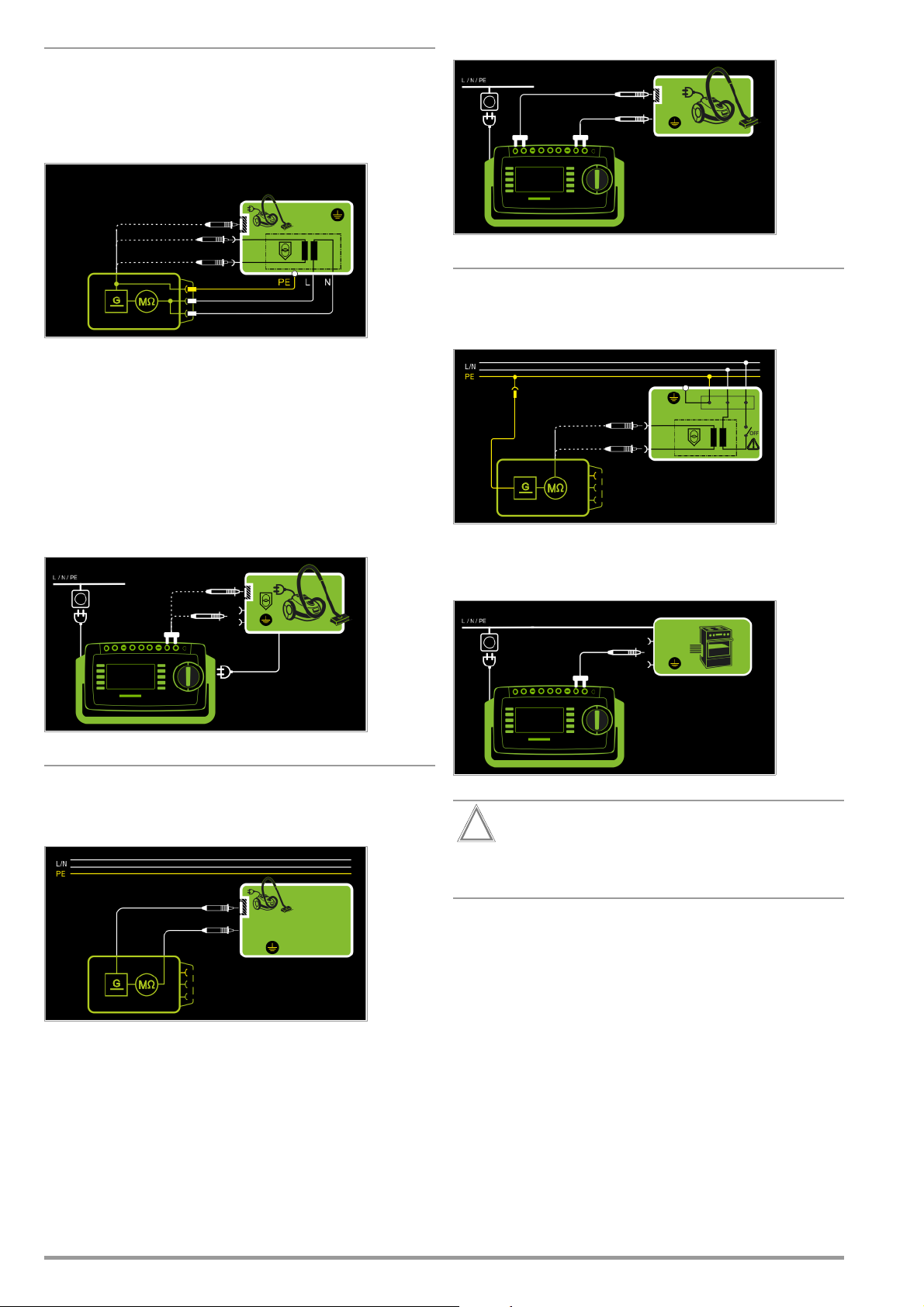
Protection Category I Devices
Attention!
!
Voltage
and Exposed Conductive Parts
with Outputs for Safety Extra-Low
– Measurement type LN(TS) - P1
– DUT mains plug to test socket
– Test probe P1 to P1 terminals
Schematic Diagram
Insulation resistance is measured successively between short-circuited mains terminals (L-N) and the safety extra-low voltage outputs which can be contacted with test probe P1, as well as external conductive parts which are not connected to the housing.
If measuring points should be contacted one after the other, this
is indicated by a dashed line. However, there are two parallel
measuring circuits for the RISO measurement with the LN(TS) –
P1//PE(TS) measuring parameter, which are established simultaneously to the short-circuited L and N conductors: one insulation
resistance is measured via PE at the test socket and, at the same
time, a second insulation resistance is measured via test probe
P1.
Wiring Diagram
Wiring Diagram
Special Case: Permanently Installed Protection Category I Devices
– Measurement type PE(mains) - P1
– Test probe P1 to P1 terminals
Schematic Diagram
Insulation resistance is measured successively between PE at the
mains connection and the extra-low voltage inputs by contacting
each of them with test probe P1.
Wiring Diagram
2-Pole Measurement at Protection Category I Housing Parts
(only with SECUTEST PRO or feature H01)
– Measurement type P1 - P2
Schematic Diagram
Insulation resistance is measured between external conductive
parts which can be contacted from the outside with test probe P2
and are not connected to the housing, and the housing with test
probe P1.
Deactivate the electrical system which supplies power to
the device under test before connecting the test instrument!
➭ Remove the mains fuses from the device under test and dis-
connect neutral conductor N inside the device under test.
➭ Connect test probe P1 to phase conductor L at the device
under test in order to measure insulation resistance.
32 GMC-I Messtechnik GmbH
Page 33
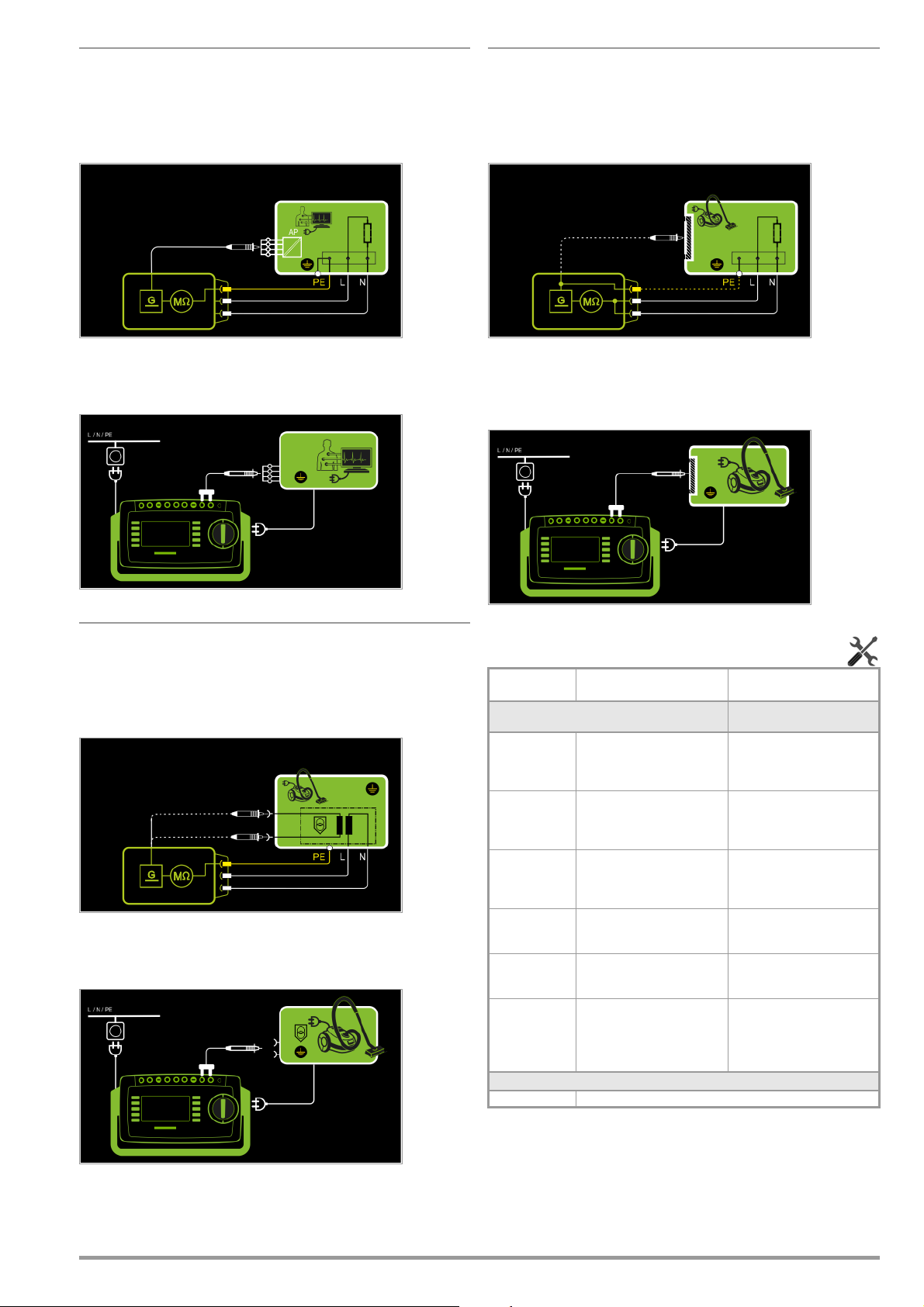
Protection Category I Devices
with Terminals for Applied Parts
– Measurement type PE(TS) - P1
– DUT mains plug to test socket
– Test probe P1 to P1 terminals
Schematic Diagram
Protection Category I Devices
with Exposed Conductive Parts
– Measurement type LN(TS) - P1//PE(TS)
– DUT mains plug to test socket
– Test probe P1 to P1 terminals
Schematic Diagram
Insulation resistance is measured between protective conductor
terminal PE and external, short-circuited applied parts which can
be contacted with test probe P1.
Wiring Diagram
Protection Category I Devices
Voltage
with
Outputs for Safety Extra-Low
– Measurement type PE(TS) - P1
– DUT mains plug to test socket
– Test probe P1 to P1 terminals
Schematic Diagram
Insulation resistance is measured between the PE terminal and
the safety extra-low voltage outputs, which must be contacted
one after the other with probe P1.
Wiring Diagram
Insulation resistance is measured between short-circuited mains
terminals (L-N) and external conductive parts which can be contacted with test probe P1 and are not connected to the housing,
as well as protective conductor terminal PE at the housing.
Wiring Diagram
Setting Measuring Parameters for RINS
Measuring
Parameter
Measurement Type
LN(TS)-PE(TS) PC I: Testing is conducted be-
LN(TS)-P1 Testing is conducted between
P1 – P2
PE(mains)-P1
PE(TS)-P1
LN(TS)-P1 //
PE(TS)
UISO(set)
> 50 ... < 500 V Variable test voltage can be entered with the numeric keypad
Meaning
tween short-circuited LN mains
terminals at the test socket and
the DUT’s PE terminal
short-circuited LN mains terminals at the test socket and test
probe P1.
SECUTEST PRO or feature H01:
2-pole measurement between
test probes 1 and 2 (see section
6.6)
Cable test: Testing is conducted
between the ground terminal at the
mains and test probe P1.
Testing is conducted between the
PE terminal at the test socket and
test probe P1.
Testing is conducted between
short-circuited LN mains terminals at the test socket
probe P1, including PE at the test
socket.
and test
Suitable for
DUT Connection via
Test socket, EL1, VL2E,
AT3 adapter (AT3-I I I E, AT3-IIS,
AT3-IIS32), AT16DI/AT32DI,
CEE Adapter
Test socket, VL2E,
AT3 adapter (AT3-I I I E, AT3-IIS,
AT3-IIS32), AT16DI/AT32DI,
No connection (PC3)
Permanent connection
Test socket
Test socket, VL2E,
AT3 adapter (AT3-I I I E, AT3-IIS,
AT3-IIS32), AT16DI/AT32DI,
GMC-I Messtechnik GmbH 33
Page 34
Test Sequence
Attention!
!
Note
Attention!
!
Attention!
!
Attention!
!
Note
Attention!
!
Prerequisite for Testing
The measurement of insulation resistance may not be
conducted on protection category I devices which have
not passed the protective conductor resistance test.
The insulation test cannot be performed for all DUTs, for
example electronic devices, EDP equipment, medical
devices etc. Leakage current measurements must be
performed for these DUTs (see Section 8.7).
Observe the notes in the service instructions.
In order to prevent damage to the instrument, measurement of insulation resistance may only be performed between application parts, measurement inputs or
interfaces and the protective conductor or the housing if
the instrument is laid out for measurements of this type.
Touching the DUT During Measurement
Testing is conducted with up to 500 V, and although current is limited (I < 3.5 mA), if the DUT is touched electrical
shock may occur which could result in consequential accidents.
Switch Settings at the DUT
All switches at the DUT must be set to the on position
during measurement of insulation resistance, including
temperature controlled switches and temperature regulators as well.
Measurement must be performed in all program steps
for devices equipped with program controllers.
➭ Set the rotary switch to the R
➭ Select the measurement type:
– By setting the parameters
or
– Directly via the Measurement Type key
➭ Select the test voltage.
The Up– and Up+ keys provide you with direct access to the
test voltage parameters: each time this key is pressed, the
setpoint value shown in the measuring window, Up(set), is reduced or increased by 10 V.
➭ Connect the DUT to the test socket.
➭ Start the test: press the START/STOP key.
position.
ISO
Removing the Connector Cable
Do not remove the DUT’s connector cable until the test
has been stopped, in order to assure that the capacitors
have been discharged.
➭ End the test: press the START/STOP key.
The save symbol appears (floppy disk showing the
number of measured values stored to buffer memory)
and prompts you to save the measured values to an ID
number.
➭ Read the measured values and compare them with the
table of permissible limit values.
➭ Press the ESC key in order to discard the measured
values stored to buffer memory and acknowledge by
pressing the key shown at the right.
Minimum Permissible Limit Values for Insulation Resistance
R
Test Standard Test voltage
VDE 07010702:2008
DIN EN 60974-4
VDE 05444:2017-05
* With activated heating elements
(where heating power > 3.5 kW and R
is required)
Test Standard Test voltage
IEC 62353
(VDE 0751-1)
500 V
LN → PE
1MΩ 2MΩ 5MΩ 0.25 MΩ 0.3 MΩ *
2MΩ 5MΩ 5MΩ
500 V
LN →
Probe
< 0.3 MΩ: leakage current measurement
INS
PC I PC II
2MΩ 7MΩ
BF or CF BF or CF
70 MΩ 70 MΩ
INS
Probe →
PE
R
INS
PC III Heating
Notes
Insulation resistance and/or leakage current must be measured
by contacting all exposed, conductive parts with test probe P1 for
protection category II and III devices, as well as for battery powered devices.
Batteries must be disconnected during testing of battery powered
devices.
➭ Switch the device under test on.
The measurement is disabled if a voltage of greater than
25 V is measured between the terminals.
➭ The measured values are displayed. The measured
value recording symbol shown at the right appears.
Each time this key is pressed, the currently displayed
measured value is saved to buffer memory.
➭ Turn off the device under test.
34 GMC-I Messtechnik GmbH
Page 35
8.7 Measuring Leakage Current
Attention!
!
10 10210310410510
6
+20
0
–20
–40
–60
Frequency (f) in Hz
Relative magnitude (dB): 20 log
U(f)
U(f=10)
Measurement with DUT Connected to Line Voltage
It’s absolutely essential to assure that the device under
test is operated with line voltage during performance of
leakage current measurements with the direct or differential
current method. Exposed conductive parts may conduct
dangerous touch voltage during testing, and may not
under any circumstances be touched. (Mains power is
disconnected if leakage current exceeds approx.
10 mA.)
Frequency response in
accordance with the
figure to the right is
taken into consideration for all leakage
current measurements (IPE, IT, IE, IP)
(direct, differential,
alternative).
GMC-I Messtechnik GmbH 35
Page 36
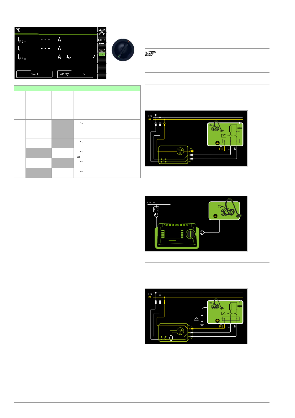
8.7.1 Protective Conductor Current – IPE
Note
I
PE
Protective Conductor Current Measuring Method (Direct Measurement)
The device under test is operated with mains power. Current
which flows through the PE conductor to earth at the mains side
of the device connection is measured.
Regardless of the currently selected connection type, all
help images and schematic diagrams can be queried for
the selected measuring function.
Single measurements, rotary switch level: green
Measurement Type,
with Mains
to Test Socket
Measurement Type,
without
Mains
Measuring Functions
to Test
Switch
Position
Direct
Differential
I
PE
AT3 adapter
1
Adapter
AT3-IIIE,
Voltage measuring inputs for leakage current measurement with differential method with SECUTEST PRO only (or instrument with feature I01)
2
Voltage measuring inputs for leakage current measurement with differential method and use of a current cleanup sensor with SECUTEST PRO only (or an instrument
with feature I01)
Socket
Alternative
1
Clamp 2
AT3-II S or AT3-II S32:
I
Protective conductor current, RMS
PE
I
AC component
PE~
I
DC component
PE=
U
Test vo l t a g e
LN
I
Protective conductor current, RMS
PE
U
Test vo l t a g e
LN
Protective conductor current, RMS
I
PE
U Test voltage
I
Protective conductor current, RMS
PE
U
Test vo l t a g e
LN
Protective conductor current, RMS
I
PE
U
Test vo l t a g e
LN
Applications
Protective conductor current must be measured for protection
category I devices.
Direct Measuring Method
– Direct measurement type
– DUT mains plug to test socket
Schematic Diagram
The device under test is operated with mains power.
Protective conductor current is measured between the protective
conductor at the mains and the protective conductor terminal at
the DUT via the DUT’s mains cable.
Wiring Diagram
Definition of Protective Conductor Current (direct measurement)
Current which flows through the protective conductor in the case
of housings which are isolated from ground.
Definition of Differential Current
Sum of instantaneous current values which flow via the L and N
conductors at the device’s mains connection. Differential current
is practically identical to fault current in the event of an error. Fault
current: current which is caused by an insulation defect, and
which flows via the defective point.
Definition of Alternative Measuring Method (equivalent leakage
current)
Equivalent leakage current is current which flows through the
active conductors of the device which are connected to each
other (L/N) to the protective conductor (SC1), or to the exposed,
conductive parts (SC2).
Differential Current Measuring Method
The device under test is operated with mains power. The sum of
the momentary values of all currents which flow through all active
conductors (L/N) at the mains side of the device connection is
measured. The measurements must be performed with mains
plug polarity in both directions.
Alternative Measuring Method (equivalent leakage current)
A high-impedance power supply is connected between the shortcircuited mains terminals and all exposed metal parts of the housing (which are connected to one another).
Current which flows over the insulation at the device under test is
measured.
Differential current measurement
– Differential measurement type
– DUT mains plug to test socket
Schematic Diagram
The device under test is operated with mains power.
Differential current is measured between mains conductors L and
N (current clip concept).
36 GMC-I Messtechnik GmbH
Page 37
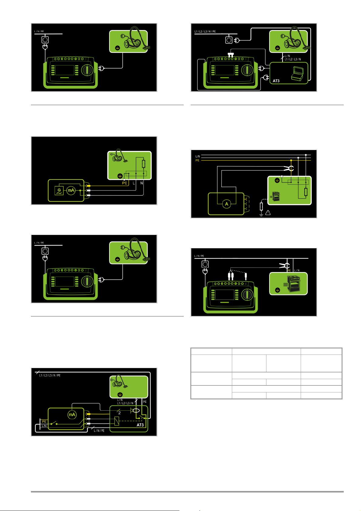
Wiring Diagram
Wiring Diagram (AT3-IIIE probe to COM-V)
Alternative Measuring Method (equivalent leakage current)
– Alternative measurement type
– DUT mains plug (protection category I) to test socket
Schematic Diagram
After activating test voltage, leakage current is measured via the
DUT’s mains cable between short-circuited mains conductors L
and N and the protective conductor terminal at the DUT.
Wiring Diagram
Measurement of protective conductor current via current clamp
sensor with voltage output for permanently installed DUTs
(only with SECUTEST PRO or feature I01 with optional current
clamp sensor)
– Clamp measurement type
Schematic Diagram
Measurement of protective conductor current by closing the current clamp sensor around mains cable PE for permanently
installed protection category I devices under test
Wiring Diagram (current clamp sensor to COM-V)
Connection of 3-phase DUTs (only with SECUTEST PRO or feature
I01 with optional test adapter AT3-IIIE)
– AT3-Adapter Measurement type
– DUT mains plug to AT3-IIIE test adapter
– AT3-IIIE probe to COM-V terminals
– AT3-IIIE test plug to test socket
Schematic Diagram
Measurement of the DUT with 3-phase mains connection via
AT3-IIIE adapter
GMC-I Messtechnik GmbH 37
Set Measuring Range at Current Clamp Sensor and Parameter at the
SECUTEST PRO
SECUTEST PRO Clamp SECUTEST PRO
Transformation Ratio
Parameter
1 mV : 1 mA
100 mV : 1 mA
* Only with WZ12C
** Default value
Transformation
Ratio
(switch *)
1 mV : 1 mA 1 mA ... 15 A 0 mA ... 300 A
SECUTEST CLIP
100 mV : 1 mA 0.1 ... 25 mA 0.00 mA ... 3.00 A
WZ12C
Measuring
Range
Display Range
with Clamp
Page 38
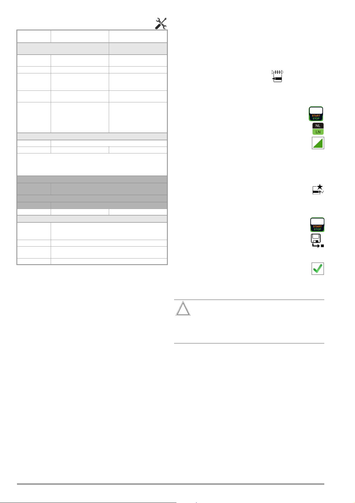
Setting Measuring Parameters for IPE Test Sequence for Direct Measuring Method
Attention!
!
➭ Before conducting any leakage current measurements, make
Measuring
Meaning
Parameter
Measurement Type
Direct Direct measuring method Test socket,
Differential Differential current measurement Test socket
Alternative Equivalent leakage current
AT3 adapter
Clamp
method
SECUTEST PRO or feature I01:
measurement with
SECUTEST PRO
Measurement of protective conductor current via current clamp
sensor with voltage output, and
conversion to and display as current values.
AT3 adapter
or feature I01:
Suitable for
DUT Connection via
AT16DI/AT32DI (direct or diff.)
Test socket, VL2E, AT3 adapter
(AT3-IIIE, AT3-IIS, AT3-IIS32),
AT16DI/AT32DI
AT3-III E, AT3-I IS, AT3-IIS32
Permanent connection
Polarity – for direct and differential measurement type only
L/N or N/L Selection of polarity for mains voltage to the test socket
The U (setpoint) and frequency (setpoint) measuring parameters for the “Alternative” measurement type are no longer included as of firmware version 1.7.0.
These parameters apply to individual measurements as well as test sequences
and have to be entered in SETUP (see section section 6.2).
U(set) – for alternative measurement type only
110 V, 115 V,
220 V, 230 V, 240 V
Selection of a line voltage for synthetic test voltage
Frequency(set) – for alternative measurement type only
48 Hz ... 400 Hz
Selection of a line frequency for synthetic test voltage
Clamp factor – only for clamp measurement type
1 mV : 1 mA Transformation ratio of the WZ12C current clamp sensor.
10 mV : 1 mA
100 mV:1 mA Transformation ratio of the SECUTEST CLIP current clamp sensor.
1 V : 1 A
For setting the current clamp factor at the WZ12C clamp and the
SECUTEST PRO (see table above).
For setting the current clamp factor at the SECUTEST PRO.
sure that the “Ref. voltage L-PE” and “Testingfreq. Alt” measurement parameters have been correctly set in SETUP (see
section 6.2).
➭ Set the rotary switch to the IPE position.
➭ Select the Direct measurement type:
– By setting the parameters
or
– Directly via the Measurement Type key
➭ Connect the DUT’s mains plug (protection category I) to the
test instrument’s test socket.
➭ Make sure that the device under test is switched off.
➭ Start the test: press the START/STOP key.
➭ Switch the device under test on.
➭ The measurement must be performed with mains plug
polarity in both directions by pressing the NL/LN key.
➭ Acknowledge the warning which indicates that line
voltage will be connected to the test socket.
➭ Switch the device under test on.
➭ Contact all accessible conductive parts, one after the other,
with test probe P1, which are not connected to the housing,
as well as any output sockets for safety extra-low voltage if included.
➭ The measured values are displayed. The measured
value recording symbol shown at the right appears.
Each time this key is pressed, the currently displayed
measured value is saved to buffer memory.
➭ Turn off the device under test.
➭ End the test: press the START/STOP key.
The save symbol appears (floppy disk showing the
number of measured values stored to buffer memory)
and prompts you to save the measured values to an ID
number.
➭ Read the measured values and compare them with the table
of permissible limit values.
➭ Press the ESC key in order to discard the measured
values stored to buffer memory and acknowledge by
pressing the key shown at the right.
Test Sequence with AT3-IIIE Adapter
Please observe the operating instructions for the AT3-IIIE
regarding correct connection of the test adapter and the device under test, as well as peculiarities involved in the test
sequence.
38 GMC-I Messtechnik GmbH
Page 39

Test Sequence with Differential Current Method
➭ Before conducting any leakage current measurements, make
sure that the “Ref. voltage L-PE” and “Testingfreq. Alt” measurement parameters have been correctly set in SETUP (see
section 6.2).
➭ Set the rotary switch to the IPE position.
➭ Select the Differential measurement type:
– By setting the parameters
or
– Directly via the Measurement Type key
➭ Connect the test object’s mains plug (protection category I) to
the test instrument’s test socket.
➭ Start the test: press the START/STOP key.
➭ The measurement must be performed with mains plug
polarity in both directions by pressing the NL/LN key.
➭ Acknowledge the warning which indicates that line
voltage will be connected to the test socket.
➭ Switch the device under test on.
➭ The measured values are displayed. The measured
value recording symbol shown at the right appears.
Each time this key is pressed, the currently displayed
measured value is saved to buffer memory.
➭ Turn off the device under test.
➭ End the test: press the START/STOP key.
The save symbol appears (floppy disk showing the
number of measured values stored to buffer memory)
and prompts you to save the measured values to an ID
number.
➭ Read the measured values and compare them with the table
of permissible limit values.
➭ Press the ESC key in order to discard the measured
values stored to buffer memory and acknowledge by
pressing the key shown at the right.
Maximum Permissible Limit Values for Leakage Current in mA
Test Standard I
VDE 0701-0702:2008
DIN EN 60974-4
VDE 0544-4:2017-05
* For devices with heating power of greater than 3.5 kW
Note 1: Devices which are not equipped with accessible parts that are connected to
the protective conductor, and which comply with requirements for touch current and, if applicable, patient leakage current, e.g. computer equipment with
shielded power pack
Note 2: Permanently connected devices with protective conductor
Note 3: Portable X-ray devices with mineral insulation
Key
IPECurrent in the protective conductor (primary leakage current)
PE
PC I: 3.5
1 mA/kW *
5 mA
Test Sequence for Alternative Measuring Method
➭ Before conducting any leakage current measurements, make
sure that the “Ref. voltage L-PE” and “Testingfreq. Alt” measurement parameters have been correctly set in SETUP (see
section 6.2).
➭ Set the rotary switch to the IPE position.
➭ Select the Alternative measurement type:
– By setting the parameters
or
– Via the Measurement Type key
➭ Connect the DUT’s mains plug (protection category I) to the
test instrument’s test socket.
➭ Start the test: press the START/STOP key.
➭ Switch the device under test on.
➭ The measured values are displayed. The measured
value recording symbol shown at the right appears.
Each time this key is pressed, the currently displayed
measured value is saved to buffer memory.
➭ End the test: press the START/STOP key.
The save symbol appears (floppy disk showing the
number of measured values stored to buffer memory)
and prompts you to save the measured values to an ID
number.
➭ Read the measured values and compare them with the table
of permissible limit values.
➭ Press the ESC key in order to discard the measured
values stored to buffer memory and acknowledge by
pressing the key shown at the right.
GMC-I Messtechnik GmbH 39
Page 40
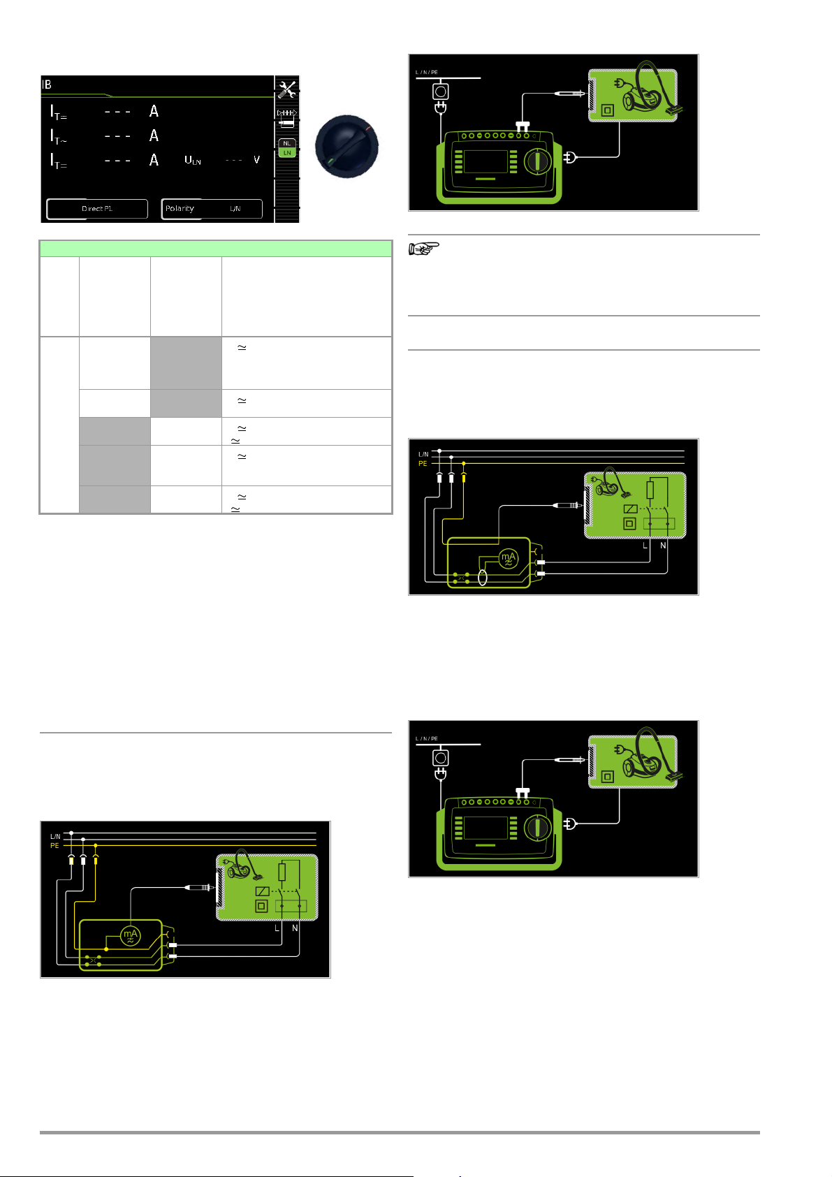
8.7.2 Touch Current – IB
Note
I
B
Wiring Diagram
Single measurements, rotary switch level: green
Switch
I
B
Measurement Type,
with Mains
to Test
Socket
Position
Direct P1
Differential P1
Measurement Type,
without
Mains
to Test
Socket
Alternative P1
Permanently
connected P1
Alternative
P1–P2
Measuring Functions
I
Touch current, TRMS
T
I
AC component
T~
I
DC component
T=
U
Test vo l t a g e
LN
I
Touch current, TRMS
T
U
Test vo l t a g e
LN
Touch current, TRMS
I
T
U Test voltage
Touch current, TRMS
I
T
I
AC component
T~
I
DC component
T=
I
Touch current, TRMS
T
U Test voltage
Applications
Make sure that the contacted parts are not grounded.
Definition
Current which flows from housing parts which are not connected
to the protective conductor via an external conductive connection
to earth or another part of the housing. Flow of current via the
protective conductor is excluded in this case.
The following designations are also common:
housing leakage current, probe current.
regarding protection category I DUTs:
Parts may or may not be grounded.
Coincidental grounding only occurs in the event of an
error.
Differential Current Method
– Measurement type differential P1
– DUT mains plug to test socket
– Test probe P1 to P1 terminals
Schematic Diagram
The device under test (PC2) is operated with mains power. Differential current which flows via the two mains conductors is measured (current clamp measurement concept). The measurements
must be performed with mains plug polarity in both directions.
Polarity is reversed with the NL/LN key. The current’s AC component is measured. Accessible conductive parts must be contacted with test probe P1.
Wiring Diagram
Direct measuring method
– Measurement type direct P1
– DUT mains plug to test socket
– Test probe P1 to P1 terminals
Schematic Diagram
The device under test is operated with mains power. Current
which flows to the protective conductor via exposed conductive
parts is measured by means of the probe. The measurements
must be performed with mains plug polarity in both directions.
Polarity is reversed with the NL/LN key. The TRMS, the AC or the
DC component of the current is measured.
40 GMC-I Messtechnik GmbH
Page 41

Alternative Measuring Method (equivalent leakage current)
– Measurement type alternative P1
– DUT mains plug to test socket
– Test probe P1 to P1 terminals
Schematic Diagram
Alternative measuring method with 2-pole measurement (P1–P2)
– Alternative measurement type (P1 - P2)
– Test probe P1 to P1 terminals
– Test probe P2 to P2 terminals
Schematic Diagram
After activating test voltage, leakage current is measured between
short-circuited mains conductors L and N (DUT mains plug) and
accessible conductive parts (probe contact). The TRMS, the AC
or the DC component of the current is measured.
Wiring Diagram
Direct Measuring Method for Permanently Installed DUTs
– Measurement type permanent connection P1
– Test probe P1 to P1 terminals
Schematic Diagram
The DUT is operated with line voltage from a permanent installation. Leakage current is measured between the protective conductor at the mains and the output sockets for safety extra-low
voltage at the DUT, one after the other, with the help of the test
probe. Furthermore, accessible, conductive parts which are not
connected to the housing must also be contacted.
Wiring Diagram
Touch current is measured between external conductive parts
which can be contacted with test probe P2 and are not connected
to the housing, and the housing with test probe P1.
Wiring Diagram
Setting Measuring Parameters for IT
Measuring
Parameter
Measurement
Typ e
Direct P1 Direct measuring method Test socket, AT3 adapter
Differential P1 Differential current measurement Test socket
Alternative P1 Equivalent leakage current
Permanently
connected P1
Alternative P1–P2
Polarity – for direct and differential measurement type only
L/N or N/L Selection of polarity for mains voltage to the test socket
The U (setpoint) and frequency (setpoint) measuring parameters for the “Alternative” measurement type are no longer included as of firmware version 1.7.0.
These parameters apply to individual measurements as well as test sequences
and have to be entered in SETUP (see section section 6.2).
U(set) – for measurement type alternative P1 only
110 V, 115 V,
220 V, 230 V, 240 V
Frequency(set) – for measurement type alternative P1 only
48 Hz ... 400 Hz Selection of a line frequency for synthetic test voltage
Meaning
Suitable for
DUT Connection via
(AT3-III E, AT3-I IS, AT3-IIS32),
AT16DI/AT32DI
method
Permanently installed DUT Permanent connection
Equivalent leakage current
method with SECUTEST PRO or
feature H01
Selection of a line voltage for synthetic test voltage
Test socket, AT3 adapter
(AT3-III E, AT3-I IS, AT3-IIS32),
AT16DI/AT32DI, VL2E
No connection, PC3:
2-pole measurement between
test probes 1 and 2 (see section
6.6)
GMC-I Messtechnik GmbH 41
Page 42

Direct Selection – Setting Polarity
Attention!
!
– for Direct and Differential Only
Measuring
Parameter
Measurement Type
L/N or N/L Selection of polarity for mains voltage to the test socket
Meaning
Prerequisites for Touch Current Measurement
• Visual inspection has been passed.
• For protection category I devices
Protective conductor resistance testing has been passed.
• Insulation resistance testing has been passed.
Test Sequence for Direct and Differential Current Methods
➭ Before conducting any leakage current measurements, make
sure that the “Ref. voltage L-PE” and “Testingfreq. Alt” measurement parameters have been correctly set in SETUP (see
section 6.2).
➭ Set the rotary switch to the I
➭ Select measurement type Direct P1 or Differential P1:
– By setting the parameters
or
– Via the Measurement Type key
➭ In the case of direct and differential current measurement,
measurement must be performed with mains plug polarity in both directions. Select the respective polarity
to this end by pressing the NL/LN key.
➭
Connect the DUT’s mains plug (protection category II) to the test
instrument’s test socket.
position.
B
Test Sequence for Alternative Measuring Method
➭ Before conducting any leakage current measurements, make
sure that the “Ref. voltage L-PE” and “Testingfreq. Alt” measurement parameters have been correctly set in SETUP (see
section 6.2).
➭ Set the rotary switch to the IB position.
➭ Select measurement type Alternative P1
or Alternative P1–P2 (feature H01):
– By setting the parameters
or
– Directly via the Measurement Type key
➭ Connect the DUT’s mains plug (protection category II) to the
test instrument’s test socket.
➭ Start the test: press the START/STOP key.
➭ Contact all accessible conductive parts, one after the
other, which are not connected to the housing with
test probe P1.
➭ The measured values are displayed. The measured
value recording symbol shown at the right appears.
Each time this key is pressed, the currently displayed
measured value is saved to buffer memory.
➭ End the test: press the START/STOP key.
The save symbol appears (floppy disk showing the
number of measured values stored to buffer memory)
and prompts you to save the measured values to an ID
number.
➭ Read the measured values and compare them with the
table of permissible limit values.
➭ Press the ESC key in order to discard the measured
values stored to buffer memory and acknowledge by
pressing the key shown at the right.
Testing is conducted in the presence of line voltage.
➭ Start the test: press the START/STOP key.
➭ Acknowledge the warning which indicates that line
voltage will be connected to the test socket.
➭ Switch the device under test on.
➭ Contact all accessible conductive parts, one after the other,
which are not connected to the housing with test probe P1.
➭ The measured values are displayed. The measured
value recording symbol shown at the right appears.
Each time this key is pressed, the currently displayed
measured value is saved to buffer memory.
➭ Turn off the device under test.
➭ End the test: press the START/STOP key.
The save symbol appears (floppy disk showing the
number of measured values stored to buffer memory)
and prompts you to save the measured values to an ID
number.
➭ Read the measured values and compare them with the
table of permissible limit values.
➭ Press the ESC key in order to discard the measured
values stored to buffer memory and acknowledge by
pressing the key shown at the right.
Maximum Permissible Limit Values for Leakage Current in mA
Test Standard I
VDE 0701-0702:2008 0.5
DIN EN 60974-4
VDE 0544-4:2017-05
Key
ITTouch current (leakage current from welding current)
T
10 mA
42 GMC-I Messtechnik GmbH
Page 43

8.7.3 Device Leakage Current – IG
I
G
Single measurements, rotary switch level: green
Measurement Type,
with Mains
to Test
Socket
Switch
Position
Direct
Differential
I
G
1
Adapter
AT3-IIIE,
Voltage measuring inputs for leakage current measurement with differential method with SECUTEST PRO only (or instrument with feature I01)
2
Voltage measuring inputs for leakage current measurement with differential method and use of a current cleanup sensor with SECUTEST PRO only (or an instrument
with feature I01)
Measurement Type,
without
Mains
to Test
Socket
Alternative
AT3 adapter 1
Clamp 2
AT3-II S or AT3-II S32:
Measuring Functions
I
Device leakage current, TRMS
E
I
AC component
E~
I
DC component
E=
U
Test vo l t a g e
LN
I
Device leakage current, TRMS
E
U
Test vo l t a g e
LN
Device leakage current, TRMS
I
E
U Test voltage
Device leakage current, TRMS
I
E
U
Test vo l t a g e
LN
Device leakage current, TRMS
I
E
U
Test vo l t a g e
LN
Applications
Measurement of device leakage current is required for medical electric devices in accordance with IEC 62353 (VDE 0751-1).
In the case of device leakage current as the sum of all leakage current, all probe contact points must be contacted simultaneously.
Definition
Device leakage current is the sum of all leakage currents from the
housing, accessible conductive parts and applied parts to PE.
If the DUT includes terminals for applied parts, they must be short-circuited and contacted with test probe P1 as well.
Wiring Diagram
Differential current measurement
– Differential measurement type
– DUT mains plug to test socket
– Test probe P1 to P1 terminals
Schematic Diagram, Protection Category I
The device under test (PC1) is operated with mains power.
Differential current which flows via the two mains conductors is
measured (current clamp measurement concept). The measurements must be performed with mains plug polarity in both directions. Polarity is reversed with the NL/LN key.
Short-circuited terminals for applied parts or accessible conductive parts which are not connected to the housing must be contacted with test probe P1.
Wiring Diagram, Protection Category I
Direct Measuring Method
– Direct measurement type
– DUT mains plug to test socket
– Test probe P1 to P1 terminals
Schematic Diagram
The device under test (PC1) is operated with mains power.
Protective conductor current is measured between the protective
conductor at the mains (test instrument supply power) and the
protective conductor terminal at the DUT via the DUT’s mains
cable. The measurements must be performed with mains plug
polarity in both directions. Polarity is reversed with the NL/LN key.
Accessible conductive parts which are connected to the housing,
as well as those which are not connected to the housing, must be
contacted with test probe P1.
Wiring Diagram, Protection Category II
GMC-I Messtechnik GmbH 43
Page 44

Alternative Measuring Method (equivalent leakage current)
– Alternative Measurement Type (P1)
– DUT mains plug connected to the test socket
– Test probe P1 to P1 terminals
Schematic Diagram, Protection Category I
After activating test voltage, leakage current is measured between
short-circuited mains conductors L and N (DUT mains plug) and
accessible conductive parts (probe contact) which are not con-
nected to the housing.
If the DUT includes terminals for applied parts, they must be
short-circuited and contacted with test probe P1 as well.
Wiring Diagram, Protection Category I
Measurement Method with Current Clamp Sensor
for Permanently Installed DUTs
– Clamp measurement type
– Clamp to COM-V (only with SECUTEST PRO or feature I01with
optional current clamp sensor)
Schematic Diagram
Measurement of device leakage current by closing the current
clamp sensor around the L and N conductors of the mains cable
for permanently installed protection category I devices under test
Wiring Diagram
Differential current measurement
– AT3-Adapter Measurement type
– DUT mains plug to AT3-IIIE test adapter
– Test probe P1 to P1 terminals
– AT3-IIIE probe to COM-V terminals
– AT3-IIIE test plug to test socket
Schematic Diagram
Measurement at the DUT with 3-phase mains connection via
AT3-IIIE adapter
Wiring Diagram
Set Measuring Range at Current Clamp Sensor and Parameter at the
SECUTEST PRO
SECUTEST PRO
Transformation Ratio
Parameter
1 mV : 1 mA
100 mV : 1 mA
* Only with WZ12C
** Default value
Transformation
(switch *)
1 mV : 1 mA 1 mA ... 15 A 0 mA ... 300 A
100 mV : 1 mA 0.1 ... 25 mA 0.00 mA ... 3.00 A
Clamp SECUTEST PRO
Ratio
SECUTEST CLIP
Measuring
Range
WZ12C
Display Range
with Clamp
44 GMC-I Messtechnik GmbH
Page 45

Setting Measuring Parameters for IE
Attention!
!
Measuring
Parameter
Measurement Type
Direct
Differential Differential current measurement Test socket
Alternative Equivalent leakage current mea-
AT3 adapter
Clamp
Polarity 1 – for direct, differential and AT3 adapter measurement types
only
L/N or N/L Selection of polarity for mains voltage to the test socket
The U (setpoint) and frequency (setpoint) measuring parameters for the “Alternative” measurement type are no longer included as of firmware version 1.7.0.
These parameters apply to individual measurements as well as test sequences
and have to be entered in SETUP (see section section 6.2).
U(set) – for alternative measurement type only
110 V, 115 V,
220 V, 230 V, 240 V
Frequency(set) – for alternative measurement type only
48 Hz ... 400 Hz
Clamp factor – only for clamp measurement type
1 mV : 1 mA Transformation ratio of the WZ12C current clamp sensor.
10 mV : 1 mA
100 mV:1 mA Transformation ratio of the SECUTEST CLIP current clamp sensor.
1 V : 1 A
1
Measurement must be performed with mains polarity in both directions. The largest value is documented
Meaning
Suitable for
DUT Connection via
Direct measuring method, optional
probe contact
suring method with probe contact
SECUTEST PRO or feature I01:
measurement with
SECUTEST PRO
Measurement of device leakage
current via current clamp sensor
with voltage output, and conversion to and display as current
values.
Selection of a line voltage for synthetic test voltage
Selection of a line frequency for synthetic test voltage
For setting the current clamp factor at the WZ12C clamp and the
SECUTEST PRO (see table above).
For setting the current clamp factor at the SECUTEST PRO.
AT3 adapter
or feature I01:
Test socket,
AT16DI/AT32DI
(only diff. is sensible)
Test socket, AT16DI/AT32DI
AT3-IIIE, AT3-IIS, AT3-IIS32
Permanent connection
Test Sequence
➭ Before conducting any leakage current measurements, make
sure that the “Ref. voltage L-PE” and “Testingfreq. Alt” measurement parameters have been correctly set in SETUP (see
section 6.2).
➭ Set the rotary switch to the IG position.
➭ Connect the DUT in accordance with the selected measuring
method.
➭ Select the measurement type:
– By setting the parameters
or
– Directly via the Measurement Type key
➭ As an alternative, you can select the measurement type
directly using the key shown at the right.
➭ In the case of direct and differential current measurement,
measurement must be performed with mains plug polarity in both directions. Select the respective polarity
to this end by pressing the NL/LN key.
➭ Start the test: press the START/STOP key.
➭ After each reconnection to the mains, and as soon as
the first test is started, a mains connection test is executed.
➭ In the case of the direct or differential measurement type:
Acknowledge the warning which indicates that line
voltage will be connected to the test socket.
➭ Switch the device under test on.
➭ The measured values are displayed. The measured
value recording symbol shown at the right appears.
Each time this key is pressed, the currently displayed
measured value is saved to buffer memory.
➭ Turn off the device under test.
➭ End the test: press the START/STOP key.
The save symbol appears (floppy disk showing the
number of measured values stored to buffer memory)
and prompts you to save the measured values to an ID
number.
➭ Read the measured values and compare them with the
table of permissible limit values.
➭ Press the ESC key in order to discard the measured
values stored to buffer memory and acknowledge by
pressing the key shown at the right.
Test Sequence with AT3-IIIE Adapter
Please observe the operating instructions for the AT3IIIE regarding correct connection of the test adapter and
the device under test, as well as peculiarities involved in
the test sequence.
Maximum Permissible Limit Values for Equivalent Leakage
Current in mA
Test Standard I
VDE 0701-0702
IEC 62353
(VDE 0751-1)
IGADevice leakage current
I
Equivalent leakage current
EA
PE Protective conductor
1
For devices with heating power ≥ 3.5 kW
2
This limit value is not taken into consideration in the DIN EN 62353
(VDE 0751-1) standard.
GA
PC I: 3.5 / 1 mA/kW
PC II: 0.5
1
Permanently connected devices with PE
Portable x-ray devices with additional PE
Portable x-ray devices without additional PE
I
EDL
PC I (PE or parts connected to PE)
Devices with mineral insulation
PC II
0.2
10
2
1
5
2
5
GMC-I Messtechnik GmbH 45
Page 46

8.7.4 Leakage Current from the Applied Part – IA
I
A
Single measurements, rotary switch level: green
Measurement Type,
with Mains
to Test
Socket
Switch
Position
Direct P1 I
I
A
Measurement Type,
without
Mains
to Test
Socket
Alternative P1
Permanently
connected P1
Measuring Functions
Current from the applied part
A
U
Test vo l t a g e
A
Direct measuring method
– Measurement type direct P1
– DUT Mains Plug (PC1) Connected to Test Socket
– Probe to P1 Terminal
Schematic Diagram
Alternative Measuring Method (equivalent patient leakage current)
– Measurement type alternative P1
– DUT Mains Plug (PC1) Connected to Test Socket
– Probe to P1 Terminal
Schematic Diagram
After activating test voltage, leakage current from the application
part is measured between short-circuited conductors L-N-PE
(DUT mains plug) and the short-circuited terminals of the applied
parts.
Wiring Diagram
The device under test (PC1) is operated with mains power.
The measurements must be performed with mains plug polarity in
both directions. Polarity is reversed with the NL/LN key. After acti-
vating test voltage and line voltage, leakage current from the application part is measured between the short-circuited terminals of
the applied parts and PE (DUT mains plug).
Wiring Diagram
Direct measuring method
– Measurement type permanent connection P1
– Permanent Connection
– Probe to P1 Terminal
Schematic Diagram
Leakage current from the application part is measured between
the short-circuited terminals of the application parts and PE at the
mains connection.
Wiring Diagram
46 GMC-I Messtechnik GmbH
Page 47

Setting Measuring Parameters for IA
I
P
8.7.5 Patient Leakage Current – IP
Measuring
Meaning
Parameter
Measurement Type
Direct P1 Direct measuring method (via
Alternative P1 Equivalent leakage current mea-
Permanently
connected P1
test socket) with test probe P1
suring method (via test socket)
with test probe P1
Direct measuring method Permanent connection
Suitable for
DUT Connection via
Test socket, AT3 adapter
(AT3-III E, AT3-I IS, AT3-IIS32),
AT16DI/AT32DI
Test socket
Phase angle – for direct P1 and permanent connection P1 only
0° or 180°
Selectable phasing for the internal generator relative to mains phasing
Polarity – for direct P1 only
L/N or N/L Selection of polarity for mains voltage to the test socket
The U (setpoint) and frequency (setpoint) measuring parameters for the “Alternative” measurement type are no longer included as of firmware version 1.7.0.
These parameters apply to individual measurements as well as test sequences
and have to be entered in SETUP (see section section 6.2).
U(set) – for alternative (P1) and permanent connection (P1) only
110 V, 115 V,
220 V, 230 V, 240 V
Selection of a line voltage for synthetic test voltage
Frequency(set) – for alternative P1 only
48 Hz ... 400 Hz
Selection of a line frequency for synthetic test voltage
Test Sequence
➭ Before conducting any leakage current measurements, make
sure that the “Ref. voltage L-PE” and “Testingfreq. Alt” measurement parameters have been correctly set in SETUP (see
section 6.2).
➭ Set the rotary switch to the IA position.
➭ Connect the DUT in accordance with the selected measuring
method.
➭ Select the measurement type:
– By setting the parameters
or
– Directly via the Measurement Type key
➭ In the case of direct measurement, measurement must
be performed with mains plug polarity in both directions. Select the respective polarity to this end by
pressing the NL/LN key.
➭ Start the test: press the START/STOP key.
➭ After each reconnection to the mains, and as soon as
the first test is started, a mains connection test is executed.
➭ – Measurement type direct P1 Acknowledge the warning
which indicates that line voltage will be connected to
the test socket.
➭ Switch the device under test on.
➭ Contact the short-circuited applied parts with the test probe.
➭ The measured values are displayed. The measured
value recording symbol shown at the right appears.
Each time this key is pressed, the currently displayed
measured value is saved to buffer memory.
➭ Turn off the device under test.
➭ End the test: press the START/STOP key.
The save symbol appears (floppy disk showing the
number of measured values stored to buffer memory)
and prompts you to save the measured values to an ID
number.
➭ Read the measured values and compare them with the
table of permissible limit values.
➭ Press the ESC key in order to discard the measured
values stored to buffer memory and acknowledge by
pressing the key shown at the right.
Single measurements, rotary switch level: green
Measurement Type,
with Mains
to Test
Socket
Switch
Position
Direct P1 I
I
P
Measurement Type,
without
Mains
to Test
Socket
Permanently
connected P1
Measuring Functions
Patient leakage current, TRMS
P
I
AC component
P~
I
DC component
P=
U
Test vo l t a g e
LN
Definition
Patient leakage current is the current which flows to ground or PE
from the patient ports at the running device via the patient.
The AC and the DC component of the current is measured.
Direct Measuring Method
– Measurement type direct P1
– DUT Mains Plug (PC1) Connected to Test Socket
– Probe to P1 Terminal
Schematic Diagram
After activating test voltage, patient leakage current is measured
at the DUT between PE (DUT mains plug) and the short-circuited
application parts.
Wiring Diagram
GMC-I Messtechnik GmbH 47
Page 48

Direct measuring method
– Measurement type permanent connection P1
– Permanent Connection
– Probe to P1 Terminal
Schematic Diagram
Patient leakage current is measured between the patient terminals and PE at the mains connection.
Wiring Diagram
Setting Measuring Parameters for IP
Measuring
Parameter
Measurement Type
Direct P1 Direct measuring method (via
Permanently
connected P1
Polarity – for direct P1 only
L/N or N/L Selection of polarity for mains voltage to the test socket
Meaning
Suitable for
DUT Connection via
Test socket
test socket) with test probe P1
Permanently installed DUT Permanent connection
Test Sequence
➭ Before conducting any leakage current measurements, make
sure that the “Ref. voltage L-PE” and “Testingfreq. Alt” measurement parameters have been correctly set in SETUP (see
section 6.2).
➭ Set the rotary switch to the I
➭ Connect the DUT to the test socket.
➭ Select the measurement type:
– By setting the parameters
or
– Directly via the Measurement Type key
➭ In the case of direct measurement P1, measurement
must be performed with mains plug polarity in both directions. Select the respective polarity to this end by
pressing the NL/LN key.
➭ Start the test: press the START/STOP key.
➭ After each reconnection to the mains, and as soon as
the first test is started, a mains connection test is executed.
➭ In the case of measurement type direct P1:
Acknowledge the warning which indicates that line
voltage will be connected to the test socket.
➭ Switch the device under test on.
➭ Contact the short-circuited inputs for the applied parts with
test probe P1.
➭ The measured values are displayed. The measured
value recording symbol shown at the right appears.
Each time this key is pressed, the currently displayed
measured value is saved to buffer memory.
➭ Turn off the device under test.
➭ End the test: press the START/STOP key.
The save symbol appears (floppy disk showing the
number of measured values stored to buffer memory)
and prompts you to save the measured values to an ID
number.
➭ Read the measured values and compare them with the table
of permissible limit values.
➭ Press the ESC key in order to discard the measured
values stored to buffer memory and acknowledge by
pressing the key shown at the right.
position.
P
Maximum Permissible Limit Values for Leakage Current in mA
I
Test Standard
IEC 62353
(VDE 0751-1)
EN 60601
48 GMC-I Messtechnik GmbH
Direct current 0.01 0.01 0.01
Alternating current 0.1 0.1 0.01
Direct current 0.01 0.01 0.01
Alternating current 0.1 0.1 0.01
Typ e B
P
Typ e BFTyp e
CF
Page 49

This page has been left blank intentionally.
GMC-I Messtechnik GmbH 49
Page 50
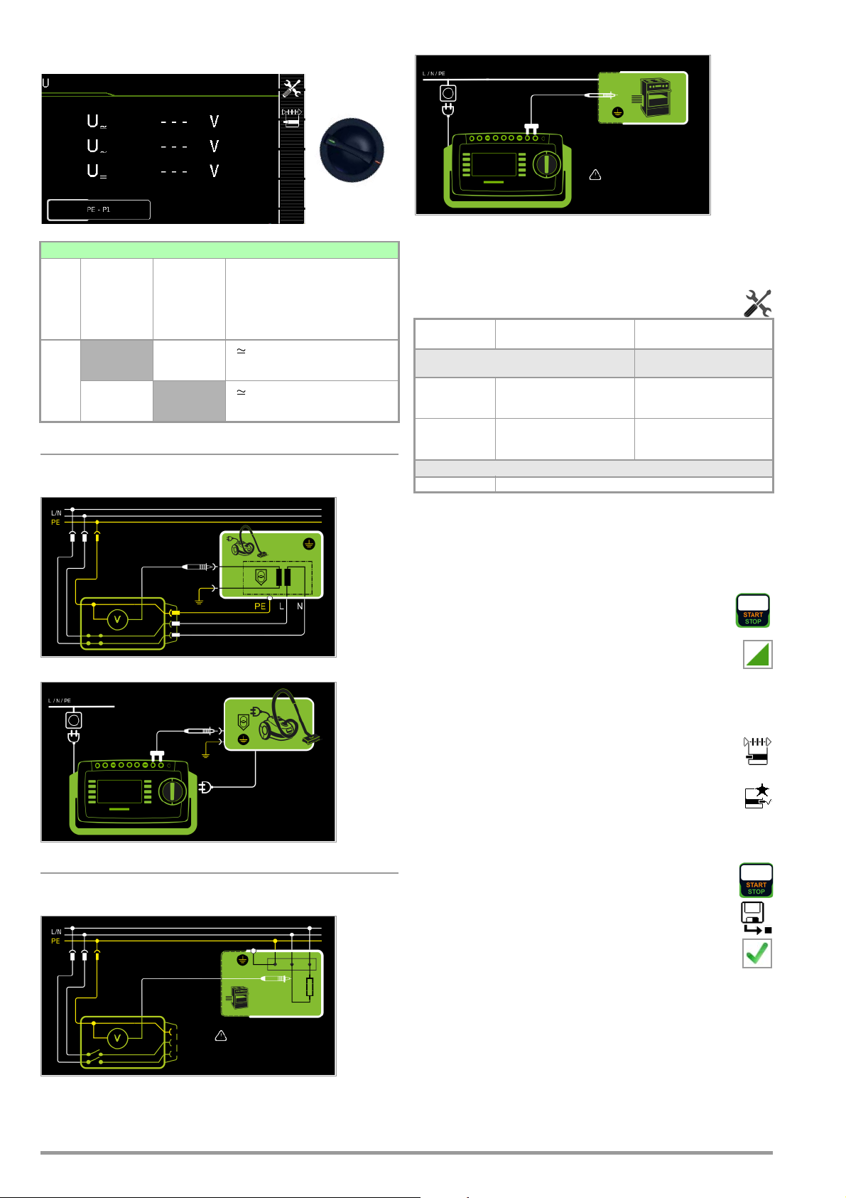
8.8 Probe Voltage – U
U
Wiring Diagram
Single measurements, rotary switch level: green
Switch
U
Measurement Type,
with Mains
to Test
Socket
Position
PE - P1
(with mains)
Measurement Type,
without
Mains
to Test
Socket
PE - P1
Measuring Functions
UProbe voltage, RMS
U
~
U
=
UProbe voltage, RMS
U
~
U
=
Mains to test socket
Schematic Diagram
Wiring Diagram
Permanently connected DUT
Schematic Diagram
Alternating voltage component
Direct voltage component
Alternating voltage component
Direct voltage component
Direct, alternating and pulsating voltages of up to 253 V can be
measured. Two connection types are available, one of which has
to be selected in the parameters menu.
Setting Measuring Parameters for U
Measuring
Meaning
Probe
Parameter
Measurement Type
PE-P1 Measurement of voltages with
PE-P1 (with
mains)
reference to PE, test socket
remains voltage-free
Measurement of voltages with
reference to PE, line voltage is
applied to the test socket
Suitable for
DUT Connection via
Permanent connection
Test socket
Polarity – only for PE-P1 (with mains)
L/N or N/L Selection of polarity for mains voltage to the test socket
Test Sequence
➭ Set the rotary switch to the U position.
➭ Connect the DUT’s mains plug to the test instrument’s test
socket.
➭ Start the test: press the START/STOP key.
➭ PE-P1 (with mains): Acknowledge the warning which in-
dicates that line voltage will be connected to the test
socket.
➭ Switch the device under test on.
➭ Contact the ungrounded output for safety extra-low voltage
with test probe P1.
➭ Polarity can be set via direct selection immediately be-
fore measurement is started, without having to switch to
the parameters menu.
➭ The measured values are displayed. The measured
value recording symbol shown at the right appears.
Each time this key is pressed, the currently displayed
measured value is saved to buffer memory.
➭ Turn off the device under test.
➭ End the test: press the START/STOP key.
The save symbol appears (floppy disk showing the
number of measured values stored to buffer memory)
and prompts you to save the measured values to an ID
number.
➭ Press the ESC key in order to discard the measured
values stored to buffer memory and acknowledge by
pressing the key shown at the right.
50 GMC-I Messtechnik GmbH
Page 51
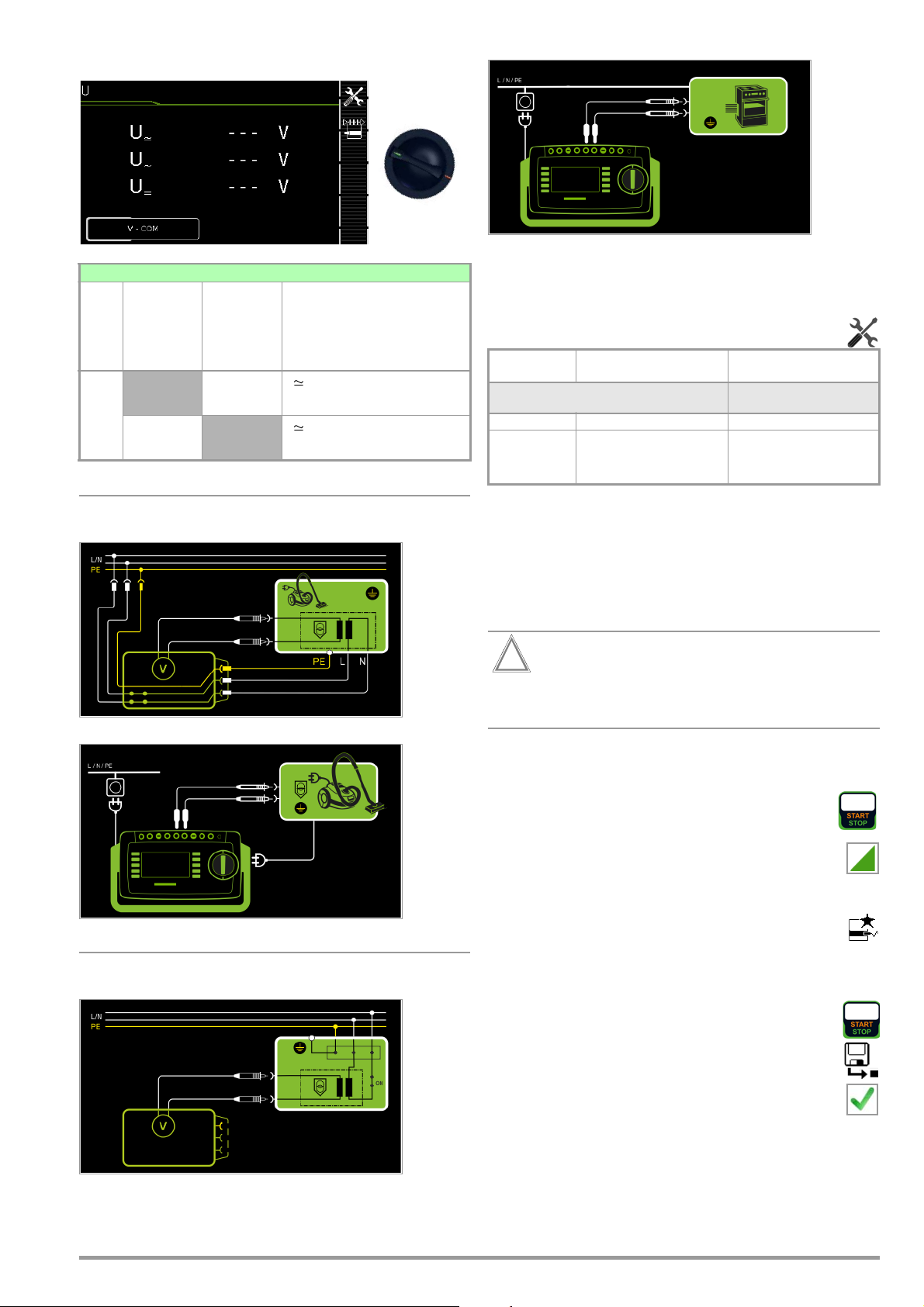
8.9 Measuring Voltage – U (SECUTEST PRO or feature I01 only)
Attention!
!
U
Single measurements, rotary switch level: green
Switch
U
Measurement Type,
with Mains
to Test
Socket
Position
V - COM
(with mains)
Measurement Type,
without
Mains
to Test
Socket
V – COM
Measuring Functions
U Measuring voltage, RMS
U
Alternating voltage component
~
U
Direct voltage component
=
U Measuring voltage, RMS
U
Alternating voltage component
~
U
Direct voltage component
=
Wiring Diagram
Direct, alternating and pulsating voltages of up to 253 V can be
measured between the V and COM socket terminals.
• Measurements with the voltage measuring input of the voltmeter function (V–COM), electrically isolated from the mains
Setting Measuring Parameters
Measuring
Parameter
Measurement Type
V – COM Display: RMS value + AC + DC Permanent connection
V – COM (with
mains)
Meaning
Display: RMS value + AC + DC;
with mains to test socket, e.g. for
measuring protective extra-low
voltage at power packs
Suitable for
DUT Connection via
Test socket
Mains to test socket
Schematic Diagram
Wiring Diagram
Permanently connected DUT
Schematic Diagram
Test Sequence, DUT at Test Socket (e.g. for measuring safety
extra-low voltage at power packs or chargers)
➭ Set the rotary switch to the U position.
➭ Set the parameter to V – COM (with mains).
➭ Connect the DUT’s mains plug to the test instrument’s test
socket.
Use only the included, contact-protected KS17-ONE
measurement cables when measuring dangerous voltage.
➭ Connect the DUT’s output sockets to the V and COM sockets,
e.g. in order to be able to measure a safety extra-low voltage at
the DUT’s output.
➭ Start the test: press the START/STOP key.
➭ V-COM (with mains) Acknowledge the warning which in-
dicates that line voltage will be connected to the test
socket.
➭ Switch the device under test on.
➭ The measured values are displayed. The measured
value recording symbol shown at the right appears.
Each time this key is pressed, the currently displayed
measured value is saved to buffer memory.
➭ Turn off the device under test.
➭ End the test: press the START/STOP key.
The save symbol appears (floppy disk showing the
number of measured values stored to buffer memory)
and prompts you to save the measured values to an ID
number.
➭ Press the ESC key in order to discard the measured
values stored to buffer memory and acknowledge by
pressing the key shown at the right.
GMC-I Messtechnik GmbH 51
Page 52
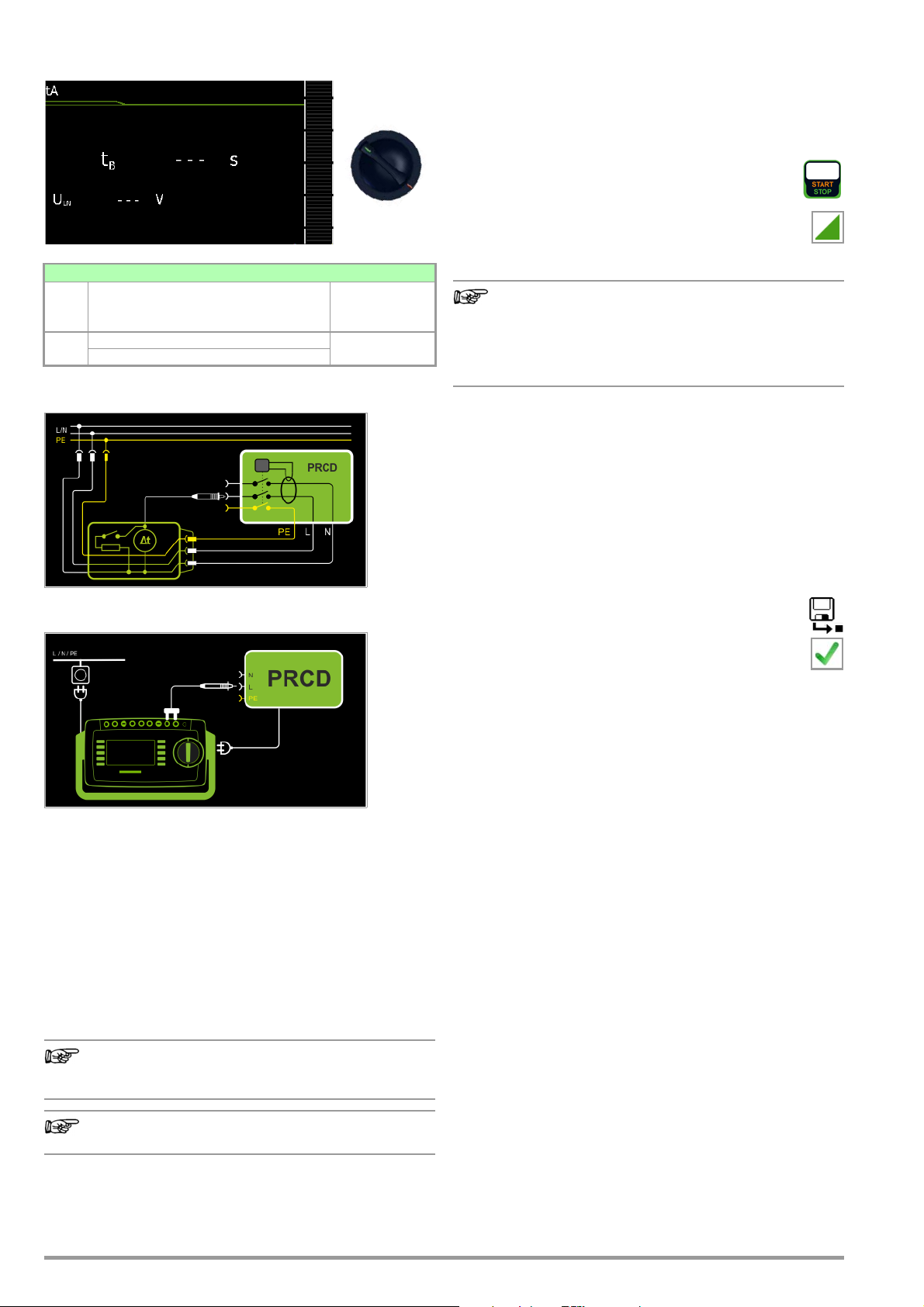
8.10 Measuring Time to Trip for RCDs of the Type PRCD – tA
Note
Note
Note
t
A
Test Sequence
➭ Set the rotary switch to the tA position.
➭ Plug the PRCD into the test socket at the test instrument and
connect the test probe to P1.
➭ Start the test: press the START/STOP key.
➭ Acknowledge the warning which indicates that line
voltage will be connected to the test socket.
Single measurements, rotary switch level: green
Measuring Functions Measurement
Switch
Position
ta
t
A
PRCD time to trip for 30 mA PRCD
U
Line voltage at the test socket
LN
Schematic Diagram
Wiring Diagram
Type, with Mains
to Test Socket
Execute the following steps when prompted to do so:
Please note that test probe P1 is in continuous contact
with the phase conductor from the point in time at which
the PRCD is plugged in until it trips. Premature disconnection of the test probe may result in erroneous measured values.
➭ After each reconnection to the mains, and as soon as the first
test is started, a mains connection test is executed.
➭ If the probe test has revealed that probe P1 was not con-
nected: connect probe P1 as described above.
➭ Switch the PRCD on after connection to line voltage (e.g.
reset button on PRCD).
➭ Contact neutral conductor L at the PRCD with test probe P1
(ascertain by trial and error if necessary).
➭ The test is automatically ended and time to trip is displayed
after the PRCD is tripped.
➭ The save symbol appears and prompts you to save the
measured values to an ID number.
➭ Press the ESC key in order to discard the measured
values stored to buffer memory and acknowledge by
pressing the key shown at the right.
Definition
According to DIN VDE 0100-600:2008, substantiation must be
provided that RCCBs are tripped within the time period specified
in DIN VDE 0100-410.
PRCD
Portable residual current device
Applications
The PRCD under test is plugged into the test socket at the test
instrument. The PRCD’s phase conductor must be contacted
with test probe P1 in order to trip the PRCD.
Testing of PRCDs (test sequences and time to trip) is only
possible for DUTs with a nominal voltage of 230 V.
Measurement of time to trip is not possible in IT systems.
52 GMC-I Messtechnik GmbH
Page 53
8.11 Function Test – P
Note
Attention!
!
Attention!
!
Attention!
!
P
Single measurements, rotary switch level: green
Measuring Functions Measurement
Switch
Position
P Function test at the test socket
I Current between L and N
U Voltage between L and N
f Frequency
P Active power
S Apparent power
PF Power factor
Schematic Diagram
Type, with Mains
to Test Socket
Selection of polarity
for mains voltage
The device under test can be subjected to a function test with
mains voltage via the integrated test socket.
The test socket is tested for short-circuiting before switching to
line voltage (a statement resulting from the short-circuit test can
only be made regarding the DUT itself when a single-phase DUT
is being tested).
In addition to testing with the selector switch in the function test
position, a function test can also be performed immediately after
safety testing has been passed in accordance with the selected
standard (not possible for protection category III devices).
Test Sequence
The function test may only be performed after the DUT
has successfully passed the safety test.
Refer to the safety precautions on page 5 with regard to
switching power consumers.
Wiring Diagram
Setting Measuring Parameters for P
Measuring Parameter Meaning
Polarity
LN Phase L – neutral conductor N
NL Neutral conductor N – phase L
The following connection types are possible:
• Test socket
• CEE adapter (only for connection via
single-phase CEE or “caravan socket”)
AT3 adapter (AT3-IIIE, AT3-IIS, AT3-IIS32)
•
• AT16DI/AT32DI
These or similar adapters can be used for the function test
(initial start-up of the DUT), but measurement of apparent
and active power, power factor and current consumption is
only possible when the DUT is directly connected to the test
socket or via the CEE adapter (single-phase CEE socket
only).
Starting the Function Test
For reasons of safety, the device under test must be
switched off before the function test is started. This precaution prevents inadvertent start-up of a DUT which
may represent a hazard during operation, e.g. a circular
saw or a disc grinder.
Ending the Function Test
After completion of the function test, DUTs must be
turned off with their own switch – especially devices with
relatively high inductivity.
➭ Set the rotary switch to the P position.
➭ Connect the DUT’s mains plug to the test instrument’s test
socket.
➭ Start the test: press the START/STOP key.
➭ Acknowledge the warning which indicates that line
voltage will be connected to the test socket.
➭ Switch the device under test on.
➭ The measured values are displayed. The measured
value recording symbol shown at the right appears.
Each time this key is pressed, the currently displayed
measured value is saved to buffer memory.
➭ Turn off the device under test.
➭ End the test: press the START/STOP key.
The save symbol appears (floppy disk showing the
number of measured values stored to buffer memory)
and prompts you to save the measured values to an ID
number.
➭ Press the ESC key in order to discard the measured
values stored to buffer memory and acknowledge by
pressing the key shown at the right.
GMC-I Messtechnik GmbH 53
Page 54
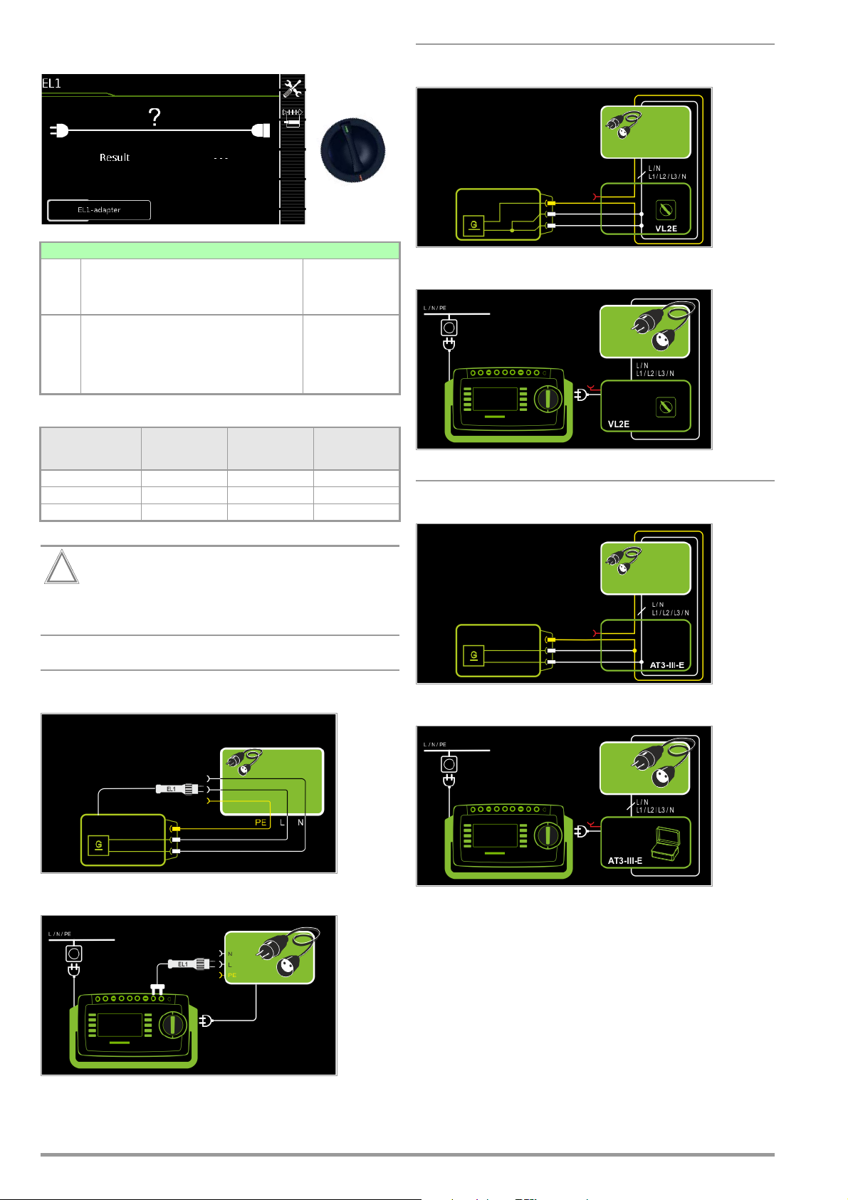
8.12 Testing Extension Cords for Correct Function – EL1
Attention!
!
EL1
Single measurements, rotary switch level: green
Measuring Functions Measurement
Switch
Position
Extension cord test
EL1
with adapter for single or 3-phase extension cords for
testing:
– Continuity
– Short-circuit
– Incorrect polarity (reversed wires *)
* No checking for reversed polarity takes place when the EL1 adapter is used.
Type, without
Mains to Test
Socket
EL1 adapter
AT3-IIIE adapter
VL2E adapter
Measurement at Single and 3-Phase Extension Cords with VL2E
Schematic Diagram
Wiring Diagram
Testing for Continuity
EL1 adapter
VL2E adapter
AT3-IIIE adapter
This function permits an evaluation of the continuity of
the active conductors L(1, 2, 3) and N of an extension
cord. The PE conductor is not tested in this case.
L(1/2/3), N
XX—
XXX
XXX
Short-circuiting
between:
L(1/2/3), N
Polarity reversal / clockwise
phase sequence
Measurement at Single-Phase Extension Cords with EL1
Schematic Diagram
Measurement at Single and 3-Phase Extension Cords with AT3-III E
Schematic Diagram
Wiring Diagram
Wiring Diagram
54 GMC-I Messtechnik GmbH
Page 55

Setting Measuring Parameters
Note
Attention!
!
Note
Note
Attention!
!
Testing for Continuity
EL1 adapter
VL2E adapter
AT3-IIIE adapter
See corresponding single measurements for the testing of RPE
and RINS.
See section 10, “Test Sequences in Accordance with
Standards” (switch setting A8) with regard to testing
extension cords per DIN VDE 0701-0702, for which RPE
and RINS are measured.
If the EL1 continuity test is conducted for an extension
cord in combination with a “travel adapter”, results provided by the test instrument indicating the correctness of
the extension cord’s polarity cannot be relied upon!
In the case of cables with indicator lamp (usually a glow lamp
in the switch), the results of the continuity test for L and N
may be distorted due to additional resistance caused by
the glow lamp.
In case of doubt, perform a continuity test for L and N by
means of resistance measurement (R-PE or R-INS):
SECUTEST PRO: R-PE between probe 1 and probe 2.
SECUTEST BASE(10):
ment cable at the protective conductor bar in the test socket
(test type PE(TS)-P1).
L(1/2/3), N
XX—
XXX
XXX
Short-circuiting
between:
L(1/2/3), N
R-PE between probe 1 and measure-
Polarity reversal / clockwise
phase sequence
Test Sequence with EL1 Adapter
➭ Set the rotary switch to the EL1 position.
➭ Select the EL1 adapter connection type directly via the
key shown at the right.
Test Sequence with VL2E Adapter
➭ Set the rotary switch to the EL1 position.
➭ Select the VL2E adapter connection type directly via the
key shown at the right.
➭ Connect the cable from the VL2E adapter to the test socket at
the SECUTEST....
➭ Connect the extension cord’s plug and socket to the VL2E
adapter.
➭ Start the test: press the START/STOP key.
➭ Set the rotary selector switch on the VL2E adapter to position
2 and retain this position.
The measured values are displayed.
The test instrument only indicates whether or not the
cable is OK or not OK. In the case of “not OK”, the inspector has to determine whether or not an interruption or a
short-circuit is involved on his own by means of further
measurements.
➭ End the test: press the START/STOP key.
The save symbol appears (floppy disk showing the
number of measured values stored to buffer memory)
and prompts you to save the measured values to an ID
number.
➭ Press the ESC key in order to discard the measured
values stored to buffer memory and acknowledge by
pressing the key shown at the right.
Test Sequence with AT3-IIIE Adapter
Please observe the operating instructions for the AT3IIIE regarding correct connection of the test adapter and
the device under test, as well as peculiarities involved in
the test sequence.
➭ Connect the EL1 adapter to the P1 sockets at the test instru-
ment.
➭ Connect the plug at the end of the extension cord to the test
socket.
➭ Connect the coupling socket at the end of the extension cord
to the plug at the EL1 adapter.
➭ Start the test: press the START/STOP key.
➭ The measured values are displayed. The measured
value recording symbol shown at the right appears.
Each time this key is pressed, the currently displayed
measured value is saved to buffer memory.
➭ End the test: press the START/STOP key.
The save symbol appears (floppy disk showing the
number of measured values stored to buffer memory)
and prompts you to save the measured values to an ID
number.
➭ Press the ESC key in order to discard the measured
values stored to buffer memory and acknowledge by
pressing the key shown at the right.
GMC-I Messtechnik GmbH 55
Page 56
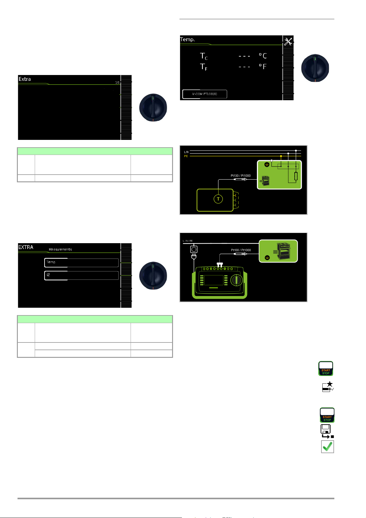
9 Special Functions – EXTRA
EXTRA
EXTRA
EXTRA
Depending on the device configuration, either the QR code for the
Internet link to the operating instructions or the measuring view for
the temperature measurement is displayed.
SECUTEST BASE(10)
Single measurements, rotary switch level: green
Measuring Functions Measurement
Switch
Position
EXTRA None None
QR code: Scanning the QR code allows you to download and read
the current operating instructions from
www.gossenmetrawatt.com, for example at a tablet PC.
Typ e
Measurement with Temperature Sensor
Temperature measurement functions with either a Pt100 or a
Pt1000 temperature sensor – the sensor type is automatically
detected internally.
Schematic Diagram
SECUTEST PRO (feature I01) and SECULIFE ST BASE(25)
Single measurements, rotary switch level: green
Measuring Functions Measurement
Switch
Position
EXTRA Temperature V-COM
Current clamp V-COM
In this case, the additional functions are assigned to the rotary
switch’s EXTRA position.
➭ Select the desired measuring function.
Typ e
Wiring Diagram
Test Sequence with Temperature Sensor
➭ Set the rotary switch to the EXTRA position.
➭ Select the Tem p er at ur e measurement type:
➭ Connect the temperature sensor’s plug to the V-COM sockets
at the test instrument.
➭ Contact the device under test.
➭ Start the test: press the START/STOP key.
➭ The measured values are displayed. The measured
value recording symbol shown at the right appears.
Each time this key is pressed, the currently displayed
measured value is saved to buffer memory.
➭ End the test: press the START/STOP key.
The save symbol appears (floppy disk showing the
number of measured values stored to buffer memory)
and prompts you to save the measured values to an ID
number.
➭ Press the ESC key in order to discard the measured
values stored to buffer memory and acknowledge by
pressing the key shown at the right.
56 GMC-I Messtechnik GmbH
Page 57
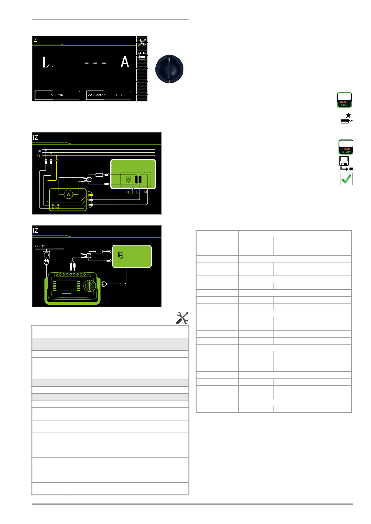
Measurement with Current Clamp Sensor
EXTRA
Current clamp measurement is possible in this case independent
of measuring functions R
at permanently installed devices.
, IPE or IG, e.g. for measuring current
PE
Schematic Diagram
Test Sequence with
Current Clamp Sensor
➭ Set the rotary switch to the EXTRA position.
➭ Select the Current (via clamp) measuring function.
➭ Set the clamp factor at the current clamp sensor.
➭ Clamp factor: Set clamp factor at the test instrument to the
same value as at the current clamp sensor.
➭ Connect the current clamp to the V-COM sockets at the test
instrument.
➭ Enclose the consuming device’s cable with the current clamp
sensor as shown in the schematic diagrams.
➭ Start the test: press the START/STOP key.
➭ The measured values are displayed. The measured
value recording symbol shown at the right appears.
Each time this key is pressed, the currently displayed
measured value is saved to buffer memory.
➭ End the test: press the START/STOP key.
The save symbol appears (floppy disk showing the
number of measured values stored to buffer memory)
and prompts you to save the measured values to an ID
number.
➭ Press the ESC key in order to discard the measured
values stored to buffer memory and acknowledge by
pressing the key shown at the right.
Wiring Diagram
Setting Measuring Parameters for a
Measuring
Parameter
Measurement Type
V – COM Display: A AC Permanent connection
V – COM (with
mains)
Polarity – only for PE-P1 (with mains)
L/N or N/L Selection of polarity for mains voltage to the test socket
Clamp factor
At tester Clamp transformation ratio Suitable clamp
1 V : 1000 A
(1 : 1000)
1 V : 100 A
(1 : 100)
1 V : 10 A
(1 : 10)
1 mV : 1 mA
(1 : 1)
10 mV : 1 mA
(10 : 1)
100 mV : 1 mA
(100 : 1)
1 V : 1 mA
(1000 : 1)
Meaning
Display: A AC: with mains to test
socket, e.g. for measuring protective extra-low voltage at power
packs
1 mV / 1 A WZ12C, Z3512A,
10 mV / 1 A WZ11B, Z3512A,
100 mV / 1 A WZ12B, WZ11B, Z3512A,
1000 mV / 1 A WZ12C, Z3512A,
100 mV : 1 mA SECUTEST CLIP
Current Clamp Sensor
Suitable for
DUT Connection via
Test socket
METRAFLEX 3000
METRAFLEX 3000/300M
METRAFLEX 3000/300M
METRAFLEX 300M
Setting Measuring Range at the Clamp and Parameters at the Test
Instrument
Test Instrument Current Clamp Sensor Test Instrument
Clamp Factor Transformation
Ratio
(switch *)
1000 mV : 1 A 1000 mV : 1 A 1 mA ... 15 A 0 A ... 300 A
1 mV : 1 A 1 mV : 1 A 1 A ... 150 A 1.0 A ... 300 A
100 mV : 1 A 100 mV : 1 A 10 mA ... 100 A 0 A ... 300 A
100 mV : 1 A 100 mV : 1 A 0.5 A ... 20 A 0 A ... 300 A
10 mV : 1 A 10 mV : 1 A 5 A ... 200 A 0 A ... 300 A
1000 mV : 1 A 1000 mV : 1 A 0.001 A ... 1 A 0 A ... 300 A
100 mV : 1 A 100 mV : 1 A 0.01 A ... 10 A 0 A ... 300 A
10 mV : 1 A 10 mV : 1 A 0.1 A ... 100 A 0 A ... 300 A
1 mV : 1 A 1 mV : 1 A 1 A ... 1000 A 0 A ... 300 A
METRAFLEX 3000
100 mV : 1 A 100 mV : 1 A 0.01 A ... 30 A 0 A ... 300 A
10 mV : 1 A 10 mV : 1 A 0.1 A ... 300 A 0 A ... 300 A
1 mV : 1 A 1 mV : 1 A 1 A ... 3000 A 0 A ... 300 A
METRAFLEX 300M
1000 mV : 1 A 1000 mV : 1 A 0.001 A ... 3 A 0 A ... 300 A
100 mV : 1 A 100 mV : 1 A 0.01 A ... 30 A 0 A ... 300 A
10 mV : 1 A 10 mV : 1 A 0.1 A ... 300 A 0 A ... 300 A
100 mV : 1 mA SECUTEST CLIP
100 mV : 1 mA 0.1 ... 25 mA 0.01 mA ... 3.00 A
WZ12C
WZ12B
WZ11B
Z3512A
Measuring
Range
Display Range
with Clamp
GMC-I Messtechnik GmbH 57
Page 58

10 Test Sequences
Note
Status upon shipment (default setting)
Automated test sequences, rotary switch level: orange
Switch
Setting
Preconfigured (freely adjustable) test sequences
A1
A2
A3
A4
A5
A6
A7
A8
AUTO
* Assuming the respective sequence parameter is preset to “on”
** Additional testing of conductive/metallic parts which are not connected to the protective conductor
Auto = automatic detection, see page 61
Standard /
Test Sequence
VDE 0701-0702 Passive Test socket
VDE 0701-0702 Active Auto
VDE 0701-0702-EDV
IEC 62353 (VDE 0751) Passive Test socket BF
IEC 62353 (VDE 0751) Active Auto BF
IEC 60974-4 Active Auto
IEC 60974-4 Active AT16/32-DI
VDE 0701-0702-VLTG
VDE 0701-0702 Auto Auto
Measurement Type
Active
VLTG EL1
Connection
Auto
adap.
Typ e P rot ec -
tion
Freely configurable depending on the selected configuration (protection
category, type of application part)
Category
PC I + PC II **Short-circuit test * – visual inspection * –
PC I + PC II **Short-circuit test * – visual inspection * –
PC I + PC II **Short-circuit test * – visual inspection * –
PC I + PC II **Short-circuit test * – visual inspection * – RPE * – RINS PC I * – RINS PC II+AP * – RINS LN < >
PC I + PC II **Short-circuit test * – visual inspection * – RPE * – RINS PC I * – RINS PC II+AP * – RINS LN < > F *
PC I + PC II **Short-circuit test * – visual inspection * –
PC I + PC II **Visual inspection 1 * –
PCI
PC I + PC II **Short-circuit test * – visual inspection * –
Alt.
** – function test *
**
– IPE LN –
function test *
F * – RINS PE < > F * – IE SK I – IT Alt.
RINS PE < > F * – IE NL PC I – IT NL ** – IA NL BF – IE LN PC I – IT LN ** – IA LN BF – function test *
welding circuit.-PE – RINS PC II
**
– IT S2 LN
** – IT LN
PC II
*
– IPE NL – IT S1 NL
**
– U(0) –
Visual inspection 2 *
Short-circuit test * – visual inspection * –
Alt.
** – function test *
RPE * – RINS PC I * –
IT LN
**
–
function test *
*
** – U(0)/U(R) – function test * –
RPE * – RINS PC I – RINS welding circuit – RINS welding circuit-PE – RINS
**
– IT S2 NL – IT NL
RPE * – RINS PC I * – RINS PC II
RPE * – IPE NL – IT NL
**
– IA BF – function test *
RPE * – RINS PC I – RINS welding circuit – RINS
– IPE NL – IT S1 NL – IT S2 NL – IT NL
**
– IPE LN – IT S1 LN
RPE * – RINS * – continuity (EL1)
RPE * – RINS PC I * –
RINS
PC II
**
** – IPE LN – IT LN
visual inspection 2 *
** – IPE LN – IT S1 LN
**
– IT S2 LN
RINS
PC II
**
**
– IPE Alt. – IT
– IPE NL – IT NL
** –
**
– IT LN
– IPE Alt. – IT
10.1 General
If the same sequence of single tests will be run frequently (one
after the other with subsequent report generation), for example as
specified in the standards, it’s advisable to make use of test
sequences (also called measuring sequences).
Limit values have been entered for test sequences in accordance
with the standards. And thus a go/no-go evaluation takes place
during measurement based on worst-case assessment. If the
momentary measured value is displayed in green, it lies within the
limit values specified in the standard. If the measured value is red,
is does not fulfill the requirements set forth in the standard.
The go/no-go evaluation of the measured values is performed with greater accuracy than the value which
appears at the display, which may lead to the fact that,
due to the missing decimal places, a measured value
which appears at the display may seem to correspond
exactly to the limit value although it’s highlighted in red (as
a limit value violation) due to the places to the right of the
decimal point.
If the measured value is orange, further entries are required after
the test step (e.g. cable length), which are decisive as to whether
or not the test has been passed. Even if the DUT fails just one single measurement, the test sequence is aborted and testing in
accordance with the selected standard is failed.
Automatic test sequences are run in rotary switch positions
AUTO, as well as A1 through A8.
Test sequences A1 through A8 and AUTO are preconfigured at
the factory.
We recommend assigning frequently used test sequences to A1
through A8, and conducting special sequences for which parameters often need to be adjusted in the AUTO switch position.
The measurements are evaluated automatically by the test instrument. Evaluation is based on the worst-case and, depending on
settings, in consideration of measuring uncertainty.
Specifications for the test sequences can be entered to the test
instrument in two different ways:
• SETUP switch position: general settings can be entered which
apply to all test sequences (regardless of the respectively
selected standard).
• Switch positions AUTO and A1 to A8: classification and sequence
parameters can be entered which only apply to the selected
switch position.
Test Sequences in the AUTO Switch Position
The following test sequences are included as a standard feature
with the SECUTEST BASE(10) and the SECULIFE ST BASE(25) in rotary
switch positions AUTO and A1 to A8:
• DIN VDE 0701-0702
Periodic testing and testing after repair and modification of
electrical equipment
• IEC 62353
Medical electrical equipment – Recurrent test and test after
repair of medical electrical equipment (applied parts with test
probe P1)
• IEC 60974-4
Arc welding equipment – Part 4: Periodic inspection and testing (voltage measurement with test probe P1 without electrical
isolation) One pole of the voltage to be measured must be
connected to PE at the mains.
The individual sequences are selected with the softkeys.
User-Defined Test Sequences
Up to 24 * customer-specific (user-defined) test sequences can
be saved to the test instrument and assigned to rotary switch
positions AUTO and A1 to A8. The sequences are created at the
PC with the help of IZYTRONIQ software (up to firmware 1.7.2:
Sequence Designer software).
The measurements and parameters available in your SECUTEST
version are loaded from the test instrument and made available in
the PC software for this purpose. Finally, the created test
sequence can be loaded directly to the SECUTEST... (prerequisite: database extension, feature KB01, “Z853R – SECUTEST
DB+”) and saved to the computer as an XML file. As a rule, customer-specific (user-defined) test sequences are identified with a
preceding asterisk (*) in the SECUTEST user interface.
* As of firmware version 2.0, a tota l of 24 user-defined test sequences can be loaded
to the test instrument with feature KB01, “Z853R – SECUTEST DB+”.
58 GMC-I Messtechnik GmbH
Page 59

10.2 User-Defined Test Sequences / Remote Control
Note
Attention!
!
Attention!
!
Note
Note
Note
SETUP
(only with feature KB01, “Z853R – SECUTEST DB+”)
10.2.1 General
When creating user-defined test sequences, the author of the test
sequence can define and configure individual test steps himself,
and specify the order in which they’re run.
With the help of IZYTRONIQ
sequences can be created at the PC and transferred to the test
instrument via a USB port.
Up to 1200 test steps can be distributed to as many as
24 test sequences and saved to memory at the test
instrument.
Similar options are available to the user when the test instrument
is remote controlled (e.g. via IZYTRONIQ IZY remote test
sequences).
Some of the test steps necessitate advance testing in the form of
inspections or test instructions, for example so that the inspector
has enough time to contact the respective location with the probe
at the point in time of test execution, or to set the DUT to the
appropriate state.
If user-created test sequences are created and/or used, or in the
case of remote control of the test instrument, the creator of the
test sequences or the user/inspector assumes responsibility for
standards-compliant test steps and execution of advance tests in
the correct order.
If you change or shorten the default test sequences
for the respective standards, the danger exists that they
will no longer be compliant and will thus become invalid
as substantiation of operating safety in accordance with
DGUV regulation 3 or BetrSichV, or will no longer fulfil
these standards.
PC software (as of firmware 2.1.1), test
10.2.2 Testing of Probe Connection P1 and Probe Fuse P1
If probe P1 is used in a test sequence, a “Probe Test” step with
“Probe: Probe Connection P1” must be included in the respective
test sequence. Background: In addition to assuring that a probe
is connected to probe connection P1, the probe test at connection P1 also determines whether or not the probe’s fuse link is
intact.
If the fuse at test probe P1 is defective, all subsequent
measurements using this measuring path are incorrectly
evaluated as good!
Automatic Measurements (1/3)
❑ At the End of the Sequence
At the end of a sequence, either the save symbol appears in
order to prompt storage (“memory screen” parameter), or the
results list (“results list” parameter) is displayed.
❑ Considering Measuring Uncertainty
If Yes is selected, measuring uncertainty is taken into consideration when the measurement results are displayed. The final
result which appears at the display is downgraded by an
amount equal to measuring uncertainty.
❑ Auto Measuring Point
If Yes is selected, the test instrument detects whether or not
the protective conductor is contacted with the probe during
the protective conductor resistance measurement of an automatic test sequence and automatically starts recording a new
measuring point. Statuses are indicated by various, continuous acoustic signals. The protective conductor test can thus
be conducted without using the keys on the instrument.
The “Auto Measuring Point” function is only activated
during test steps of the “multiple measurement” type. If
you want to use this function ...
– In the case of integrated test sequences: Make sure
that the “multiple measurement” test parameter
(see page 54) is selected for the RPE test step.
– In the case of user-defined test sequences (only with
database extension, feature KB01, “Z853R –
SECUTEST DB+”): make sure that the RPE test step
has been entered to the sequence as a “multiple
measurement”.
Automatic Measurements (2/3)
❑ Initial Window Style
Selection can be made here between a tree view and a detail
view for the first page of the test sequence (see section 10.4).
❑ Limit Value Mode
If you want to use only the limit values specified in the standards to evaluate the measurements, set the parameter to
Normal.
When set to Expert, the LIMIT softkey appears next to the
“measurement failed” popup if the measurement has not been
passed. This key makes it possible to enter a user-defined
limit value (as a rule a limit value specified by the manufacturer
which deviates from the standard), in order to allow the test to
be passed under these new conditions.
Entry of a user defined limit value is not possible if “Continue” is selected for the “Limit Violation” option.
10.3 General Settings (Setup: auto measurements parameter)
The following settings can be entered for all test sequences in the
SETUP switch position on menu page 1/3 under the auto measurements parameter (see section 4.3):
GMC-I Messtechnik GmbH 59
❑ Limit Value Violation (only with feature KD01, “Z853S – SECUTEST
DB COMFORT”)
With its “Try Again” operating mode, the test instrument makes
it possible to immediately restart the failed test step and
repeat the measurement in the event that a limit value is violated.
In the “Continue” mode, the test instrument doesn’t terminate
the test sequence in the event of a limit value of violation, and
instead continues testing despite any individual steps which
have failed.
If a limit value violation occurs during the test sequence,
the respective test step designation appears in red in the
header for all following test steps, so that it’s already
Page 60

made apparent during the test sequence that a limit value
Note
violation has occurred during one of the previous test
steps, and that the device under test will not pass testing.
Automatic Measurements (3/3)
❑ Measuring sequences (no longer in the “Culture” menu as of firmware
V1.6.0)
The following standards can be selected here:
VDE, OVE (Dutch version: NEN)
The instrument is restarted if the setting for “Measuring
Sequences” has been changed and the “Auto Measurements”
menu is exited.
The test instrument must be restarted after changing the
measuring sequences.
Database structure and content remain unchanged.
❑ Autostore (feature KD01, “Z853S – SECUTEST DB COMFORT”)
If this function is activated (“on”), the test results for the automatic
test sequence are immediately saved under the test object (=
device or ME device (medical electric device)) which is currently
selected in the database.
If you haven’t yet selected a test object in memory management
(MEM key), a message appears informing you that automatic
storage of the current test is not possible.
You’re prompted to enter an object ID via the scanner or the softkeys, or to select one from the database (MEM key). In this case
you have to save the test manually to the database via the “Save”
softkey.
❑ Skip steps
Here you can configure whether or not the user is allowed to skip
test steps during a test sequence (“on”).
This does not apply to inspection test steps that can be omitted
(which have no relevance with regard to the standard)!
Meaning of Symbols in the User Interface – Test Sequence
Sym-
Softkey Variants, Test Sequence
bol
Test for Protection Category I Devices
Exposed, conductive parts are connected to the protec-
tive conductor so that they are not charged with voltage if
the basic insulation should fail.
Test for Protection Category II Devices
These devices are equipped with double insulation or rein-
forced insulation.
Test for Protection Category III Devices
These devices are supplied with safety extra-low voltage
(SELV). Beyond this, no voltages are generated which
exceed SELV.
Type B applied parts (body)
Sym-
Softkey Variants, Test Sequence
bol
Stop test sequence
– Repeat inspection (if it has been failed).
– Repeat test step
– Skip inspection test step
– Skip individual tests within the test sequence
This option can be enabled for the user in SETUP under
“Auto Measurements”.
Start evaluation – record measured value. Each time this
softkey is pressed, an additional measured value is saved
and the number is increased by one.
Start evaluation sequence during a
The number blinks.
Record measured value during the evaluation sequence of a
continuous measurement.
Repeat measured value recording
Delete measured value
Display measured values
Display details from the results list
Hide details from the results list
The ID number to which the measurement(s) will be stored
can be entered here.
Valid measured values have been obtained for a test
sequence. This measurement can be saved.
Save measurement data as (with display of directory path
/ ID or new entry of an ID other than the preselected one)
Transmit measurement data to a PC, e.g. in order to save
them to IZYTRONIQ report generating software (push-print
function) – refer to IZYTRONIQ online help for a description
Read-out of a complete test report at the end of a test
sequence
Read-out of a summarized test report at the end of a test
sequence
Read-out of all failed test steps instead of a test report at
the end of the test sequence
continuous measurement
.
Type BF applied parts (body float)
Type CF applied parts (cardiac float)
Configure sequence parameters (see page 64)
Set classification parameters
Assess visual inspection or function test with OK
or not OK (toggle key)
Enter a comment, e.g. for the visual inspection or function
test
Continue test, next test step in the test sequence
Stop continuous measurement, next test in test sequence
Accept changed parameter,
return to memory view
60 GMC-I Messtechnik GmbH
Page 61

10.4 Selecting and Configuring a Test Sequence
A1
Standard / Test Sequence
Connection Type Protection Category
Cl. parameter
Measurement Type
Status line
Sequence Parameter
Tree view *
A1
Connection Type
Protection Category
Cl. parameter
Measurement Type
Status line
Sequence Parameter
Applied parts
Detail view *
Standard / Test Sequence
Sample: Initial Page of a Test Sequence – Tree View
Conveniently Changing Classification Parameters
(optional feature E01, touchscreen)
➭ The corresponding selection menu appears after touch click-
ing (briefly tapping) the respective classification parameters
window.
➭ The display is automatically returned to the start menu after
selecting the desired parameter.
Sample: Initial Page of a Test Sequence – Detail View and Applied
* SETUP switch position:
Setup Menu 1/3 > Auto Measurements > 2/2 > Initial Window Style:
Tree or Detail View
Test instruments with feature E01 (touchscreen)
The display can be switched back and forth between the “tree
view” and the “detail view” (see above) via “Touch Click”, i.e. by
briefly tapping within the bottom frame.
Classification Parameter – Automatic Detection
If the settings for certain classification parameters are automatically detected by the test instrument, this is indicated in each case by
an orange frame (as of firmware V1.3.0; here: test socket connection
type and protection category I). Descriptions of these parameters are
listed in the following tables relative to the respective switch positions.
Classification Parameter – VDE 0701-0702
Parameter Setting Options / Meaning
1/2
Standard
Protection class
Connection type
1, 2
1, 2
2/2
Measurement type (MA) 1 Passive
Auto-detection Connection & PC & MT
1
These parameters must be entered manually if they’re not automatically detected,
or if they’re detected incorrectly.
2
The limit value for protective conductor resistance is determined on the basis of
length and cross-section. Data remain in memory until a new entry is made.
VDE 0701-0702
VDE 0701-0702-EDV, see following table
VDE 0701-0702-VLTG, see table below
VDE 0701-0702-PRCD, see table below
IEC 62353, see table below
IEC 60974-4, see table below
PCI, PCII, PCI+II, PCI+III, PCII+III, PCI+II+III
Test socket
Permanent connection
Adapter: AT16/32-DI adapter
Adapter: VL2E
Adapter: AT3-Adapter (feature I01)
Permanent connection: P1+P2 (only with feature H01)
Active
Connection & PC
Connection & MT
Connection only
PC & measurement type
Protection class only (PC)
Measurement type only (MT)
Disabled: No auto-detection:
all classification parameters such as connection, protection
category and measurement type must be entered manually.
GMC-I Messtechnik GmbH 61
Automatic detection active for protection class
When connecting or disconnecting a DUT, the protection class can be changed without prior authorization.
Automatic detection inactive for protection class
The test instrument retains the selected safety class
setting when a DUT is connected or disconnected.
Page 62

Classification Parameter – VDE 0701-0702-EDV
Note
Note
Note
Classification Parameter – VDE 0701-0702-PRCD
Parameter Setting Options / Meaning
1/2
Standard VDE 0701-0702, see table below
Protection class
Connection type
1, 2
1, 2
VDE 0701-0702-EDV
VDE 0701-0702-VLTG, see table below
VDE 0701-0702-PRCD, see table below
IEC 62353, see table below
IEC 60974-4, see table below
PCI, PCII, PCI+II, PCI+III, PCII+III, PCI+II+III
Test socket
Permanent connection
Adapter: AT16/32
Adapter: AT3-Adapter (feature I01)
2/2
Measurement type (MA) 1 Active
Auto-detection Connection & PC & MT
1
These parameters must be entered manually if they’re not automatically detected,
or if they’re detected incorrectly.
2
The limit value for protective conductor resistance is determined on the basis of
length and cross-section. Data remain in memory until a new entry is made.
Connection & PC
Connection & MT
Connection only
PC & measurement type
Protection class only (PC)
Measurement type only (MT)
Disabled: No auto-detection:
all classification parameters such as connection, protection
category and measurement type must be entered manually.
Classification Parameter – VDE 0701-0702-VLTG
Parameter Setting Options / Meaning
1/2
Standard VDE 0701-0702, see table below
Protection class
Connection type
1, 2
1, 2
2/2
Measurement type (MA) 1VLTG
Auto-detection Connection & PC & MT
1
These parameters must be entered manually if they’re not automatically detected,
or if they’re detected incorrectly.
2
The limit value for protective conductor resistance is determined on the basis of
length and cross-section (length only in the case of EL1). Data remain in memory
until a new entry is made.
VDE 0701-0702-EDV, see previous table
VDE 0701-0702-VLTG
VDE 0701-0702-PRCD, see following table
IEC 62353, see table below
IEC 60974-4, see table below
PCI
Test socket
Adapter: AT3-IIIE
Adapter: EL1 adapter
Adapter: VL2E adapter
2
Connection & PC
Connection & MT
Connection only
PC & measurement type
Protection class only (PC)
Measurement type only (MT)
Disabled: No auto-detection:
all classification parameters such as connection, protection
category and measurement type must be entered manually.
Parameter Setting Options / Meaning
1/2
Standard VDE 0701-0702, see table below
Protection class
Connection type
1, 2
1, 2
VDE 0701-0702-EDV, see table above
VDE 0701-0702-VLTG, see previous table
VDE 0701-0702-PRCD
IEC 62353, see following table
IEC 60974-4, see table below
PCI, PCI+II
Test socket
2
2/2
Measurement type (MA) 1PRCD
PRCD type
Auto-detection Connection & PC & MT
1
2
3
New classification parameter “PRCD type” (as of firmware V1.7.0)
3
These parameters must be entered manually if they’re not automatically detected,
or if they’re detected incorrectly.
The limit value for protective conductor resistance is determined on the basis of
length and cross-section. Data remain in memory until a new entry is made.
3
PRCD (standard)
PRCD (SPE)
PRCD-S (SPE)
PRCD-K (SPE)
Connection & PC
Connection & MT
Connection only
PC & measurement type
Protection class only (PC)
Measurement type only (MT)
Disabled: No auto-detection:
all classification parameters such as connection, protection
category and measurement type must be entered manually.
(only displayed if “Standard
VDE 0701-0702-PRCD” parameter is selected):
– PRCD (standard):
For the testing of simple circuit breaker safety adapters in
which the protective conductor is permanently connected.
– PRCD (SPE):
(SPE = switched protective earth) for testing PRCDs in which
the protective conductor is only connected in switched-on
condition.
– PRCD-S (SPE):
For testing type PRCD-S circuit breaker safety adapters.
– PRCD-K (SPE):
For testing type PRCD-K circuit breaker safety adapters.
The standard or standard variant associated with the
respective selector switch position corresponds to the
default setting.
Ax means that standard variant VDE 0701-0702-PRCD
can be selected in each of the preset switch positions.
For more information on the testing of single-phase and
3-phase type S and K PRCDs by simulating faults see
PROFITEST PRCD test adapter on our website.
Testing of PRCDs (test sequences and time to trip) is only
possible for the DUTs with a nominal voltage of 230 V.
62 GMC-I Messtechnik GmbH
Page 63

Classification Parameter – IEC 62353
Note
Classification Parameter – IEC 60974-4
Parameter Setting Options / Meaning
1/2
Standard VDE 0701-0702, see table below
Protection class
Connection type
1
1
VDE 0701-0702-EDV, see table above
VDE 0701-0702-VLTG, see table above
VDE 0701-0702-PRCD, see previous table
IEC 62353
IEC 60974-4, see following table
PCI, PCII or PCI+II
Test socket
Permanent connection
Adapter: AT16/32-DI adap.
Adapter: AT3-Adapter
Permanent connection: P1+P2 (only with feature H01)
2/2
Measurement type (MA) 1Passive
Applied parts Applied parts: none, B, BF, CF or combinations
Auto-detection Connection & PC & MT
1
These parameters must be entered manually if they’re not automatically detected,
or if they’re detected incorrectly.
Active
Type B (body): Devices of this type are suitable for both
internal and external patient applications, except for use
in direct proximity to the heart.
The following protection categories are permissible:
I, II, III or devices with internal electrical power supply.
Type BF (body float): Same as type B, but with type F insulated applied parts.
Type CF (cardiac float) Devices of this type are suitable
for use directly at the heart. The applied part may not be
grounded.
The following protection categories are permissible:
I, II or devices with internal electrical power supply.
Connection & PC
Connection & MT
Connection only
PC & measurement type
Protection class only (PC)
Measurement type only (MT)
Disabled: No auto-detection:
all classification parameters such as connection, protection
category and measurement type must be entered manually.
Parameter Setting Options / Meaning
1/2
Standard VDE 0701-0702, see table below
Protection class
Connection type
1
1
VDE 0701-0702-EDV, see table above
VDE 0701-0702-VLTG, see table above
VDE 0701-0702-PRCD, see table above
IEC 62353, see previous table
IEC 60974-4
PCI, PCII or PCI+II
Test socket
Permanent connection
Adapter: AT16/32-DI adap.
Adapter: AT3-Adapter
2/2
Measurement type (MA) 1Active
Voltage, rating plate Voltage from rating plate, U(R) RMS
(RMS limit value, variably adjustable)
or open-circuit voltage U0 DC (limit value = 113 V DC)
Auto-detection Connection & PC & MT
Connection & PC
Connection & MT
Connection only
PC & measurement type
Protection class only (PC)
Measurement type only (MT)
Disabled: No auto-detection:
all classification parameters such as connection, protection
category and measurement type must be entered manually.
1
These parameters must be entered manually if they’re not automatically detected,
or if they’re detected incorrectly.
The limit values in the test instrument are set in accordance with IEC 60974-4:2016 status as of firmware version 2.1.0.
GMC-I Messtechnik GmbH 63
Page 64

Sequence Parameter (as of firmware V1.3.0)
The default test sequences can be adapted to your application or test standard via the sequence parameter. The entered
sequence parameter settings are only valid for the currently
selected switch position (A1 to A8 or AUTO) and are retained until
they are changed. Not all of the parameters are relevant, depending on the selected DUT classification (protection category etc.).
Sequence Parameter Meaning
Visual inspection (1) Visual inspection (standard):
Visual inspection 2
(IEC 60974-4)
Function test Function test:
Protective conductor resistance test
RPE Protective conductor resistance test:
RPE IP Protective conductor resistance at test socket:
RPE IP permanent
connection
RPE as Protective conductor resistance test:
RPE measurement
duration
Insulation resistance test
RINS PC I Insulation resistance tests for PCI:
RINS PC II Insulation resistance tests for PCII:
RINS PC I and II
(VDE 0701-0702)
(IEC 60974-4)
RINS at AP Insulation resistance tests at application parts:
Measurement duration
RINS probe
Measurement duration
RINS AP
RINS pri./sec.
(VDE 0701-0702)
(IEC 60974-4)
RINS PC II as
(VDE 0701-0702)
(IEC 60974-4)
Measurement duration
RINS PC II
RINS sec./PE
(VDE 0701-0702)
(IEC 60974-4)
Leakage current tests
on: activate
off: deactivate
Visual inspection, function test, welding units
on: activate
off: deactivate
on: activate
off: deactivate
on: activate
off: deactivate
Select test current IP: ±200 mA= / 200 mA~ /
Feature G01: 10 A~ / feature G02: 25 A~
Protective conductor resistance with permanent connection:
Select test current IP: ±200 mA= / 200 mA~ /
Feature G01: 10 A~ / feature G02: 25 A~
Execute as individual or multiple measurement.
Multiple measurement: Repeat testing of various conductive parts as often as desired, in the event that it’s not
clear as to whether or not all accessible, conductive parts
are connected to each other or to the protective conductor.
Protective conductor resistance test:
A measurement duration within a range of 0 to 60 seconds can be entered here.
on: activate
off: deactivate
on: activate
off: deactivate
Insulation resistance tests for PCI and II:
on: activate
off: deactivate
on: activate
off: deactivate
Insulation resistance test via probe:
A measurement duration within a range of 0 to 60 seconds can be entered here. Default setting: 3 s
Insulation resistance tests at application parts:
A measurement duration within a range of 0 to 60 seconds can be entered here. Default setting: 3 s
Insulation resistance test between the primary and secondary sides of PCIII DUTs
on: activate
off: deactivate
Insulation resistance test:
Execute as individual or multiple measurement.
Multiple measurement: Insulation resistance is measured
between short-circuited mains terminals (L-N) and accessible, conductive parts which can be contacted with test
probe P1 and are not connected to the housing, repeat as
often as desired.
Insulation resistance test:
A measurement duration within a range of 0 to 60 seconds can be entered here. Default setting: 3 s
Insulation resistance test between the secondary side and
PE of PCIII DUTs:
on: activate
off: deactivate
Sequence Parameter Meaning
Reverse polarity Leakage current tests:
IPE
(VDE 0701-0702)
(IEC 60974-4)
IPE measurement type
(active)
(VDE 0701-0702)
IPE measurement duration
(VDE 0701-0702)
(IEC 60974-4)
IE
(IEC 62353)
IE measurement type
(active)
(IEC 62353)
IE measurement duration
(IEC 62353)
IT measurement type
(active)
(VDE 0701-0702)
IT
(IEC 62353)
(IEC 60601)
IT as
(IEC 62353)
IT measurement duration
(IEC 62353)
IT welding circuit
(IEC 60974-4)
IT PC II as
(IEC 60974-4)
IT PC II measurement
duration
(IEC 60974-4)
IP AC
(IEC 60601)
IP DC
(IEC 60601)
IP measurement duration
(IEC 60601)
Test conditions / fault conditions
IA
(IEC 62353)
Measurement duration IA
AP
(IEC 62353)
Connection and fuse tests
Short-circuit test L-N Short-circuit test between L and N
Short-circuit test LN-PE Short-circuit test between LN and PE1
Display test instructions
Fuse test Testing the fuses:
On:
Measurements are conducted with both polarities.
Off: Measurement is only conducted with one/momentary polarity.
Protective conductor current:
on: activate
off: deactivate
Protective conductor current test (mains to test socket):
Measuring method: Direct or differential
Protective conductor current test:
A measurement duration within a range of 0 to 60 seconds can be entered here. Default setting: 3 s
Device leakage current test:
on: activate
off: deactivate
Device leakage current test
Measuring method: Direct or differential
Device leakage current test:
A measurement duration within a range of 0 to 60 seconds can be entered here. Default setting: 3 s
Touch current test (mains to test socket):
Measuring method: Direct P1 or differential P1
The “Differential P1” method is only advisable in this case
if the device under test has ground connections which
cannot be disconnected for testing.
Touch current test
on: activate
off: deactivate
Touch current test:
Execute as individual or multiple measurement.
Multiple measurement: Various accessible, conductive
parts are contacted with test probe P1 in order to measure current flowing to the protective conductor via the
probe – repeat as often as desired.
Touch current test:
A measurement duration within a range of 0 to 60 seconds can be entered here. Default setting: 3 s
Touch current test at welding circuit:
on: activate
off: deactivate
Touch current test at welding circuit:
Execute as individual or multiple measurement.
Touch current test at welding circuit:
A measurement duration within a range of 0 to 60 seconds can be entered here. Default setting: 3 s
Patient leakage current AC:
on: activate
off: deactivate
Patient leakage current DC:
on: activate
off: deactivate
Patient leakage current:
A measurement duration within a range of 0 to 60 seconds can be entered here. Default setting: 3 s
Leakage current test at application part:
on: activate
off: deactivate
Leakage current test at application part:
A measurement duration within a range of 0 to 60 seconds can be entered here. Default setting: 3 s
on: activate
off: deactivate
on: activate
off: deactivate
Test instructions which are not necessarily required for experienced inspectors
on: activate
off: deactivate
Mains fuses, test probe fuse P1,
application part fuses
(mains to test socket):
1
1
64 GMC-I Messtechnik GmbH
Page 65
Sequence Parameter Meaning
Other parameters
Open-circuit voltage
(IEC 60974-4)
Supply voltage PC III
(VDE 0701-0702)
Testing of extension cords – additional parameters (VDE 0701-0702-VLTG)
Continuity test Testing of conductors (L, N, PE) for continuity with the
Testing of PRCDs – additional parameters (VDE 0701-0702-PRCD)
RPE IP (standard PRCD) Protective conductor resistance test with standard
Varistor test PRCD-K Varistor test at type K PRCDs:
Sensor surface test Testing of the sensor surface of the PRCD:
Man. tripping test Manual tripping of the PRCD:
Time to trip Tripping of the PRCD after xx seconds:
Open-circuit voltage at welding unit
on: activate
off: deactivate
Supply voltage measurement
(with PCIII DUTs, for measurement type “Active” only)
on: activate
off: deactivate
help of the EL1/VL2E/AT3-IIIE adapter
on: activate
off: deactivate
PRCDs: Select test current IP: ±200 mA= / 200 mA~ /
Feature G01: 10 A~ / feature G02: 25 A~
on: activate
off: deactivate
on: activate
off: deactivate
on: activate
off: deactivate
on: activate
off: deactivate
❑ Suppressing Test Steps
Depending on the selected test standard, some of the following
test steps can be suppressed:
Parameter Suppressible test steps
Visual inspection (1) Visual inspection, standard
Visual inspection 2 Visual inspection, function test, welding units
Function test Function test
RPE Protective conductor resistance test
RINS PCI+II Insulation resistance tests for PCI and PCII
RINS pri./sec. Insulation resistance test between the primary and sec-
RINS sec./PE Insulation resistance test between the secondary side and
RINS BF/CF
(IEC 62353)
RINS welding circuit
(IEC 60974-4)
Reverse polarity All leakage current measurements with reversed polarity
IPE measurement type
(active)
IT
IT welding circuit
Display test instructions
Short-circuit test L-N Short-circuit test between L and N
Short-circuit test LN-PE Short-circuit test between LN and PE1
Open-circuit voltage
(IEC 60974-4)
Continuity Test
(VLTG test only)
PCIII supply voltage Supply voltage measurement (with PCIII DUTs, for mea-
1
Before switching line voltage to the device under test, a short-circuit test is conducted regardless of this setting.
ondary sides of PCIII DUTs
PE of PCIII DUTs
Insulation resistance tests at BF/CF application parts
RINS tests between the primary side and the welding output, as well as between PE and the welding output
Protective conductor current test
Touch current test
Touch current test at welding circuit
Test instructions which are not necessarily required for experi-
enced inspectors
1
1
Open-circuit voltage at welding unit
Continuity test with EL1/VL2E/AT3-IIIE adapter
surement type “Active” only)
❑ Setting Measuring Parameters for Individual Test Steps
Depending on the selected test standard, some of the following
test steps can be selected:
Parameter Meaning
RPE IP Select test circuit for protective conductor resistance test:
200 mA AC, ±200 mA DC, 10 A AC
IPE measurement type
(active)
IE measurement type
(active)
Set measurement type of the protective conductor current
measurement for the active device test (differential/direct)
Set measurement type of the device leakage current measurement for the active device test (differential/direct)
(IEC 62353)
1
SECUTEST BASE10/PRO (feature G01)
2
SECULIFE ST BASE25 (feature G02)
❑
Select between single and multiple measurement for individual test steps
Parameter
Meaning
1
or 25 A AC
2
(as of FW1.5.0)
RPE as
Parameter
Switch the “protective conductor resistance” test step back
and forth between multiple and single measurement
Meaning
(as of FW1.8.0)
RINS PC II as Switch back and forth between multiple and individual
IT as switch back and forth between multiple and individual
IT PC II as (IEC 60974 only) switch back and forth between multiple
measurement for the insulation resistance measurement
at PC II parts (measurements at application parts and
welding outputs are not affected)
measurement for the touch current measurement
and individual measurement for touch current measurement at PC II parts
GMC-I Messtechnik GmbH 65
Page 66

❑ Setting Measurement Duration for Individual Test Steps
Testing time for the respective measurement can be influenced
with these parameters. If a test step for a single measurement is
involved, the entire test step has a duration of the time entered in
seconds. If a test step for a multiple measurement is involved, the
measurement duration for each measuring point is influenced.
If 0 seconds is selected, continuous measurement is conducted
which can only be ended by the inspector by pressing a key.
Parameter
Meaning
(as of FW1.5.0)
RPE measurement
1
duration
IPE measurement duration Set testing time for the protective conductor current mea-
IE measurement duration Set testing time for the device leakage current measure-
1
In the case of test sequence VDE 0701-0702-PRCD with a setting of
“PRCD type: PRCD (SPE)”, measurement duration cannot be influenced.
The measurement duration which has been set here only affects the RPE measurement with PRCD types “PRCD (standard)” and “PRCD-S (SPE)”.
Set testing time for the protective conductor resistance
measurement (0 to 60 seconds)
surement (0 to 60 seconds)
ment (0 to 60 seconds)
Parameter
Meaning
(as of FW1.8.0)
IT measurement duration Set testing time for touch current measurement
IT PC II measurement
duration
RINS PC II measurement
duration
(0 to 60 seconds)
(for IEC 60974 only) Set testing time for touch current
measurement at PC II parts (with the exception of welding
outputs) (0 to 60 seconds)
Set testing time for RINS measurements and PC II parts
(0 to 60 seconds)
66 GMC-I Messtechnik GmbH
Page 67
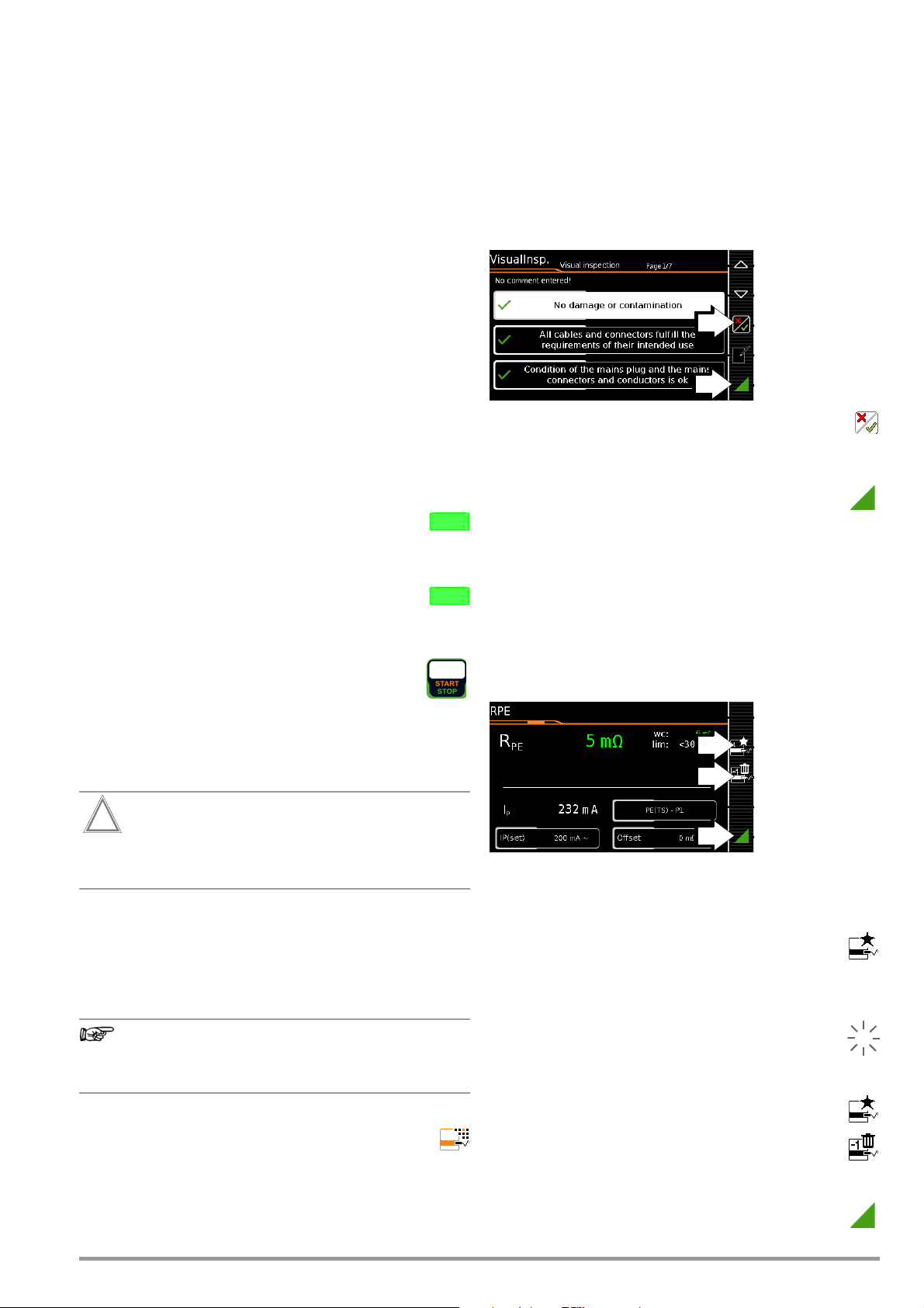
10.5 Connecting the DUT
Attention!
!
Note
MEM
ESC
0
1
1
➭ Connect the DUT to the test instrument in accordance with
the selected test sequence.
– Test socket
– Permanent Connection
– Adapter
Note concerning use of the AT3-IIIE test adapter
Please note that polarity reversal with the help of the utilized test
instrument is not active when the AT3-IIIE adapter is used for testing single-phase DUTs (socket 3 / earthing contact). In this case,
all leakage current measurements must be performed manually
with the plug in both directions.
Switch settings A1 ... A7, AUTO
Connection depends on the type of DUT (see the respective connection type in the classification parameters tables).
Switch position A8
For testing extension cords in accordance with standards: connection to the test socket via the following adapter:
– EL1: For single-phase extension cords
– VL2E:
For single and 3-phase extension cords
10.6 Selecting a Test Object
➭ If no DUT has been selected in the initial display, enter its ID
number (for example using a barcode scanner) after selecting
ID.
Alternatively, activate
➭
key.
➭ Select the DUT for the test sequence with the scroll keys.
➭ Return to the measuring view by pressing the ESC key.
the database view with the MEM
10.7 Checking Connection and Starting the Test Sequence
➭ Trigger the connection test and the test sequence
by pressing the START key.
The following checks are run automatically before the
test sequence is started:
•Probe Test
(as to whether or not to test probe P1 is connected
P1 is intact
)
and use link
• Connection test *: Checks whether the DUT is connected to
the test socket. In the case of protection category I: whether
or not the two protective conductor terminals are short-circuited.
*Applies to
M7050
with feature B00 and B09
10.8 Executing and Evaluating Test Steps
Manual evaluation of visual inspection
(prerequisite: “visual inspection” sequence parameter is preset to
“on”.)
➭ Evaluate the visual inspection.
➭ If you mark even one visual inspection as not passed
with the key shown at the right, the sequence is aborted and
the test is evaluated as not passed.
➭ Resume the test sequence.
Connecting Line Voltage
Connecting line voltage to the test socket at the test instrument
and performance of a function test are only permissible if the DUT
has already passed the safety test (protective conductor resistance and insulation resistance measurements)!
Do not start measurements at your test instrument unless it’s in
plain view. Do not connect line voltage to the test socket of your
test instrument before the surrounding area has been secured.
Test Steps with Manual Evaluation (e.g. RPE)
If the fuse at test probe P1 is defective, all subsequent
measurements using this measuring path are incorrectly
evaluated as good!
• Insulation test (whether or not the DUT is set up in a well-insulated fashion)
• On test and short-circuit test
(prerequisite: “short-circuit test L-N” sequence parameter is
preset to “on”.
In order to be able to detect a short-circuit at the DUT, testing
is conducted between L and N, as well as LN and PE.
If you deselect important test steps under sequence parameter (set to off), the test sequence might not fulfill the requirements stipulated by the standard any more.
If you have set the “
respective test sequence to “Always accept” and the “
detection of
gering Start), the following additional checks will be run
before the test sequence is started:
• Protection category detection for DUTs with protective conductor
GMC-I Messtechnik GmbH 67
” parameter to “
*
Detected classification
Connection and PC
” parameter for the
Auto-
” (before trig-
➭ Observe instructions which appear at the display, e.g.
prompting to contact parts with test probe P1.
If the measured value appears green at the display, it lies within
the limits specified by the standard.
➭ The measured value recording symbol appears in the
softkey bar. The 0 indicates that no measured values
have thus far been saved to buffer memory.
➭ Each time this key is pressed, the measuring or evaluation
procedure is restarted.
➭ Initially, the digit blinks (here a 1 without symbol) until
the measured value settles in. The evaluation cycle is
visualized as follows: the progress bar starts at the lefthand edge of the display and moves to the right. When
it reaches the rightmost position, evaluation has been
completed and the symbol shown at the right appears
with the current number.
➭ Depending on whether you want to delete the last
value saved to the clipboard or all values, press the
symbol with the wastebasket shown at the right an appropriate number of times.
➭ Proceed to the next measurement by pressing the key
shown at the right.
Page 68
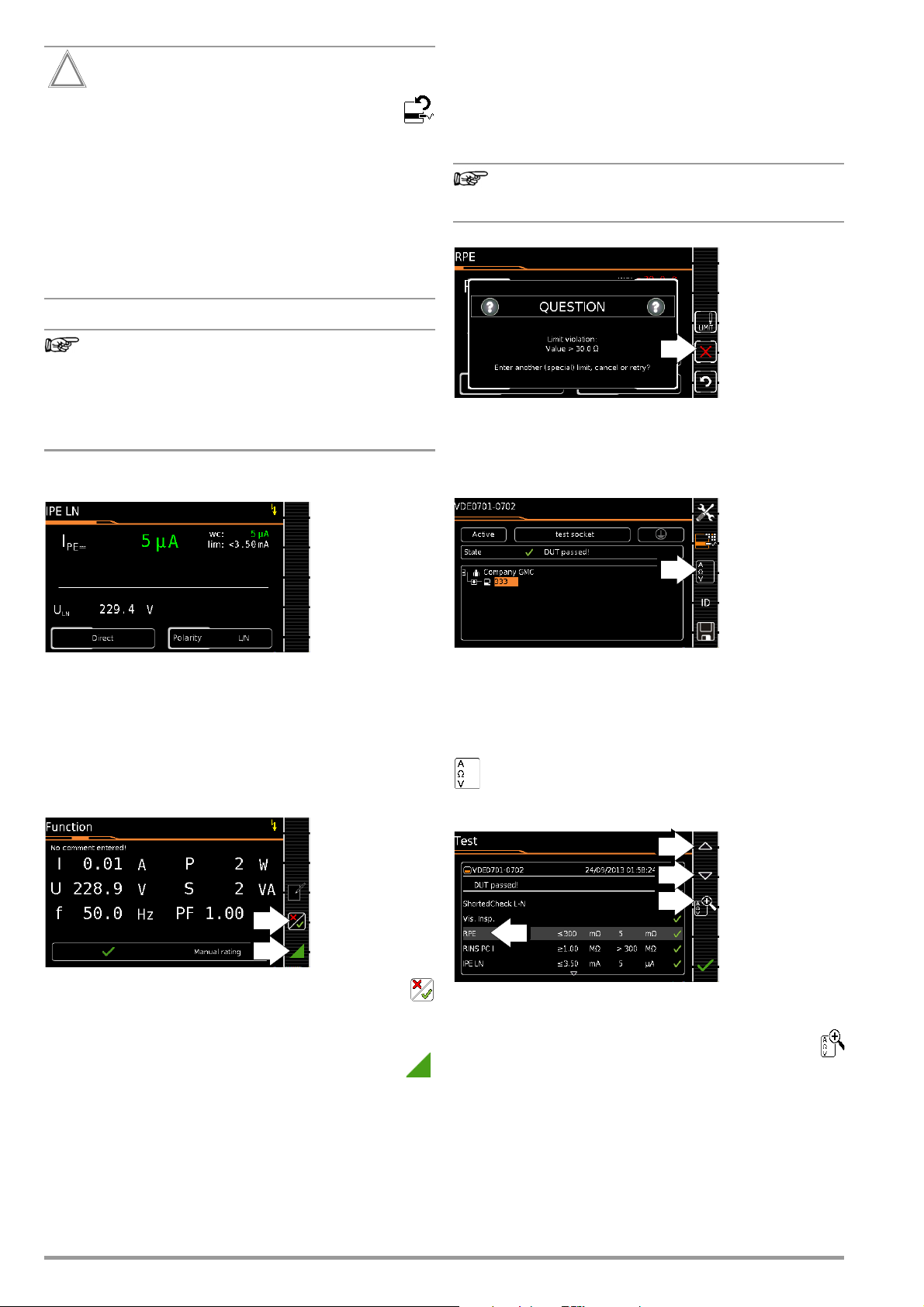
Attention!
!
Limit value violation
Note
Note
If the measured value appears red at the display,
a limit value has been violated. If you nevertheless
start the evaluation procedure, an error message appears. You have the option of repeating the evaluation
procedure.
If Continue is selected for the “Limit Violation” option in
SETUP (Auto Measurements 2/3), the test instrument
continues testing despite any limit value violations. In this
case, the device under test is operated with line voltage
despite any insulation faults or the like. Make sure that
the device under test is secured, in particular against
contact during the testing process.
Regarding the test sequence in switch position A6/A7:
Section 5.2 of DIN EN 60974-4expressly stipulates that
the cables have to be bent and twisted over their entire
length during the measurement, in particular in proximity
to the cable glands, in order to be able to detect any
interruptions of the protective conductor.
Test Steps with Automatic Evaluation (R
INS
, IPE)
10.9 Setting Limit Values Manually
If “Expert” is selected instead of “Normal” in setup under “Auto
Measurements” in the “Limit Value Mode” submenu, the LIMIT
softkey appears next to the “measurement failed” popup. This key
makes it possible to enter a user-defined limit value (as a rule a
limit value specified by the manufacturer which deviates from the
standard):
Selecting “Continue” or “Try Again” rules out the possibility of entering a limit value.
10.10 Ending the Test Sequence
“Sequence finished” appears at the display.
Initial Display (memory screen)
The measured value is ascertained automatically within a specified period of time. The evaluation cycle is visualized as follows:
the progress bar starts at the left-hand edge of the display and
moves to the right. When it reaches the rightmost position, evaluation has been completed. The test sequence is then automatically resumed.
Manual Evaluation of the Function Test
(prerequisite: “function test” sequence parameter is preset to “on”.
➭ Evaluate the function test:
➭ If you mark the function test as not passed with the
softkey shown at the right, the sequence is aborted and the
test is evaluated as not passed.
➭ If you evaluate the function test as passed, you can
simply continue with the test sequence.
In either case you can enter a comment, which can be
subsequently edited as well.
Display of the memory screen depends on the setting in the setup
menu in the SETUP switch position:
Setup 1/3 > Auto Measurements > At End of Sequence > “Mem-
ory Screen”.
If set to Results list, the above display is skipped and the results list
shown below is displayed.
You can also access the results list by pressing the key
shown at the right.
Results List Display
➭ Select the desired test step with the scroll keys.
➭ If you want to view details for the selected test step, press
the magnifying glass+ key.
➭ You can still select from amongst 3 report views (see below).
68 GMC-I Messtechnik GmbH
Page 69
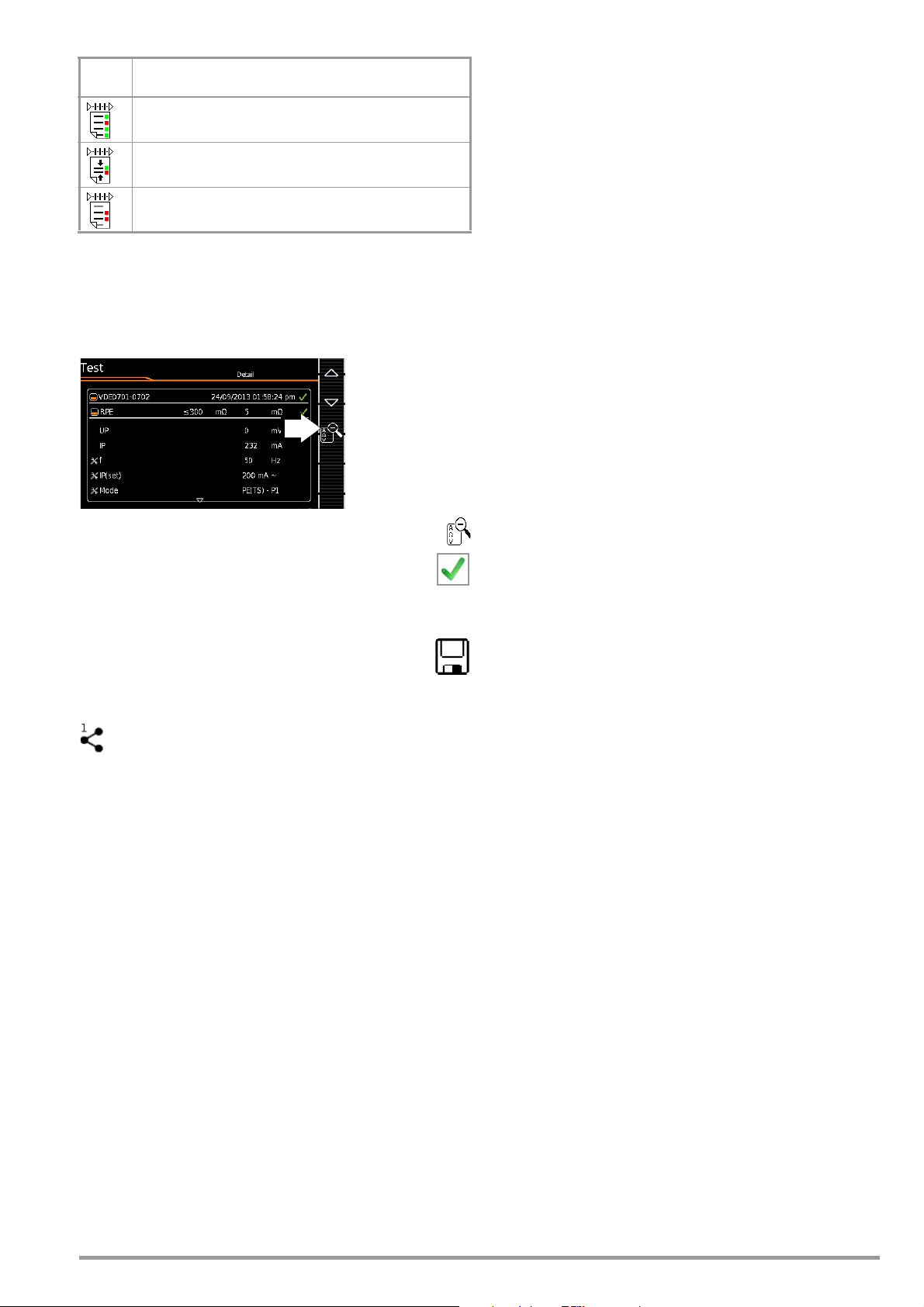
Filter
Meaning of the Selectable Report View
Icon
During report display:
show complete test report
During report display:
show summarized (abridged) test report *
During report display:
show failed test steps only
* Skipped test steps are not shown in the abridged view – only the worst measured
value for each measurement type is shown.
Taking measuring error into consideration depends on the setting
in the setup menu in the SETUP switch position: Setup 1/3 > Auto
Measurements> BMU Considered. > Yes )
Display of Details for Individual Test Steps
➭ The display is returned to the list of test steps by pressing
the magnifying glass key.
➭ The memory screen is displayed again after acknowl-
edging the list.
10.11 Saving Test Results
➭ Save the results of a successful test sequence by
pressing the Save key.
or
Send measurement data to PC (feature KD01, “Z853S –
SECUTEST DB COMFORT”)
via USB or
Bluetooth
e.g. for saving to IZYTRONIQ report generating software
(push-print function) (see IZYTRONIQ online help for descrip-
tion)
Observe notes regarding storage in section 7.
®
(feature M01),
GMC-I Messtechnik GmbH 69
Page 70
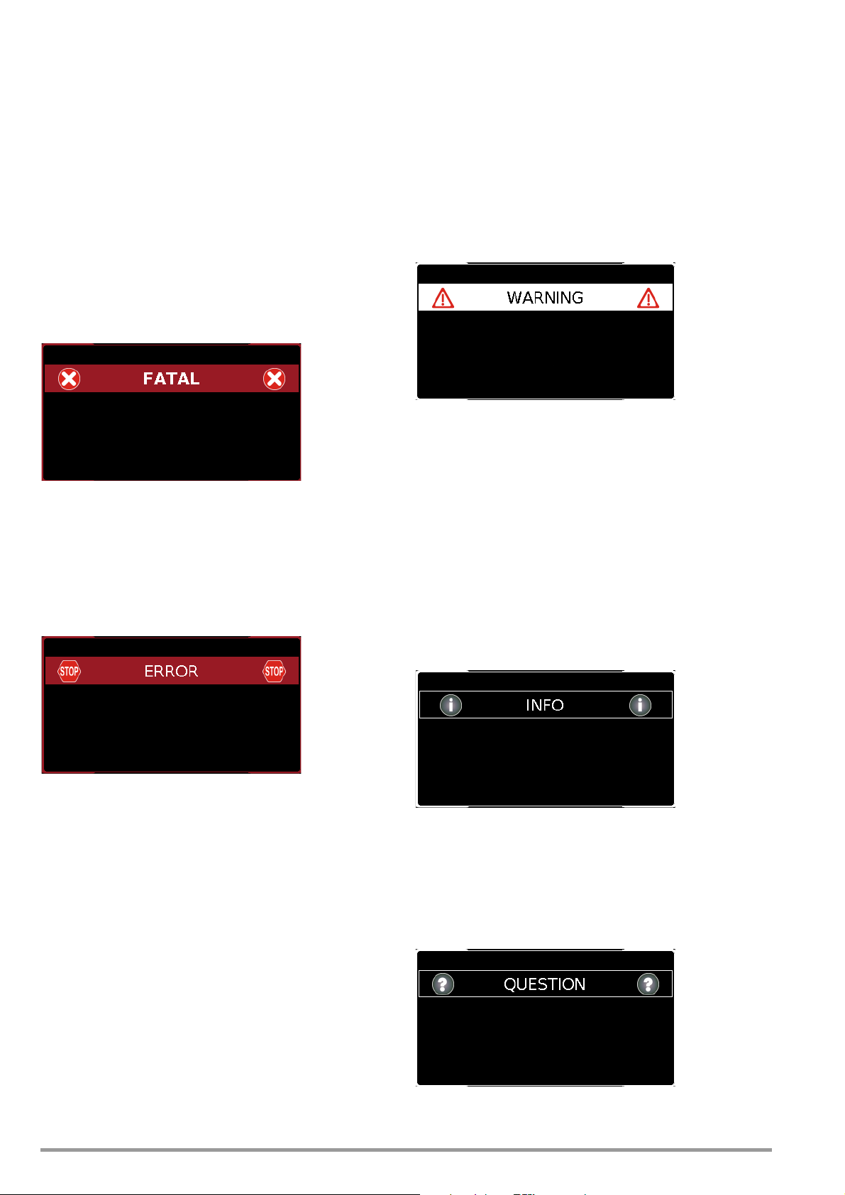
11 Warnings, Error Messages and Notes
Error messages or notes regarding the individual tests or test
sequences are displayed as popups.
Differentiation is made amongst 5 types of messages:
• Fatal error
•Error
• Warning
• Note – INFO
•Question
Fatal error
This message indicates an extraordinary error. Fatal errors have to
be acknowledged or cleared by pressing the OK key, and the
cause of error must be eliminated before the test or the test
sequence can be resumed.
Error
This message indicates, for example, operator errors. These
errors have to be acknowledged or cleared by pressing the OK
key, and the cause of error must be eliminated before the test or
the test sequence can be resumed.
Examples:
• Object cannot be created. General database error!
Warning
Warnings indicate hazards which, if not avoided, may result in
severe injury. Single test: The warning has to be acknowledged or
cleared by pressing the OK key before the test or the test
sequence can be resumed.
Test sequence: The test sequence can be aborted or resumed
without acknowledging.
Examples:
• Caution: Line voltage will be switched to the test socket!
• Caution: Line voltage polarity will be reversed at the test
socket!
Note – INFO
A note is either information regarding the functions executed by
the test instrument or instructions which may have to be acknowledged or skipped by pressing the OK key.
Examples:
•Probe Test
• Set up in a well-insulated fashion?
•On test
• Short-circuit test (L-N)
• Short-circuit test (LN-PE)
• Prompt: Contact with test probe P1 ...
• Prompt: Switch the DUT on/off with its own mains switch ...
• Prompt: Start up / shut down the DUT ...
Question
Questions must be answered by pressing Yes or No before the single test or test sequence is resumed.
Example:
• Device not found!
Create new object/database?
70 GMC-I Messtechnik GmbH
Page 71
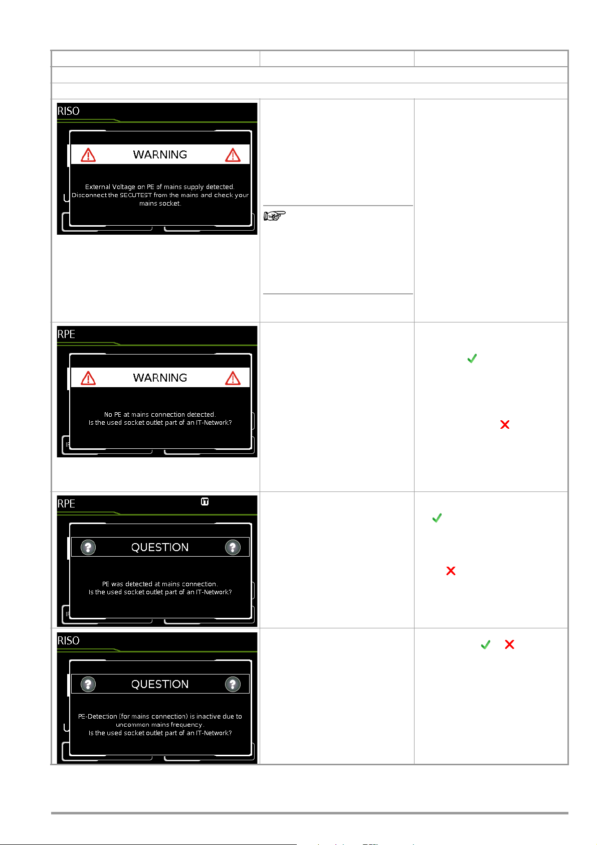
11.1 List of error messages
Note
Error Messages Possible Causes Corrective Measures
Mains Connection Errors
– Protective conductor PE at the
mains outlet at which the SECUTEST is being operated is conducting voltage! This detection function
makes use of the metallized
START/STOP key on the test
instrument. In order for detection to
function correctly, it must be possible to establish reference to earth
potential via the user’s finger.
If the user’s finger is insulated
from the key when it’s
pressed, this error message
may occur although the installation is OK (see “Automatic
Recognition of Mains Connection Errors” onpage 10).
PE connection not detected (at the
outlet at which the test instrument is
being operated):
– If the installation is defective!
– In the case of special types of TT
systems; detection may fail in this
case.
– If the test instrument is being oper-
ated in an IT system
As opposed to the previously used
mains connection, PE was detected
while the IT system option was activated in setup.
➭ Please remove the SECUTEST’s
mains plug from this outlet and arrange to have the outlet/installation inspected by a qualified
electrician without delay. Do not
operate any other devices at this
electrical outlet before this inspection has been completed.
➭ In order to ensure that detection
functions reliably, repeat the interference voltage test and observe
the following tips:
– Unplug all USB devices from the
SECUTEST’s USB ports.
– Remain in contact with a
grounded object while pressing
the START/STOP key
(e.g. a heating pipe).
– Do not contact the START/STOP
key with an object or while wearing
gloves.
➭ If the test instrument is being oper-
ated in an IT system:
Acknowledge the question by
pressing – the IT system option
is activated in this case.
➭ If it’s not an IT system: remove the
mains plug from the outlet and inspect the installation without delay!
➭ If it’s a TT system without neutral
conductor, press ; direct leakage current measurements are
possible.
(Please make absolutely sure that
direct leakage current measurements are possible in your current
mains type!)
➭ Operation in an IT system: Re-
spond to the question by pressing
.
The IT system option remains active as a result.
➭ Operation in a TN or TT system:
Respond to the question by pressing . As a consequence, the IT
system option is deactivated.
Line frequency is less than 48 or
greater than 62 Hz.
GMC-I Messtechnik GmbH 71
➭ PE detection does not work in this
case: select or , depending
on whether or not the utilized system is an IT system.
Page 72
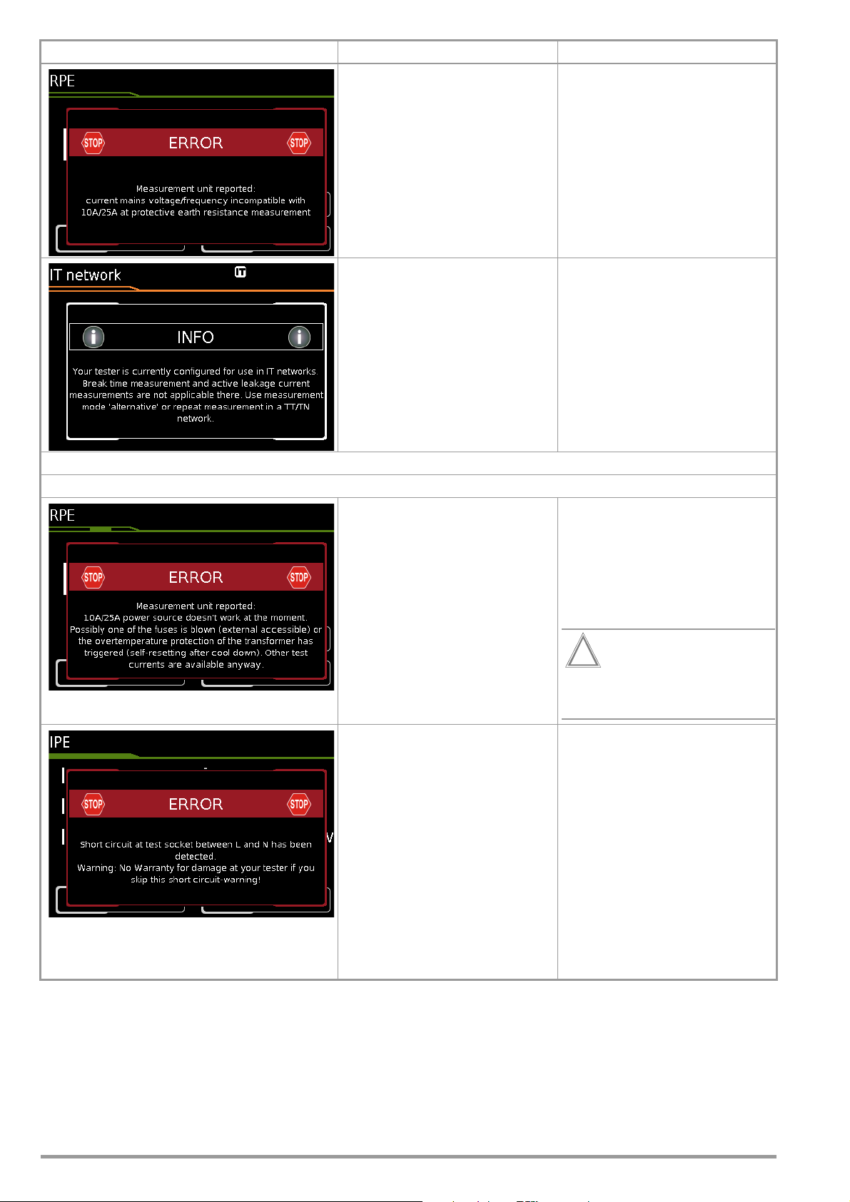
Attention!
!
Error Messages Possible Causes Corrective Measures
– Momentary line voltage at the
SECUTEST test instrument is outside of the range permitted for a
10 A/25 A-R
to 120 V or 220 to 240 V).
measurement (110
PE
➭ The 10 A/25 A-R
is only available when line voltage
is between 220 V and 240 V or
110 V and 120 V at 50 Hz or
60 Hz.
➭ If you’re working with the SECUT-
EST in a system which does not lie
within this voltage range, use one
of the 200 mA test currents in
order to determine protective conductor resistance.
PE
measurement
Connection Error at the Test Socket
– IT system option (see section
4.1.1, “Measurements in IT Systems”) is activated. An attempt has
been made to start an active leakage current measurement or a
measurement with reference to PE
at the mains connection end (or a
test sequence which includes such
measurements).
– Test probe P1 is not connected.
or
– The test instrument’s 10 A/25 A
transformer is overheated.
or
– One of the fuses has blown (fuse
holder in close proximity to the
mains input).
➭ Select measurement type “pas-
sive”.
or
➭ Conduct the desired tests in a TT/
TN system instead of an IT system
and configure the SECUTEST ac-
cordingly.
or
➭ Deactivate leakage current mea-
surements in the sequence param-
eters if possible.
➭
Repeat measurement with probe P1
connected.
➭ Check the fuses and replace if nec-
essary.
➭ Select a different test current (e.g.
200 mA) or wait until the trans-
former has cooled down and then
repeat the measurement.
The 10 A/25 A measurement
is not suitable for continuous
operation!
– A short-circuit has been detected
at the test socket between L and
N.
➭ Determine whether or not the de-
vice under test is defective.
➭
In the case of DUTs which are intended
for operation at an outlet that’s pro-
tected with a 16 A fuse, a short-circuit
may be detected under certain circum-
stances if, for example, they include a
PTC resistor (e.g. large floodlights).
Be sure to use a 3-phase test adapter
in order to test devices of this sort (e.g.
the AT3-IIIE).
➭ You can skip this short-circuit mes-
sage at your own risk and place
the device under test into service.
Any damage resulting from skip-
ping this warning is excluded from
the guarantee!
72 GMC-I Messtechnik GmbH
Page 73
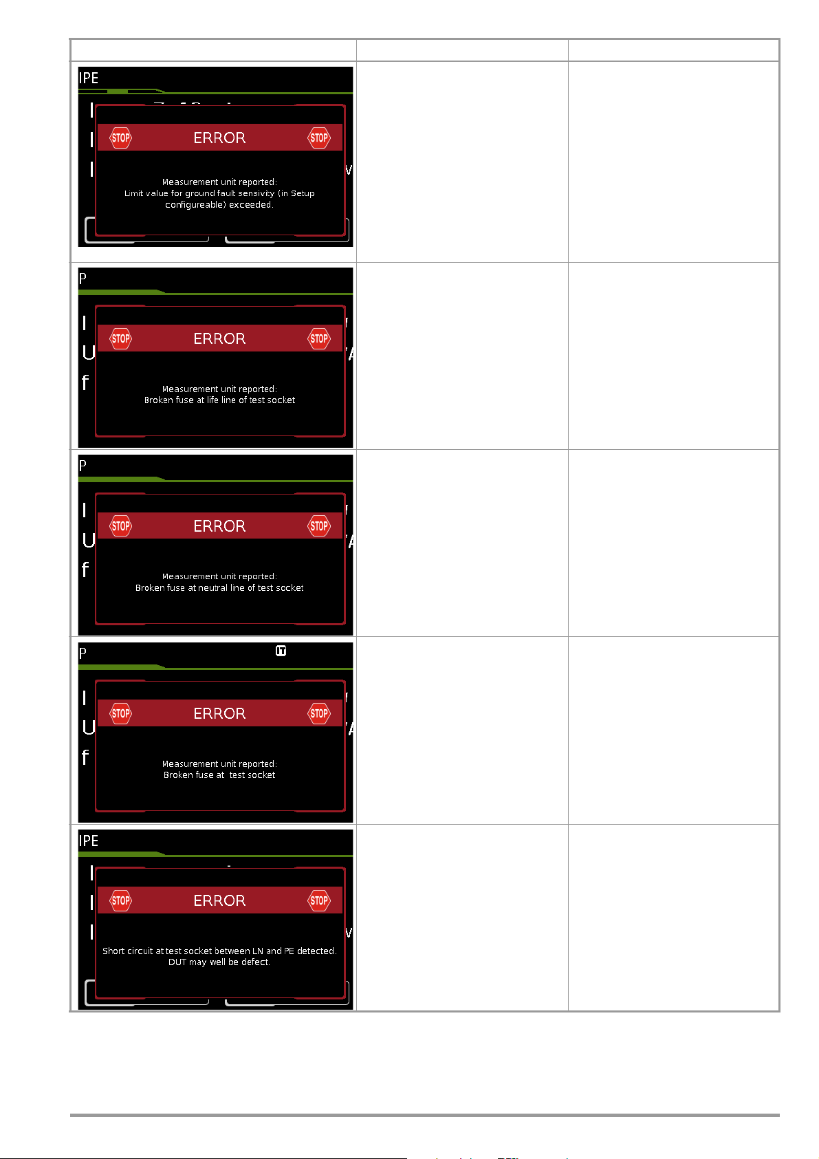
Error Messages Possible Causes Corrective Measures
– A device under test is connected to
the SECUTEST and has been
started up, whose leakage current
(measured by means of the differential current method) exceeds the
limit value specified in setup.
– The fuse for the test socket’s L
conductor has blown
(fuse link 2).
➭ If the device under test normally
generates a leakage current of
greater than 10 mA (e.g. large
heaters), temporarily increase the
“residual current protection” value
selected in setup to 30 mA and try
again.
➭ If values of this magnitude are not
to be expected for the respective
device under test, or if the “residual
current protection” value has already been set to 30 mA in Setup,
there may be a ground fault at the
DUT.
➭ Disconnect the test instrument
from the mains and inspect the
fuses next to the SECUTEST’s
mains connection.
– The fuse for the test socket’s N
conductor has blown
(fuse link 1).
– One of the two fuses for the test
socket has blown
(fuse link 1 or 2).
– A short-circuit has been detected
at the test socket between L/N and
PE.
➭ Disconnect the test instrument
from the mains and inspect the
fuses next to the SECUTEST’s
mains connection.
➭ Disconnect the test instrument
from the mains and inspect the
fuses next to the SECUTEST’s
mains connection.
➭ Determine whether or not the de-
vice under test is defective. Repeat
the visual inspection.
GMC-I Messtechnik GmbH 73
Page 74

Error Messages Possible Causes Corrective Measures
– A short-circuit has been detected
at the test socket between L and
N.
– A short-circuit has been detected
at the test socket between L/N and
PE.
➭ Determine whether or not the de-
vice under test is defective.
➭ In the case of DUTs which are in-
tended for operation at an outlet
that’s protected with a 16 A fuse, a
short-circuit may be detected
under certain circumstances if, for
example, they include a PTC resis-
tor (e.g. large floodlights). Be sure
to use a 3-phase test adapter in
order to test devices of this sort
(e.g. the AT3-IIIE).
➭ You can deactivate this short-cir-
cuit test in the sequence parame-
ters at your own risk.
➭ Determine whether or not the de-
vice under test is defective. Repeat
the visual inspection.
General Application Errors
– The inspector to be deleted is cur-
rently selected and thus cannot be
deleted!
– The 25 A measurements takes too
long.
or
– The 25 A measurement has been
executed too often (without
pauses).
➭ Activate a different inspector before
deleting.
➭ Wait until the test instrument has
cooled down and then restart the
measurement.
74 GMC-I Messtechnik GmbH
Page 75

Error Messages Possible Causes Corrective Measures
Database Processing Error
– One of the fields was filled in with
invalid content while processing an
existing database object.
➭ Please be certain to complete all
mandatory fields (identified in red).
➭ If necessary, check your entries to
the fields for invalid special characters.
– The ID field was not filled in while
creating a new device.
– There’s already an object with the
same ID under the “Customer”
database object.
Error while writing the “.secu” file to the
USB flash drive
There’s not (no longer) enough available memory space on the storage
medium.
– In particular in the case of FAT16
formatted USB flash drives: Too
many files on the USB flash drive
– Power consumption of the utilized
USB flash drive exceeds 500 mA.
– The USB flash drive has been dis-
connected during data import.
– The USB flash drive is defective or
incompatible with the SECUTEST.
➭ Fill in the ID field.
An incorrect barcode has been
selected.
➭ Assign another ID.
Make sure that at least 100 MB is
available on the USB flash drive or
delete any data files which are no longer required.
➭
If the problem persists, save the data
from the USB flash drive on another
storage device and reformat the USB
flash drive (FAT32).
➭ Only use USB flash drives with
power consumption of less than
500 mA in combination with the
SECUTEST.
➭ Make sure that the USB flash drive
is not disconnected or moved until
the entire data export process has
been completed.
➭ If none of these measures results in
improvement, replace the USB
flash drive. A list of tested USB
flash drives is included in section
14.3.
GMC-I Messtechnik GmbH 75
Page 76

Error Messages Possible Causes Corrective Measures
Error while writing the data backup file to
the USB flash drive
There’s not (no longer) enough available memory space on the storage
medium.
– In particular in the case of FAT16
formatted USB flash drives: Too
many files on the USB flash drive
– Power consumption of the utilized
USB flash drive exceeds 500 mA.
– The USB flash drive was discon-
nected during data import.
– The USB flash drive is defective or
incompatible with the SECUTEST.
Moving of an object has failed
Moving a test object would lead to an
ID conflict. The ID already exists for this
customer.
➭ Make sure that a at least 100 MB is
available on the USB flash drive or
delete any data files which are no
longer required.
➭ If the problem persists, save the
data from the USB flash drive on
another storage device and reformat the USB flash drive (FAT32).
➭ Only use USB flash drives with
power consumption of less than
500 mA in combination with the
SECUTEST.
➭ Make sure that the USB flash drive
is not disconnected or moved until
the entire data backup process has
been completed.
➭ If none of these measures results in
improvement, replace the USB
flash drive. A list of tested USB
flash drives is included in section
14.3.
➭ Delete the object with duplicate ID.
➭ Select another customer as a relo-
cation target.
Errors during Operation with Barcode Scanner or RFID Scanner
– The scanned barcode is too long.
– While writing an RFID tag an
attempt was made to write an ID to
the tag with vowel mutations such
as ä, ü or ö, or with special charac-
ters.
➭ Change vowel mutations such as ä
to ae.
➭ Avoid the use of special characters
in the ID.
76 GMC-I Messtechnik GmbH
Page 77

Error Messages Possible Causes Corrective Measures
Printer Connection Error
– The printer is not connected.
– An incompatible printer has been
connected.
➭ Connect the printer to the USB
port before pressing the PRINT key.
➭ Make sure that the utilized printer is
listed in section 14.1, “List of Suitable Printers with USB Port”.
– No recording chart in the thermal
printer.
– The printer is defective.
– The device ID to be printed as a
barcode contains an inadmissible
character, for example vowel mutation or special character, or it fails
to conform to the conventions
which apply to the selected barcode encryption type (e.g. EAN 13:
only numeric characters, overall
length 13 characters, last character
as check digit only).
– A 3.5 or 6 mm tape cartridge has
been inserted into the printer
– these tape sizes are inappropriate for 2D code printing.
➭ Insert a new recording chart.
➭ Select other barcode encryption
(SETUP => Printer => Z721E =>
Printer Settings => Encryption
➭ Change vowel mutations such as ä
to ae.
➭ Avoid the use of special characters
in the ID.
➭ Adjust the ID to the specified
length for the selected type of barcode encryption.
➭ Insert cartridges with a tape width
of 9 mm (or preferably 12 mm or
more) and repeat printing.
or
➭ Change to CODE128, CODE39 or
EAN13 in SETUP.
– A 9 mm tape cartridge has been
inserted into the printer – this tape
size is inappropriate for QR code
label printing.
GMC-I Messtechnik GmbH 77
➭ Insert a cartridge with a tape width
of 12 mm and repeat printing.
or
➭ Change to another output format in
SETUP (MicroQR code, DataMa-
trix, Aztec, Code128, Code39 or
EAN13).
Page 78

Error Messages Possible Causes Corrective Measures
– Too many data in the ID to be
printed as a Micro QR code.
– The ID is too long to be printed as
a Micro QR code.
➭ Shorten the ID or change to an-
other output format in SETUP (QR
Code, DataMatrix, Aztec,
Code128, Code39, EAN13).
78 GMC-I Messtechnik GmbH
Page 79

11.2 List of Possible DUT Connections Depending on Measurement Type
Measurement Type Suitable for DUT Connection via
RPE
PE(TS) - P1 passive Test socket, EL1 test socket, VL2E, AT3-IIIE, AT3-IIS, AT3-
IIS32, AT16DI/AT32DI
PE(TS) - P1 active Test socket (for PRCDs)
PE(mains) - P1 Permanent connection
PE(mains) - P1 clamp Permanent connection
P1 - P2 Permanent connection
RINS
LN(TS) - PE(TS) Test socket, EL1, VL2E, AT3-IIIE, AT3-IIS, AT3-IIS32, AT16DI/
AT32DI, CEE adapter
LN(TS) - P1 Test socket, VL2E, AT3-IIIE, AT3-IIS, AT3-IIS32, AT16DI/AT32DI
P1 - P2 No connection (PC3)
PE(mains) - P1 Permanent connection
PE(TS) - P1 Test socket
LN(TS) - P1//PE(TS) Test socket, VL2E, AT3-IIIE, AT3-IIS, AT3-IIS32, AT16DI/AT32DI
IPE
Direct Test socket, AT16DI/AT32DI (direct or diff.)
Differential Test socket
Alternative Test socket, VL2E, AT3-IIIE, AT3-IIS, AT3-IIS32, AT16DI/AT32DI
AT3 adapter AT3-IIIE, AT3-IIS, AT3-IIS32
Clamp Permanent connection
IT
Direct Test socket, AT3-IIIE, AT3-IIS, AT3-IIS32, AT16DI/AT32DI
Differential Test socket
Alternative (P1) Test socket, AT3-IIIE, AT3-IIS, AT3-IIS32, AT16DI/AT32DI, VL2E
Permanent connection Permanent connection
Alternative (P1–P2) No connection (PC3)
IE
Direct Test socket, AT16DI/AT32DI (only diff. is sensible)
Differential Test socket
Alternative Test socket, AT16DI/AT32DI
AT3 adapter AT3-IIIE, AT3-IIS, AT3-IIS32
Clamp Permanent connection
IA
Direct (P1) Test socket
Alternative (P1) Test socket
Perm. con. (P1) Permanent connection
IP
Direct (P1) Test socket
Perm. con. (P1) Permanent connection
U probe
PE - P1 Permanent connection
PE - P1 (with mains) Test socket
U meas.
V - COM Permanent connection
V - COM (with mains) Test socket
tA
mains to test socket Test socket
P
Function test Test socket, AT3-IIIE, AT3-IIS, AT3-IIS32, AT16DI/AT32DI, CEE
adapter
EL1
EL1 adapter EL1 and test socket
AT3-IIIE adapter AT3-IIIE
VL2E adapter VL2E
Temperature
V-COM PT100(0) Permanent connection
Current (via clamp)
V-COM Permanent connection
V-COM (with mains) Test socket
Measurement Type Suitable for DUT Connection via
PRCD time to trip
— Test socket
GMC-I Messtechnik GmbH 79
Page 80
12 Characteristic Values
Func-
tion
t
A
PRCD
I
Leaka
ge
Tem p
Tests, 62638 (DIN VDE 0701-0702) / IEC 62353 (VDE 0751)
Function test at the test socket
Voltage measurement
Measured
Quantity
Protective conduc-
tor resistance
R
PE
Insulation resis-
tance
RINs
Leakage current
Alternative
Measurement
IPE, IT, IE, IA
Leakage current
Direct measure-
ment
IPE, IT, IE, IA, IP
Leakage current
Differential cur-
rent measure-
ment
IPE, IT, IE
Line voltage
10
U
L–N
Load current I
Active power P
Apparent power S
Powe r factor PF
with sinusoidal
waveform: cosϕ
Line frequency f
Time to Trip
Probe voltage
(probe P1 to PE)
, and
Measuring voltage
(V–COM
sockets
, and
Leakage current
via AT3-IIIE
adapter Z745S
Temperature
with Pt100 sensor
Temperature
with Pt1000 sensor
Display Range/
Nominal Range of
Use
1 … 999 mΩ 1mΩ
1.00 ... 9.99 Ω 10 mΩ
10.0 … 27.0 Ω
10 … 999 kΩ 1kΩ
1.00 … 9.99 MΩ 10 kΩ
9
10.0 … 99.9 MΩ 100 kΩ
100 … 300 MΩ 1MΩ
0 ... 99 μA1μA
100 ... 999 μA1μA
2
1.00 ... 9.99 mA 10 μA
10.0 ... 30.0 mA 100 μA
Ip only: 0.0 ...
99.9 μA
3
4
0 ... 99 μA1μA
100 ... 999 μA1μA
1.00 ... 9.99 mA 10 μA
10.0 ... 30.0 mA 100 μA
0 ... 99 μA1μA
100 ... 999 μA1μA
1.00 ... 9.99 mA 10 μA
10.0 ... 30.0 mA 100 μA
100.0 … 240.0 V~ 0.1V— — ———— —±(2% rdg.+2 d)
0 … 16.00 A
L
0 … 3700 W 1 W — — — — — — —
0 … 4000 VA 1 VA Calculated value, U
0.00 … 1.00 0.01 Calculated value, P / S, display > 10 W ±(10% rdg.+5 d) 264 V
0 ... 420.0 Hz 0.1 Hz — — — — — — —
0.1 ... 999 ms 0.1 ms — — 30 mA — — —
0.0 ... 99.9 V
100 ... 264 V
0.0 ... 99.9 V
6
)
100 ... 300 V
0.00 ... 0.99 mA
1.0 ... 9.9 mA
6, 8
10 ... 20 mA
– 200.0 ...
+850.0 °C
– 150.0 ...
+850.0 °C
Nominal
Reso-
Voltage
lution
100 m
Ω
50 … 500
VDC
100 nA
10mA— — ———— —±(2% rdg.+2 d)
RMS
100 mV
1 V
0.01 mA
0.1 mA
1mA
0.1 °C— <20V– 1.1mA— — — ±(2% rdg.+1 °C) 10 V
OpenCircuit
Voltage
U
N
< 24 V
—
AC or DC
1.0 • U
1.5 • U
—
250 V~
– 20/+10%
————
— — ————
————
— — ———— —
Nomi-
Short-
nal
Circuit
Current
I
I
N
>
200 mA
AC / DC
> 10 A AC
—
>
35 A AC
11
>1mA <2mA — —
—<1.5mA
U
50 ...
Current
0
…
N
N
Internal
K
5
> 150 k
Refer-
Resis-
±10 Ω
ence
Resis-
tance
tance
R
I
R
REF
——
1kΩ
Ω
±10 Ω
1kΩ
1kΩ
• I
L–N
V
3 MΩ
——
1 MΩ
Measuring
Uncertainty
±(15% rdg.+ 10 d)
>10d
> 10.0 Ω :
±(10% rdg.+ 10 d)
±(5% rdg.+ 4 d)
>10d
≥ 20 MΩ :
±(10% rdg.+ 8 d)
±
(5% rdg.+ 4 d) > 10 d
> 15 mA:
±(10% rdg.+ 8 d)
±(5% rdg.+ 4 d)
> 10 d
±(5% rdg.+ 4 d)
> 10 d
±
5 ms — 264 V
Intrinsic
Uncertainty
±
(10% rdg.+ 10 d)
>10d
±
(2.5 % rdg.+2 d)
> 10 d
≥ 20 MΩ :
±
(5% rdg.+4 d)
±
(2% rdg.+2 d) > 10 d
> 15 mA:
±
(5% rdg.+ 4 d)
±
(2.5 % rdg.+2 d)
> 10 d
±
(2.5 % rdg.+2 d)
>10d
±
(5 % rdg.+10 d)
>20d
±
(5 % rdg.+10 d)
>20d
±
(2% rdg.+2 d)
±
(2% rdg.+2 d)
±
(2 % rdg.+2 d)
> 45 Hz ... 65 Hz
±
(2 % rdg.+5 d)
> 65 Hz ... 10 kHz
±
(5 % rdg.+5 d)
> 10 kHz ... 20 kHz
±(2 % rdg.+2 d)
>10d
without adapter
Overload
Capacity
Value Time
264 V
250 mA
Continu-
16 A AC
5
>
42 A AC
264 V
264 V
264 V
264 V
264 V
264 V
264 V
264 V
264 V
300 V
and
253 V
15 s
11
Continu-
Continu-
Continu-
Continu-
Continu-
Continu-
16 A
Continu-
20 A 10 min.
Continu-
Continu-
Continu-
Continu-
Continu-
,
Continu-
Continu-
ous
ous
ous
ous
ous
ous
ous
ous
ous
ous
ous
ous
ous
ous
ous
80 GMC-I Messtechnik GmbH
Page 81
Func-
tion
Measured
Quantity
Current via
Display Range/
Nominal Range of
Use
1 ... 99 mA
current clamp
6, 7
)
0.1 ... 0.99 A
1.0 ... 9.9 A
10 ... 300 A
0.1 ... 9.9 mA
sensor
[1 mV : 1 mA]
(V–COM
sockets
Current via
6, 7
)
10 ... 99 mA
0.10 ... 0.99 A
1.0 ... 30.0 A
0.01 ... 0.99 mA
I
Clamp
current clamp
sensor
[10mV : 1mA]
(V–COM
sockets
Current via
6, 7
1.0 ... 9.9 mA
)
0.10 ... 3.00 A
10 ... 99 mA
1 ... 99 μA
current clamp
sensor
[100 mV : 1 mA]
(V–COM
sockets
Current via
6, 7
)
0.10 ... 0.99 mA
1.0 ... 9.9 mA
10 ... 300 mA
current clamp
sensor
[1000 mV : 1 mA]
(V–COM
sockets
2
Known as equivalent leakage current or equivalent patient leakage current from
previous standards
3
Protective conductor current, touch current, device leakage current, patient leakage current
4
Protective conductor current, touch current, device leakage current
5
Only with feature G01, e.g. SECUTEST BASE10/SECUTEST PRO and SECULIFE ST BASE
6
Only with feature I01, e.g. SECUTEST PRO and SECULIFE ST BASE
7
Measurement types IPE_clamp and IG_clamp
8
Measurement type IPE_AT3 adapter and IG_AT3 adapter
9
The upper range limit depends on the selected test voltage.
10
Voltage at the test socket may be lower than measured line voltage due to components which limit inrush current.
11
Only with feature G02, e.g. SECULIFE ST BASE25
Resolution
1mA
(1 mV)
0.01 A
(10 mV)
0.1 A
(100 mV)
1A
(1 V)
0.1 mA
(1 mV)
1mA
(10 mV)
0.01 A
(100 mV)
0.1 A
(1 V)
0.01 mA
(1 mV)
0.1 mA
(10 mV)
1mA
(100 mV)
0.01 A
(1 V)
1μA
(1 mV)
0.01 mA
(10 mV)
0.1 mA
(100 mV)
1mA
(1 V)
Nominal
Voltage
Open-
Circuit
Voltage
U
N
— — ———— —
— — ———— —
— — ———— —
— — ———— —
Nomi-
nal
Current
U
0
Key: rdg. = reading (measured value), d = digit(s)
Testing Times, Automated Sequence
Testing times (“measurement duration” parameter) can be set separately
for each rotary switch position during configuration of the sequence
parameters. Testing times are neither tested nor calibrated.
Emergency Shutdown During Leakage Current Measurement
As of 10 mA of differential current (can also be set to 30 mA),
automatic shutdown ensues within 500 ms. This shutdown does
not take place during leakage current measurement with clamp
meter or adapter.
Resis-
tance
R
I
Refer-
ence
Resis-
tance
R
REF
Measuring
Uncertainty
Intrinsic
Uncertainty
±(2 % rdg.+2 d)
20 Hz ... 20 kHz
without clamp
Short-
Internal
Circuit
Current
I
I
N
K
Influencing Quantities and Influence Error
Influencing Quantity /
Sphere of Influence
Change of position E1 —
Change to test equipment supply
voltage
Temperature fluctuation
°C2.5
0 ... 40
Amount of current at DUT E4 2.5
Low frequency magnetic fields E5 2.5
DUT impedance E6 2.5
Capacitance during insulation measurement
Waveform of measured current
49 … 51 Hz
45 … 100 Hz 1 (for touch current)
Designation
per
IEC 61557-16
E2 2.5
E3
E7 2.5
E8
Influence Error
± … % rdg.
Specified influence error valid
starting with temperature changes
as of 10 K:
2 with capacitive load
(for equivalent leakage current)
2.5 for all other measuring ranges
>10d
Overload
Capacity
Value Time
Continu-
253 V
ous
GMC-I Messtechnik GmbH 81
Page 82

Reference Ranges
Line voltage 230 V AC ± 0.2%
Line frequency 50 Hz ± 2Hz
Waveform
Sine (deviation between effective and rectified value < 0.5%)
Ambient
Tem pe ra tu re + 2 3 °C ±2K
Relative humidity 40 … 60%
Load resistance Linear
Nominal Ranges of Use
Nominal line voltage 100 V … 240 V AC
Nominal line frequency
50 Hz ... 400 Hz
Waveform
of the line voltage Sinusoidal
Tem pe ra tu re 0 °C … +40°C
Ambient Conditions
Storage temperature – 20 °C … +60°C
Relative humidity max. 75%, no condensation allowed
Elevation max. 2000 m
Place of use
Indoors, except within specified ambient
conditions
In order to avoid deviation due to excessive temperature fluctua-
tion, e.g. after transport in low outdoor temperatures and subsequent operation in a warm indoor environment, it’s advisable to
wait until the test instrument has acclimatized before starting any
measurements.
If the test instrument is colder than the ambient air, condensation
may occur at high humidity, i.e. condensate may accumulate on
components. This could result in the occurrence of parasitic
capacitances and resistances which, in turn, affect the measuring
circuit and measuring accuracy.
Power Supply
Supply network TN, TT or IT
Line voltage 100 V … 240 V AC
Line frequency 50 Hz ... 400 Hz
Power consumption 200 mA DUT: Approx. 32 VA
10 A DUT: Approx. 105 VA
25 A DUT: Approx. 280 VA
mains to test socket
(e.g. during function test)
Continuous max. 3600 VA, power is con-
ducted through the instrument only,
switching capacity ≤ 16 A, ohmic load, the
AT3-IIS32 (Z745X) adapter (for example)
can be used for current > 16 A AC
Electrical Safety
Protection category I per IEC 61010-1/DIN EN 61 010-1/
VDE 0411-1
Nominal voltage 230 V
Test voltage 2.3 kV AC 50 Hz or 3.3 kV DC
(mains circuit / test socket to mains PE ter-
minal, USB, finger contact,
probe(s) test socket)
Measuring category 250 V CAT II
Pollution degree 2
Safety shutdown
At DUT differential current of > 10 mA,
shutdown time: < 500 ms,
can also be set to > 30 mA
with following probe current during:
–
Leakage current measurement:
> 10 mA~/< 500 ms
– Protective conductor resistance
measurement:
>250mA~/<1ms
in case of continuous current I > 16.5 A
Fuse links Mains fuses: 2 ea. FF 500V/16A
Special fuse: M 250V/250mA
Feature G01: Additional
10 A RPE test current:1 ea. FF 500V/16A
Electromagnetic Compatibility
Product standard DIN EN 61326-1:2013
DIN EN 61326 -2-2: 2013
Interference
emission
EN 55011 B
IEC 61000-3-2 B
IEC 61000-3-3 B
Interference
immunity
EN 61000-4-2 Contact/atmos. – 4 kV/8 kV B
EN 61000-4-3 10 V/m (80 MHz ... 1 GHz) A
EN 61000-4-4 Mains connection – 2 kV B
EN 61000-4-5 Mains connection – 1 kV (LN), 2 kV (LPE) B
EN 61000-4-6 Mains connection – 3 V A
EN 61000-4-8 30 A/m A
EN 61000-4-11 0%: 1 period B
Test Value * Evaluation Criterion
0%: 250/300 periods C
40%: 10/12 periods C
70%: 25/30 periods C
Class
USB data port
Type USB slave for PC connection
Type 2 e a. US B maste r,
for data entry devices * with HID boot
inter
face,
for USB flash drive for data backup,
for USB flash drive for saving
reports as HTML files
for printers *
* See section 14 for compatible devices
As of firmware 1.6.0: In the remote operating mode, the test instru-
ment can be controlled via the USB slave data interface. Pertinent
interface commands are available upon request.
Bluetooth data interface
®
2.1 + EDR
(SECUTEST PRO BT (comfort) or feature M01 only)
Mechanical Design
Display 4.3" multi-display (9.7 x 5.5 cm),
backlit,
480 x 272 pixels
at 24-bit color depth (true color)
Dimensions W x H x D: 295 x 145 x 150 mm
Height with handle: 170 mm
Weight SECUTEST BASE(10)/PRO: approx. 2.5 kg
SECULIFE ST BASE25: approx. 4.0 kg
Protection Housing: IP 40,
Test socket: IP 20 per DIN VDE 0470, part
1/EN 60529
Table Excerpt Regarding Significance of IP
Codes
IP XY
nd
(1
Protection Against Foreign
digit X)
2 ≥ 12.5 mm ∅ 0 Not protected
4 ≥ 1.0 mm ∅ 0 Not protected
Object Ingress
SECULIFE ST BASE(25)
IP XY
(2nd digit Y)
Protection Against Water
Ingress
:
Housing with antimicrobial properties per JIS
standard Z 2801:2000
82 GMC-I Messtechnik GmbH
Page 83
13 Maintenance
Attention!
!
Note
Attention!
!
Attention!
!
13.1 Housing Maintenance
No special maintenance is required for the housing. Keep outside
surfaces clean. Use a slightly dampened cloth for cleaning. Avoid
the use of cleansers, abrasives and solvents.
13.2 Testing the Color Display and the Buzzer (self-test parameter)
The color display can be tested for failure of individual segments
and loss of color components on page 3/3 of the setup menu in
the SETUP switch position under the self-test parameter.
Beyond this, the buzzer can be tested for 3 different frequencies.
13.3 Software Update (system info parameter)
The current firmware or software version can be queried via the
system info parameter (Setup 3/3).
The test instrument’s firmware can be updated via the USB port
with the help of a PC. Updating is only possible via the proprietary
Firmware Update Tool application.
➭ Before updating your test instrument’s firmware, make sure
that your PC software is compatible with the current firmware
version (see table below).
Te st
Instrument
Firmware
Version
1.8.1 ETC .etc ✔✔
1.8.2 ETC .etc ✔ 1.5
1.8.3 ETC .etc ✔ 1.5
2.0.0 IZYTRONIQ .etc ✔ IZYTRONIQ
2.1.1 IZYTRONIQ .secu
As a registered user (if you’ve registered your test instrument),
you’re entitled to download the Firmware Update Tool and the cur-
rent firmware version free of charge from the myGMC page at
www.gossenmetrawatt.com.
You’ll also find operating instructions for the firmware update tool
here.
PC Report
Generating
Software
Before updating the firmware, be sure to save the structures you have created and your measuring data, because they might be deleted during the update process
(see section 5.2.3, “Backing Up and Restoring Test
Structures and Measurement Data”).
Adjustment data are not overwritten during updating, and
thus recalibration is unnecessary.
The interface cable may not be disconnected while updating the firmware via the USB port.
Data Export/
Import File
Formants
Report
Designer
(see Section
3.5.3)
Sequence
Designer
IZYTRONIQ
If backup battery voltage is too low, the date and time assigned to
the test data no longer correspond to the actual time of recording.
This may also influence sorting in the report generating software.
The instrument’s database itself is not affected by a depleted
backup battery.
13.5 Fuse Replacement
The fuses may only be replaced when the instrument is voltagefree, i.e. the instrument must be disconnected from mains supply
power and may not be connected to a measuring circuit.
The fuse type must comply with the specifications in the technical
data or the labeling on the instrument.
13.6 Recalibration
The measuring tasks performed with your instrument, and the
stressing it’s subjected to, influence aging of its components and
may result in deviation from the specified levels of accuracy.
In the case of strict measuring accuracy requirements, as well as
in the event of use at construction sites with frequent stress due
to transport and considerable temperature fluctuation, we recommend a relatively short calibration interval of once per year. If your
instrument is used primarily in the laboratory and indoors without
considerable climatic or mechanical stressing, a calibration interval of once every 2 to 3 years is sufficient as a rule.
During recalibration * at an accredited calibration laboratory
(DIN EN ISO/IEC 17025), deviations from traceable standards
demonstrated by your measuring instrument are documented.
Ascertained deviations are used to correct display values during
later use of the instrument.
We would be happy to perform DAkkS or factory calibration for
you at our calibration laboratory. Further information is available
on our website:
www.gossenmetrawatt.com
(
→
COMPANY → Quality and Certificates → DAkkS-calibration center).
According to DIN VDE 0701-0702, only test instruments which
are tested and calibrated at regular intervals may be used for testing.
Recalibration of your instrument at regular intervals is essential for
the fulfillment of requirements according to quality management
systems per DIN EN ISO 9001.
* Examination of the specification, as well as adjustment, are not included in calibra-
tion. However, in the case of our own products, any required adjustment is performed and adherence to the specification is confirmed.
13.7 Technical Safety Inspections
Subject your test instrument to technical safety inspections at
regular intervals. We recommend the same interval for inspections
as is also used for recalibration.
The SECUTEST... is designed as a totally insulated device in
accordance with IEC 61010 and IEC 61557-16/VDE 0413-16.
The protective conductor is used for measuring purposes only,
and is thus not always accessible. The protective conductor at
the test socket can be tested as follows:
➭
Connect the SECUTEST... to a multiple distributor.
➭ Conduct a touch current measurement for permanently con-
nected DUTs (nothing may be connected to the test socket).
➭
Measure protective conductor resistance between the neighboring socket at the multiple distributor and the test socket.
➭ The measured value may not exceed 0.3 Ω.
For technical reasons, insulation resistance between LN and PE
The test instrument may not be disconnected from supply power while updating the firmware via the USB port.
13.4 Backup Battery for Real-Time Clock
The backup battery (lithium cell) should be replaced no later than
after 8 years. Replacement can only be executed by the service
department.
GMC-I Messtechnik GmbH 83
inside the SECUTEST... is roughly 3 MΩ.
This must be taken into consideration during technical safety
inspections or, instead of the insulation resistance measurement,
the protective conductor current measurement must result in a
value of less than 3.5 mA (or less than 7 mA if the equivalent leakage current method is used).
Page 84
There are also 4 accessible conductive parts on the SECUT-
Note
Note
Note
Note
EST..., at which the touch current measurement must result in a
value of less than 0.5 mA:
• Connector for service plug (jack socket)
•USB ports
• Metallized start key
• Protective conductor bar in the test socket
In order to prevent damage to the SECUTEST... test
instrument, we recommend avoiding the performance of
measurements at the USB ports.
13.8 Returns and Environmentally Sound Disposal
The instrument is a category 9 product (monitoring and control
instrument) in accordance with ElektroG (German electrical and
electronic device law). This device is subject to the RoHS directive. We also make reference to the fact that in this regard, the
current status can be accessed on the Internet at www.gossenmetrawatt.com by entering the search term WEEE.
We identify our electrical and electronic devices in
accordance with WEEE 2012/19/EU and ElektroG
using the symbol shown at the right per DIN EN 50419.
These devices may not be disposed of with the trash.
Please contact our service department regarding the return of old
devices (see address in Section 15).
Text Encryption
Read-out to the CP1252 character set is limited in the
“Text” print-out mode – characters which cannot be displayed are replaced by an underline (_).
14 Appendix
14.1 List of Suitable Printers with USB Port
The following devices have been tested for use with the test
instrument. We are unable to offer any guarantees regarding use
with other devices.
• Z721S thermal printer
• Z721D barcode printer
(as of firmware V1.3.0, to be replaced by Z721E as of 2018)
Setup options in the SETUP switch position
(Setup (2/3) > Printer > Z721D > Printer settings):
Encryption: Code39, Code128, EAN13, Text, QR Code, Micro
QR Code, DataMatrix
The respective paper size is selected automatically as of FW
2.0 (6, 9, 12, 18, 24 or 36 mm).
• Z721E barcode printer (as of firmware V1.8.3)
Setup options in the SETUP switch position
(Setup (2/3) > Printer > Z721E > Printer settings)
Encryption: Code39, Code128, EAN13, Text, QR Code, Micro
QR Code, DataMatrix, Aztec
The respective paper size is selected automatically
(6, 9, 12, 18, 24 or 36 mm).
Label Tapes
When using the label printer together with the SECUTEST..., only TZ(e) tapes are supported with widths of 6, 9,
12, 18, 24 and 36 mm.
2D Code Labels
When printing 2D code labels
(QR Code, MicroQR Code, DataMatrix, Aztec),
we recommend label cartridges with tape widths of
12 mm or more, and in any case at least 9 mm.
84 GMC-I Messtechnik GmbH
Page 85

14.2 List of Suitable Barcode Scanners and RFID Scanners with USB Port
The following devices have been tested for use with the test
instrument. We are unable to offer any guarantees regarding use
with other devices.
• Z751A barcode scanner
• Z751E RFID scanner (programmer)
14.3 Use of USB Storage Devices
USB flash drives must be directly connected to the test instrument for various device functions (see sections 3.8 and 5.2).
The connected USB storage medium must fulfill at least the following requirements in order to be used with your test instrument:
• The file system on the USB flash drive must be FAT formatted
(FAT32). NTFS and exFAT file systems, for example, are not
compatible.
• Maximum current consumption of the USB storage medium
via the USB port may not exceed 500 mA.
• Do not use USB storage devices with encrypting functions.
Furthermore, make sure that the USB drive includes an LED display which indicates whether or not write operations have been
completed.
List of tested and approved USB flash drives:
• Philips USB flash drive Snow Edition USB 3.0
(tested size: 64 GB)
• Toshiba TransMemory-MX U361 USB 3.0
(tested size: 64 GB)
• Corsair Flash Voyager Vega USB 3.0
(tested size: 16 GB)
• SanDisk Cruzer Glide USB 2.0/3.0
(tested size: 64 GB)
GMC-I Messtechnik GmbH 85
Page 86
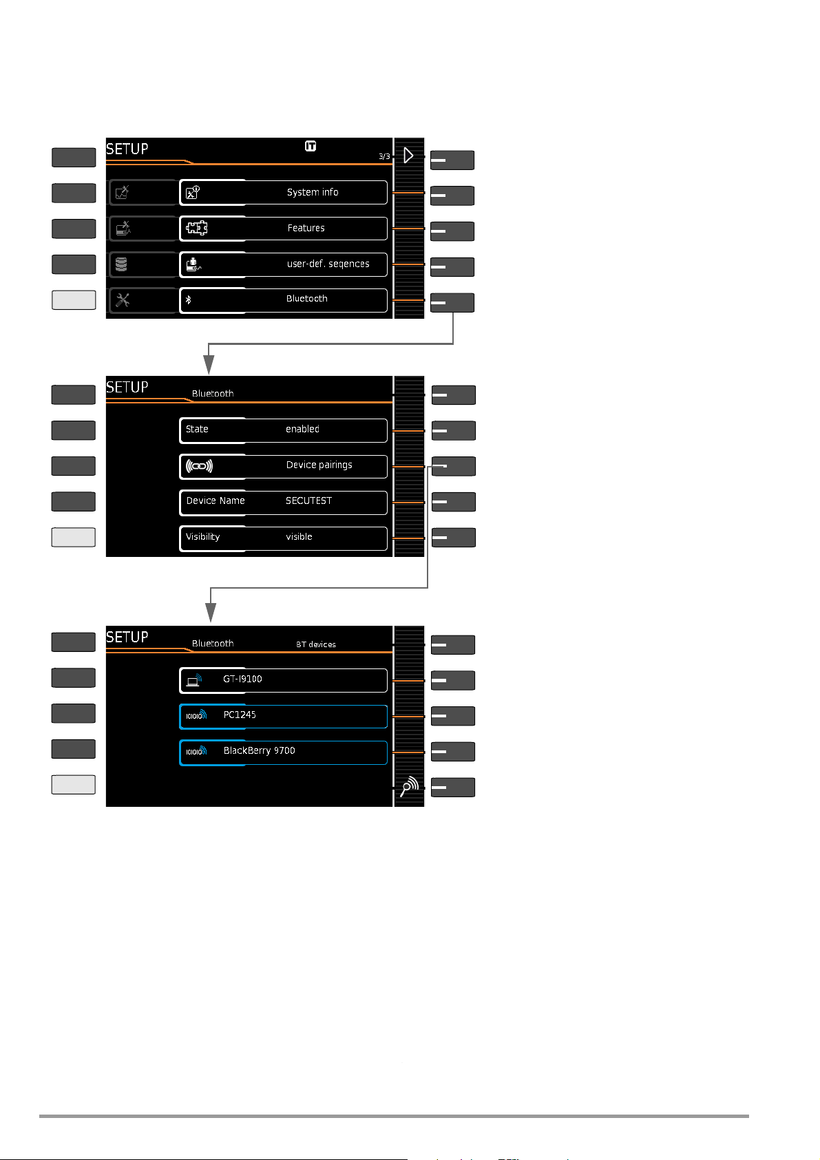
14.4 Bluetooth Interface (SECUTEST PRO BT (comfort) or feature M01)
Menu selection for operating parameters, page 3 of 3
Setup 3/3
Bluetooth: menus for using the Bluetooth
®
interface
Menu selection for Bluetooth operating parameters
Status: Switch Bluetooth interface on/off
Visibility *: Specifies whether the test instrument
can be found by other Bluetooth devices.
Device name *: The name of the test instrument displayed above the interface can be changed.
Device pairings *: Search/pair BT devices, view/
edit existing pairings
* These submenus only appear if status is set to on.
Search for
Bluetooth
®
devices in close proximity
Paired device found
(white frame) > rename or delete
Not yet paired device found
(blue frame) > entry of pairing PIN
Paired device found
(blue frame) > rename or delete
List of already paired devices
PRINT
ESC
HELP
MEM
PRINT
ESC
HELP
MEM
PRINT
ESC
HELP
MEM
The
Bluetooth
(see section 10.10).
®
interface permits use of the push-print function
Important Notes
• Status/visibility: For reasons of safety, we recommend deactivating the Bluetooth
ble” setting cannot be used as a substitute for shutting down
the Bluetooth® interface, because invisible Bluetooth devices
can also be found using the appropriate means.
• Device pairings which will no longer be required for a lengthy
period of time should be deleted.
®
interface if it’s not needed. The “not visi-
•The DUT’s device name is set to SECUTEST as a standard feature. If you access one PC with several test instruments, the
name should be at least supplemented, for example SECUTEST1, SECUTEST2 etc.
14.5 Remote Control Interface
(Feature KB01 or enabling of the “database extension”, “Z853R –
SECUTEST DB+” – available for a fee – is required as of firmware
version 1.6.0.)
The test instrument’s measuring functions can be remote controlled via the USB interface with the help of IZYTRONIQ. In this
case, measured values do not appear at the test instrument’s display and are instead transmitted via the respective data interface.
86 GMC-I Messtechnik GmbH
Page 87

14.6 Entry Via an External USB Keyboard
Instead of using the touchscreen keyboard, characters can be
entered directly with a USB keyboard which is connected to the
test instrument. The touchscreen keyboard which appears at the
display
must be exited to this end.
Switching from On-screen to USB Keyboard Entry
➭ Press the Return key or the ✔ softkey within a popup.
➭ Alternatively, the ESC key can be pressed in order to exit a
popup generated by database management MEM or the
touchscreen keyboard.
Switching Back and Forth Between USB Keyboard and On-Screen
Entry
(applies to versions with and without touch control)
Press the TAB key in order to switch back and forth between the
external USB keyboard and on-screen entry.
14.6.1 Additional Key Functions, DB Comfort Option (feature KD01, “Z853S – SECUTEST DB COMFORT”)
If feature KD01 has been enabled, which is available for a fee, the
following additional entry options are available:
Print Screen→PRINT
ESC → ESC
F1 → HELP
F2 → MEM
F5 → Softkey 1
F6 → Softkey 2
F7 → Softkey 3
F8 → Softkey 4
F9 → Softkey 5
F3 → Search for ID in the database (only in database man-
agement MEM, at the primary level of auto measurement screens and in green measurement screens)
F4 → Search for “Text” in the database (only in database
management MEM, at the primary level of auto measurement screens and in green measurement screens)
Additional key functions within database management MEM
Cursor → Navigation within the tree
Home → Jump to database root node
End → Jump to end of tree
Tab → Change location/customer tree
Insert → Create a new object
Delete → Delete object
↵ (enter)→ For objects: edit object,
for measurements: test list view
+Insert→ Move object within tree
(simultaneously press the shift and insert keys)
In the event that several objects have been found as a result of
the search:
⇐→Scroll through found objects
(right and left scroll keys)
Additional Key Functions in the Test List View
(when the test report is shown at the display):
→ scroll (up and down scroll keys)
⇐→Switch to detail view or back to list of tests steps (right
and left scroll keys)
Tab → Select filter type for test steps
(abridged / failed test steps only / all)
↵ (enter) → Exits test list view
GMC-I Messtechnik GmbH 87
Page 88

14.7 Index Numerics
2nd Test Probe ...................................................................2, 23
2-Pole Measurement (P1-P2)
..................................................23
A
Alternative Test Frequency ......................................................22
Auto Measuring Point ..............................................................59
B
Backup Battery .......................................................................83
Barcode Scanner
Configuration .....................................................................7
Connection
List ..................................................................................85
Barcodes
Read-In
........................................................................7
..............................................................................7
C
Calibration Data ......................................................................12
Classification Parameter ..........................................................61
Connection
Prompts
Test Probe P1 or P2
Tests
Connections
Overview ............................................................................2
Continuous Measurement
Icon
Controls ....................................................................................2
...........................................................................23
........................................................10
...............................................................................23
.................................................................................60
D
Detail View ..............................................................................61
Detection of Probes / Measurement Cables ............................23
Dual-Lead Measurement (P1-P2) ............................................23
DUT Connection Detection
.....................................................23
E
End of Sequence ....................................................................59
Enter, Select, Delete or Protect Inspector Protect with
Password
Equivalent Leakage Current
Error Displays ..........................................................................70
Error Messages .......................................................................71
................................................................................11
Limit Values
.....................................................................45
F
Firmware Update Tool .............................................................83
Fuse
Probe P1 .........................................................................59
Fuses
Characteristic Values
Location
Replacement
............................................................................2
.......................................................82
...............................................................6, 83
I
Initial Window
Style ................................................................................59
Insulation Resistance
Limit Values .....................................................................34
IT Systems ................................................................................9
................................................................5
K
Keyboard Layout .................................................................7, 18
L
Language ..................................................................................7
Language Selection ............................................................7, 12
Limit Value Mode
Limit Value Violation
....................................................................59
................................................................68
M
Mains Connection
...............................................................................10
Errors
Plug
...................................................................................9
Maintenance ...........................................................................83
Measuring Sequence
With Pre-Selection of the DUT
with Subsequent Entry of the DUT ...................................26
.........................................26
Measuring Sequences
Standard Selection
Measuring Uncertainty ............................................................ 59
Multi-Print
................................................................................. 7
.......................................................... 60
O
Offset Values .......................................................................... 29
On Test .................................................................................. 23
Overview
Controls
Included Features .............................................................. 3
............................................................................ 2
P
Patient Leakage Current
Limit Values ..................................................................... 48
PRCD ...............................................................................28, 52
PRCD Type
Protection Category Detection ................................................ 23
Protective Conductor Resistance .............................................. 5
............................................................................ 62
R
Real-Time Clock ..................................................................... 83
Recalibration
Recalibration Date
Reference Voltage L-PE
Report Designer
Reports
Residual Current Monitoring
Retrieve (last) Measured Values
Single Measurements ...................................................... 26
Retrieving (last) Measured Values
Database Function
Returns .................................................................................. 84
RFID Scanner
List
RFID Tags
Read
Write ................................................................................. 8
RoHS Directive
.......................................................................... 83
............................................................12, 27
.......................................................... 22
.................................................................8, 14
.................................................................................... 7
................................................... 22
.......................................................... 21
.................................................................................. 85
................................................................................. 7
....................................................................... 84
S
Safety Precautions .................................................................... 5
Scope of Delivery ...................................................................... 3
Scope of Functions
SECUTEST CLIP ..............................................................38, 45
Self-Test
Sequence Parameter
Services
Short-Circuit Test
Software
Switching Loads – Maximum Starting Current
Switching Power Consumers – Procedure
Symbols
................................................................................. 83
................................................................................. 90
Update
Version
Object Creation
on the Instrument .............................................................. 6
User Interface
Database Management
Single Measurements 26
Test Sequence 60
.................................................................. 3
.............................................................. 64
................................................................... 23
............................................................................ 83
........................................................................ 2, 11
.......................... 6
................................ 6
............................................................... 19
18
T
Table of Single Measurements .................................................. 5
Technical Safety Inspections
Touch Click ............................................................................ 61
Touch Current
Touchscreen
Tree View ............................................................................... 61
........................................................................ 23
.......................................................................... 18
................................................... 83
U
USB Flash Drive
Database Backup
ETC File Export ............................................................... 15
............................................................ 15
88 GMC-I Messtechnik GmbH
Page 89

ETC File Import ................................................................15
Restoring a Database ......................................................15
Saving Reports
USB Keyboard ........................................................................18
..................................................................8
V
Voltage Measuring Inputs ..........................................................2
W
WZ12C ...................................................................... 29, 38, 45
GMC-I Messtechnik GmbH 89
Page 90

15 Repair and Replacement Parts Service
Calibration Center * and Rental Instrument
Service
If required please contact:
GMC-I Service GmbH
Service Center
Beuthener Str. 41
90471 Nürnberg, Germany
Phone: +49-911-817718-0
Fax: +49-911-817718-253
e-mail service@gossenmetrawatt.com
www.gmci-service.com
This address is only valid in Germany.
Please contact our representatives or subsidiaries for service in
other countries.
*
DAkkS calibration laboratory for electrical quantities, registration no. D-K-15080-01-01
accredited per DIN EN ISO/IEC 17025
Accredited quantities: direct voltage, direct current value, direct current resistance,
alternating voltage, alternating current value, AC active power, AC apparent power, DC power, capacitance, frequency and temperature
Competent Partner
GMC-I Messtechnik GmbH is certified per DIN EN ISO 9001.
Our DAkkS calibration laboratory is accredited by the Deutsche
Akkreditierungsstelle GmbH (national accreditation body of the
Federal Republic of Germany) under registration number D-K15080-01-01 in accordance with DIN EN ISO/IEC 17025.
We offer a complete range of expertise in the field of metrology:
from test reports and factory calibration certificates right on up to
DAkkS calibration certificates. Our spectrum of offerings is
rounded out with free test equipment management.
An on-site DAkkS calibration station is an integral part of our service department. If errors are discovered during calibration, our
specialized personnel are capable of completing repairs using
original replacement parts.
As a full service calibration laboratory, we can calibrate instruments from other manufacturers as well.
,
16 Product Support
If required please contact:
GMC-I Messtechnik GmbH
Product Support Hotline
Phone +49-911-8602-0
Fax: +49 911 8602-709
e-mail support@gossenmetrawatt.com
Edited in Germany • Subject to change without notice • PDF version available on the Internet
GMC-I Messtechnik GmbH
Südwestpark 15
90449 Nürnberg •
Germany
Phone: +49-911-8602-111
Fax: +49 911 8602-777
e-mail: info@gossenmetrawatt.com
www.gossenmetrawatt.com
 Loading...