

Page 1
Operating Instructions
SECULIFEST and SECULIFEST HV
Test Instruments for Portable Appliance Testing according to Health and Safety Policy
and in Accordance with the Medical Product Law as well as for Routine Testing
3-349-448-03
16/11.11
Page 2
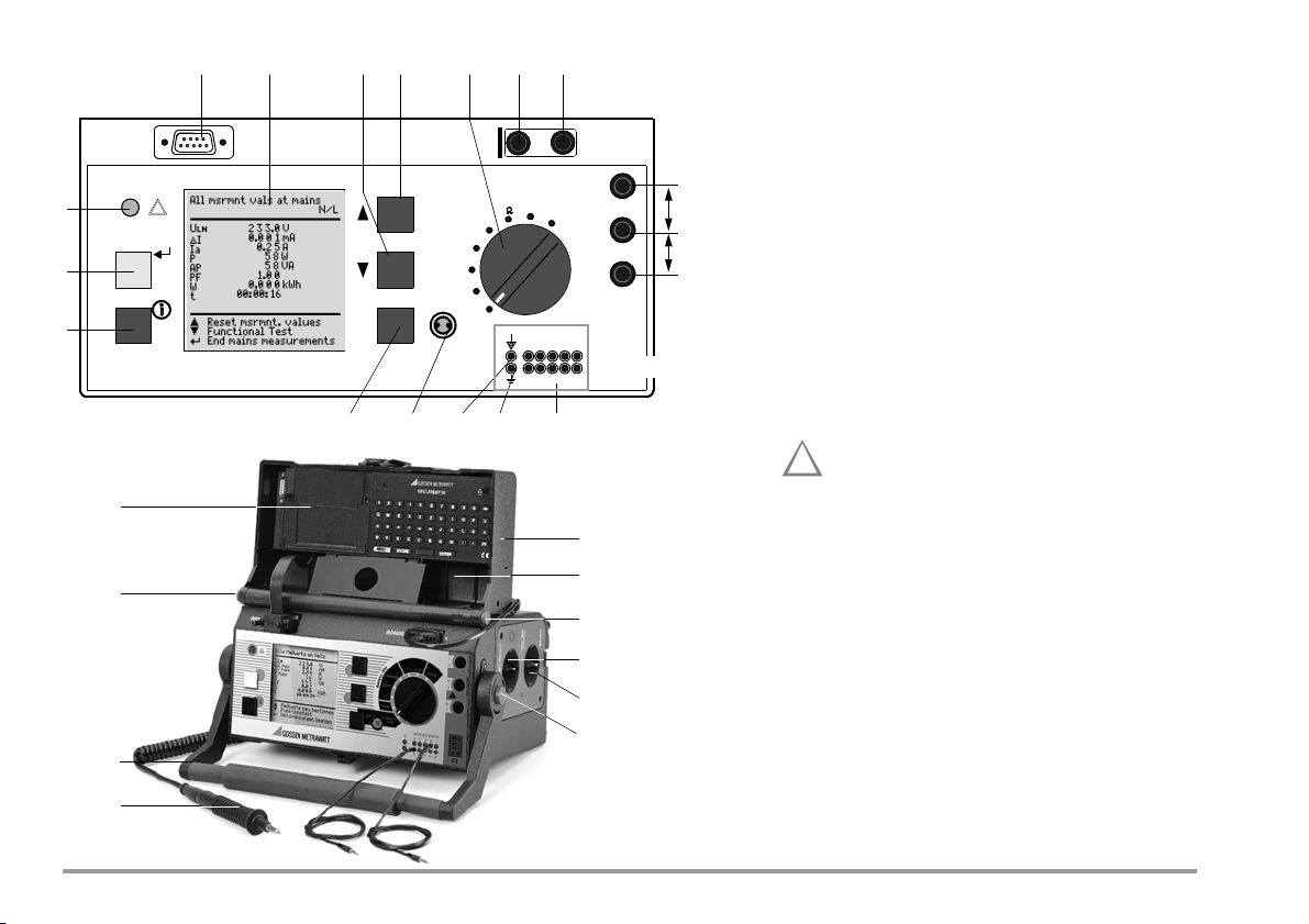
45678910
!
24
23
22
21
25
22
26
27
20
19
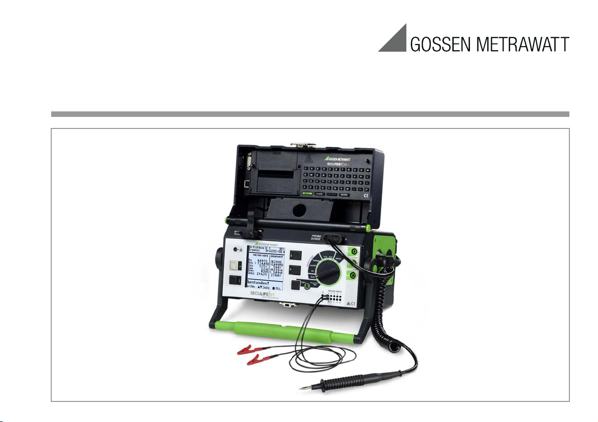
Probe connection
Insert the double plug of the probe into sockets 4 and
5 such that the plug with the white ring contacts
socket 5 (vertical bar).
Note: Contact problems with exposed conductive parts
when using the standard probe with test tip
In order to assure good contact, surface coatings must be
removed from devices under test with special tools at a suitable location so that the surface has a metallic shine. The tip
of the test probe is not suitable for scratching away paint, because this may impair its coating and/or mechanical
strength. The brush probe (Z745G) may be more suitable
than the test probe in certain individual cases.
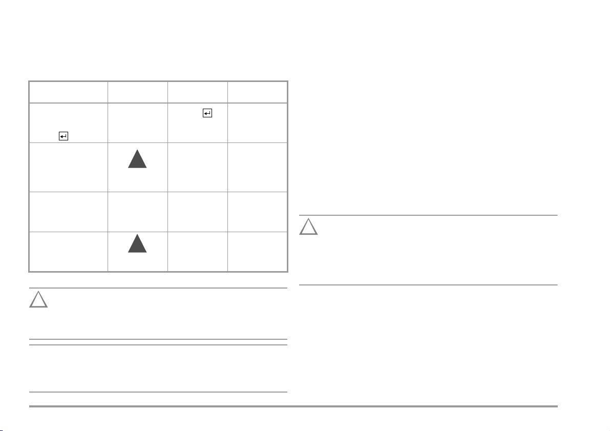
Measurements at jacks 1 – 2 – 3
Always start with the measurement before contacting
the measuring point. Between jacks 1 and 2, a maxi-
11
12
13
RS232
IOIOI
PROBE
54
SONDE
Setup
3
2
1
HV
Function
Test
V
Aux
Applied Parts
AC E G I
BDFHK
!
Iso
I leakage
/
PE
Auto
L
3
max. 253 V
N
2
max. 10 V
SL
1
mum of 10 V may be applied. Between jacks 2 and 3,
14 15 1816 17
up to 253 V may be applied.
Attention: Jacks (2) and (3) are short-circuited
during all measurements at the test socket!
(Exception: see chapter 12.2)
Standard equipment
1
Test instrument with 10 + 2 connectors for application parts
1 Probe cable with test probe
1 Clip-on alligator clip for test probes
3 Clip-on quick-clamp terminals
10 conductor patient connection cable 2 mm
10 Clip-on alligator clip 2 mm
1 Calibration certificate per DKD
1 Operating instructions
1Carrying strap
Up-to-date PC software (free start-up programs or
demo software for data management, report and list
generation) is available on our website for download.
These operating instructions describe an
instrument with firmware version 7.24.
2 GMC-I Messtechnik GmbH
Page 3
1 Jack for protective conductor at device under test
Note
i
!
2 Jack for neutral conductor at device under test
3 Jack for phase conductor at device under test
4 Jack for connecting the probe
5 Jack for connecting the probe
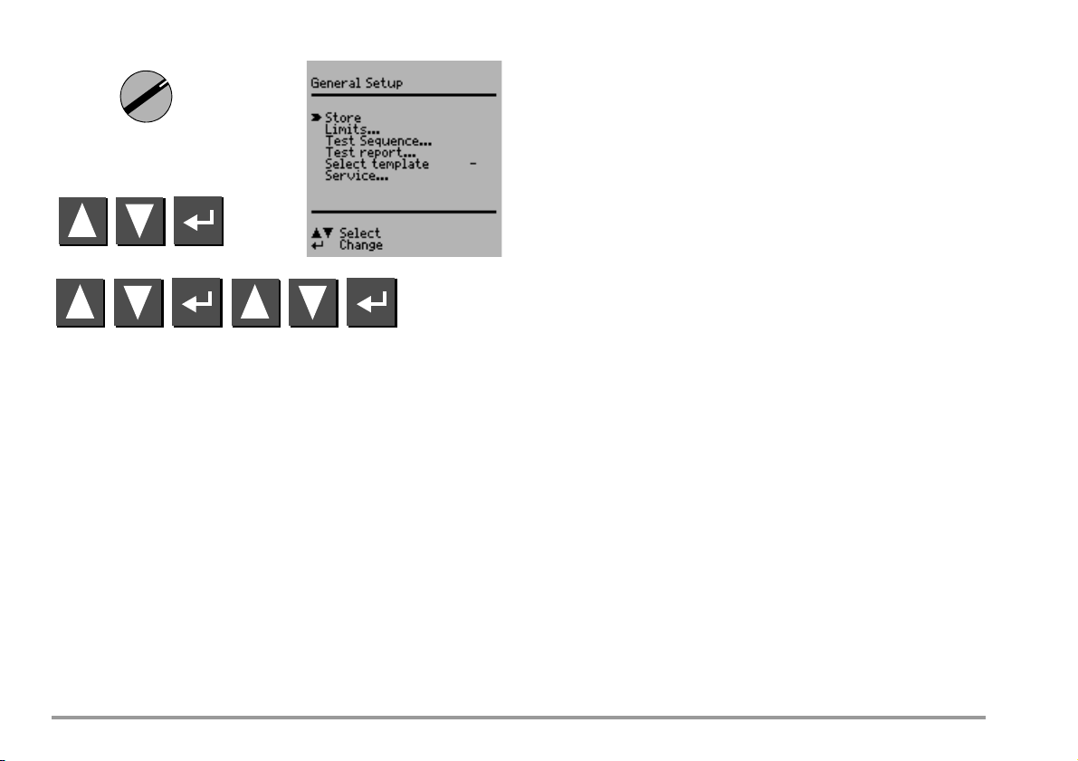
6 Function selector switch
– Function Test: Function test
– Auto: Automatic test sequence according to selected standard
– PE: Protective conductor test
– Iso/HV: Insulation test / high-voltage test
– I leakage: Leakage current measurement
– V : Multimeter functions
– Aux: Auxiliary multimeter functions
– Setup: Device configuration
7 scroll key for menu and parameter selection
8 scroll key for menu and parameter selection
9 LCD window
10 Socket connector interface RS232 for (P)SI module SECUTEST PSI/SI+, storage
adapter
SECUSTORE
, barcode or RFID scanner
11 Signal lamp for mains connection error
12 key for entry and for starting test sequences and finger contact
13 help key (context sensitive)
14 Key next to the symbol for switching test voltage to
the test socket (only possible if symbol LED is blinking)
15 Signal lamp for the functions test
16 Functional earth (equipotential bonding)
17 Operational earth
18 Connector jacks for application parts
19 Push-buttons (left and right) for releasing the handle from its snap-in position
20 Earthing contact socket for service purposes (Feature B01),
e.g. for connecting a notebook or an A4 format printer, Terminal Data see page 63
21 Standard outlet socket (test socket) for connecting the device under test
22 Push-buttons (left and right) for releasing the lid
23 Lid
24 Compartment for probe and accessories
25 Cover or (P)SI module (accessory
SECUTEST PS I or SECUTEST SI+)
26 Carrying handle and tilt stand
27 Test probe (accessory probe with coil-cable SK2W (Z745N))
Overview of Available Probe Types
Probe Type Application Special Features
Standard probe (test probe with
coil-cable and alligator clip)
1)
SK2
1)
SK2W
Feature KD01 with probe SK5 Restriction with
Brush probe
Can be plugged onto all above
listed probes and test probes
1)
1)
Accessory
Max. test current: 25 A Probe with cable
Max. test current: 25 A Probe with cable (no coil-cable),
Max. test current: 25 A Probe with cable (coil-cable),
Feature G01 (I
short-circuit current < 25 A
Leakage current,
protective conductor resistance
>25A):
K
(no coil-cable)
2 meters long
2 meters long
Special probe in combination with
“automatic recognition of measuring point change” function (see
chapter 17)
For contacting devices under test
with rotating, vibrating, exposed
conductive parts
when using other probes than those specified above
The cables plugged into the sockets (4 and 5) must be short
circuited for testing with the probe, i.e. by plugging the ends of
the cable together, or via a conductive surface at the device
under test (4-wire measurement).
Remove any corrosion from the device under test.
Data Security
Measurement data, report data and user entries are stored to RAM at the
(P)SI module (accessory), as long as the respective battery supplies the
required amount of voltage.
Save your data to a PC on a regular basis in order to prevent any loss of data
at the (P)SI module. We assume no liability for data loss. We recommend the
following PC programs for data processing and data management:
• PS3 (transmission of measurement data to a PC, documentation,
management, report generating and deadline follow-up)
• PC.doc-WORD/EXCEL (report and list generation
• PC.doc-ACCESS (test data management)
• ELEKTROmanager/PROTOKOLLmanager for SECUTEST...
• patManager (Report and list generation)
GMC-I Messtechnik GmbH 3
Page 4

Contents Page Contents Page
1 Applications ...................................................................................6
8 Configuring Device Parameters ...................................................18
1.1 Table: Types of DUTs – Tests – Regulations .............................................. 6
1.2 Table: Individual Measurements and Regulations .....................................7
1.3 Table: Leakage Current Types ...................................................................7
1.4 List of Possible Options and Standard Types .............................................. 8
9 Measuring Protective Conductor Resistance ...............................19
9.1 Maximum Allowable Limit Values for Protective Conductor Resistance
for Connector Cables with a Length of up to 5 m ..................................... 20
2 Safety Features and Precautions ...................................................9
2.1 Notes Regarding the High-Voltage Test
(only Feature F02 or SECULIFE ST
HV) .......................................................10
3 Initial Start-Up ..............................................................................11
3.1 Connection to the Mains (115 V / 230 V, 50 Hz / 60 Hz) ............................11
3.2 Automatic Recognition of Mains Connection Errors ..................................12
4 General Notes ..............................................................................12
4.1 Online Instructions ....................................................................................12
4.1.1 Changing the User Interface Language .........................................................12
4.1.2 Automatic Safety Class Selection ..................................................................13
4.1.3 Manual or Automatic Operating Sequences ...................................................13
4.2 Online Help ................................................................................................13
4.3 Adjusting Contrast .....................................................................................13
4.4 Configuring Device Parameters, Setting Date and Time ...........................14
4.5 Configuring Measurement and Sequence Parameters .............................14
4.6 Setting Limit Values ..................................................................................14
4.7 Saving the Settings ...................................................................................14
5 Classification of Devices Under Test ............................................15
5.1 Safety Classes ...........................................................................................15
5.2 Application Parts (electrical medical devices) ..........................................15
6 Abbreviations ...............................................................................16
7 Connecting the Device Under Test ...............................................17
10 Insulation Measurement .............................................................. 20
10.1 Insulation Resistance R
10.2 Equivalent Leakage Current ..................................................................... 22
10.3 High-Voltage Test (Feature F02 or SECULIFE ST
. ....................................................................... 20
INS
HV) ................................. 24
11 Leakage Current Measurement ...................................................26
11.1 Earth Leakage Current IPE (Feature KA01) ................................................ 26
11.2 Housing Leakage Current I
11.3 Patient Leakage Current I
11.4 Patient Auxiliary Current IPA (Feature KA01) ............................................. 27
11.5 Residual Current I
RC .......................................................................................................27
(probe current, contact current) ................. 26
HL
PL ......................................................................................... 27
11.6 Device Leakage Current ILC per IEC 62353 (VDE 0751-1) ......................... 27
12 Multimeter Functions ...................................................................30
12.1 Probe Voltage U
12.2 Alternating / Direct Voltage U
12.3 Resistance R ............................................................................................. 31
– Max. 300 V ........................................................... 30
probe
– Max. 253 V .....................................30
AC/DC
13 Measurements with Accessories .................................................32
13.1 Alternating Current IC with Clip-On Converter ..........................................32
13.2 Protective Conductor Resistance R
13.3 Temperature T with Pt100/1000 Sensor ................................................... 33
via Clip-On Meter ..........................32
PE
14 Function Test ...............................................................................34
4 GMC-I Messtechnik GmbH
Page 5

Contents Page Contents Page
15 Measurements in Accordance with National and
International Standards with Selector Switch in Auto Position ... 36
15.1 Test Sequences .........................................................................................36
15.2 Setting Up Test Sequences .......................................................................37
15.3 Configuring Measuring Parameters ..........................................................39
15.4 Testing Devices in Accordance with DIN VDE 0701, Part 1 .......................40
15.5 Testing Devices in Accordance with DIN VDE 0701, part 240 ...................42
15.6 Testing Devices in Accordance with DIN VDE 0701-0702:2008 ................44
15.7 Testing Extension Cables for VDE 0701-0702 (VDE 0701 Part 1)
(optional EL1 adapter) ...............................................................................46
15.8 Testing Multiple Outlets for VDE 0701-0702 (optional EL1 adapter) .........47
15.9 Testing in Accordance with DIN EN 60 950 ...............................................48
15.10 Testing Devices in Accordance with EN 61010 ........................................50
15.11 Testing Devices in Accordance with EN 60335 ........................................52
15.12 Testing in Accordance with IEC 62353/VDE 0751 .....................................54
15.13 Testing in Accordance with EN 60601 (Feature KA01) .............................56
16 Storing in (P)SI Module (Accessory) and Database Operations
(Feature KB01) ............................................................................. 58
16.1 Storing Measurement Data in the (P)SI Module ........................................58
16.2 Database Operations .................................................................................58
16.2.1 Storing Test Results to the Test Instrument ...................................................58
16.2.2 Uploading Report Templates into Test Instrument, Reading Out From the Test
Instrument, Editing at the PC and Re-Saving to the Test Instrument ................58
16.2.3 Reading Out and Saving Test Results / Test Data from the (P)SI Module ..........58
20 RS 232 Interface .......................................................................... 64
20.1 Transmission of Measurement Results to the (P)SI module .....................64
20.2 PC Connection ...........................................................................................64
20.2.1 Software Evaluation of Measurement Results ................................................64
20.2.2 Instrument Control via Interface Commands ..................................................64
20.3 Interface Definition and Protocol ..............................................................64
21 Appendix ..................................................................................... 65
21.1 Evaluation of Measured Values for Individual Measurements
as well as for Calculated Quantities .........................................................65
21.2 Evaluation of Measured Values during Equivalent Leakage Current
Measurement (Automatic Test Sequence According to Standard) ........... 65
21.3 Index ......................................................................................................... 66
22 Maintenance - Recalibration ....................................................... 68
22.1 Housing Maintenance ...............................................................................68
22.2 Recalibration ............................................................................................. 68
22.3 Safety Checks ...........................................................................................68
22.4 Device Return and Environmentally Compatible Disposal ........................69
23 Repair and Replacement Parts Service
Calibration Center and Rental Instrument Service ...................... 69
24 Product Support .......................................................................... 70
17 Recognition of Probe to Protective Conductor
(Feature KD01) ............................................................................. 58
18 Storing Test Results and Printing in Report Form ....................... 59
19 Characteristic Values ...................................................................60
GMC-I Messtechnik GmbH 5
Page 6
1 Applications
Attention!
!
1.1 Table: Types of DUTs – Tests – Regulations
Start-up and
Modifications
Devices under test
to be tested in
accordance with the
following regulations
EC 62353 :2007
I
Laboratory instruments
Measuring and control instruments
Voltage generation devices
Electric tools
Electric heating devices
Electric motor devices
Lamps
Devices for entertainment
electronics, information and
communications technology
Cable reel, extension and
connection leads
Data processing and office
equipment
Electrical medical devices,
application parts
Testing after
Repairs
-0702:2008
DIN VDE 0701
DIN EN 62353:2008
(VDE 0751-1)
Periodic
Tes t in g
-0702:2008
1
EC 62353 :2007
I
DIN VDE 070
DIN EN 62353:2008
Routine Testing
EC 62353 :2007
I
DIN EN 62353:2008
DIN EN 60950/50 116
DINEN61010
DIN EN 60335/50 106
IEC 60601/DIN EN 60601
The test instrument may not be used for measurements
within electrical systems!
Applicable Standards
German National European International
DIN EN 61010 EN 61010 IEC 61010
DIN EN 60601 EN 60601 IEC 60601
DIN EN 60335-1 EN 60335-1 IEC 60335-1
DIN EN 60950 EN 60950 IEC 60950
IEC 62353 :2007
DIN EN 62353:2008
EN 62353 IEC 62353
(VDE 0751-1)
6 GMC-I Messtechnik GmbH
Page 7
1.2 Table: Individual Measurements and Regulations
Individual Measurements
per Regulation
Tes t Cur re nt [ A]
DIN VDE 0701-0702
DIN VDE 0701
DIN VDE 0701
DIN VDE 0701
DINEN60950
DINEN61010
DINEN60335
IEC 62353
0.2
Protective Conductor
Resistance
Insulation Resistance
Equivalent Leakage Current
High-Voltage Test
Equivalent (Device) Leakage
Current
Equivalent Patient Leakage Current
Residual Current
Contact Current
Absence of Voltage
(exposed conductive parts)
Housing Leakage Current
Earth Leakage Current
Patient Leakage Current
Total Patient Leakage Current
Patient Auxiliary Current
Device Leakage Current
Single Fault Conditions N
PE
Mains at Application Part
10
25
AC AC
Key
Standards printed in grey half-tone will be superseded by the new
DIN VDE 0701-0702:2008 standard.
Required test
IEC 601/EN 60 601 2nd
IEC 601/EN 60 601 3rd
1.3 Table: Leakage Current Types
DIN VDE
0701-0702
Equivalent
Leakage Current
Contact Current/
Measurement for
Absence of
Volta ge
Protective
Conductor
Current with
Residual
Current
Measurement
IEC 62353
(VDE 0751-1)
Equivalent
Device Leakage
Current
Equivalent
Patient Leakage
Current
Housing Leakage
Patient Leakage
Current
NC
Device Leakage
Current during
Operation, Direct
Measurement
Device Leakage
Current during
Operation,
with residual
Current
Measurement
DIN EN 60601-1 The following is
IEL interrupted
from N
Current
NC
Patient Leakage
Current
NC
Patient Auxiliary
Current
NC
Earth Leakage
Current
NC
Key
NC = normal condition
PAP = patient application part
PE = Potential earthing
PC = Protective conductor of the DUT
, system protective conductor
measured:
PROBE
(connected to
protective
conductor)
to L & N
PROBE
(connected to
protective
conductor)
to L & N
L & N & PE to
Patient Jacks
Probe to PE
Patient Jack to PE
Patient Jack to
Patient Jack
Protective
Conductor to PE
Protective
Conductor
Interrupted, Probe
+ PAP to PE
See chapter 11.5
GMC-I Messtechnik GmbH 7
Page 8
1.4 List of Possible Options and Standard Types
Features 00 01 02 03 04 05 06 07 08 09 10 11 XX
Mains Connection for
Respective Country
User Interface Language C DUKF I ECZENL
High Voltage Testing
HV-DC F without
AC Test Current 50/60 Hz
for Protective Conductor
Measurement
Test Sequence
for IEC 60601
Data Memory
for up to 125 Tests
Recognition of
Probe to Protective Conductor
Direct Printing after each
Measurement for Automatic
Test Sequences
Read-Out via RS232
1)
Each measured value is documented in this case, as opposed to the results of a
test sequence for which only the poorest value for each given test is displayed.
(via the PSI module, the SECUSTORE storage adapter or a PC)
5)
1)
B D
G 10 A 25 A
KA without with
KB without with
KD without with
KE without with
D + ser-
vice socket
4)
UK
max.
6.126 kV DC
( 4KVAC)
F/CZE DK
2)
Adapter set for international use (comes with Feature B01)
4)
if adapter (feature B11) is applied: HV-DC max. 1.5 kV DC
5)
without function test values and without comments on DUT
4)
China/AUS
4)
CH
adapter
set 2)
4)
Designation Type
Test instrument with test current
200 mA DC and 10 A AC
Sequences for IEC 61010, IEC 60 335,
IEC 60950 and IEC 60601,
data memory for up to 125 tests
SECULIFE ST M693A
Same instrument as M693A, however,
suited to international use with adapter
set for mains connection in the respective
user country and English user interface
language SECULIFE ST M693B
8 GMC-I Messtechnik GmbH
Article Number
Designation Type
Same instrument as M693A, however, with
test current 200 mA DC and 25 A AC,
additionally with high-voltage test max.
6.126 kV DC ( 4 KV AC) SECULIFE ST
Same instrument as M693C, however,
suited to international use with adapter
set (application of adapter: high-voltage
test max. 1.5 kV DC) for mains connection
in the respective user country and English
user interface language SECULIFE ST
Article Number
HV M693C
HV M693D
Page 9
2 Safety Features and Precautions
Note
Attention!
!
This instrument fulfills the requirements of the applicable European and national EC guidelines. We confirm this with the CE marking. The relevant declaration of conformity can be obtained from GMC-I Messtechnik GmbH.
The test instrument has been manufactured and tested in accordance
with the following safety regulations:
IEC 61010-1 / DIN EN 61010-1 / VDE 0411-1, DIN VDE 0404, DIN VDE
0413 Part 2 and 4 and DIN VDE 0104 (Feature F02 or
Only when used for its intended purpose, the safety of the user, the test
instrument and the device under test (electrical equipment or electrical
medical devices) is assured.
Read the operating instructions carefully and completely before placing your test
instrument into service, and follow all instructions contained therein. Make sure
that the operating instructions are available to all users of the instrument.
Tests may only be performed by a qualified electrician or under the supervision of
a qualified electrician. The user must be instructed by a qualified electrician
concerning performance and evaluation of the test.
Manufacturers and importers of electrical medical devices must
provide documentation for the performance of maintenance by
trained personnel.
Observe the following safety precautions:
• The instrument may only be connected to electrical systems with a
maximum of 230 V +10% which are protected with a fuse or circuit
breaker with a maximum rating of 16 A.
• Measurements within electrical systems are prohibited.
• Be prepared for the occurrence of unexpected voltages at devices
under test (for example, capacitors can be dangerously charged).
• Make certain that the measurement cables are in flawless condition,
e.g. no damage to insulation, no interruptions in cables or plugs etc.
• When using a probe with coil cable (SK2W): Grip the test probe firmly,
for example after insertion into a jack socket. Tensioning at the coil
cord may otherwise cause the test probe to snap back resulting in
possible injury.
• Measurement of Insulation Resistance and Equivalent Leakage Current
This test is performed with a maximum voltage of 500 V, with a current
SECULIFE STHV)
limit having been set (I < 3.5 mA). However, contacting the terminals
(3 or 2) causes an electric shock which, in turn, may result in accidents.
• Leakage Current Measurement
During leakage current measurement it is imperative to ensure that the device under test is operated at line voltage. Exposed conductive parts may
be charged with hazardous contact voltage during the test and may consequently not be touched under any circumstances. (There is a power
shutdown as soon as the leakage current is higher than approx. 10 mA).
The function test may only be performed after the DUT has
successfully passed the safety test!
Switching loads on and off
When switching the DUT on or off under load it is imperative that you adhere to the order indicated below. This helps to prevent excessive wear
and tear of the mains relays at the test instrument.
Before the measurement:
1) DUT: Switch the DUT off at the proprietary switch.
2) SECULIFE ST or SECULIFE ST
3) DUT: Switch on the DUT at the proprietary switch.
After the measurement:
4) DUT: Switch the DUT off at the proprietary switch.
5) SECULIFE ST or SECULIFE ST
The measuring and test instrument may not be used:
• If it demonstrates visible damage
• With damaged connector cables, measuring cables or patient ports
• If it no longer functions properly
• After extraordinary stresses due to transport
In such cases, the instrument must be removed from operation and
secured against unintentional use.
HV:
Apply line voltage to the test socket .
HV:
Disconnect the test socket from the line .
GMC-I Messtechnik GmbH 9
Page 10
Meanings of Symbols on the Instrument
Attention!
!
!
The symbols on the instrument have the following meanings:
Warning regarding dangerous electrical voltage
Warning concerning a point of danger
(Attention: observe documentation!)
Test socket
Mark of approval from VDE test authority
Indicates EC conformity
This device may not be disposed of with the trash. For further
details on the WEEE marking, please refer to our website
www.gossenmetrawatt.com and enter search term ’WEEE’.
2.1 Notes Regarding the High-Voltage Test
(only Feature F02 or SECULIFE ST
The KS13 cable set, or similar cable sets, may not be used for the high-voltage
test. The high-voltage test may only be performed directly via the test socket!
Do not hold the device under test in your hand during testing,
especially when testing safety class II devices.
Make sure that the device under test does not make contact
with any equipment or persons during testing.
Liability Exclusion
In the event of sparkover, PCs operated in proximity to the test instrument may
“crash” resulting in data loss. All data and programs should be suitably backed up
before high-voltage testing is performed, and computers should be shut down if
necessary. A crash may occur even if no RS 232 connection has been established.
The manufacturer of the test instrument assumes no liability for direct or
consequential damage to computers, peripherals or data which occurs
during high-voltage testing.
The manufacturer assumes no liability for defects at the device under test
which result from high-voltage testing. As a rule, defects can only occur at
devices under test which are not in compliance with applicable standards,
which were previously damaged or which have been improperly repaired,
because high-voltage testing is required for type and routine testing by
IEC 61010-1/EN 61010-1 / VDE 0411, part 1, as well as EN 60 335,
EN 60601 and EN 60950.
HV)
10 GMC-I Messtechnik GmbH
Page 11

3 Initial Start-Up
Attention!
!
L1
N
green-yellow
green-yellow
PE
L1
L2
L3
N
PE
L1
L2
L3
N
green-yellow
U
L–N
= 115 V / 230 V
Connection to the Mains
3.1 Connection to the Mains (115 V / 230 V, 50 Hz / 60 Hz)
õ Connect the mains plug at the test instrument to the mains power out-
let. The function selector switch can be set to any position.
If a mains outlet (earthing contact outlet) is not available, or if only a
3-phase outlet is available, the adapter socket can be used to connect
the phase conductor, the neutral conductor and the protective conductor. The adapter socket has three permanently attached cables
and is included with the KS13 cable set.
If connection is not possible via an earthing contact outlet: Shut
down mains power first.
Then connect the cables from the coupling socket to the mains
using pick-off clips in accordance with the diagram.
Disconnection from mains power is only possible with the mains
plug.
GMC-I Messtechnik GmbH 11
Page 12
3.2 Automatic Recognition of Mains Connection Errors
Attention!
!
Note
Attention!
!
!
!
The test instrument automatically recognizes mains connection errors,
if the conditions in the following table have been fulfilled. The user is
informed of the type of error, and all measuring functions are disabled
in the event of danger.
Typ e of Ma ins
Connection Error
Voltage at protective
conductor PE to finger
contact
(key)
Protective conductor PE
and phase conductor L
reversed and/or
neutral conductor N
interrupted
Contact voltage at
protective conductor PE
to neutral conductor N
or phase conductor L
Mains voltage
too low lamp
1)
In SETUP – test sequence – IT system
In either of the first two cases listed in the table above,
immediately disconnect the test instrument from the mains
and eliminate the error!
Message Condition Measurements
Text appears at
LCD
lamp
lights up
Text appears at
LCD
lights up
Press
key
U 40 V
Voltage at PE
>65V
U 25 V
U
< 90/180 V
L-N
disabled
impossible
(no supply power)
disabled, although
disabling can be
deactivated
possible
under certain
circumstances
4 General Notes
4.1 Online Instructions
Integrated online instructions inform the operator regarding all required
connections, necessary work steps, operator errors, measurement results
and more in all measuring modes.
Information and test results appear at the dot matrix LCD in clear text.
4.1.1 Changing the User Interface Language
If you require a different language for the user interface of the test instrument, you can load it into your test instrument by means of the update
and options installation program „SECU-Up“. The program is available for
download from our website www.gossenmetrawatt.com (Products >
Software > Software for Testers > SECU-Up).
Upon installation on your PC and starting the program, you proceed by
selecting the „Update“ menu and choosing a language from the following
list:
Deutsch, English, Français, Italiano, .
Only one language at a time can be installed on the test instrument, the
one previously installed is overwritten in the process.
1)
During data transmission, the test instrument and PC may not
be disconnected from the mains power supply under any circumstances.
No other programs under WINDOWS may be activated during
the update.
Voltage at the electrical system’s protective conductor PE may
result in distorted measurement values during testing for the
absence of voltage, or during leakage voltage measurements.
12 GMC-I Messtechnik GmbH
Page 13
4.1.2 Automatic Safety Class Selection
Note
Auto
Depending upon the type of mains plug or the connection configuration
for the device under test, the test instrument recognizes the respective
safety class and recommends its use for the measurement to be performed.
4.1.3 Manual or Automatic Operating Sequences
Depending upon selections made in the setup menu (selector switch in
the Auto position), the next measurement is started automatically after the
current measurement has been completed, or can only be started after
manual acknowledgement. The integrated online instructions are adequate for most tests and measurements. However, the contents of these
operating instructions should nevertheless be read and observed.
4.2 Online Help
Online help can be queried and displayed at the LCD for all measuring
and test functions, and for almost all settings. Schematic diagrams which
illustrate proper connection of devices under test to the test instrument
can be displayed as well.
õ Press the following key in order to query online help:
4.3 Adjusting Contrast
Set the selector switch to Auto.
Select the “Setup” menu, “return” is highlighted.
Activate contrast adjustment.
Press and hold the ENTER key.
õ Press the same key again in order to exit online help.
Adjust contrast.
Online help can be queried during measurement by pressing
and holding the help key.
Return to the menu.
Store the contrast setting to permanent memory with the save function in
the setup menu.
GMC-I Messtechnik GmbH 13
Page 14

4.4 Configuring Device Parameters, Setting Date and Time
Device parameters and functions which are valid for all selector switch
positions can be activated or deactivated with the selector switch in the
Setup position (see chapter 8 on page 18).
4.5 Configuring Measurement and Sequence Parameters
Measurement and sequence parameters, as well as functions, can be
activated or deactivated in the setup menu (selector switch in the Auto
position) for the respective test regulation. Refer to chapter 15.3 on page
39 for the significance of the various parameters.
4.6 Setting Limit Values
Upon delivery, the limit values set forth (at the point in time of issue) in applicable national and international standards are stored to the test instrument. Limit values for each of the respective standards can be queried
and changed if required with the setup menu (selector switch in the Auto
position), but changes can only be made which result in even stricter testing than is required by the respective standard.
Newly entered limit values become effective immediately. However, these
are only stored to memory permanently after activating the store function
in the setup menu.
If the limit values set forth in the standards for certain safety classes need
to be restored despite individualized settings, the menu function all values
per standard in the limit values sub-menu must be selected and acknowledged with the key.
If the limit values set forth in the standards are changed, the instrument’s
device software can be updated via the RS 232 interface.
4.7 Saving the Settings
All of the settings and changes which have been entered to the configure,
limit values (selector switch in the Auto position) and zero point (temperature
measurement) (selector switch in the Aux position) menus, as well as the se-
lected contrast setting are retained until the selector switch is turned, or
the test instrument is disconnected from mains power. If settings and
changes should be retained even after mains power has been interrupted,
they must be saved in the setup menu for the respective test regulation or
selector switch position.
14 GMC-I Messtechnik GmbH
Page 15
5 Classification of Devices Under Test
5.1 Safety Classes
Devices assigned to all of the following safety classes are equipped with
basic insulation, and provide for protection against electrical shock by
means of various additional precautions as well.
Safety Class I Devices
Exposed, conductive parts are connected to the protective conductor so
that they are not charged with voltage if the basic insulation should fail.
5.2 Application Parts (electrical medical devices)
Type B Application Parts (body)
Devices of this type are suitable for both internal and external patient
applications, except for use in direct proximity to the heart.
These devices provide for adequate protection against shock especially
as regards:
• Reliable leakage current
• Reliable protective conductor connection if utilized
Devices of the following safety classes are allowable:
I, II, III or devices with internal electrical power supply.
Safety Class II Devices
These devices are equipped with double insulation or reinforced insulation.
Safety Class III Devices
and Devices with Internal Power Supply
These devices are powered with Safety Extra Low Voltage (SELV). Beyond
this, no voltages are generated which exceed SELV. These devices may
not be connected to the mains. They may only be connected to the test
instrument at jacks 1 through 3.
Type BF Application Parts (body float)
Same as type B, but with type F insulated application parts.
Type CF Application Parts (cardiac float)
Devices of this type are suitable for use directly at the heart. The application part may not be grounded.
Devices of the following safety classes are allowable:
I, II or devices with internal electrical power supply.
Note: The DUT may only be connected to jacks 1 to 3 at the test instrument. It is only possible to perform a visual inspection, a measurement of
the insulation resistance or the supply voltage, see parameter “SC II I U
on page 39.
”
V
Classification Parameter (in the Sequence ... menu)
The test instrument always performs testing in accordance with the strictest limit values of the respectively selected safety class. The test is failed if
this limit value is exceeded.
However, higher limit values are allowed for certain devices under test.
If the classification parameter has been activated (= x), the user is asked if
higher limit values are allowable for these devices. If the user responds
with “Yes”, the DUT is reevaluated and the test may be passed.
Devices with Internal Power Supply
Devices with internal power supply are tested like permanently connected
Safety Class II or II I devices.
GMC-I Messtechnik GmbH 15
Page 16

6 Abbreviations
AE Error condition: application part grounded
AP Apparent power (during function test)
B, BF, CF Classifications for application parts
DEFI Defibrillator
I Residual current, fault current (during function test)
I
max
RC
wc
HE Error condition: housing grounded
I
CLIP
I-EHC
SCII
I-EHL
A1/A2
I-EHL
FRPE
IEL, I-EL Equivalent leakage current
, I-EDL
I
EDL
I
, I-EPL Equivalent patient leakage current
EPL
, IHL, I-HL Leakage current (differential, probe or contact current)
I
L
(Ia) (Maximum) load current (during function test)
I
L(max)
I
LC
I
PA
I
PE
I
PL
I
PMAP
IRC, (IRe) Residual current (current at protective conductor during
, I-HL Contact current (housing leakage current)
I
C, IHL
IT-system The IT system makes no direct contact between active
L Phase conductor connection of DUT
MedGV German medical device ordinance
Maximum residual current (during function test)
Residual current worst case
Current at clip-on meter
Equivalent device leakage current for devices with
additional safety class II components
Equivalent device leakage current with note A1/A2
(cross-reference within the standard)
Equivalent device leakage current for portable x-ray devices
+PE: with additional protective conductor
–PE: without additional protective conductor
Equivalent device leakage current (current at protective conductor)
Device leakage current
Patient auxiliary current
Earth leakage current (current at protective conductor)
Patient leakage current
Mains to application part (patient leakage current measurement)
automatic test sequence)
conductors and grounded parts: bodies within the electrical system are grounded.
MSELV Medical safety extra-low voltage
N Neutral conductor connection of DUT
NC Normal condition
OE Operational earth
P Active power (during function test)
PA Functional earth (equipotential bonding)
PE Protective conductor connection of DUT
PF Power factor (during function test)
RResistance
, R-INS Insulation resistance
R
INS
R-INS AP-PE Insulation resistance: application part to PE
R-INS
INT. KARD.
Insulation resistance: intercardiac
(application in proximity to the heart)
R-INS NL-PE Insulation resistance: neutral/phase conductor to PE
, R-PE Protective conductor resistance
R
PE
R-PEmains Protective conductor resistance limit value for
+mains: device under test with mains cable
–mains: device under test without mains cable
(protective conductor resistance limit value for mains
cable only = 0.1
SELV Safety extra-low voltage
SFC Single-fault condition
t On-time (during function test)
T, Temp Te mper a tur e
U
AC/DC
U
REF
, U-HV High-voltage
U
HV
, U-INS Test voltage for insulation measurement
U
INS
, U-LN Line voltage
U
LN
U
MEAS
U
Probe
AC/DC voltage
Reference voltage: voltage to which leakage current is
related (as a rule nominal line voltage)
Voltage at which testing was executed.
Displayed for all leakage current measurements.
Probe voltage
W Electrical energy (during function test)
ZVEH General Association of German Electricians
MLV manufacturer’s limit value
MPG German medical product law
16 GMC-I Messtechnik GmbH
Page 17
7 Connecting the Device Under Test
Note
Note
Attention!
!
Attention!
!
Attention!
!
õ Connect the DUT in accordance with the schematic diagrams included
in the online help function.
Connection of the DUT to the test instrument depends upon:
• The type of device under test:
electrical equipment or not, with or without application parts
• The type of connector included with the DUT:
– With plug (“to test socket” parameter), applies to EL1 adapter as well
– Without plug, single or multi-phase connection (“to jacks” parameter)
– No connection to tester (“permanent connection” parameter),
see also chapter 3.1
Whether or not an adapter is used:
– Adapter to socket (customer specific adapter)
– AT3-II S to socket, adapter for devices which are equipped with
5-pole, 16 A CEE plugs
– AT3-III E to socket, adapter for devices which are equipped with
5-pole, 32 A CEE plugs, see AT3-III operating instructions for test
sequence.
• The DUT’s safety class (I, II or III)
The DUT must be switched on for all tests. Switches, relays,
temperature regulators etc. must all be taken into consideration.
The test instrument automatically recognizes whether or not the DUT is
connected to jacks 1 through 3. The instrument also recognizes whether
or not the DUT has been connected to the test socket. As a default setting, the program sequence assumes that the plug from the DUT has
been connected to the test socket.
õ Position the cursor at the third line in the start menu for the test se-
quence.
õ A selection of possible connection setups can be displayed by
activating the key.
õ Select the desired connection setup with the cursor and
acknowledge with the key.
For omitting the protective conducter test in the case of fully insulated devices see
page 65.
Protective Conductor and Insulation Resistance Measurements for Permanently
Installed Devices Under Test
Deactivate the electrical system which supplies power to the
device under test before connecting the test instrument!
õ Remove the mains fuses from the device under test and disconnect
the neutral conductor N inside the device under test.
Measuring Contact Current (absence of voltage)
Make sure that the contacted parts are not grounded.
High-Voltage Test (Feature F02 or SECULIFE ST
The KS13 cable set, or similar cable sets, may not be used
for the high-voltage test. The high-voltage test may only be
performed directly via the test socket!
HV)
Safety Class II Devices with Safety Class I Mains Plugs
If the device under test is equipped with a safety class I plug
although it complies with safety class II, safety class I is recognized by the test instrument. If this is the case, switch from safety
class I to safety class II in the initial menu.
If the test instrument is unable to automatically recognize how the DUT
has been connected, the recommended connection setup should be
double checked and determined manually if necessary.
GMC-I Messtechnik GmbH 17
õ Connect the device under test to the test socket.
õ Safety class II only: Connect the probe to jacks 4 and 5.
Make sure that the application parts are not connected during
the high-voltage test!
Page 18
8 Configuring Device Parameters
Setup
duration selected in seconds under “Mains pause”
has elapsed.
Automode x: for fully automatic test sequences the messeges
are mainly suppressed
Test Sequence ...
General device parameters can be
configured and saved with the selector
switch in the Setup position.
Settings x / – = function activated / deactivated
Single-fault
If the single-fault condition has been activated, the test
is interrupted as a failure as soon as an error occurs.
Auto Class PSI Test results (passed or failed) for the various selector
switch positions are automatically assigned to the 8
statistics channels.
inc. Service Error Measurement results are compensated by taking
Select a menu and acknowledge.
IT Network Testing in IT systems can be performed by suppress-
service error into consideration (measuring error).
ing tests for U
whether or not voltage is present at PE.
PE-N
. The U
test determines
PE-N
(Leakage current measurement results may other-
Select parameter and acknowledge, change setting and acknowledge.
Limit values ...
Settings x / – = function activated / deactivated
Illumination Background illumination for the LCD. One of three
different conditions can be selected with the up and
down scroll keys: x: continuously on, –: off
Acst Sig, Seq
Acst Sig, Meas Acoustic signal is generated for: Measured value
Auto meas. point Prerequisite: Feature KD01. An acoustic signal indi-
numbers 1 through 9: duration in minutes after which
illumination is automatically deactivated.
Test time Duration of a single test (0 255 s)
Reference voltage: Voltage to which leakage current makes reference
(as a rule nominal line voltage)
Earth fault: During the short-circuit test, testing is also performed
to determine whether or not a connection exists
Direct Print-Out
Reports Reports which have been saved to memory can be
between L/N and PE (short-circuit to exposed conductive part). We assume that a short-circuit to an
exposed conductive part exists in the event of leakage current greater than 15 mA from L/N to PE. This
value should be increased for some DUTs (in particu-
Select template a report template can be selected for print-out from
Service – Time and date settings
lar high-current consumers), because greater leakage currents are present.
Mains wait Line voltage is first applied to the test socket.
18 GMC-I Messtechnik GmbH
However, testing does not begin until after the
wise be distorted.)
Acoustic signal is generated for: Incorrect connection of the
DUT, error in the electrical supply system, next test step.
fluctuations, test current polarity reversal
cates whether or not the probe is connected to the
protective conductor. The test sequence is run automatically.
Rapid signal frequency: probe connected to PE
Slow signal frequency: next measuring point
Prerequisite: Feature KE01, see chapter 18 on page 59.
selected from a list with an ID number and displayed
(see chapter 18 on page 59).
of 5 different templates.
(if a (P)SI module is used, the same time and date
must also be entered to the (P)SI menu)
– Service functions (password required)
Page 19
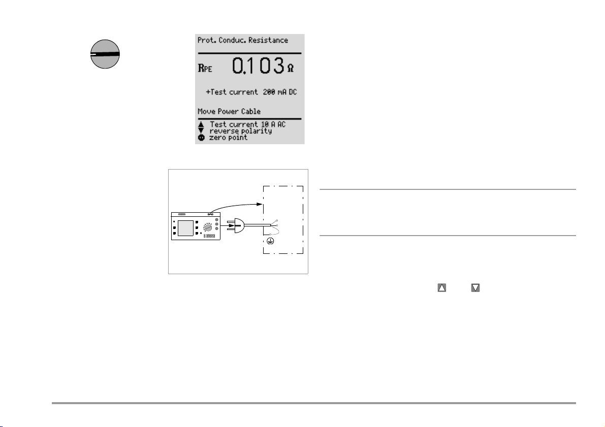
9 Measuring Protective Conductor Resistance
Note
PE
Connecting Safety Class I Devices to the Test Socket
When the DUT is connected, resistance is measured between the protective conductor terminal at the test socket or at the PE jack and the probe
connection at the DUT (contact with conductive parts of the housing).
õ In order to measure protective conductor resistance, contact a
conductive part of the housing with the probe, which is connected to
the protective conductor.
During measurement, the connector cable must only be moved in as far as
it is accessible during repair, modification or testing.
If a change in resistance occurs during the manual test step of the continuity test, it must be assumed that the protective conductor is damaged,
or that one of the connector contacts is no longer in flawless condition.
Definition
Protective conductor resistance
Testing Extension Cables
See test sequence in chapter 15.7 on page 46.
is the sum of the following
resistances:
• Connector cable or device
connector cable resistance
• Contact resistance at plug
and terminal connections
“Connection of the DUT: SC I/II” is not displayed when the test is
performed individually, but rather only during the automatic test
sequence.
• Extension cable resistance if
utilized
Resistance is measured:
• Between each conductive
part of the housing and the earthing contacts at the mains and the de-
vice plug (if a removable mains connector cable is used), or the protec-
Selecting Test Current and Polarity
Test current amperage (200 mA DC or 10 A AC (Feature G00 or SECULIFE ST) or
200 mA DC, 25 A AC (Feature G01 or SECULIFE ST
HV)) as well as polarity can
both be changed by pressing the or the key.
tive conductor terminal for permanently installed devices.
• as 4-pole measurement
• Between the earthing contacts at the mains plug and the earthing
contacts at the device plug for device connector cables
• Between the earthing contacts at the mains plug and the earthing
contacts at the coupling socket for extension cables
Testing with 10 A Test Current (Feature G00 or SECULIFE ST)
or 25 A (Feature G01 or SECULIFE ST
HV)
The test has a maximum duration of 30 s (fixed value) if 10 A or 25 A test
current is used. After this time period has elapsed, the last measured
value is frozen and “data hold, measurement stopped” appears at the display. If the test instrument becomes excessively warm, testing cannot be
repeated until after a waiting period of 1 minute. When testing with 10 A or
GMC-I Messtechnik GmbH 19
25 A, the last measurement can be repeated if the test results in failure.
Page 20

Combined Testing – Differential Protective Conductor Resistance
Iso / HV
f
o
r
S
C
I
I
Zero balancing is also possible for protective conductor measurement. With
zero balancing, all subsequent measurements are adjusted with an offset
such that 0 is displayed for a selected reference point which is connected to the protective conductor. When test points are contacted with
the probe which are electrically connected to this reference point, differential resistance R
point is displayed. The mains release key must be activated during
measurement in order to perform zero balancing. Press key
between the reference point and the contacted test
PE
„Store
value“ in order to save the reference and/or correction value. The meassage „Zero point corrected“ concerning the reference value is displayed
during all future measurements.
Attention: It is absolutely essential to delete the reference value after the
reference value has been stored and the test has been performed as it is
taken into account in all future tests. To delete the value, the procedure is
the same as for storage, press key
„Delete value“.
9.1 Maximum Allowable Limit Values for Protective Conductor Resistance for Connector Cables with a Length of up to 5 m
R
PE
Housing –
Device Plug
0.2 0.3
0.2 0.2
3)
Open-Circuit
Voltage
< 24 V
4 V < U
L
Tes t Sta nd ard Te st C urre nt
VDE 07010702:2008
IEC 62353
(VDE 0751-1)
EN 61010
EN 60335
EN 60950
EN 60601 0.1 0.2
1)
This value may not exceed 1 for permanently connected data processing
systems (DIN VDE 0701-702, DIN VDE 0701, part 240).
2)
Permanently connected cable
3)
Feature G00 = 10 A (SECULIFE ST) / G01 = 25 A (SECULIFE ST HV)
> 200 mA
10 A
~/25 A
to test socket
only
R
PE
Housing –
Mains Plug
1)
0.3
2)
+ 0.1
additional 7.5 m
2)
10 Insulation Measurement
10.1 Insulation Resistance R
Definition
Safety Class I
Insulation resistance is
measured between shortcircuited mains terminals and
the protective conductor.
Safety Classes II and I II
Insulation resistance is
measured between shortcircuited mains terminals and
external conductive parts
which can be contacted with
the probe.
INS
.
20 GMC-I Messtechnik GmbH
Page 21
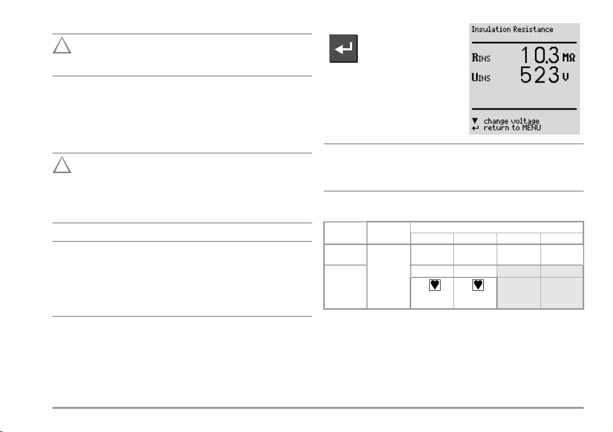
Exception for Permanently Installed Safety Class I Devices
Attention!
!
Attention!
!
Note
Note
Deactivate the electrical system which supplies power to the
device under test before connecting the test instrument!
õ Remove the mains fuses from the device under test and disconnect
the neutral conductor N inside the device under test.
õ Connect the probe to phase conductor L at the device under test in
order to measure insulation resistance.
Sequence
Measurement of Insulation Resistance (equivalent leakage current)
This test is performed with a maximum voltage of 500 V, with a
current limit having been set (I < 3.5 mA). However, contacting
the terminals (3 or 2) causes an electric shock which, in turn,
may result in accidents.
All switches at the device under test must be set to the ON
position during measurement of insulation resistance. This also
applies to temperature controlled switches and temperature
regulators.
Measurement must be performed in all program stages for
devices equipped with program controllers.
R-INS
Start measurement.
Nominal voltage is 500 V DC in this
case.
Nominal voltage can be adjusted within
a range of 50 V to 550 V DC.
When insulation is first started from the menu, nominal voltage is
always set to 500 V. Open-circuit voltage is always greater than
nominal voltage.
Minimum Allowable Limit Values for Insulation Resistance
R
Tes t St anda rd Tes t Vo lta ge
VDE 07010702:2008
IEC 62353
(VDE 0751-1)
500 V
SCI SCII SCIII Heat
1M 2M 0,25 M 0.3 M
2M 7M
INS
70 M 70 M
* for Safety Class I devices with activated heating elements
Notes
All exposed, conductive parts of safety class II and III devices, as well as
of battery-powered devices must be scanned with the probe and insulation resistance and/or leakage current must be measured.
Batteries must be disconnected from their terminals during testing of battery powered devices.
*
GMC-I Messtechnik GmbH 21
Page 22
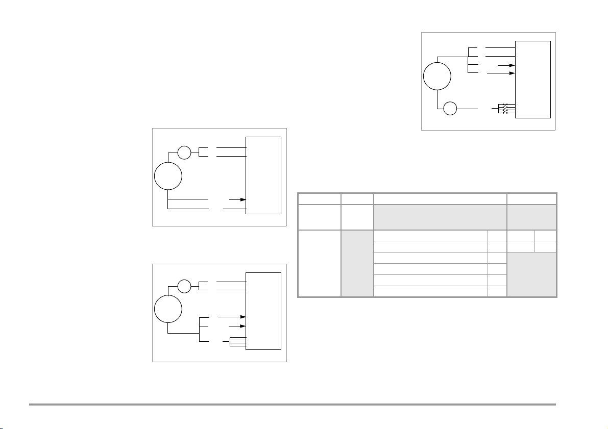
10.2 Equivalent Leakage Current
~
DUT
Probe
mA
PE
L
N
Probe
PAT
DUT
~
mA
L
N
PE
mA
Probe
PAT
DUT
L
N
~
PE
Equivalent Patient Leakage Current I
(IEC 62353 (VDE 0751-1))
EPL
Test S etu p
General
The equivalent leakage current measurement is a method for measuring
protective conductor current (DIN VDE 0701-0702) and/or device leakage
current (IEC 62353 (VDE 0751)).
A high-impedance power supply is connected between the short-circuited mains terminals and all exposed metal parts of the housing (which
are connected to one another).
Measurement of Equivalent Leakage Current I
per DIN VDE 0701-0702
EL
A high-impedance power supply
is connected between each patient port and all exposed metal
parts of the housing (which are
connected to one another). The
mains terminals are short-circuited, and connected to the
same point on the housing.
Measurement
The current which flows over the
insulation at the device under test is measured separately for each application part.
Measurement is always performed with an AC power supply with current
limiting. Varying line voltages are taken into account.
Maximum Allowable Limit Values for Equivalent Leakage Current in mA
Test Standard I
VDE 07010702:2008
Measurement of Equivalent Device Leakage Current I
(VDE 0751-1))
(per IEC 62353
EDL
IEC 62353
(VDE 0751-1)
The patient ports are linked with
each other and are connected to
the same point on the housing.
22 GMC-I Messtechnik GmbH
IELEquivalent leakage current
I
Equivalent device leakage current
EDL
I
Equivalent patient leakage current
EPL
PE Protective conductor
1)
for devices with heating power of 3.5 kW
2)
with and without line voltage applied to the application part
EL
SC I: 3.5
1 mA/kW
SC II: 0.5
1)
SC I (parts within or connected to PE)
Permanently connected devices with PE 10
Portable x-ray devices with additional PE 5
Portable x-ray devices without additional PE 2
I
EDL
SC II 0.2 Type BF 5
Devices with mineral insulation 5
1 Type CF 0.05
I
EPL
2)
2)
Page 23

Connection
Attention!
!
Refer to the schematic diagrams included with the online help for
connection instructions.
Equivalent Leakage Current I
DIN VDE 0701-0702 / 2 K
EL
Connection Exception for Permanently Installed Safety Class I Devices
Current is measured between the probe, with which the L and N conductors must be contacted, and the protective conductor terminal PE at the
device under test for permanently installed safety class I devices under
test.
Disconnect mains power before connecting the test instrument!
õ Remove the mains fuses from the device under test and disconnect
the neutral conductor N inside the device under test.
õ Connect the probe to phase conductor L and neutral conductor N at
the device under test in order to measure equivalent leakage current.
Sequence
Current is displayed during this type of equivalent leakage current
measurement which would flow during leakage current measurement
conducted in accordance with device regulations with nominal voltage.
Leakage current measurement in accordance with the respective device
regulations is usually not possible, because the device would have to be
set up in an electrically isolated fashion, or connected to an earth isolated
power supply to this end.
For the evaluation of measured values during equivalent leakage current
measurement please refer to chapter 21.2.
Select the I-EL measurement and start.
Equivalent leakage current is measured between short-circuited N and L,
and the protective conductor PE.
Measuring circuit resistance is equal to 2 k for VDE 0701-0702 for the
simulation of the mean body resistance of a human being.
Equivalent Device Leakage Current I
for IEC 62353 (VDE 0751-1) / 1 K
EDL
Select the I-EDL measurement and start
Equivalent device leakage current is measured between short-circuited N
and L, and the probe.
Measuring circuit resistance is equal to 1 k for IEC 62353/VDE 0751 for
the
simulation of mean patient resistance.
Equivalent Patient Leakage Current I
(IEC 62353 (VDE 0751-1))
EPL
Select the I-EPL measurement and start
Equivalent patient leakage current is measured between short-circuited N
and L and the respective application part. Jacks A through K (application
parts) are connected separately for each application part.
Groups of cables or sensors can be assigned to application parts in the
test sequence start menu in accordance with IEC 62353 (VDE 0751-1) or
EN 60601.
GMC-I Messtechnik GmbH 23
Page 24

10.3 High-Voltage Test (Feature F02 or SECULIFE ST HV)
Caution: High-Voltage!
Attention!
!
Only safety class I and II devices can be tested, which can be connected
to the test socket.
The high-voltage test is performed with direct voltage. In order to comply
with requirements for alternating voltage, testing is performed with 1.5fold direct voltage. This multiplier is applied automatically during testing. A
selected nominal voltage of 3.5 kV thus results in a DC output voltage of
5.25 kV.
Output voltage is measured for the entire duration of the test, and its minimum value is determined. The minimum voltage value is indicated as the
test result. If this value is less than the pre-selected test voltage, the test is
failed.
The conversion factor must be taken into consideration for testing and
calibration of the SECULIFE ST
HV.
The device is designed such that special measures in accordance with
DIN VDE 0104 (high-voltage test) need not be observed.
This is accomplished by means of the following characteristics:
1. Continuous short-circuit current is less than 3 mA (DC).
2. Discharge energy (at 5.25 kV) is less than 350 mJ.
In order to comply with high-voltage test regulations despite the minimal
continuous short-circuit current, the charging capacitors are connected to
the test socket (L, N) with relatively low-value protective resistors. This
results in a peak short-circuit current value of approximately 5 A (at 5 kV),
which causes plainly audible and visible sparking.
High-voltage testing can only be performed via the test socket. The protective conductor at the socket is grounded during the high-voltage test.
To uc h neither the test socket nor the device under test during
voltage testing!
A high-voltage of up to 5.5 kV is present at the test socket output!
A current may flow over your body, and although it does not
reach life endangering levels, the resulting shock is plainly
discernible.
Previous testing of the protective conductor is absolutely essential
for safety class I devices because if the protective conductor is in-
terrupted, the high-voltage test does not charge all dielectric material and the scope of testing is thus insufficient.
Connection
õ Insert the mains plug from the device under test into the test socket.
õ Safety class II: Connect the probe to jacks 4 and 5.
Make sure that the application parts (18) are not connected during high-voltage testing!
Individual Test
õ Set the rotary selector switch to the Iso/HV position.
õ Select the U-HV menu with the key and acknowledge with the
key.
õ If the device under test has not yet been switched on, a message to
this effect appears at the display. Nominal voltage is then selected.
õ Select the desired nominal voltage
from the display with the key.
The instrument multiplies this nominal voltage by a factor of 1.5, which
represents the actual test voltage
(see chapter 10.3).
Note: For SC I, the test voltage can
be set to maximum 1.5 kV.
õ Test voltage is applied to the test
socket, and in turn the device under
test, for as long as the
key is
held depressed. Activation of highvoltage is indicated with an acoustic
signal.
Currently measured minimum output voltage U
divided by 1.5), test voltage U
, and remaining test time are displayed.
DC
(measured value
HV AC
24 GMC-I Messtechnik GmbH
Page 25

õ Safety class II: Contact all exposed, conductive parts, simultaneously
Attention!
!
Note
if possible, in order to avoid unnecessarily long test durations or
repeats. Avoid contacting individual parts sequentially.
õ After the key is released, the equivalent AC voltage is displayed which
occurred during testing. This voltage is indicated as the test result. If
this value is less than the pre-selected nominal voltage, the test is
failed.
õ If you want to repeat the test, press the key. The test sequence is
started over again with selection of nominal voltage.
If sparkover should occur, the test is immediately interrupted
and the voltage measured at the moment sparkover occurred is
display as U
If the device is disconnected from the test socket during testing,
HV AC
.
even though this is prohibited, the test is immediately interrupted. The following message is displayed: “Caution, device
under test is still charged!”
Testing as Part of a Test Sequence
õ Select the high-voltage menu under the setup function for the respec-
tive test regulation in order to set parameters for the high-voltage test.
õ Enter the desired AC nominal voltages for safety classes I and II. The
instrument multiplies the respective AC nominal voltage by a factor of
1.5, which represents the actual DC test voltage (see chapter 10.3).
Test voltage is determined based upon the selected, or the automatically recognized safety class.
õ Save the setup values to memory.
õ Start the high-voltage test by pressing the key, if “manual
sequence” has been selected in the setup menu.
õ Safety class II only: Contact the device under test with the probe.
Activation of high-voltage is indicated with an acoustic signal.
The selected nominal voltage of 3.5 kV results in a DC output voltage of
maximum 5.25 kV.
The high-voltage test is ended auto-
matically after the test duration has
elapsed.
: Equivalent test voltage in DC
U
HV DC
U
: Measured DC value divided
HV AC
by 1.5
If the value U
lected nominal voltage U
failed.
is less than pre-se-
HV AC
AC
, the test is
In the event of sparkover, the
voltage measured at the moment sparkover occurred is displayed in the test results as minimum value U
reason the test was failed.
, along with the
HV AC
GMC-I Messtechnik GmbH 25
Page 26

11 Leakage Current Measurement
Attention!
!
I leakage
10 10210310410510
6
+20
0
–20
–40
–60
Frequency (f) in Hz
Relative Magnitude (dB): 20 log
U(f)
U(f=10)
2
3
L
N
1 Test socket (w/o protective conductor contact)
2 Patient connector cable
(insulated application part)
3 Device housing
1
11.1 Earth Leakage Current I
(Feature KA01)
PE
Current which flows from the power pack over the insulation to the
protective conductor, and thus to earth.
The protective conductor is disabled during this measurement.
Select the Ixx measurement and start.
Each time line voltage is applied to the
test socket, L and N are reversed, if this
function has been selected in the leakage current menu (see chapter 11 on page 26).
Attention:
Leakage Current Measurement
During leakage current measurement it is imperative to ensure that the device under test is operated at line voltage. Exposed conductive parts may
be charged with hazardous contact voltage during the test and may consequently not be touched under any circumstances. (There is a power
shutdown as soon as the leakage current is higher than approx. 10 mA).
Frequency response is
taken into consideration
in accordance with the
digram to the right when
leakage current is measured.
11.2 Housing Leakage Current I
Current which flows from housing
parts which are not connected to
the protective conductor via an
external conductive connection
to earth or another part of the
housing. Flow of current via the
protective conductor is excluded
in this case.
The AC component is measured. The DC component can
also be measured if individual
measurement is performed (instead of a test sequence).
EN 60601/VDE 0751: The following sequence is programmed for measuring
and documenting several exposed conductive parts:
If the acoustic signal chain changes from long to short intervals, it means
that measurement is completed and the next measuring point can be selected and scanned (key ).
(probe current, contact current)
HL
If each measured value is to be recorded (printed), it can be done by
pressing the key after each measurement (on condition that „Direct
print-out“ is activated, see chapter 18).
26 GMC-I Messtechnik GmbH
Page 27

11.3 Patient Leakage Current IPL
Note
Note
Attention!
!
2
3
(N) L
(L) N
1 Test socket w/o
protective conduc-
tor contact
2 Application part
3 Device housing
4 Measuring circuit
4
IEC 62353/
I
LC
1
VDE 0751
Current which flows from an application part via the patient to
earth. This current may be caused
by an unintentional interference
voltage at the patient, and may
flow via the patient and an insulated, floating type F application
part to earth. Useful patient current is excluded in both cases.
AC and DC components are measured.
Patient leakage current must also be measured if application
parts are available.
The displayed test voltage must be documented.
11.5 Residual Current I
RC
Sum of instantaneous current values which flow via the L and N conductors at the device mains connection (also known as differential current).
Residual current is practically identical to fault current in the event of an error. Fault current: Current which is caused by an insulation defect, and
which flows via the defective point.
11.6 Device Leakage Current I
per IEC 62353 (VDE 0751-1)
LC
Device leakage current is the
sum of all leakage currents from
the housing, all accessible
conductive parts and all application parts to PE. Measurement
must be performed for both
mains polarities and the largest
value is documented.
11.4 Patient Auxiliary Current I
Current which flows within the
patient between the electrodes of
the application part. Use for intended purpose is assumed. Furthermore, the current should not
cause any physiological effects.
For example, this is the case for
input current from amplifiers, or
current used for impedance
plethysmography.
AC and DC components are measured.
GMC-I Messtechnik GmbH 27
(Feature KA01)
PA
The highest device leakage current value and line voltage must
be documented.
The protective conductor is interrupted during this
measurement.
Page 28

Key for Tables
IPEEarth leakage current in the operating state (alternative: measurement of IEL)
I
Housing leakage current (probe or contact current)
HL
I
Residual current
RC
I
Device leakage current
LC
I
Patient leakage current
PL
I
Patient auxiliary current
PA
Maximum Allowable Limit Values for Leakage Current in mA
I
Test Standard
VDE 07010702:2008
SC I: 3.5
1 mA/kW
I
PE
NC SFC NC SFC
*
0.5
I
HL
RC
SC I: 3.5
1 mA/kW
*
SC II:
0.5
IEC 62353
(VDE 0751-1)
General 0.5 1
EN 60601
Notes 1 & 3 2.5 5
0.1 0.5
Note 2 5.0 10
* for devices with a heating power > 3.5 kW
Note 1: Devices without any accessible conductive parts which are connected to
the protective conductor, and which comply with I
e.g. electronic data processing devices with shielded power pack
and conceivably IPL,
HL
Note 2: Permanently connected devices with protective conductor
Note 3: Portable x-ray devices and devices with mineral insulation
I
LC
General 0.5
Notes 1 & 3 2.5
Note 2 5.0
SC II 0.1
I
Tes t
Standard
IEC 62353/
VDE 0751
EN 60601
Type B Type BF Type CF Type B Type BF Type CF
NCSFCNCSFCNCSFCNCSFCNCSFCNCSFC
Direct
0.01
Current
Alt.
0.1 0.1 5 * 0.01
Current
Direct
0.01 0.05 0.01 0.05 0.01 0.05 0.01 0.5 0.01 0.05 0.01 0.05
Current
Alt.
0.1 0.5 0.1
Current
PL
0.01 0.01
0.5
0.01
5 *
* Only with line voltage at the application part
I
PA
0.05
*
0.05
0.1 0.5 0.1 0.5 0.01 0.05
0.05
*
28 GMC-I Messtechnik GmbH
Page 29

This page has been deliberately left blank.
GMC-I Messtechnik GmbH 29
Page 30

12 Multimeter Functions
Attention!
!
V
12.2 Alternating / Direct Voltage U
– Max. 253 V
AC/DC
Direct, alternating and pulsating voltages of up to 253 V can be measured
between the 2 and 3 connector jacks.
Furthermore, it is possible to switch between minimum, maximum and momentary measured value via key .
This is particularly useful in combination
with the SECULOAD test adapter for weld-
ing equipment (article number Z745V).
Two procedures are to be distinguished as from firmware version 7.24:
12.1 Probe Voltage U
Voltage is measured between the mains PE terminal at the test instrument
and the probe. In this case the probe can also be used as a phase finder.
For IEC 61010: A selection can be made with the up scroll key as to
whether testing will be conducted under normal conditions, or with
interrupted protective conductor.
For conducting the measurement the DUT must be put into service via
key (14).
– Max. 300 V
probe
1. DUT not connected to test socket (permanent connection)
õ Select switch position V
and then measurement U
AC/DC
.
õ Connect the measurement cables to jacks 2 and 3.
õ Scan the measuring point with the test probes.
õ Read the measured values.
õ Remove the test probes from the measuring point and pull off the
measurement cables from jacks 2 and 3.
õ Return to the Multimeter menu with ENTER.
Start the U
measurement.
probe
30 GMC-I Messtechnik GmbH
Page 31

2. DUT on test socket (new! as from firmware version 7.24)
Attention!
!
It is imperative that you observe the specified sequence of test steps:
No device or component may initially be connected to jacks 1 through 3! (Jacks 2
and 3 are short-circuited during all measurements at the test socket;
Exception: as soon as the express command to connect the measurement cable
appears in the display, short-circuit is cancelled, see below)
õ Remove all cables that may be plugged into jacks 1 through 3.
õ Connect the DUT to the test socket.
õ Select switch position V
and then measurement U
õ Switch the DUT on (a short-circuit test is conducted).
õ Put the DUT into service by switching line voltage to the test socket
with key (14).
õ Please do not fail to observe the following:
Do not connect the measurement cables
until the following command appears in the display:
„Connect the measurement cable
to jacks 2 and 3 for voltage measurement“.
õ Scan the measuring point with the test probes.
õ Read the measured values.
õ Remove the test probes from the measuring point and pull off the
measurement cables from jacks 2 and 3.
õ Return to the Multimeter menu with ENTER.
Measurement of Safety Extra Low Voltage (see Procedure No. 2)
Line voltage can be switched to the DUT via the test socket with key
14, e.g. in order to measure protective extra low voltage at the DUT output.
AC/DC
.
12.3 Resistance R
Resistance of up to 150 k can be measured between the 1 and 2 connector jacks.
Select the R measurement and start.
The voltage measured at the DUT output must be a protective
extra low voltage electrically isolated from the mains, otherwise
an overcurrent protection device in the building installation may
trip.
GMC-I Messtechnik GmbH 31
Page 32

13 Measurements with Accessories
Aux
13.1 Alternating Current I
with Clip-On Converter
CLIP
Connection
Alternating current can be measured in two measuring ranges (1 mA
10 A ~, 1 A 100 A~) with a clip-on current-voltage converter
connected to the 2 and 3 jacks (e.g. the WZ12C).
Start the I
measurement.
CLIP
Select measuring range.
13.2 Protective Conductor Resistance R
via Clip-On Meter
PE
Connection
Protective conductor resistance can
be determined with the WZ12C clip-on
current transformer.
25 A AC test current (Feature G01 or
SECULIFE ST
HV only):
Use the Z864A shunt in addition to
measuring range matching.
P: potential lead for 4-wire
measurement
The potential lead must be connected to the outgoing protective
conductor at the distributor.
Cable resistance is measured from the device under test to the test instrument without potential lead P. This value may deviate
significantly from actual protective conductor resistance, because the lead
is measured along with the test instrument installation. Resistance from
the probe terminal to contact P at the protective conductor is measured
with the potential lead.
32 GMC-I Messtechnik GmbH
Page 33

Select RPE measurement and start.
13.3 Temperature T with Pt100/1000 Sensor Connection
Temperature can be measured within a range of – 200 C to +850 C with
a Pt100 or Pt1000 sensor (default setting) connected to the PE (1) and N
(2) jacks.
Select the Temp measurement and start.
Select Pt100 or Pt1000 by means of
“select measuring range” with the
key. The temperature unit of measure
can be selected in the “TEMPERATURE”
setup menu. Selection can be made
amongst C (Celsius), F (Fahrenheit) or
Kelvin. Zero balancing is also accessible
via the “TEMPERATURE” setup menu.
Zero Balancing
Sensor cable resistance can be compensated for with this function:
õ Short circuit the ends of the sensor leads and determine resistance as
shown below.
Zero Balancing
The determined value can be stored directly ( key), or changed first. The data
entry menu is opened with the key.
õ Change the measured value
manually with the help of the
and keys.
õ Press the key in order to acknowledge the selected value, and to
display other menu functions at the bottom of the window.
Save the selected value by activating the “store value” key before
exiting the balancing function with the key.
The “delete value” command can only be accessed via the “change value”
menu. The “no zero balancing” setting is saved at the same time by
activating the key.
GMC-I Messtechnik GmbH 33
Page 34

14 Function Test
Attention!
!
Note
Note
Attention!
!
Function
Tes t
The device under test can be subjected
to a function test with line voltage via the
integrated test socket.
In addition to testing with the selector switch in the function test position,
a function test can also be performed immediately after safety testing has
been passed in accordance with the selected standard (not possible for
safety class III devices).
The function test may only be performed after the DUT has
successfully passed the safety test.
Each time line voltage is applied to the test socket, phase conductor L and neutral conductor N are reversed, assuming that
“polarity reversal = X” is selected in the I leakage switch setting.
The function test is only possible if the device under test has
been connected to the test socket (21).
Measurements
The function test includes the following measurements:
–Voltage U
– Residual current I
between the L and N conductors
LN
(corresponds to fault current between L and N)
– Load current I
– Active power P
a
– Apparent power AP (calculated)
– Power factor PF (cos calculated, display > 10 W)
– Electrical energy W
– On-time t for U
at socket (21)
LN
The following values are also displayed in all test sequences in switch position AUTO after the function test has been completed:
– Maximum residual current I
– Maximum load current I
– Maximum active power P
max
Lmax
max
Power factor is calculated from active power and apparent power.
Power factor corresponds to cos for sinusoidal quantities (line voltage
and load current).
Starting the Function Test
For reasons of safety, the device under test must be switched
off before the function test is started. This precaution prevents
inadvertent start-up of a device under test which may represent
a hazard during operation, e.g. a circular saw or a disc grinder.
Ending the Function Test
After completion of the function test, devices under test must be
turned off with their own switch – especially devices with
relatively high inductivity.
34 GMC-I Messtechnik GmbH
Page 35

Short-Circuit Test
Note
1 Test for shorts between N and L.
2 Test to determine whether or not
the N or L conductors are shortcircuited to the protective
conductor.
A short-circuit at the device under test is recognized
automatically by the test instrument. A message appears
at the display (9), and the function test is disabled.
If the lamp blinks (15), line voltage can be switched to the test socket
with the key (14), and the measurement can be started. If the lamp (15) is
lit continuously, line voltage is present at the test socket.
The test socket can be rendered voltage-free with the key (14), or the
function test can be ended with the key (12).
GMC-I Messtechnik GmbH 35
Page 36

15 Measurements in Accordance with National and
Note
Note
International Standards with Selector Switch in Auto Position
If measurements need to be performed in accordance with given standards which require specific tests, and if results need to be stored and
documented with a test report, an automatic test sequence is advisable
instead of individual measurements.
for tests per EN 60950, EN 61 010 and EN 60335
The DUT must be connected to the test socket for the automatic
test sequence! The DUT must comply with safety class I or II.
õ Connect the test instrument to mains power.
A mains connection test is initialized (see chapter 3.2 on page 12).
õ
Connect the DUT to the test socket at the test instrument (see
chapter 7 on page 17). The test instrument initializes
õ Set the selector switch to the Auto position. If the DUT has been con-
nected to the test socket, safety class recognition is performed. Otherwise, the safety class must be specified manually. In the initial program
window, move the cursor up with the
knowledge with the key. A safety class can now be selected with
the
and keys and acknowledged with the key.
õ In order to select the regulation for which testing is to be performed,
move the cursor up within the initial program window with the
into the top line and acknowledge with the key. The desired standard can now be selected with the
with the key. If you always want to test in accordance with a specific standard, this can be stored as the default standard in the setup
menu. Otherwise, the selected standard only remains active until the
test instrument is disconnected from mains power (factory default setting: VDE 0701-0702).
õ The test sequence can be configured in the Setup menu, limit values
can be changed if necessary and database options can be configured.
õ The test sequence is started by selecting Start test and by acknowledg-
ing with the key (see “Test Sequences”).
Tests which have already been included in chapters 9 through 14 are not
described here again. The only exception is measurement of extension
cables.
and keys and acknowledged
connection type recognition
key into the third line and ac-
key
15.1 Test Sequences
Test sequences for the various standards are always run in the same
order, assuming that the device under test has been properly connected
and the mains connection test has been passed.
The test sequence can be run step by step with manual activation of each
subsequent step if this function has been specified, or automatically. Step
by step manual operation can be selected in the initial program window in
the setup menu under “Sequence” ... “manual sequence”.
• Safety class: SC I or SC II is automatically recognized by the test instru-
ment. If the safety class is not correctly recognized, you can change it
manually. This manual correction is not stored however.
• Visual inspection: If “visual inspection” has been activated
If a part is recognized as defective by the user, it must be identified as
such by selecting it with the cursor and acknowledging with the key.
.
Protective conductor resistance measurement
•
This test cannot be skipped. Exception:
This measurement can be skipped by pressing
sage „Connect probe to protective conductor“ is displayed) if a
protective conductor connection is not possible.
• Evaluation of protective conductor testing
• High-voltage test for DIN VDE 0701 Part 1, Appendix E, EN 60950,
EN 61010, EN 60335, EN 60 601, if selected in the setup menu.
• Insulation resistance measurement
IEC 62353: only if selected in the setup menu of the
EN 60601: only if selected in the initial program window
DIN VDE 0701-0702 only if R-INS is activated in the initial program
• Evaluation of insulation test
• Leakage current measurement (various single-fault conditions are run de-
pending on classification)
• Evaluation of each individual leakage current measurement, see also
chapter 21.2
• Evaluation of the overall test
in the initial program window under “Sequence”.
(for SC I devices under test only)
(when mes-
initial program window under “Sequence ...”
under „Test Conditions“
window
36 GMC-I Messtechnik GmbH
Page 37

•Perform function test if required:
The function test can be performed each time a safety test has been
successfully completed. The blinking signal lamp indicates that the
function test should be started. Beyond this, the function test can also
be started from the Function Test selector switch position. See chapter
14 on page 34 regarding performance of the function test.
•Display test results
(the worst measured values for the respective test sequence)
• Save test results and print if required
15.2 Setting Up Test Sequences
The order of a test sequence cannot be changed!
However, it is possible to change limit values and measuring parameters,
and test steps can be added or skipped.
Principally, two test sequences are distinguished which are described on
the following page:
• Sequence 1 (repair tests and periodic tests)
• Sequence 2 (type tests)
Settings for the Test Sequence
Settings for the test sequence are not stored under a type designation,
but apply generally for the preset sequence of the respective test standard.
Type-related Settings (Type*)
(for tests per EN 60950, EN 61 010 and EN 60 335 only)
The type-related settings only include limit values. These limit values can
be stored for each type under an individual type designation. Measurements the limit values of which have been deleted are skipped.
A type can be stored as default type. This type is indicated if the rotary
switch is set to Auto.
If no default type has been stored, the following appears for type in the
Auto rotary switch position: GENERAL and the general limit values of the se-
lected test standard apply.
Overview of adjustable measuring parameters (see chapter 15.3 for their meaning)
Adjustable measuring
parameters for test
sequences according
to standard
To test socket —
Adapter for socket Test standard
(safety) class —
Ext. Cable WITH EL1 — ————— Test standard
Combined Testing — —————— Test standard
R-INS LN-PE —— ————— Test standard
AP-Type —————— Test standard
Limit values Test standard (Type)
Typ e Typ e
R-INS LN-PE ——————— Test standard
R-INS AP-PE ——————— Test standard
HV test ——————— Test standard
Patient Auxiliary Current
Visual inspection Test standard
Manual sequence Test standard
Autostore Test standard
Mains polarity reversal Test standard
Classification Test standard
SK III U
V
R-INS LN-PE — — Test standard
HV test ——— — — Test standard
HV test duration ——— — — Test standard
Auto (test) method ——— — Test standard
R-PE AC > 10 A — Test standard
R-PE with clip ——————— Test standard
No I HL for SC I ——————— Test standard
Mains wait Test standard
First measured values
R-INS AP-PE —————— — Test standard
DIN VDE 0701
Part 1
DIN VDE 0701
Part 240
DIN VDE 0701-0702
DINEN60950
DINEN61010
DINEN60335
Measuring parameters of the initial program window
Measuring parameters in the Test Cond. menu (test conditions)
——————— Test standard
Measuring parameters in the Setup menu
Test standard
—————— — Test standard
See chapter 8 for device parameters in the test sequence
IEC 62353
IEC 601/EN 60601
can be stored
under
GMC-I Messtechnik GmbH 37
Page 38

All of the possible sequence settings for all of the regulations are listed
below.
Select the Setup... menu from the initial program window and
acknowledge.
Sequence 1 (repair tests, periodic testing)
store All of the settings in the setup menu, i.e. the configu-
ration of the measuring parameters and the current
limit values can be saved with this command for the
selected test standard. These values remain active
even after setting the selector switch to a different
position, and after disconnection from mains power.
Sequence See page 39.
Limit Values See chapter 4.6 on page 14.
Database Start with ID no.
x: Before each measurement is started, an entry
prompt appears requesting entry of an ID no.
An individual number can be entered (max. 20
characters) with the keypad at the (P)SI module
(optional), read in with a barcode scanner
(optional) or directly selected from a list.
If an incorrect entry is made:
Only complete lines can be deleted, and deletion
is only possible with the key at the instrument.
ID no. = test sequence (Feature KB01 or
SECULIFE ST HV
).
See chapter 16 on page 58.
Additional Parameters
R-PE with clip x: Protective conductor resistance can be
determined with the help of the WZ12C current clip.
High-voltage x: A high-voltage test is conducted
(prerequisite: Feature F02 or SECULIFE ST
HV)
Sequence 2 (type tests)
Type: ........ Sequences 1 and 2 differ primarily as regards the
type parameter. The user can set up any desired type
of device under test with sequence 2, for which the
same limit values and measuring parameters always
apply. Up to 125 different types can be defined. DUT
types are predefined for sequence 1 (EN 60601).
Designations made up of alphanumeric characters
(max. 10 characters) can be entered at the keypad of
a (P)SI module, or at a PC with a terminal program.
The test sequence, including all limit values, is saved
together with the selected type. We recommend
using the characters which identify the respective
standard as the initial characters in the designation. If
a type is queried from the initial program window
which does not belong to the currently selected standard, these characters identify the test sequence as
belonging to another standard.
Limit Values See chapter 4.6 on page 14.
Sequence See page 39.
Store as
Default All of the settings in the setup menu, i.e. the configu-
ration of the measuring parameters and the current
limit values can be saved with this command.
These values remain active even after setting the
selector switch to a different position, and after disconnection from mains power.
Delete The type which has been selected in the initial pro-
gram window can be deleted.
38 GMC-I Messtechnik GmbH
Page 39

15.3 Configuring Measuring Parameters
Depending upon the test regulation, various measuring parameters can
be configured for the test sequence (settings: x / – = function activated /
deactivated). All of the possible parameters for all of the regulations are
listed below. The Sequence... menu is accessed via the setup parameter in
the initial program window for the respective regulation.
Select the Sequence... menu and acknowledge.
Select a parameter, acknowledge, change and acknowledge the change.
Visual inspection This menu appears at the very beginning of the test
sequence.
Manual sequence Each test step must be acknowledged with the
key (see test sequence in chapter 8 on page 18
regarding test duration for automatic sequence).
Autostore After testing is completed, test data are automatically
stored to the test instrument(Feature KB01), or in the
(P)SI module (accessory).
Mains polarity
reversal L an N are reversed each time line voltage is applied
to the test socket.
Classification Questions regarding classification appear if limit
values are exceeded, see chapter 5 on page 15.
SC III U
V
Supply voltage is measured instead of insulation
resistance for active devices under test.
R-INS LN-PE Insulation resistance measurement is performed
between phase and neutral conductors, and the
protective conductor.
R-INS AP-PE Insulation resistance measurement is performed from
an application part to the protective conductor.
HV test A high-voltage test is performed
(prerequisite: Feature F02 or SECULIFE ST
HV)
HV test duration Duration of a high-voltage test (5 ... 60 s)
Auto (test) method The instrument recognizes whether or not the device
under test can be switched on:
Leakage or residual current, or insulation resistance
and earth leakage current are measured accordingly.
R-PE AC > 10 A
Protective conductor measurement with 200 mA DC
10 A AC
oder 25 A AC
(feature G00 or
(
feature
G01 or
SECULIFE ST)
SECULIFE ST HV)
,
R-PE with clip Protective conductor resistance can be determined
with the help of the WZ12C current clip
No I
for SCI Housing leakage current is not tested for SCI.
HL
Mains wait A waiting period between switching mains power on
and starting the test can be entered here, e.g. in
order to suppress the display of recorded values
which occur during warm-up of the device under
test.
Patient auxiliary
current Measurement is performed with patient auxiliary
current
Adapter for socket Limit values are activated for permanently connected
devices. A device under test which is normally per-
manently installed can be connected to the test
socket via an adapter. No voltage may be applied to the
test socket when this test method is used.
First measured
values A menu for the entry of the first measured value
appears during the test sequence.
GMC-I Messtechnik GmbH 39
Page 40

15.4 Testing Devices in Accordance with DIN VDE 0701, Part 1
Note
You can either change over to testing in accordance with the new
VDE 0701-0702 standard or perform the following measurements in accordance with the above-mentioned standard:
• Protective conductor measurement R
(permanent connection or with plug)
PE
– Part 1: Test current: 200 mA DC
– Appendices:
Test current
Test current: 10 A AC (Feature G00 or
: 25 A AC (Feature G01 or
SECULIFE ST HV)
SECULIFE ST)
• High-voltage test as supplement (Appendix E)
(Prerequisite: Feature F02 or SECULIFE ST
• Insulation resistance measurement R
HV)
INS
Part 1
The following safety class I through III appliances and electric equipment
can be tested with this standard, for example:
• Devices with electric motors
• Electric heating devices
• Electric tools
• Light fixtures
• Stereo equipment, television sets
SC I extension cables can also be tested (see chapter 15.7 on page 46).
Appendices (previously part 260)
Appendix E: Electric tools
To Socket This is the default setting. Refer to chapter 7 on page
17 for other types of connection.
Class If the DUT has been connected to the test socket,
safety class recognition is performed (SC I or SC II).
Otherwise, the safety class must be specified manually.
Ext. Cable
WITH EL1
x: Extension cables or connector cables which are
longer than 5 m can be tested with the help of the
EL1 adapter (optional), either separately or in
combination with a device, see chapter 15.7.
ID No.
See parameters database in chapter 15.2 on page 37.
Setup See chapter 15.2 on page 37 regarding setup of the
measuring sequence.
Check connection parameters and start test.
Extension cables can only be tested with the VDE 0701-0702
(VDE 0701 part 1) parameter settings, if the EL1 accessory
adapter is used (see chapter 15.7 on page 46).
40 GMC-I Messtechnik GmbH
Page 41

Test Sequence per VDE 0701
Select connection, select test regulation
VDE 0701 part 1
, classify DUT (SC I, II or III),
part 1: extension cable X/– (with/without), Appendix E: HV test X/– (with/without)
Visual inspection
O.K.?
SC I: RPE
OK?
I
L
OK?
Short-circuit
at DUT?
Te st
OK?
Yes /N o
No
Yes
Display results, save/print report
Yes
No
Yes
No
No
Tes t
O.K.?
Framed with dashed line:
The test is only run if it has been activated in
the initial program window, or in the Setup
menu under Sequence...
Switch line voltage to test socket, start function test
Start
function test
Safety Class I only: Contact all exposed, conductive parts with the
probe. The test can be repeated as often as desired for various protective conductor parts with the manual sequence*.
* If it is not clear whether or not all ex-
posed, conductive parts are connected to one another or to the protective
conductor, testing can be performed
in the manual mode.
Switch DUT on
RINS+I
EL
OK?
or
Yes
No
No
Yes
Yes
Test HV? HV OK?
Apply high voltage
Yes
No
Yes /N o
GMC-I Messtechnik GmbH 41
Page 42

15.5 Testing Devices in Accordance with DIN VDE 0701, part 240
Attention!
!
You can either change over to testing in accordance with the new
VDE 0701-0702 standard or perform the following measurements in accordance with the above-mentioned standard:
Testing safety class I and II data processing equipment and office machines as
individual devices and in combination with one another.
The following measurements can be performed in accordance with the
above mentioned standard:
• Protective conductor R
Test current: DC ±200 mA
• Housing leakage current I
• According to DIN VDE 0701, part 240, the device protective conductor must be tested after maintenance, repair or modification of data
processing equipment and office machines, and exposed, conductive
parts must be tested for the absence of voltage. This applies to:
• Safety class I devices for all exposed, conductive parts which are accessible to the user, and which are not connected to the protective conductor
• Safety class II devices (totally insulated devices) for all exposed,
conductive parts which are accessible to the user
with the mains plug poled in both directions.
Setting Up the Test Sequence
See chapter 15.4 regarding the test sequence.
Special Parameters
Combined Testing
Safety class I and II devices can be tested individually or in
combination. All protective conductor connections are tested
first for interconnected safety class I devices, and then – as is
also the case for interconnected safety class II devices – all
exposed, conductive parts.
Connecting the Device Under Test
õ Connect the test instrument and the DUT as described below:
– Connect both devices to separate mains outlets.
The outlets to which the test instrument and the safety class I DUT
are connected must share a common protective conductor!
– Or connect the test instrument to the mains and the DUT to the test
socket at the test instrument.
(permanent connection or with plug)
PE
Data Processing / Office Machines
Permanently connected or with plug
To test socket at the instrument
The requirement for testing with the mains
plug poled in both directions can be fulfilled
by connecting the DUT to the test
socket at the instrument, and by activating mains polarity reversal in the setup
menu under “Sequence”. Each time the
key (14) is activated, phase conductor L
and neutral conductor N are reversed at
the test socket.
Testing with mains polarity reversal or with the mains plug poled
in both directions results in interruption of supply power to the
affected data processing equipment or office machine. This test
may thus only be conducted with the consent of the operator of
the data processing equipment or office machine.
If the DUT is defective, the electrical system’s RCCB may be
tripped during testing which would also result in interruption of
supply power to the affected equipment or office machine.
The manufacturer of the test instrument assumes no liability for
the loss of data or other damage which result from use of the
test instrument.
42 GMC-I Messtechnik GmbH
Page 43

Test Sequence per VDE 0701, part 240
Select connection, select test regulation VDE 0701, part 240 classify DUT (SC I, II or II I), combination testing X/– (yes/no)
Visual inspection
OK?
SC I: RPE
OK?
Short-circuit
at DUT?
Yes /N o
No
Display results (for combination testing: additional display of differential resistance), save / print report
Yes
No
No
Tes t
OK?
Framed with dashed line:
The test is only run if it has been
activated in the initial program window,
or in the Setup menu under
Sequence....
Switch line voltage to test socket, start function test
Start
function test
Switch line voltage to test socket, start measurement
Reverse mains polarity, perform measurement again
Contact all exposed, conductive parts with the probe.
The test can be repeated as often as desired for various
protective conductor parts with the manual sequence*.
* If it is not clear whether or not all
exposed, conductive parts are
connected to one another or to the
protective conductor, testing can
be performed in the manual mode.
Switch DUT on
Yes
IL
OK?
Yes
No
GMC-I Messtechnik GmbH 43
Page 44

15.6 Testing Devices in Accordance with DIN VDE 0701-0702:2008
The following measurements can be performed in accordance with the
above mentioned standard:
• Protective conductor R
Test current: DC 200 mA
Test current: 10 A AC
Test current: 25 A AC
• Insulation measurement R
exists that voltage sensitive components in data processing systems
(permanent connection or with plug)
PE
(Feature G00 or
(Feature G01 or
INS
SECULIFE ST)
SECULIFE ST HV)
(can be deactivated, e.g. if danger
might be damaged) plus equivalent leakage current
or
• Contact current for safety class II
or
• Residual current
Check connection parameters and start test.
To Socket This is the default setting. Refer to chapter 7 on page
17 for other types of connection.
Class If the DUT has been connected to the test socket,
safety class recognition is performed (SC I or SC II).
Otherwise, the safety class must be specified manually.
Ext. Cable
WITH EL1
x: Extension cables or connector cables which are
longer than 5 m can be tested with the help of the
EL1 adapter (optional), either separately or in combination with a device, see chapter 15.7.
R-INS LN-SL x: Insulation resistance measurement is performed.
ID No. See parameters database in chapter 15.2 on page
37.
Setup See chapter 15.2 on page 37 regarding setup of the
measuring sequence.
44 GMC-I Messtechnik GmbH
Page 45

Test Sequence per DIN VDE 0701-0702:2008
Select connection, select test standard VDE 0701-0702, classify DUT (SC I, II or I I I), extension cable X/– (with/without)
Visual inspection
OK?
SC I: R
PE
OK?
Short-circuit
at DUT?
Yes /N o
No
Display results; save/print report
Yes
No
No
Te st
OK?
Framed with dashed line:
The test is only run if it has been
activated in the initial program window
of in the Setup menu under Sequence ...
Switch line voltage to test socket
Contact all exposed, conductive parts with the probe
Start
function test
Switch DUT on
R
INS
OK?
Yes
I and/or IC with MLV O.K.: Yes
I
L
*
OK?
Yes
* • Equivalent leakage current IEA
• Residual current I and
contact current (direct) I
B
with MLV
OK?
Enter manufacturer’s limit values
Yes
start function test
No (I
EL
not OK)
No
No (I or I
C
not OK)
dev.
heating power?
No
No
Test without insulation measurement,
if there are reservations against
an insulation measurement
Protective conductor:
not available, not connected,
has no contact
I
L
O.K.: Yes
GMC-I Messtechnik GmbH 45
Page 46

15.7 Testing Extension Cables for VDE 0701-0702 (VDE 0701 Part 1)
Note
Note
PROBE 5 4
(21)
EL1
SECUTEST
Device Under Test =
Extension Cable
Tes t Soc ke t
(optional EL1 adapter)
Extension Cables up to 5 m Long
Protective conductor resistance between the earthing contact at the
mains plug and all exposed metal parts may not exceed 0.3 for protection class I devices. This value may not exceed 1 for permanently con-
nected data processing systems (DIN VDE 0701, part 240).
Extension and Connector Cables Longer than 5 m
An additional cable resistance of 0.1 , however, not more than 1 , is allowable as of a length of 5 m for each additional 7.5 m.
Resistance testing for cables longer than 5 m is thus advisable (see also
limit values on page 20.
The EL1 accessory adapter is required for testing for shortcircuiting and interruption of single-phase extension cables.
Connecting the Extension Cable or the Multiple Outlet
Performing the Test
õ Connect the extension cable to the EL1 adapter as shown in the figure
above.
õ Select the “
Ext. Cable
and acknowledge with the key:
WITH EL1
” test from the initial menu with the cursor
x
.
õ Select “Start Testing” with the key.
õ Start the test sequence with the key.
õ
First perform and acknowledge visual inspection of the extension cable.
õ Enter the length of the cable with the
and keys. Acknowledge with
the key.
For conductors with a rated current of
> 16 A, the cross section has to be
taken into account during measurement
(only 3-phase adapter application, not
EL 1).
The keys in the adapter’s handle have no function.
46 GMC-I Messtechnik GmbH
Page 47

15.8 Testing Multiple Outlets for VDE 0701-0702 (optional EL1 adapter)
õ Select “
Ext. Cable
pear in the line: “
WITH EL1
Ext. Cable
” in the initial menu. The following must ap-
WITH EL1
x“. “Manual sequence” must be se-
lected.
õ A visual inspection must always be performed. It may thus be
necessary to unreel the cable from its drum or reel.
õ Protective conductor resistance measurement: Contact the first outlet
with the EL1 adapter. Each time you are ready to contact the next
outlet, press the key to repeat the test.
GMC-I Messtechnik GmbH 47
Page 48

15.9 Testing in Accordance with DIN EN 60 950
Tests for safety class I and II data processing equipment and office machines.
The following measurements can be performed in accordance with the
above mentioned standard:
• Protective conductor R
Test current: : 25 A AC
Testing of dielectric strength by applying DC high voltage (1.5-fold value)
•
PE
(Feature G01 or
SECULIFE ST HV)
(Prerequisite: Feature F02 or SECULIFE ST HV)
• Device leakage current I
According to DIN EN 60950, data processing equipment and office machines must be subjected to a device protective conductor test and a
high-voltage test before they are brought into circulation. This applies to:
• Safety class I devices for all exposed, conductive parts which are
accessible to the user, and which are not connected to the protective
conductor
• Safety class II devices (totally insulated devices) for all exposed,
conductive parts which are accessible to the user
• Housing leakage current
with the mains plug poled in both directions
Connecting the Device Under Test
õ Connect the test instrument to the mains, and the device under test to
the test socket at the test instrument.
Check connection parameters and start test.
To Socket This is the default setting. Refer to chapter 7 on page
17 for other types of connection.
Class If the DUT has been connected to the test socket,
safety class recognition is performed (SC I or SC II).
Otherwise, the safety class must be specified manually.
Type A specific DUT type can be selected from a list of
devices under test, if these have been entered in the
setup menu.
ID No. An individual serial number (up to 10 characters) can
be entered with the keypad at the (P)SI module
(accessory), or can be read in with a barcode scanner (accessory).
If an incorrect entry is made: Only complete lines can
be deleted, and deletion is only possible with the
key at the instrument.
Setup Refer to chapter 15.2 on page 37 regarding setup of
the measuring sequence.
48 GMC-I Messtechnik GmbH
Page 49

Test Sequence per EN 60 950
Select connection, select test regulation EN 60950 classify DUT (SC I, II or I II), setup/sequence: R-INS / HV test X/– (with/without)
Visual inspection
OK?
SC I: R
PE
OK?
Short-circuit
at DUT?
Te st
OK?
No
Yes
Display results, save / print report
Yes
No
Yes
No
No
Te st
OK?
Framed with dashed line:
The test is only run if it has been
activated in the Setup menu under
Sequence...
.
Switch line voltage to test socket, start function test
Start
function test
Safety Class I only: Contact all exposed, conductive parts with the
probe. The test can be repeated as often as desired for various
protective conductor parts with the manual sequence*.
* If it is not clear whether or not all
exposed, conductive parts are
connected to one another or to the
protective conductor, testing can be
performed in the manual mode.
Switch DUT on
Activate high-voltage
Test R
INS
?
Yes
R-INS OK?
Test HV?
Yes
HV OK?
I
L
OK?
No
No
Switch line voltage to test socket, start measurement
Reverse mains polarity, perform measurement again
Yes /N o
Yes /N o
GMC-I Messtechnik GmbH 49
Page 50

15.10 Testing Devices in Accordance with EN 61010
The following measurements can be performed in accordance with the
above mentioned standard. Connection must be made via the test
socket:
• Protective conductor R
Test current: 10 A AC
Test current: 25 A AC
PE
(Feature G00 or
(Feature G01 or
SECULIFE ST)
SECULIFE ST HV)
• Testing of dielectric strength by applying high voltage with direct voltage (1.5-fold value)
(Prerequisite: Feature F02 or SECULIFE ST
• Insulation measurement R
(can be deactivated)
INS
• Housing leakage current under normal condition I
condition I
with interrupted protective conductor
HLSF
HV)
and single-fault
HLNC
Check connection parameters and start test.
To Socket This is the default setting. Refer to chapter 7 on page
17 for other types of connection.
Class If the DUT has been connected to the test socket,
safety class recognition is performed (SC I or SC II).
Otherwise, the safety class must be specified manually.
Type A specific DUT type can be selected from a list of
devices under test, if these have been entered in the
setup menu.
ID No. An individual serial number (up to 10 characters) can
be entered with the keypad at the (P)SI module
(accessory), or can be read in with a barcode scanner (accessory).
If an incorrect entry is made: Only complete line can
be deleted, and deletion is only possible with the
key at the instrument.
Setup Refer to chapter 15.2 on page 37 regarding setup of
the measuring sequence.
50 GMC-I Messtechnik GmbH
Page 51

Test Sequence per EN 61 010
Select connection, select test standard EN 61010, classify DUT (SC I, II or I II), setup/sequence: R-INS-/HV test X/– (with/without)
Visula inspection
OK?
SC I: RPE
OK?
Short-circuit
at DUT?
Te st
OK?
No
Yes
Display results, save / print report
Yes
No
Yes
No
No
Te st
OK?
Framed with dashed line:
The test is only run if it has been
activated in the Setup menu under
Sequence...
.
Switch line voltage to test socket, start function test
Start
function test
* If it is not clear whether or not all
exposed, conductive parts are
connected to one another or to the
protective conductor, testing can be
performed in the manual mode.
Switch DUT on
Apply high voltage
Test R-I NS ?
Yes
R-INS OK?
Test HV ?
Yes
HV OK?
IHL
NC/SFC
No
No
Yes /N o
Yes /N o
Safety Class I only: Contact all exposed, conductive parts with the
probe. The test can be repeated as often as desired for various
protective conductor parts with the manual sequence*.
Select connection, select test standard EN 61010, classify DUT (SC I, II or I II), setup/sequence: R-INS-/HV test X/– (with/without)
Visula inspection
OK?
SC I: R
PE
OK?
Short-circuit
at DUT?
Te st
OK?
No
Yes
Yes
No
Yes
No
No
Te st
OK?
Framed with dashed line:
The test is only run if it has been
activated in the Setup menu under
Sequence...
.
Switch line voltage to test socket, start function test
Start
function test
Switch DUT on
Apply high voltage
Test R
INS
?
Yes
R
INS
OK?
Test HV ?
Yes
HV OK?
I
HL
NC/SFC
No
No
Yes /N o
Yes /N o
Safety Class I only: Contact all exposed, conductive parts with the
probe. The test can be repeated as often as desired for various
protective conductor parts with the manual sequence*.
GMC-I Messtechnik GmbH 51
Page 52

15.11 Testing Devices in Accordance with EN 60335
The following tests can be performed in accordance with VDE 0700, part
500, (as part of DIN EN 50106:1998) in compliance with special rules for
routine testing of devices for which EN 60335-1 and EN 60967 apply:
• Testing of the protective conductor connection by means of resistance
measurement R
Test current: 10 A AC
Test current: 25 A AC
•
Testing for dielectric strength by applying DC high-voltage (1.5-fold value)
(permanent connection or with plug)
PE
(Feature G00 or
(Feature G01 or
SECULIFE ST)
SECULIFE ST HV)
(Prerequisite: Feature F02 or SECULIFE ST HV)
•Function test
The following tests can be performed in accordance with
EN 60335-1:1994:
• Testing for dielectric strength by applying high-voltage
(Prerequisite: Feature F02 or SECULIFE ST
HV)
• Testing for Equivalent Leakage Current
Additional testing options:
• Insulation resistance measurement R
INS
• Residual current
Check connection parameters and start test.
If desired, the test sequence can be adapted to the respective device
under test in the following menu in Setup... under Sequence....
To Socket This is the default setting. Refer to chapter 7 on page
17 for other types of connection.
Class If the DUT has been connected to the test socket,
safety class recognition is performed (SC I or SC II).
Otherwise, the safety class must be specified manually.
Type A specific DUT type can be selected from a list of
devices under test, if these have been entered in the
setup menu.
ID No. An individual serial number (up to 10 characters) can
be entered with the keypad at the (P)SI module
(accessory), or can be read in with a barcode scanner (accessory).
If an incorrect entry is made: Only complete line can
be deleted, and deletion is only possible with the
key at the instrument.
Setup Refer to chapter 15.2 on page 37 regarding setup of
the measuring sequence.
52 GMC-I Messtechnik GmbH
Page 53

Test Sequence per EN 60 335
Select connection, select test regulation EN 60335 classify DUT (SC I, II or I II), setup/sequence: R-INS / HV test X/– (with/without)
Visual inspection
OK?
SC I: R
PE
OK?
Short-circuit
at DUT?
No
Yes
Display results, save / print report
Yes
No
Yes
No
No
Te st
OK?
Framed with dashed line:
Test is only run if it has been
activated in the Setup menu under
Sequence....
Switch line voltage to test socket, start function test
Start
function test
Safety Class I only: Contact all exposed, conductive parts with the
probe. The test can be repeated as often as desired for various
protective conductor parts with the manual sequence*.
* If it is not clear whether or not all
exposed, conductive parts are
connected to one another or to the
protective conductor, testing can be
performed in the manual mode.
Switch DUT on
Activate high-voltage
Test R
INS
?
Yes
R
INS
OK?
Test HV?
Yes
HV OK?
No
No
Yes /N o
Yes /N o
Tes t
O.K.?
Tes t IEL?
NC/SFC
Test IRC?
IEL OK?
NC/SFC
IRC OK?
Yes
Yes
Yes /N o
Yes /N o
No
No
GMC-I Messtechnik GmbH 53
Page 54

15.12 Testing in Accordance with IEC 62353/VDE 0751
The following measurements can be performed in accordance with the
above mentioned standard:
• Protective conductor measurement R
Test current: 200 mA DC,
Test current: 10 A AC
Test current: 25 A AC
(Feature G00 or
(Feature G01 or
PE
SECULIFE ST)
SECULIFE ST HV)
• Insulation measurement (can be additionally activated)
– R-INS LN-PE
(insulation resistance, LN to protective conductor)
– R-INS AP-PE (insulation resistance, app. part to protective conductor)
• Equivalent device leakage current I
• Equivalent patient leakage current I
EDL
EPL
• Device leakage current (direct or residual current)
• Contact current
• Patient leakage current
(direct or mains at application part )
Leakage current is converted to reference voltage (see limit values chapter
8 on page 18). Reference voltage must be adapted to the supply voltage
range.
Check connection parameters and start test.
To
Socket This is the default setting. Refer to chapter 7 on page 17 for
other types of connection.
Class If the DUT has been connected to the test socket, safety
class recognition is performed (SC I or SC II).
In all other cases, or if it is not clear whether or not all
exposed, conductive parts are connected to one another or
to the protective conductor, the safety class can be selected
manually.
Type Select the device type (DUT) from the list.
If “old devices” is selected, limit values from DIN VDE 07010702 are used.
AP-Type:... (BF): Application parts are recognized automatically, and can
be manually changed as well:
Select the App. prt. ... line with the
edge with the
key and change with the or key.
or key, acknowl-
02: The number of configured groups is displayed here.
After selecting the App. prt. ... line with the or key,
acknowledging twice with the key and then pressing the
or key, the “Configure application parts” menu appears
(see chapter 15.13 on page 56).
ID No. See parameters database in chapter 15.2 on page 37.
Setup Refer to chapter 15.2 on page 37 regarding setup of the
measuring sequence.
54 GMC-I Messtechnik GmbH
Page 55

Test Sequence per IEC 62 353/VDE 0751
Select connection, select test standard IEC 62353/VDE 0751, classify DUT (SC I, I I or III), application part? (type B/BF/CF)
Visual inspection
OK?
SC I: R
PE
OK?
R
INS
OK?
Short circuit
at DUT?
Yes /N o
No
Display results; save / print reports
Yes
No
Te st
OK?
Framed with dashed line:
The test is only run,
– if it has been activated in the initial
program window, or in the Setup
menu under Sequence
or
– if possible at all
Switch line voltage to test socket, start function test
Start
function test
I
EDL
I
RC
Contact all exposed, conductive parts with the probe.
The test can be repeated as often as desired for various protective
conductor parts with the manual sequence.*
* If it is not clear whether or not all
exposed, conductive parts are connected to one another or to the
protective conductor, testing can be
performed in the manual mode.
Measurement 1: Contact all exposed, conductive parts with the probe
Yes
Switch DUT on
I
LC
I
PL
OK?
Connect application parts.
I
EPL
, only if the DUT can be switched on
I
PA
, for type B only
Mains to application part for type F
No
IRC or ILC, only if the DUT is switched electronically
OK?
No
NoNoN
Yes
Yes
Yes
I
EPL
Measurement 2
: Connect application parts
If the limit values of leakage currents are exceeded in the following sequence, the first measured values
or the manufacturer’s values can be entered instead for those leakage currents which did not pass.
GMC-I Messtechnik GmbH 55
Page 56

15.13 Testing in Accordance with EN 60601 (Feature KA01)
The following leakage and auxiliary currents can be measured in accordance with the above mentioned standard in the operating mode, as well
as under normal and single-fault conditions:
• Protective conductor measurement R
test current: 10 A AC
Test current: 25 A AC
• Earth leakage current I
• Housing leakage current I
(Feature G00 or
(Feature G01 or
PE
HL
,
PE
SECULIFE ST)
SECULIFE ST HV)
• Patient leakage current IPL (with nominal voltage at application part)
• Patient auxiliary current I
PA
Leakage current is converted to reference voltage (see limit values chapter
8 on page 18). Reference voltage must be adapted to the supply voltage
range.
Check connection parameters and start test.
To
Test Socket This is the default setting. For other connection types, please
refer to chapter 7 on page 17.
Class If the DUT has been connected to the test socket, safety
class recognition is performed (SC I or SC II). In all other
cases, or if it is not clear whether or not all exposed, conductive parts are connected to one another or to the protective
conductor, the safety class can be selected manually.
Type The DUT type can be selected from a list.
If the limit values of the 3rd issue are to be taken into account,
select a DUT type ending with ... 3rd under this parameter.
Cond. Various test conditions can be activated here, including
insulation resistance measurement.
App Prt See below and on page 54.
ID-No. See parameters database in chapter 15.2 on page 37.
Setup Refer to chapter 15.2 on page 37 regarding setup of the
measuring sequence.
Configure Application Parts
Entry is made here indicating whether or not the application parts are to
be tested. Jacks A through K (for connection of cables or probes) can
also be assigned to groups (application parts) for mutual testing.
Selecting Preset Test Combinations
õ Use the cursor to select test combinations with groups of 1, 2, 5 or 10
application parts and acknowledge with the key.
The groups are assigned automatically after the application parts have
been selected.
Selecting User Defined Test Combinations
õ Select the respective application part from the JACK column with
the cursor and acknowledge with the key. You can set up a user
defined group for each application part which includes 1 to 10
application parts with the cursor keys in the GR column (GRoup).
Acknowledge your settings with the key.
As long as at least one group number has been entered, the application
parts test is preset in the “To Socket” window.
The application part type with the strictest limit value takes precedence
in the initial window. All groups are set to this type. Various types can be
assigned to the groups with “direct print” (adjustable option in the setup
menu).
If testing is not to be performed with application parts, the group assignment must be cancelled with the “clear” function.
The TYPE is filled in automatically if the safety class has already been
entered to the “To Socket” window.
Flowchart, see next page.
56 GMC-I Messtechnik GmbH
Page 57

Visual inspection
OK?
SC I: RPE
OK?
Short-circuit
at DUT?
Tes t
OK?
Yes /N o
No
Display results, save / print report
Yes
No
Yes
No
No
Framed with dashed line:
The test is only run if it has been activated in the initial program window, or in
the Setup menu under Sequence...
.
Switch line voltage to test socket, start function test
Start
function test
Run all
tests?
Contact all exposed, conductive parts with the probe.
The test can be repeated as often as desired for various protective
conductor parts with the manual sequence
1)
1)
If it is not clear whether or not all
exposed, conductive parts are
connected to one another or to the
protective conductor, testing can be
performed in the manual mode.
No
Set test conditions:
1. Potential conductor interrupted
2. Operational earth interrupted
3. Connect housing to protective conductor
4. Connect application parts to PE
Earth leakage current, housing leakage current2), patient leakage current
3)
, patient auxiliary current
4)
Mains poles
reversed?
No
Reverse L and N
Set single-fault conditions:
1. N interrupted
5)
2. Normal condition
3. Protective conductor interrupted
4. Mains to application part
5)
Run
all SFC?
Yes
Yes
No
2)
no N interrupted
3)
Test is only
performed if at least
one type BF or CF
application part is
connected.
4)
Test is only
performed if at least
two type BF or CF
application parts are
connected
5)
Test method: equivalent leakage current
R-INS
OK?
Yes
Yes /N o
Switch DUT on
Activate high-voltage
Yes
HV OK?
No
Tes t HV?
Additional insulation resistance measurement between application parts an PE
Select connection, select test regulation EN 60601 classify DUT (SC I, II or I II), test conditions (amongst others R
INS
measurement), application part? (type B/BF/CF)
Prüfung
O.K.?
GMC-I Messtechnik GmbH 57
Page 58

16 Storing in (P)SI Module (Accessory) and Database Operations
(Feature KB01)
16.1 Storing Measurement Data in the (P)SI Module
Upon completion of a measurement – message „Test passed/failed“ is
displayed – you can file the measurement data in the memory of the (P)SI
module.
õ Press the STORE key at the (P)SI module.
A text entry field is displayed.
õ You may now enter your comments on the measurement
and/or an ident. no.
õ Press the STORE key once more in order to save the measurement data
and your comments.
The message: „Data are being stored“ is shown on the display.
A detailed description is included in the operating instructions for your
(P)SI module in the chapter „Display, print and store protocol“.
16.2 Database Operations
16.2.1 Storing Test Results to the Test Instrument
If no (P)SI module has been connected, up to 125 reports can be stored
to the test instrument (without function test values and without comments
on DUT). The reports can be viewed as required at the instrument and can
be printed out, for example with the help of a terminal program, see chapter 18.
The reports are sorted by time and date and are displayed with the ID
number. If no ID number was assigned, date and time are automatically
saved instead.
As an alternative, consecutive numbering can be selected.
16.2.2 Uploading Report Templates into Test Instrument, Reading Out From the
Test Instrument, Editing at the PC and Re-Saving to the Test Instrument
The „Test result“ menu allows for storage of up to 4 report templates in the
test instrument. Report templates are uploaded from a file at a PC to the
test instrument (“Load file”). Templates can also be uploaded from the test
instrument to a PC (“Templates from Secutest”), and then edited and resaved.
After completion of a test (“Passed” or “Failed” appears at the instrument’s LCD), the test results are read out to one of these report templates
in the form of report data (depending upon the selector switch position or
test regulation) via the RS 232 interface. The report menu in the test instrument is activated with the and keys to this end. In order to read
out the report data at a PC, it is necessary to connect the SECUSTORE stor-
age adapter with the RS232 interface. The report can, for example, be
displayed with the PC analysis program WinProfi (as from version 3.06) or
ETC (as from version 1.22).
16.2.3Reading Out and Saving Test Results / Test Data from the (P)SI Module
Test results saved to the test instrument can be displayed, edited, printed
(only PSI module) or saved after reading them into a PC using the desired
report template.
Data can be processed immediately after completion of the test, or from
the database (Feature KB01). Data can be saved with or without a report
template (e.g. for further processing with PS3).
Test results saved to the (P)SI module can also be read out, printed (only
PSI module), saved or processed by means of a report template.
Easy method of printing out reports:
Activate the „test result“ menu in the update and options installation pro-
gram. When the test result is displayed in the test instrument select the
print function (press key „Cursor up“, then set the cursor on „print“ and
press ENTER).
17 Recognition of Probe to Protective Conductor
(Feature KD01)
The protective conductor measurement is expanded to include the
function: “automatic recognition of measuring point change”.
During protective conductor measurement, the instrument recognizes
whether or not the probe is in contact with the protective conductor, and
indicates these two possible conditions by means of acoustic signals.
This function is helpful if several protective conductor connections need to
be tested. The function can be activated in the “test sequence setup”
menu with “auto measuring point” (see “changes to the switch position
menu” above).
58 GMC-I Messtechnik GmbH
Page 59

18 Storing Test Results and Printing in Report Form
(read out)
You can shift to the Protocol menu from
any of the displayed test results (1
page) with the help of the key.
Storing to the Test Instrument
Measurement results for the current
test can be stored to the test instrument, the results of the current test can
be printed out to the corresponding report form, previously stored test results
can be queried (scroll: Feature KB01,
see chapter 16) and all stored measurement results can be read out from
this menu.
The report template automatically
complies with the standard of the selected switch position, provided that
parameter „Select template“ has been
deactivated.
If parameter „Select template“ is activated, it is possible to select one of 5
different report templates. Templates 1 to 4 can be modified via the update and options installation program SECU-Up, see chapter 16.2.2.
st
Direct Print-Out (Feature KE01 in Combination with a PSI Module or SECUSTORE
Storage Adapter)
After completion of each test (individual test or at the end of a test
sequence), test results are read out directly via the RS232 interface.
When the PSI module is connected (accessory, not part of the standard
equipment), the result is directly printed on paper. When the SECUSTORE
storage adapter is connected, the test result is stored to memory.
Storing to the SECUSTORE Storage Adapter (Accessory)
Connect the SECUSTORE storage adapter with the test instrument via the
RS232 interface. The (P)SI module may not be connected.
GMC-I Messtechnik GmbH 59
Page 60

19 Characteristic Values
Please refer to chapter 1.2 on page 7 to check as to which of the following measurements is required for the relevant regulation
Open-
Nominal
Current
U
0
DC
...
N
>1mA <10mA — —
N
– 20/
Measured Quantity
Device Protective
Conductor Resistance R
PE
Insulation Resistance
R
INS
Equivalent Leakage
Current I
EL
Meesuring Range/
Nominal Range of
Use
0.000 ... 2.100 1m
2.11 ... 31.00 10 m
Resolu-
tion
Nominal
Voltage
U
N
—
Circuit
Voltage
4.5 ... 9 V
0.000 ... 2.100 1m —<6VAC—
0.050 ... 1.500 M 1k
10.1 ... 310.0 M 100 k
0.00 ... 21.00 mA 10 A
20.1 ... 120.0 mA 100
A
50 ...
500 V DC
—
1.0 • U
1.5 • U
230 V
+10 %
Contact Current
(Absence of Voltage)
I
probe
Residual Current I
between L and N
Equivalent Device
and/or Patient
Leakage Current
I
EDL and/or IEPL
Leakage Current I
All Leakage Current
7
I
L
1
As of 25 mA: shutdown by residual current measurement within 100 ms
2
Exception earth leakage current: only 0.000 3.100 mA
3
Measuring circuit is highly resistive, indication at display
4
Measurement with AC test current (Feature G00 or G01) is not possible at the
sockets (1 through 3).
Feature G01 or SECULIFE ST
SC5 special cable is used.
5
Test duration max. 40 s, protection against overheating: measurement cannot be
restarted until a waiting period of 1 minute has elapsed.
6
Calculated value
7
AC and DC are measured for patient leakage current and patient auxiliary current.
0 ... 3.500 mA 1 A— — — — 2k —
0.000 ... 3.100 mA
RC
3.00 ... 31.00 mA
A
1
10
————— —
A
0.0 ... 310.0 A0.1A
0.000 ... 2.100 mA 1 A
2.101 ... 21.00 mA 10
20.1 ... 120.0 mA 100
20.0 ... 310.0 A 100 nA
L
0.210 ... 3.600 mA 1 A
3.10 ... > 15.00 mA
9
10 A
HV: > 25 A; Short-circuit current is less than 25 A if the
A
A
110 % of
highest line
voltage
230 V
—
– 20/
+10 %
———1k —
6
60 GMC-I Messtechnik GmbH
ShortCircuit
I
Current
N
>200mA
—
>10A
AC
—<3.5mA>72k
Internal
Resis-
tance
I
K
DC
4
>5 s
R
I
——
— — no protection
2k
—<3.5mA>72k
8
The data are only valid for the values displayed at the test instrument. Data which
are transmitted via the RS232 interface may deviate.
9
only applies to earth leakage current or mains at application part
Key: of rdg. = of reading (measured value), D = digit
Reference
Resistance
R
REF
1k
50
Measuring
Uncertainty
(5% rdg.+10 digits)
> 10 d
(5% rdg.+10 digits
(10% rdg.+10 digits)(10 % rdg.+10digits)
(5% rdg.+10 digits)
(5% rdg.+10 digits)
(10% rdg.+10 digits)
> 10 digits
(5% rdg.+10 digits)
(5% rdg.+10 digits)
8
Intrinsic
Uncertainty
(2.5% rdg.+ 5 digits)
> 10 digits
(2.5 % rdg.+5 digits)
)
> 10 digits
(2.5 % rdg.+5 digits)
> 10 digits
(2.5 % rdg.+5 digits)
> 10 digits
(5 % rdg.+5 digits)
> 10 digits
(2.5 % rdg.+5 digits)
> 10 digits
(2.5 % rdg.+5 digit)
> 10 digit
Overload Capacity
8
Value Time
253 V cont.
253 V cont.1.01 ... 10.00 M 10 k
253 V cont.
253 V
253 V
253 V
cont.
11
cont.
1 3
cont.
1 3
5
2
Page 61

Func-
Measured Quantity Measuring Range /
tion
Nominal Voltage U
Load C urrent I
Active Power P 0 ... 3700 W
Apparent Power AP 0 ... 4000 VA 1 VA Calculated Value U
Functions Test
Power Factor PF,
sinusoidal: cos
Residual Current
between L and N
U
AC/DC
U
Probe
R Resistance 0 ... 150.0 k 100 <20V– 1.1mA — —
I
CLIP
Tem p
10
Measured value P and calculated value S are compared, and the smaller value is displayed.
Volta ge
Probe Voltage
Current via
Clip-On Current-
Voltage Converter
WZ12C
Tem p er at u re
with Pt100 / Pt1000
Sensor
Nominal Range of
Use
103,5 V 126,5 V
LN
207.0 ... 253.0 V
0 ... 16.00 A
a
0.00 ... 1.00 0.01 Calculated Value P / AP, Display > 10 W (10% rdg.+5 digits)
I
0.00 ... 31.00 mA 10 A———
0 ... 253.0 V
, and
0 ... 253.0 V
, and
0.000 ... 10.00 A 1mA — — 1.5M —
0 ... 100 A
– 200 ... – 50
– 50.1 ... + 300.0
+300 ... +850
Reference Ranges
Line Voltage 115 / 230 V 0.2%
Line Frequency 50/60 Hz 0.1%
Waveshape sine (deviation between effective and
Resolution
0.1 V — — — — (2.5%rdg.+5 digits) 253 V cont.
10 mA — — — — (2.5%rdg.+5 digits) 20 A 10 min
RMS
10
1W — — — —
0.1 V — — — (5% rdg.+10 d)
0.1 V — — —
1A — — 1.5M — 253 V cont.
OpenCircuit
Voltage
U
0
ShortCircuit
Current
I
K
Internal
Resistance
R
I
• I
LN
V
C1C
C0.1C (1% rdg.+1 C) 10 V cont.
<20V– 1.1mA — —
C1C (2% rdg.+1 C) 10 V cont.
Nominal Ranges of Use
Line Voltage 103.5 V 126.5 V or 207 V 253 V
Line Frequency 50 Hz or 60 Hz
Line Voltage Waveshape sine
rectified value < 0.5%)
Temperature 0 C + 50 C
Ambient Temperature + 23 C 2K
Atmospheric Humidity 50% relative 5%
Load Resistors linear
Measuring
Uncertainty
(10% rdg.+10 d)
> 10 digits
8
Intrinsic
Uncertainty
(5% rdg.+10 digits)
>20digits
(5% rdg.+10 digits)
>20digits
(5% rdg.+5 digits)
(2.5%rdg.+5 digits)
>10digits
(2.5%rdg.+5 digits)
>10digits
8
Overload Capacity
Value Duration
253 V cont.
20 A 10 min
11
253 V cont.
253 V cont.
(1% rdg.+3 digits) 253 V cont.
(3% rdg.+10 digits)
>10digits
without clip
253 V cont.
(2% rdg.+1 C) 10 V cont.
GMC-I Messtechnik GmbH 61
Page 62

Influencing Quantities and Influence Error
Influencing Quantity /
Sphere of Influence
Position Change E1 —
Change in Test Setup Supply Power E2 2.5
Temperature Fluctuation
0 21
C and 25 40 C
Current at Device Under Test E4 2.5
Low-Frequency Magnetic Fields E5 2.5
Impedance at Device Under Test E6 2.5
Capacitance, Insulation Measurement E7 2.5
Waveshape of Measured Current
49 51 Hz 2 for capacitive load (for equivalent
45 100 Hz 1 (for contact current)
Designation
per
DIN VDE 0404
E3
E8
Influence Error
% of Measured Value
Specified influence error applies per
10 K change in temperature:
1 in case of PE measurement
0.5 for all other measuring ranges
leakage current)
2.5 for all other measuring ranges
Ambient Conditions
Storage Temperature – 20 C ... + 60 C
Operating Temperature – 10 C ... + 50 C
Accuracy Range 0 C ... + 50 C
Relative Humidity max. 75%, no condensation allowed
Elevation max. 2000 m
Deployment indoors, outdoors: only under specified ambient
conditions
Power Supply
Line Voltage 103.5 V 126.5 V or 207 V 253 V
Line Frequency 50 Hz or 60 Hz
Power Consumption approx. 30 VA
for 10 A test current approx. 95 VA, test duration max. 70 s
for 25 A test current approx. 180 VA, test duration max. 70 s
for function test continuous max. 3600 VA,
power is conducted through the instrument only,
switching capacity 16 A
RS 232 Data Interface
Type RS 232C, serial, per DIN 19241
Format 9600, N, 8, 1
Connector 9-pin subminiature socket connector
Electrical Safety
Safety Class I per IEC 61010-1/EN 61 010-1/VDE 0411-1
Nominal Voltage 115/230 V
Test Voltage 3.7 kV, 50 Hz
Measuring Category 250 V CAT II (is not valid for the jacks 1, 2 and 3)
Contamination Level 2
Safety Shutdown for residual current at
device under test > 25 mA,
disconnecting time < 100 ms
probe current > 10 mA, < 1 ms
Electromagnetic Compatibility
Product standard DIN EN 61326-1
Interference emission
EN 55011 B
Interference immunity
EN 61000-4-2 Contact/Atmos. – 4 kV/8 kV A
EN 61000-4-3 3 V/m or 1 V/m A
EN 61000-4-4 1 kV B
EN 61000-4-5 1 kV bzw. 2 kV A
EN 61000-4-6 3 V/m A
EN 61000-4-11
Test Value Evaluation Criteria
0.5/1/25 Periods A
250 Periods C
Class
62 GMC-I Messtechnik GmbH
Page 63

Mechanical Design
Display multiple dot matrix display, 128 x 128 pixels
Dimensions test instruments without high-voltage module:
LxWxH: 292 mm x 138 mm x 243 mm
test instruments with high-voltage module:
LxWxH: 292 mm x 138 mm x 300 mm
Weight standard test instrument: approx. 4.5 kg
instrument with HV test: approx. 5.24 kg
instrument with 25 A PE test: approx. 5.5 kg
instr. with 25 A PE & HV test: approx. 5.9 kg
Protection housing: IP 40
terminals: IP 20 per
DIN VDE 0470, part 1/EN 60529
Extract from table on the meaning of IP codes
IP XY
st
digit X)
(1
0 not protected 0 not protected
1 50.0 mm
2 12.5 mm
3 2.5 mm
4 1.0 mm
Protection against
foreign object entry
IP XY
(2nd digit Y)
1 vertically falling drops
2
3spraying water
4 splashing water
Protection against the
penetration of water
vertically falling drops with
enclosure tilted 15
High-Voltage Test
(Prerequisite: Feature F02 or SECULIFE ST
HV)
Transducer
Nominal Voltage, AC
Open-Circuit Voltage, DC
Intrinsic Error, Uo Uo 1.5%
Nominal Current per DIN VDE 0104 < 3.5 mA DC
Short-Circuit Current discharge current > 5 A at 6 kV
Resistance to Interference
Voltage
UN~ adjustable in 10 V steps
Uo
in 100 V steps
0.5 0.99 kV
1 4.0 kV
((U
· 1.5) · 1.011) + 60 V
N~
none
Test Duration as long as START key is pressed (max. 60 sec.)
Measuring
Measuring Range Display Range Intrinsic Error, Uo
0 Uomax 0.000 > 10.00 kV DC 1.5% rdg. + 2 digits
Maximum Test Voltage
SC I* DUTs 1.5 kV
SC II DUTs 4 kV
Service socket (20) – Terminal data
* devices with protective conductor terminal
(Prerequisite: Feature B01)
Line Voltage 103.5 V ... 126.5 V or 207 V ... 253 V
Line Frequency 50 Hz or 60 Hz
Current output protected by building installation
(16 A; fed through to the mains plug)
GMC-I Messtechnik GmbH 63
Page 64

20 RS 232 Interface
Note
1: External in + (for internal use only)
2: TXD (transmitter output)
3: RXD (receiver input)
4: External in +
5: GROUND
6: +5 V
(500 mA output, for barcode scanner only)
7: Ext. in –
8: Control output
9: +9 V (for (P)SI module only)
9
876
54
3
21
Jack RS232 is provided for the connection of the following instruments:
• (P)SI module (accessory),
which can be inserted into the lid of the tester
•PC
• Barcode scanner of the following type:
B3261 with RS232 interface (article number: GTZ3261000R0001)
Z720A with RS232 interface (article number: Z720A)
or RFID scanner of the following type:
Z751G with RS232 interface (article number: Z751G)
20.1 Transmission of Measurement Results to the (P)SI module
Test results – except for results from individual measurements and the
function test – can be transmitted from the test instrument to the (P)SI
module, where they can be stored and printed out in the form of measuring, test and statistics reports at any time.
20.2 PC Connection
Connection to an IBM compatible PC is also possible. The PC is
connected to the interface at the test instrument, or to the interface
port at a previously installed (P)SI module.
20.2.1Software Evaluation of Measurement Results
Convenient software programs such as PC.doc-WORD/EXCEL, PC.docACCESS or PS3 allow for easy preparation of measuring and test reports,
as well as archiving of measured data.
20.2.2Instrument Control via Interface Commands
All key functions included with the test instrument can be simulated
with the help of interface protocols, and the following parameters can be
queried:
• Type of measurement and measuring range
• Test setup
• Measurement sequence progress
• Detailed measuring results
64 GMC-I Messtechnik GmbH
20.3 Interface Definition and Protocol
The interface included with the test instrument is in compliance
with the RS 232 standard.
Technical Data:
Baud Rate 9600 baud, permanently set
Character Length 8 bits
Parity none
Stop Bits 1
Data Protocol per DIN 19244
X_ON / X_OFF protocol
Connector Pin Assignments, 9-Pin Subminiature Socket Connector:
A detailed description of the interface protocole is available from
our Product Support, refer to chapter 24 for contact details.
Page 65

21 Appendix
21.1 Evaluation of Measured Values for Individual Measurements as well as for Calculated Quantities
In order to assure that the limit values for the individual measurements
are always observed, device measuring error must be taken into
consideration.
The table in the appendix allows for calculation of the required minimum
display value for each respective measurement which must appear at the
instrument in consideration of measuring error (under nominal conditions
of use), in order to assure that the required limit value is not fallen short of
(DIN VDE 0413, part 1). Intermediate values can be interpolated.
Measuring Error for Test Sequences
The test instrument takes respective measuring error into consideration
during automatic test sequences, and corrected results are entered into
the test report, as long as this function has been activated in the setup
menu under “include service error”.
Omitting the Protective Conductor Test in the Case of Fully Insulated Devices
You are testing a fully insulated safety class I device (e. g. screen, submersible pump, etc.), which is not equipped with an external protective
conductor contact.
The decision as to the necessity of a protective conductor test in this case is
to be taken by a qualified electrician who should also assume responsibility.
You can omit the protective conductor test by pressing the key as soon
as the following instruction is shown: „Please connect the probe with the
protective conductor of the DUT“.
Tables for the calculation of minimum display values for insulation
resistance and maximum display values for protective conductor resistance, equivalent leakage current, probe current and residual current in
consideration of device measuring error:
R
M RPE
INS
Limit Value
0.100 0.115 0.100 0.085
0.250 0.273 0.200 0.180
0.500 0.535 0.300 0.275
1.000 1.060 0.400 0.370
2.000 2.200 0.500 0.465
Minimum
Display Value
Limit Value
Maximum
Display Value
5.000 5.350 0.600 0.560
7.000 7.450 0.700 0.655
10.00 10.60 or 12.5
20.00 23.00 0.900 0.845
75.00 83.50 1.000 0.940
1)
Depending upon resolution
mA I
I
EL
Limit Value
1.00 0.85 0.100 0.085 0.25 0.12
3.50 3.23 0.250 0.227 0.50 0.35
7.00 6.55 0.500 0.465 1.00 0.80
10.00 9.40 1.000 0.940 2.00 1.70
15.00 14.15 2.000 1.890 3.50 3.05
20.00 18.90 3.500 3.315 5.00 4.40
Maximum
Display Value
Limit Value
1)
probe
0.800 0.750
1.100 1.035
mA I mA
Maximum
Display Value
Limit Value
Maximum
Display Value
7.00 6.20
10.00 8.90
15.00 13.40
20.00 17.90
25.00 22.40
21.2 Evaluation of Measured Values during Equivalent Leakage Current Measurement (Automatic Test Sequence According to Standard)
During equivalent leakage current measurement, L and N are interconnected whereupon a test voltage of 230 V is applied between LN and PE
and the leakage current is measured. Thus the most adverse case (N interrupted) is being tested.
As a rule, this results in at least double the value of the direct leakage current measurement (since all discharge capacitors are placed in parallel).
If frequency converters are used in addition to that, it is no longer possible
to compare the measured values between direct leakage current and
equivalent leakage current method. In this case, we recommend conducting individual measurements in accordance with the residual current
method.
GMC-I Messtechnik GmbH 65
Page 66

21.3 Index
A
Absence of Voltage ...................................... 7
Acst Sig, Meas ........................................... 18
Acst Sig, Seq ............................................. 18
Alternating / Direct Voltage UAC/DC ........... 30
Ambient Conditions .................................... 62
App prt ....................................................... 56
Auto (Test) Method ..................................... 39
Auto Class PSI ........................................... 18
Auto R-PE .................................................. 18
Automode .................................................. 18
Autostore ................................................... 39
C
Calibration .................................................. 68
Classification ........................................ 15, 39
Combined Testing ...................................... 42
Configuring Device Parameters ............. 14, 18
Configuring Measurement Parameters ........ 14
Connecting the Device Under Test ............. 17
Contact Current ...................................... 7, 17
Contact Problems ........................................ 2
Contrast Adjustment ................................... 13
cross section .............................................. 46
D
Data Security ................................................ 3
Device Leakage Current ............................... 7
Devices with Internal Power Supply ............ 15
Differential Current Measurement .................. 7
Direct Print-Out .......................................... 18
E
Earth Fault .................................................. 18
Earth Leakage Current ............................ 7, 26
Electrical Safety .......................................... 62
Electromagnetic Compatibility ..................... 62
Equivalent (Device) Leakage Current ............. 7
Equivalent Device Leakage Current .. 7, 22, 23
Equivalent Leakage Current .......................... 7
Equivalent Patient Leakage Current .. 7, 22, 23
Extension Cables ........................................ 46
F
Finger Contact ............................................ 12
Firmwareversion ........................................... 2
First Measured Values ................................ 39
Frequency Response .................................. 26
Function Test ............................................. 34
H
High-Voltage Test ............................. 7, 17, 24
Housing Leakage Current ....................... 7, 26
HV Test ...................................................... 39
HV Test Duration ........................................ 39
I
ILC ............................................................. 27
Illumination ................................................. 18
Incl. Service Error ....................................... 18
Influencing Quantities and Influence Error ... 62
Insulation Resistance .............................. 7, 20
Insulation Resistance Limit Values .............. 21
Interface ..................................................... 64
IT Network .................................................. 18
L
Limit Values...
(menu - selector switch Setup position) ...... 18
M
Mains Connection Errors ............................ 12
Mains Polarity Reversal ............................... 39
Mains Power Outlet .................................... 11
Mains Wait ........................................... 18, 39
Manual Sequence ...................................... 39
Measurements with Accessories ................ 32
Measuring Error .......................................... 65
Measuring Protective Conductor Resistance 19
Mechanical Design ..................................... 63
Multimeter Functions .................................. 30
N
No I-HL for SC I .......................................... 39
Nominal Ranges of Use .............................. 61
O
Online Help ................................................. 13
Options
EL1 adapter ....................................... 46
List of Possible Options and Standard
Types ................................................... 8
P
Patient Auxiliary Current .................... 7, 27, 39
Patient Leakage Current ......................... 7, 27
Periodic Testing ............................................ 6
Power Supply ............................................. 62
Probe Voltage Uprobe ................................ 30
GMC-I Messtechnik GmbH 66
Page 67

Protective Conductor Resistance .................. 7
R
Reference Ranges ...................................... 61
Reference Voltage ..........................18, 54, 56
Reports...
(menu - selector switch Setup position) ......18
Residual Current ..................................... 7, 27
Residual Current Method .............................. 7
Resistance R .............................................. 31
R-INS AWT-SL ........................................... 39
R-INS LN-SL .............................................. 39
R-PE AC > 10 A .........................................39
R-PE with clip ....................................... 38, 39
T
Test Conditions .......................................... 56
Test Current ................................................. 7
Test Sequence... (menu - selector switch Setup
position) ..................................................... 18
Test Time ................................................... 18
Testing after Repairs ..................................... 6
total patient leakage current ......................... 7
Type B Application Parts ............................ 15
Type BF Application Parts .......................... 15
Type CF Application Parts .......................... 15
V
Visual Inspection ......................................... 39
S
Safety Class I Devices ................................ 15
Safety Class II Devices ................................ 15
Safety Class III Devices ............................... 15
Safety Extra Low Voltage ...................... 15, 31
Saving Settings to Memory ......................... 14
SC I I I UV ................................................... 39
SECULOAD ................................................ 30
Select template .......................................... 18
Service socket
connection ........................................... 3
Terminal data ..................................... 63
Service...
(menu - selector switch Setup position) ......18
Setting Limit Values ....................................14
Setting of Time and Date ............................ 18
Short-Circuit Test ....................................... 35
Single Fault ................................................. 18
Single Fault Conditions ................................. 7
Socket Adapter .......................................... 39
Switching loads on and on ........................... 9
GMC-I Messtechnik GmbH 67
W
Welding equipment ..................................... 30
Z
Zero Balancing ..................................... 20, 33
Page 68

22 Maintenance - Recalibration
22.1 Housing Maintenance
No special maintenance is required for the housing. Keep outside
surfaces clean. Use a slightly dampened cloth for cleaning. Avoid the
use of cleansers, abrasives or solvents.
22.2 Recalibration
The respective measuring task and the stress to which your measuring instrument is subjected affect the ageing of the components and may result
in deviations from the guaranteed accuracy.
If high measuring accuracy is required and the instrument is frequently
used in field applications, combined with transport stress and great temperature fluctuations, we recommend a relatively short calibration interval
of 1 year. If your measuring instrument is mainly used in the laboratory and
indoors without being exposed to any major climatic or mechanical stress,
a calibration interval of 2-3 years is usually sufficient.
During recalibration* in an accredited calibration laboratory
(DIN EN ISO/IEC 17025) the deviations of your instrument in relation to
traceable standards are measured and documented. The deviations determined in the process are used for correction of the readings during
subsequent application.
We are pleased to perform DKD or factory calibrations for you in our calibration laboratory. Please visit our website at www.gossenmetrawatt.com
( Services DKD Calibration Center or FAQs Calibration questions and answers).
By having your measuring instrument calibrated regularly, you fulfill the requirements of a quality management system per DIN EN ISO 9001.
Standards DIN VDE 0701-0702 and IEC 63353 (VDE 0751) stipulate that
only measuring instruments which are regularly tested and calibrated may
be used for testing.
22.3 Safety Checks
Check the safety of your test instrument on a regular basis. We recommend the same test intervals as for recalibration.
The SECUTEST... is designed as a totally insulated instrument in accordance with standards IEC 61010 and VDE 0404. The protective conductor is only used for measurement purposes and is therefore not accessible
in idle state. A protective conductor test at the test socket can be performed as follows:
Ð Connect the SECUTEST... to a multiple distribution box.
Ð Conduct a contact current measurement for permanently installed
DUTs (the test socket may not be connected to any load).
Ð Measure the protective conductor resistance between the neighbour-
ing socket of the multiple distribution box and the test socket.
Ð The measured value may not exceed 0.3 .
Insulation resistance between LN and PE in the SECUTEST... equals approx. 150 kfor metrological reasons.
This must be taken into account when performing the safety checks, i.e.
the protective conductor current measurement must produce a value
below 3.5 mA, instead of insulation resistance measurement (if the equivalent leakage current measurement method has been chosen, the value
must remain below 7 mA).
Apart from this, the SECUTEST... features 3 exposed conductive parts for
which contact current measurement must produce a value below 0.5 mA:
• RS232 interface
• metallized start key
• protective conductor clip at the test socket.
* Verification of specifications or adjustment services are not part of the calibration.
For products from our factory, however, any necessary adjustment is frequently
performed and the observance of the relevant specification is confirmed.
68 GMC-I Messtechnik GmbH
Page 69

22.4 Device Return and Environmentally Compatible Disposal
The test instrument is a category 9 product (monitoring and control instrument) in accordance with ElektroG (German Electrical and Electronic Device Law). This device is not subject to the RoHS directive.
We identify our electrical and electronic devices (as of August
2005) in accordance with WEEE 2002/96/EG and ElektroG
with the symbol shown to the right per DIN EN 50419 .
These devices may not be disposed with the trash.
Please contact our service department regarding the return of old devices, address see chapter 23.
23 Repair and Replacement Parts Service
Calibration Center* and Rental Instrument Service
If service is required please contact:
GMC-I Service GmbH
Service Center
Thomas-Mann-Strasse 20
90471 Nürnberg · Germany
Phone +49 911 817718-0
Fax +49 911 817718-253
E-Mail service@gossenmetrawatt.com
www.gmci-service.com
This address is only valid in Germany.
Please contact our representatives or subsidiaries for service in other
countries.
* Calibration Laboratory for Electrical Quantities
DKD – K – 19701 accredited per DIN EN ISO/IEC 17025:2005
Accredited measured quantities: direct voltage, direct current values,
DC resistance, alternating voltage, alternating current values, AC active power,
AC apparent power, DC power, capacitance, frequency and temperature
Competent Partner
GMC-I Messtechnik GmbH is certified in accordance with
DIN EN ISO 9001:2008.
Our DKD calibration laboratory is accredited by the Deutscher Kalibrierdienst (German Calibration Service) in accordance with DIN EN ISO/
IEC 17025:2005 by under registration number DKD–K–19701.
We offer a complete range of expertise in the field of metrology: from test
reports and proprietary calibration certificates right on up to DKD calibration
certificates.
Our spectrum of offerings is rounded out with free test equipment management.
An on-site DKD calibration station is an integral part of our service department. If errors are discovered during calibration, our specialized personnel
are capable of completing repairs using original replacement parts.
As a full service calibration laboratory, we can calibrate instruments from
other manufacturers as well.
GMC-I Messtechnik GmbH 69
Page 70

24 Product Support
If support is required please contact:
GMC-I Messtechnik GmbH
Product Support Hotline
Phone +49 911 8602-0
Fax +49 911 8602-709
E-Mail support@gossenmetrawatt.com
70 GMC-I Messtechnik GmbH
Page 71

GMC-I Messtechnik GmbH 71
Page 72

Edited in Germany Subject to change without notice A pdf version is available on the internet
Phone +49 911 8602-111
GMC-I Messtechnik GmbH
Südwestpark 15
90449 Nürnberg
• Germany
Fax +49 911 8602-777
info@seculife.eu
E-Mail
www.
seculife.eu
 Loading...