

Page 1
QUICK SETUP
GUIDE
SECULIFE HIT
MD
Page 2
LIFE
LIFE
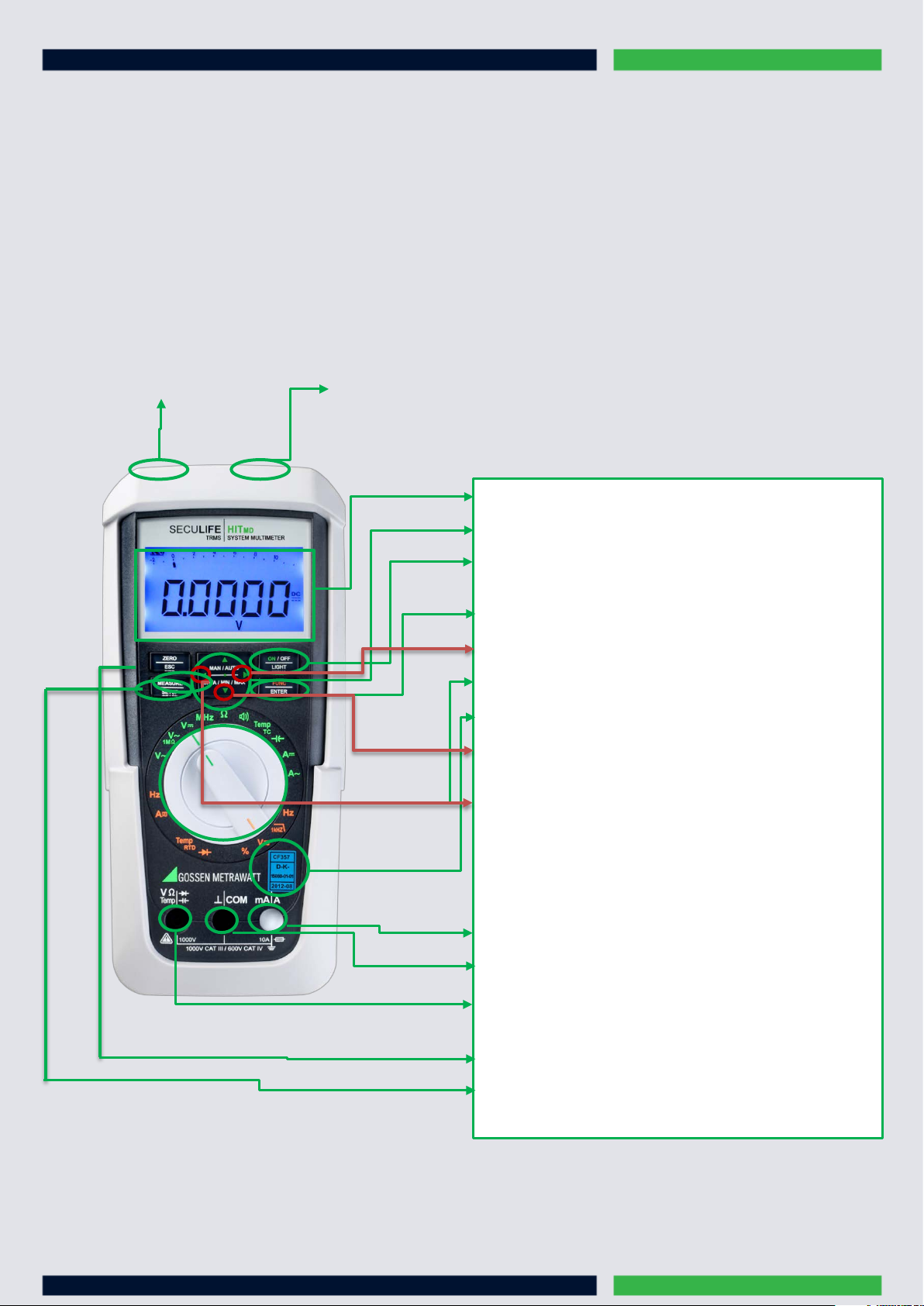
Display (LCD)
MAN / AUTO
ON / OFF | LIGHT:
FUNC | ENTER
Rotary switch
DATA / MIN / MAX
ZERO | ESC
MEASURE | SETUP
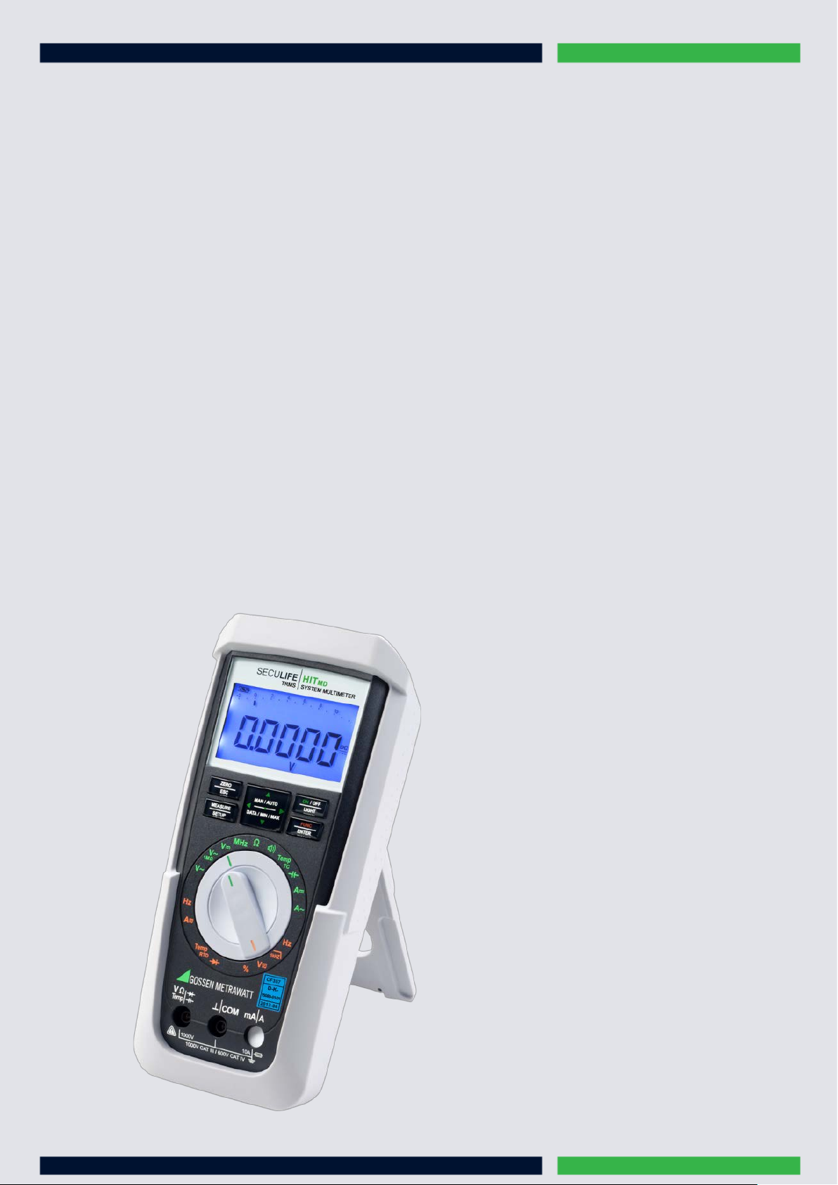
The measurement and testing of measuring equipment in the field of medical technology necessitates absolute reliability and a broad range of
applications. The SECU
the field of medical technology.
HITMD has been custom tailored to fulfill these demands: It’s the ideal device for testing, training and production in
The SECU
measuring even easier and more reliable. A broad range of functions that fulfill the requirements of demanding medical technology. And of
course world-class quality which is highly convincing all the way down to the finest details.
HITMD TRMS multimeter offers an entirely new dimension of measuring convenience: ultramodern ergonomics which make
Connector for power pack Infrared interface
: shift key for manual/automatic range selection
key for switching the device and the display illumination
on and off
: multifunction key
>Increase measuring range or move decimal point to the right (MAN function)
: for measuring functions
DAkkS calibration mark
: key for freezing, comparing and deleting measured
values and for min/max
<Decrease measuring range or move decimal point to the left (MAN function)
Connector socket for current measurement with automatic blocking
Connector socket for current measurement for ground
Connector socket for voltage, resistance, temperature, diode and capacitance
measurement
: key for zero balancing
: key for switching back and forth between measuring and
menu functions
1
Page 3
Housing and protective rubber holster with antimicrobial properties
• 23 multimeter functions
• Voltage measurement
• Auto-ranging current measurement from 100 A (resolution: 10 nA) to 1 A (16 A)
• Capacitance and resistance measurement, diode and continuity testing
• Measuring categories: 600V CAT III and 300V CAT IV
• 1 kHz low-pass filter
• TRMS AC and AC+DC, 20 kHz bandwidth
• Data storage for more than 15,000 measured values
•
Interfaces:
• Bidirectional infrared interface for communication with the PC (38.4 kBd)
• Optionally available IR-USB adapter
Power supply: battery or mains operation via optional broad range variable power pack (95 to 250 V AC)
• IP 52 protection against dust and water
• Automatic blocking sockets (ABS)
• Separate battery and fuse compartments
• Made in Germany
• Furnished with DAkkS calibration certificate
2
Page 4
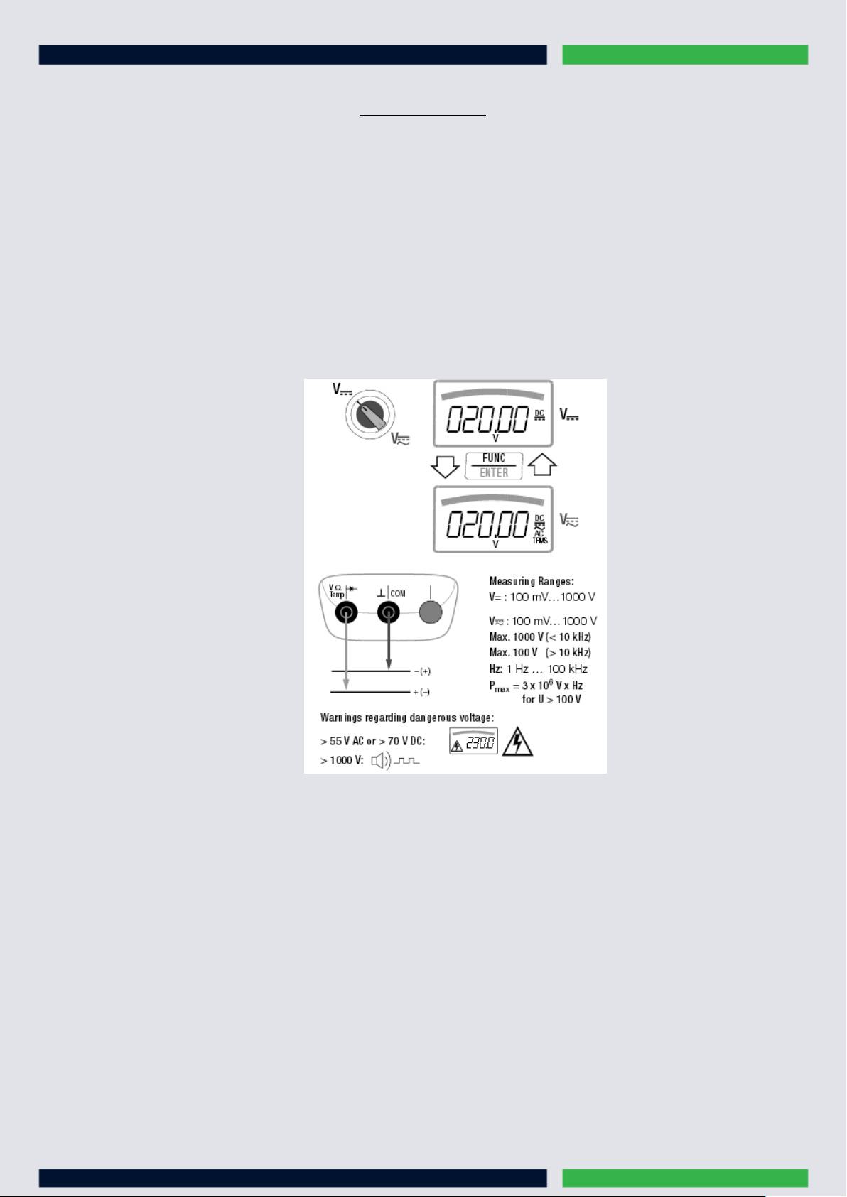
Voltage Measurement
MAN / AUTO
1. In accordance with the voltage to be measured, turn the rotary switch to V= or V~=
2. Connect the measurement cables as shown. The connector jack should be grounded.
Make sure that a current measuring range (“A”) has not been activated when the multimeter is connected for voltage
measurement! If the fuse’s blowing limits are exceeded as a result of operator error, both the operator and the
instrument are in danger! With the rotary switch in the V position, the multimeter is always set to the 1 V measuring
range immediately after it is switched on. As soon as the
value is less than 90 mV, the multimeter is switched to the mV measuring range.
key is pressed, and assuming the measured
Connection of the measurement cables
3
Page 5

Alternating Voltage Measurement with 1 MΩLoad Resistance and Frequency Measurement with Selectable
Voltage measurement:
FUNC | ENTER
Frequency Measurement:
FUNC | ENTER
Low-Pass Filter
1. In accordance with the voltage to be measured, turn the rotary switch to V~
2. Connect the measurement cables as shown. The „⊥“ should be gounded
1. You can switch back and forth between voltage measurement with and without low-pass filter
2.
Press the
1. Apply the measured quantity in the same way as for voltage measurement
2. Manually select the measuring range for the voltage amplitude. When the instrument is switched to frequency measurement, the
previously selected voltage measuring range remains active.
3. You can switch back and forth between frequency measurement with and without low-pass filter. Press the
multifunction key repeatedly until unit of measure Hz or Hz/Fil appears at the display
multifunction key repeatedly until the unit of measure V or. V/Fil appears at the display
1MΩ
or 1kHz
Connection of the measurement cables
4
Page 6

Alternating Voltage and Frequency Measurement V AC and Hz with Selectable Low-Pass Filter
FUNC | ENTER
FUNC | ENTER
1. In accordance with the voltage or frequency to be measured, turn the rotary switch to V~ or Hz.
2. Connect the measurement cables as shown. The “⊥” connector jack should be grounded
Voltage measurement:
1. You can switch back and forth between voltage measurement with and without low-pass filter
2. Press the
Frequency Measurement:
1. Apply the measured quantity is the same way as for voltage measurement
2. Manually select the measuring range for the voltage amplitude. When the instrument is switched to frequency measurement, the
previously selected voltage measuring range remains active
3. You can switch back and forth between frequency measurement with and without low-pass filter. Press the
multifunction key repeatedly until unit of measure Hz or Hz/Fil appears at the display.
multifunction key repeatedly until unit of measure V or V/Fil appears at the display
Connection of the measurement cables
5
Page 7

Resistance Measurement „Ω“
FUNC| ENTER
1. Disconnect supply power from the electrical circuit of the device to be measured, and discharge all high-voltage capacitors
2. Make sure that the device under test is voltage-free. Interference voltages distort measurement results!
3. Set the rotary switch to „Ω“.
4. Connect the DUT as shown
Continuity Test
1. Disconnect supply power from the electrical circuit of the device to be measured, and discharge all high-voltage capacitors
2. Make sure that the device under test is voltage-free. Interference voltages distort measurement results!
3. Set the rotary switch to the speaker sign (as shown as in the picture)
4. Connect the conductor path under test as shown
Diode Testing with a Constant Current of 1 mA
1. Disconnect supply power from the electrical circuit of the device to be measured, and discharge all high-voltage capacitors
2. Make sure that the device under test is voltage-free. Interference voltages distort measurement results!
3. Set the rotary switch to ->I
4. Press the
5. Connect the DUT as shown
key
6
Page 8

Temperature Measurement
Measurement with Thermocouples, Temp TC:
Measurement with Resistance Thermometers
ZERO | ESC
FUNC | ENTER
ZERO | ESC
FUNC | ENTER
1. Set the rotary switch to „Temp
2. The reference temperature is measured at the internal reference junction
3. Connect the sensor to the two accessible jacks. The instrument displays the measured temperature using the selected unit of
measure
”
TC
Set the rotary switch to „TempTC“ or „Temp
Automatic Compensation:
1. Press the
If you prefer to enter cable resistance directly, you can skip the following entry prompt
2. Short circuit the measuring instrument’s connector cables. “000.00” appears at the display. After pressing the
automatic compensation of cable resistance is activated for all subsequent measurements. The short-circuit can now be liminated,
and the device is ready for use
Entering
Cable Resistance:
1. Press the
2. Enter the known resistance of the connector cables with the scroll keys: Select the digit to be changes with the < > keys, and
change the respectively selected digit with the up, down keys. The default value is 0.43 Ω. Values can be selected within a range
of 0 to 50 Ω
3. Upon pressing the
resistance remains in memory even after the instrument has been switched off
key. „Short leads“ appears on the display
key once again in the automatic compensation menu
”
RTD
key, the selected value is activated and the display is returned to the measuring function. Cable
key,
7
Page 9

Capacity Measurement
1. Disconnect supply power from the electrical circuit of the device to be measured, and discharge all high-voltage capacitors
2. Make sure that the device under test is voltage-free. Capacitors must always be discharged before measurement is performed.
3. Set the rotary switch to „ “
4. Connect the (discharged!) device under test to the sockets with the measurement cables as shown
8
Page 10

Current Measurement
FUNC | ENTER
Notes Regarding Current Measurement:
• The multimeter may only be operated with installed batteries or rechargeable batteries. Dangerous currents are otherwise not indicated, and
the instrument may be damaged
• Set up the measuring circuit in a mechanically secure fashion, and secure it against inadvertent breaks. Select conductor cross-sections
and lay out connections such that they do not overheat
• An intermittent acoustic signal warns of current greater than 10 A. A continuous acoustic signal warns of current greater than 16 A
• The input for the current measuring range is equipped with a fuse link. Maximum permissible voltage for the measuring circuit (= rated
voltage of the fuse) is 1000 V AC/DC. Use specified fuses only! The fuse must have a breaking capacity of at least 30 kA
• If the fuse for the active current measuring range blows, “FUSE” appears at the digital display, and an acoustic signal is generated at the
same time
• If a fuse should blow, eliminate the cause of overload before placing the instrument back into service!
• Be absolutely certain that the measuring ranges are not overloaded beyond their allowable capacities.
Direct and Pulsating Current Measurement, Direct Connection, A DC and A (DC+AC) :
1. First disconnect supply power from the measuring circuit or the power consumer (1), and discharge any capacitors
2. In accordance with the current to be measured, turn the rotary switch to A= or A~=
3. Select the current type appropriate for the measured quantity by briefly pressing the
Each time the key is pressed, the instrument is switched back and forth between A DC and A (DC + AC) TRMS, which is
indicated by means of an acoustic signal. The current type is indicated at the LCD by means of the DC or the
(DC+AC)TRMS symbol
4. Safely connect the measuring instrument (without contact resistance) in series to the power consumer (2) as shown
5. Switch supply power to the measuring circuit back on (3)
6. Read the display. Make a note of the measured value if the instrument is not being operated in the memory mode or the
transmission mode
7. Disconnect supply power from the measuring circuit or the power consumer (1) once again, and discharge any
capacitors
8. Remove the test probes from the measuring point and return the measuring circuit to its normal condition
multifunction key.
9
Page 11

Alternating Current and Frequency Measurement, Direct Connection, A AC and Hz
FUNC | ENTER
1. First disconnect supply power from the measuring circuit or the power consumer (1), and discharge any capacitors.
2. In accordance with the current or frequency to be measured, turn the rotary switch to A~ or Hz
3. Select the desired measured quantity by briefly pressing the
pressed, AC
4. Safely connect the measuring instrument (without contact resistance) in series to the power consumer as shown.
5. Switch supply power to the measuring circuit back on (3)
6. Read the display. Make a note of the measured value if the instrument is not being operated in the memory mode or the
transmission mode
7. Disconnect supply power from the measuring circuit or the power consumer (1) once again, and discharge any
capacitors
8. Remove the test probes from the measuring point and return the measuring circuit to its normal condition
and Hz are alternately selected, and switching is acknowledged with an acoustic signal.
TRMS
multifunction key. Each time the key is
10
Page 12

GMC-I Messtechnik GmbH
Südwestpark 15 □ 90449 Nürnberg □ Germany
TEL +49 911 8602-111 □ FAX +49 911 8602-777
www.gossenmetrwawatt.com □ info@gossenmetrwawatt.com
 Loading...