

Page 1
Operating Instructions
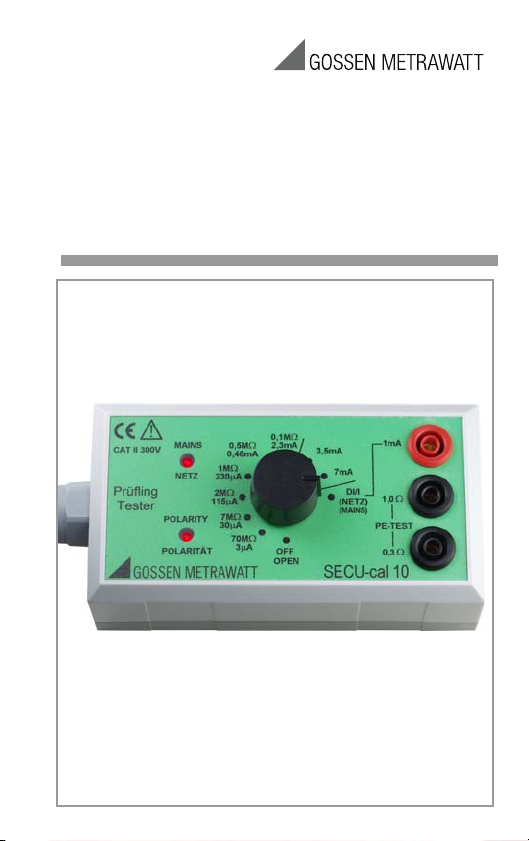
SECU-cal 10
Calibration Adapter for Testers
per DIN VDE 0701-0702/
EN 62353 (VDE 751-1)
3-349-169-15
7/2.13
Page 2
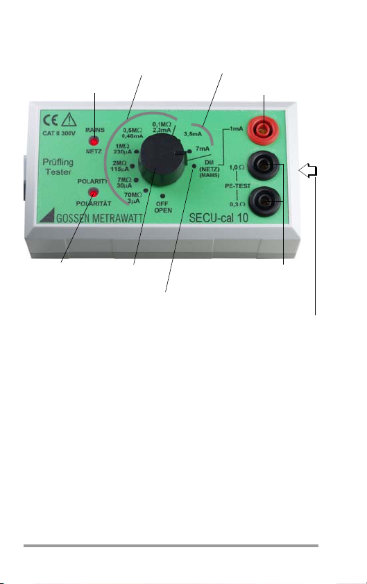
Function selector
1mA terminal
Reference terminals
Mains indicator lamp
Polarity display
for test instrument probe
for measurement of R
PE
may not light up
Reference values for equivalent
leakage current measurement I
EA
during
Tests with line voltage!
– Leakage current measurement
– Residual current measurement
with the help of an ammeter, see
chapter 5 regarding connection
with max. 1 A test current
measurement!
Lateral imprint
showing the reference values
of test resistances R
PE
switch
Reference values for
measurement of R
ISO
and equivalent leakage current I
EA
Note
The indicated current values of 30 mA and 3 mA for switch
positions 7 M and 70 M are merely guidance values.
Usually, the capacitance of the connector cables is sufficiniently high to ensure that the current values actually measured exceed considerably that level and can therefore not be
used as reference values.
This applies particularly for the test instruments of the SECUTEST
2 GMC-I Messtechnik GmbH
®
... series.
Page 3

Contents Page
1 Applications ..................................................................4
2 Safety Features and Precautions ..................................4
3 Connecting the Calibration Adapter to the Test
Instrument ....................................................................7
3.1 Tests without Line Voltage .......................................................... 7
3.2 Tests with Line Voltage ..............................................................7
4 Performing Tests without Line Voltage .........................8
4.1 Checking Display Values for Protective Conductor Resistance
Measurement ............................................................................ 8
4.2 Checking Display Values for Insulation Resistance Measurement ..8
4.3 Checking Display Values for Equivalent Leakage Current
Measurement ............................................................................ 9
4.4 Checking Display Values for Equivalent Device Leakage Current
Measurement per DIN EN 62353 (VDE 0751-1) ......................... 10
4.5 Checking Display Values for Equivalent Patient Leakage
Current Measurement per DIN EN 62353 (VDE 0751-1) ............. 10
5 Performing Tests with Line Voltage ............................11
5.1 Checking Display Values for Leakage Current Measurement ....... 11
5.2 Checking Display Values for Patient Leakage Current
Measurement .......................................................................... 12
6 Characteristic Values .................................................. 13
6.1 Nominal Range of Use .............................................................. 13
6.2 Ambient Conditions .................................................................. 13
6.3 Electrical Safety ....................................................................... 13
6.4 Mechanical Design ................................................................... 13
7 Maintenance ...............................................................14
7.1 Housing Maintenance ............................................................... 14
7.2 Device Return and Environmentally Compatible Disposal ............14
8 Repair and Replacement Parts Service
Calibration Center and Rental Instrument Service .....15
9 Product Support ..........................................................15
GMC-I Messtechnik GmbH 3
Page 4

1 Applications
Attention!
!
The adapter is used for testing measuring accuracy of test
instruments in accordance with DIN VDE 0701-0702 and
DIN EN 62353 (VDE 0751-1). As a rule, these instruments
must be tested once each year as set forth by accident prevention regulation BGV A3 (formerly BGV A2 and/or VBG4), as
well as for certification in accordance with the ISO 9000 quality standard.
All measuring ranges for tests required in accordance with
DIN VDE 0701-0702 such as protective conductor resistance,
insulation resistance, equivalent leakage current and residual
and/or contact current must be tested.
2 Safety Features and Precautions
This instrument fulfills the requirements of the applicable European and national EC guidelines. We confirm this with the CE
marking. The relevant declaration of conformity can be
obtained from GMC-I Messtechnik GmbH.
The SECU-cal 10 calibration adapter is manufactured and
tested in accordance with safety regulations IEC 61010-1 /
EN 61010-1 / VDE 0411-1.
If used for its intended purpose, safety of the user and of the
device is assured.
Read the operating instructions completely and carefully
before using the adapter, and follow all instructions included
therein. Observe the operating instructions included with the
test instrument to be tested as well.
The calibration adapter may only be used for testing
test instruments in accordance with DIN VDE 0404!
Under no circumstances may the adapter be used
in electrical systems!
4 GMC-I Messtechnik GmbH
Page 5
Attention!
Before plugging the calibration adapter into a live
Attention!
Attention!
!!!
outlet (test socket or mains outlet) for the performance of tests with line voltage, set the rotary
switch at the calibration adapter to the DI/I position.
Non-observance may result in:
• Destruction of the adapter
• Charging of the protective conductor with impermissible
fault currents of up to 8.25 mA
• Tripping of 10 mA RCCBs
If the “NETZ/MAINS” and “POLARITÄT/POLARITY” lamps light
up simultaneously during the test with mains voltage in rotary
switch position DI/I, the polarity of the calibration adapter must
be reversed before measurement is performed. Only the
“NETZ/MAINS” lamp may remain illuminated. Non-observance may result in erroneous measurements.
Only test instruments with a protective conductor test
current of no greater than 1 A may be connected to the
calibration adapter. Greater current values result in
destruction of the adapter.
The device is not equipped with overcurrent or
excessive temperature protection.
Under no circumstances may the device’s load
capacities be exceeded, because this may damage
the device or reduce its level of accuracy.
GMC-I Messtechnik GmbH 5
Page 6
Visual Inspection of Test Instruments
!
Perform a visual inspection of test instruments and their connector cables before connecting them to the calibration
adapter. Damaged test instruments must first be repaired.
The calibration adapter may not be used:
• with open housing
• if visible damage is apparent
• if the connection cable is damaged
• if it no longer functions flawlessly
• if the safety sockets are damaged
• after excessive stress, i.e. if the load capacities specified
in the technical data have been exceeded
• after lengthy periods of storage under unfavorable conditions (e.g. humidity, dust, temperature)
The calibration adapter may only be repaired by the manufacturer. Observance of technical measuring and safety requirements cannot otherwise be assured.
Meanings of symbols on the device
The symbols on the device have the following meanings:
Indicates EC conformity
Warning concerning a source of danger
(Attention, observe documentation!)
This device may not be disposed of with the trash.
Further information regarding the WEEE mark can be
accessed on the Internet at
www.gossenmetrawatt.com by entering the search
term ’WEEE’.
6 GMC-I Messtechnik GmbH
Page 7

3 Connecting the Calibration Adapter to the Test
Instrument
3.1 Tests without Line Voltage
➭ Make sure that the test socket is voltage-free
(e.g. set Mains VDE (Netz-VDE) switch to VDE position for
SECUTEST
➭ The earthing contact outlet of the calibration adapter may
only be plugged into the earthing contact outlet of the test
instrument, identified as test socket.
Reversal of L and N at the outlet has no effect on measurement results.
3.2 Tests with Line Voltage
➭ Before connecting the calibration adapter to the test
socket: Set the rotary switch to the DI/I position.
The rotary switch must also be set to the DI/I position for auto-
matic test instruments, and for test panels with VDE MAINS
selector switches before activating the test function (i.e. before
starting the function test).
If the “NETZ/MAINS” and “POLARITÄT/POLARITY” lamps light
up simultaneously, mains plug polarity must be reversed for
the test instrument or the calibration adapter before measurement is performed.
Only the “NETZ/MAINS” lamp may be illuminated during measurement.
®
11P, 15P or 21F workshop test panels).
GMC-I Messtechnik GmbH 7
Page 8
4 Performing Tests without Line Voltage
Attention!
!
➭ Connect the test instrument to mains power.
➭ Make sure that the test socket at the test instrument is
voltage-free.
➭ Plug the earthing contact plug of the calibration adapter
into the test socket at the test instrument.
4.1 Checking Display Values for Protective Conductor Resistance Measurement
Use test instruments with test current of less than
1 A only. The reference resistors are destroyed at
values of greater than 1 A.
➭ Connect the probe from the test instrument to the “0.3 ”
or “1.0 ”socket at the calibration adapter.
➭ Start “protective conductor measurement” at the test in-
strument.
The value displayed at the test instrument must lie within the
test instrument’s specified operating error tolerance for the
selected test type, plus calibration adapter error.
The reference values of the test resistances R
on the front side of the calibration adapter and in the test
report. Please use these values for assessing your DUT.
Calibration adapter intrinsic error for protective conductor
resistance measurement: 1%
4.2 Checking Display Values for Insulation Resistance Measurement
➭ Start “insulation measurement” at the test instrument.
➭ Set the selector switch at the calibration adapter to either
70 or 0.1 M.
The value displayed at the test instrument must lie within the
test instrument’s specified operating error tolerance for the
selected test type, plus calibration adapter error.
Calibration adapter intrinsic error for various insulation resistance values
Value in M 70 0.1 7
Intrinsic error as % 10.5
are indicated
PE
8 GMC-I Messtechnik GmbH
Page 9

4.3 Checking Display Values for Equivalent Leakage Current Mea-
Note
surement
➭ Start “equivalent leakage current measurement” at the
test instrument.
➭ Set the selector switch at the calibration adapter to either
3.5 or 7 mA.
The value displayed at the test instrument must lie within the
test instrument’s specified operating error tolerance for the
selected test type, plus calibration adapter error.
I
[mA] = 230 V
Display
Rxrepresents the resistors integrated into the SECU-cal 10. Any possi-
ble phase error is avoided through the use of ohmic resistors.
represents the internal resistance of the test instrument during equiv-
R
i
alent leakage current measurement. It amounts to typ. 2 k, according to standard.
Rx + R
i
Calibration adapter intrinsic error for equivalent leakage current measurement: 1 %
Before introduction of the DIN VDE 0701:2000-09
standard, the display value was calculated according
to the following formula:
I
[mA] = 230 x 1.06
Display
Rx + 2 k,
i.e. the display value included an allowance of 6%.
Veteran instruments therefore show an equivalent
leakage current increased by 6 %. We recommend
upgrading such instruments to the current version as
soon as possible.
GMC-I Messtechnik GmbH 9
Page 10

4.4 Checking Display Values for Equivalent Device Leakage Current Measurement per DIN EN 62353 (VDE 0751-1)
➭ Start “equivalent leakage current measurement
(Ri = 1 k)” at the test instrument.
➭ Connect the probe to the 0.3 socket.
In accordance with DIN EN 62353 (VDE 0751-1), the protective conductor at the test socket is not connected. The
probe functions as a return conductor.
The value displayed at the test instrument must lie within the
test instrument’s specified operating error tolerance for the
selected test type, plus calibration adapter error.
I
[mA] = 230 V
Display
Rxrepresents the resistors integrated into the SECU-cal 10. Any possi-
ble phase error is avoided through the use of ohmic resistors.
R
represents the internal resistance of the test instrument during equiv-
i
alent device leakage current measurement. It amounts to typ. 1 k,
according to standard.
Rx + R
i
Nominal Values
Switch Positions
70 M 3.29 A 3.29 A
7 M 32.8 A 32.8 A
2 M 115 A 115 A
1 M 0.23 mA 0.23 mA
0.5 M 0.46 mA 0.46 mA
0.1 M 2.25 mA 2.28 mA
3.5 mA 3.5 mA 3.55 mA
7 mA 7.0 mA 7.22 mA
Equivalent Leakage
Current
Equivalent Device
Leakage Current
4.5 Checking Display Values for Equivalent Patient Leakage Current Measurement per DIN EN 62353 (VDE 0751-1)
Plug the calibration adapter into the test socket at the test
instrument. Plug the probe into sockets 4 and 5 at the test
instrument. The probe handle is left open and may not be
touched (hum). Connect one of the applied parts sockets (A
through K) to the 1 mA socket at the SECU-cal 10. The
included quick clip and a 2 mm cable can be used to this end.
Start “equivalent patient leakage current measurement” at the
10 GMC-I Messtechnik GmbH
Page 11
test instrument. The display value must lie within a range of
Attention!
Note
!
0.98 mA and 1.01 mA plus the measuring uncertainty of the
test instrument. Other values cannot be tested with the SECUcal 10. In order to test all of the sockets (A through K) for correct functioning, connect each of these sockets with the 1 mA
socket at the SECU-cal 10, one after the other. The display
value must lie within the above specified range for each of the
sockets.
5 Performing Tests with Line Voltage
Set the rotary switch at the calibration adapter to
the DI/I position before plugging the calibration
adapter into the test socket.
The following test with line voltage must be performed with an
additional ammeter (calibrated multimeter, 1 mA respectively
10 mA AC range, e.g. METRAHIT X-TRA).
5.1 Checking Display Values for Leakage Current Measurement
The “POLARITÄT/POLARITY” lamp may not light up
during measurement.
➭ Start the requested leakage current measurement with
mains voltage at the test instrument.
➭ Connect the “contact and probe current measurement”
socket at the test instrument to the “1 mA” safety socket
at the calibration adapter via a series connected multime-
ter with the help of measurement cables.
The values displayed at the multimeter and the test instrument
must be in compliance by taking device tolerances into
account.
Line voltage tolerances influence measurement results.
GMC-I Messtechnik GmbH 11
Page 12

5.2 Checking Display Values for Patient Leakage Current Measurement
This test can be performed with all test instruments of the
SECUTEST/SECULIFE series with sockets A through K for
applied parts.
Please proceed as follows to calibrate the patient leakage current with SECU-cal 10:
➭ Connect SECU-cal 10 with the test socket.
➭ Select function „I-leakage“ at the SECUTEST (via switch po-
sition or menu), and then patient leakage current.
➭ Start measurement.
➭ Connect the applied part A to the 0.3 Ohm socket of
SECU-cal 10 via a series connected multimeter with the
help of measurement cables.
➭ Select „SFC Prot. Cond. interrupted“.
➭ Set the requested leakage current at the SECU-cal 10 test
instrument (e. g. 115 μA).
The values displayed at the multimeter and the test instrument
must be in compliance by taking device tolerances into
account.
12 GMC-I Messtechnik GmbH
Page 13

6 Characteristic Values
6.1 Nominal Range of Use
Maximum Voltage For the measurement of
Maximum Current For the measurement of protective
AC frequency: 50 Hz 60 Hz, sinusoidal
6.2 Ambient Conditions
Operating Temperature 0 C +40 C
Storage Temperature –20 C +60C
6.3 Electrical Safety
Safety Class I per IEC 61010-1
Operating Voltage 300 V
Measuring Category I for insulation resistance
Pollution degree 2
EMC IEC/EN 61326
6.4 Mechanical Design
Protection housing: IP 40, terminals: IP 20
Extract from table on the meaning of IP codes
IP XY
(1
Protection against
st
digit X)
foreign object entry
0 not protected 0 not protected
2 12.5 mm dia. 2
4 1.0 mm dia. 4 splashing water
Dimensions
Weight approx. 0.26 kg
Insulation resistance: 600 V DC
Equivalent leakage/equivalent
device leakage current: 250 V AC
Equivalent patient leakage current:
250 V AC
Leakage current: 250 V AC
conductor resistance:
1ADC/AC
Insulation resistance: 2 mA
Equivalent leakage current:
3.5 mA AC
II for all other measurements
IP XY
(2nd digit Y)
Protection against the
penetration of water
vertically falling drops
with enclosure tilted 15
125 mm x 66 mm x 41 mm (L x W x H)
eff
eff
GMC-I Messtechnik GmbH 13
Page 14

7 Maintenance
Annual calibration, performed by the manufacturer, is recommended.
7.1 Housing Maintenance
No special maintenance is required for the housing. Keep outside surfaces clean. Use a slightly dampened cloth for cleaning. Avoid the use of solvents, cleansers and abrasives.
7.2 Device Return and Environmentally Compatible Disposal
The instrument is a category 9 product (monitoring and control
instrument) in accordance with ElektroG (German Electrical
and Electronic Device Law). This device is not subject to the
RoHS directive.
We identify our electrical and electronic devices (as of
August 2005) in accordance with WEEE 2002/96/EG
and ElektroG with the symbol shown to the right per
DIN EN 50419.
These devices may not be disposed of with the trash. Please
contact our service department regarding the return of old
devices.
14 GMC-I Messtechnik GmbH
Page 15

8 Repair and Replacement Parts Service
Calibration Center* and Rental Instrument Service
When you need service, please contact:
GMC-I Service GmbH
Service Center
Thomas-Mann-Strasse 20
90471 Nürnberg • Germany
Phone +49 911 817718-0
Fax +49 911 817718-253
E-mail service@gossenmetrawatt.com
www.gmci-service.com
This address is only valid in Germany.
Please contact our representatives or subsidiaries for service
in other countries.
* DAkkS Calibration Laboratory
for Electrical Quantities D-K-15080-01-01
accredited per DIN EN ISO/IEC 17025:2005
Accredited measured quantities: direct voltage, direct current values,
DC resistance, alternating voltage, alternating current values, AC
active power, AC apparent power, DC power, capacitance, frequency
and temperature
9 Product Support
When you need support, please contact:
GMC-I Messtechnik GmbH
Product Support Hotline
Phone +49 911 8602-0
Fax +49 911 8602-709
E-Mail support@gossenmetrawatt.com
GMC-I Messtechnik GmbH 15
Page 16

Edited in Germany • Subject to change without notice • A pdf version is available on the internet
GMC-I Messtechnik GmbH
Südwestpark 15
90449 Nürnberg •
Germany
Phone +49 911 8602-111
Fax +49 911 8602-777
E-Mail
info@gossenmetrawatt.com
www.gossenmetrawatt.com
 Loading...