

Page 1

Interface description
R2601
DIN Draft 19244 Interface
3-348-815-15
7/6.10
Page 2

Page 3

GMC-I Messtechnik GmbH 3
INHALT Seite INHALT Seite
1 General ..................................................................................... 4
1.1 Interface hardware ..................................................................... 4
1.2 Communications protocol ........................................................... 4
1.3 How to connect the interface ...................................................... 5
1.4 Principal function ....................................................................... 6
1.5 Time action................................................................................ 7
2 Telegram structure..................................................................... 8
2.1 Short set.................................................................................... 8
2.2 Control set................................................................................. 9
2.3 Long set.................................................................................. 10
2.4 Function and value range of the format characters ..................... 11
2.5 Criteria for the validity of a request telegram.............................. 14
3 Telegram contents R2601 ........................................................ 15
3.1 Equipment reset....................................................................... 15
3.2 Interrogation: Equipment OK? ................................................... 15
3.3 Request for cycle data.............................................................. 16
3.4 Request for event data ............................................................. 17
3.5 Request data from R2601 ........................................................ 20
3.6 Send data to R2601................................................................. 22
4 Parameter indices of the equipment parameters ........................ 24
4.1 Temperature parameters .......................................................... 24
4.2 Control parameters.................................................................. 28
4.3 Control instructions.................................................................. 29
4.4 Equipment specifications ......................................................... 32
4.5 Heating current monitor ........................................................... 37
5 Storage operations .................................................................. 38
5.1 Request a record..................................................................... 38
5.2 Send a record ......................................................................... 39
Page 4
GMC-I Messtechnik GmbH 4
1 General
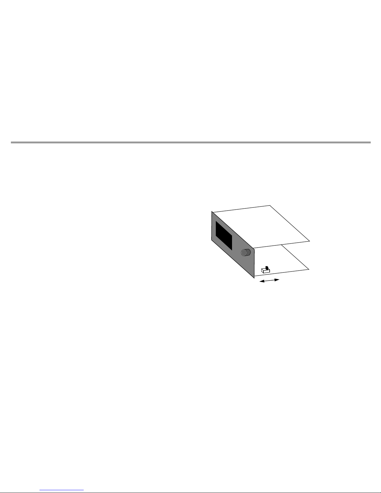
1.1 Interface hardware
To communicate with a host computer, an SPS, etc., the controller R2601 must be equipped with marking F1. In this case, the controllers are equipped
with a serial interface having the following data:
Level types RS-232 and RS-485 (two-wire)
in the unit selectable
Baud rate 9600 bd
Character format 8 data bits, 1 parity bit, 1 stop bit
Parity Even
Maximum number of equipment on the bus: 32
With RS-485 bus operation, each connected R2601 must
have a different interface address (Addr = 0 ... 250)
(see operating instructions 3-348-778-15).
1.2 Communications protocol
The transmission protocol used complies with DIN draft 19244. The R2601 uses only a partial amount of the defined functions which are described
below.
R
S
-
2
3
2
R
S
-
4
8
5
Page 5
GMC-I Messtechnik GmbH 5
1.3 How to connect the interface
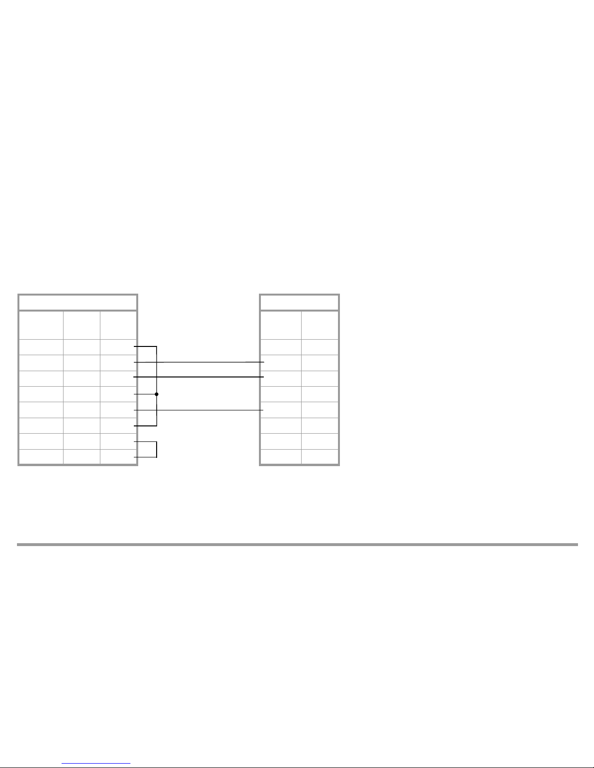
1.3.1 RS-232 connection
When using the a RS-232 interface, only one R2601 can be connected to a master (e.g. PC), for example, for pre-loading the unit with user-specific
data.
Depending upon the driver software, the jumpers on the master side can be omitted and/or can be different.
Sub-D socket R2601
Number
of pins:
25 9
DCD 8 1
RxD 3 2 20 TxD
TxD 2 3 21 RxD
DTR 20 4
Gnd 7 5 19 Gnd
DSR 6 6
RTS 4 7
CTS 5 8
Page 6

GMC-I Messtechnik GmbH 6
1.3.2 RS-485 connection
When using a RS-485 interface, as many as 32 equipment (R2601 and others) can be connected to the bus.
Thereby, all terminals A, B and/or C are interconnected in parallel. The wiring must be made from equipment to equipment and must not be a star connection. With longer bus lines (longer than about 5 m) the bus should be terminated at both ends with the characteristic impedance
(e.g. 200 between A and B).
When using the 1799-V5040 interface converter on the master, the following pins are connected on the Sub-D plug:
A = 3 B = 8 C = 5
1.4 Principal function
Involved is a master/slave protocol with a fixedly assigned master (e.g. SPS) and as many as 255 slaves (equipment e.g. R2601).
Communication is in half-duplex mode.
An equipment connected to the master becomes active (responds) only, when
– it receives a valid telegram addressed to itself and
– the minimum specified response delay time (t
av) has elapsed so that the host computer has time to get ready to receive data.
Master R2601 R2601
A21 21
B20 20
C19 19
Page 7
GMC-I Messtechnik GmbH 7
Following, the master may only become active again, when
– it receives a reply telegram from the addressed equipment and the specified wait time after a reply telegram (t aw) has elapsed, or
– the maximum specified response delay time (t
av) has elapsed.
Within a telegram, pauses of limited duration (t zv = character delay time) may occur between 2 character transmissions.
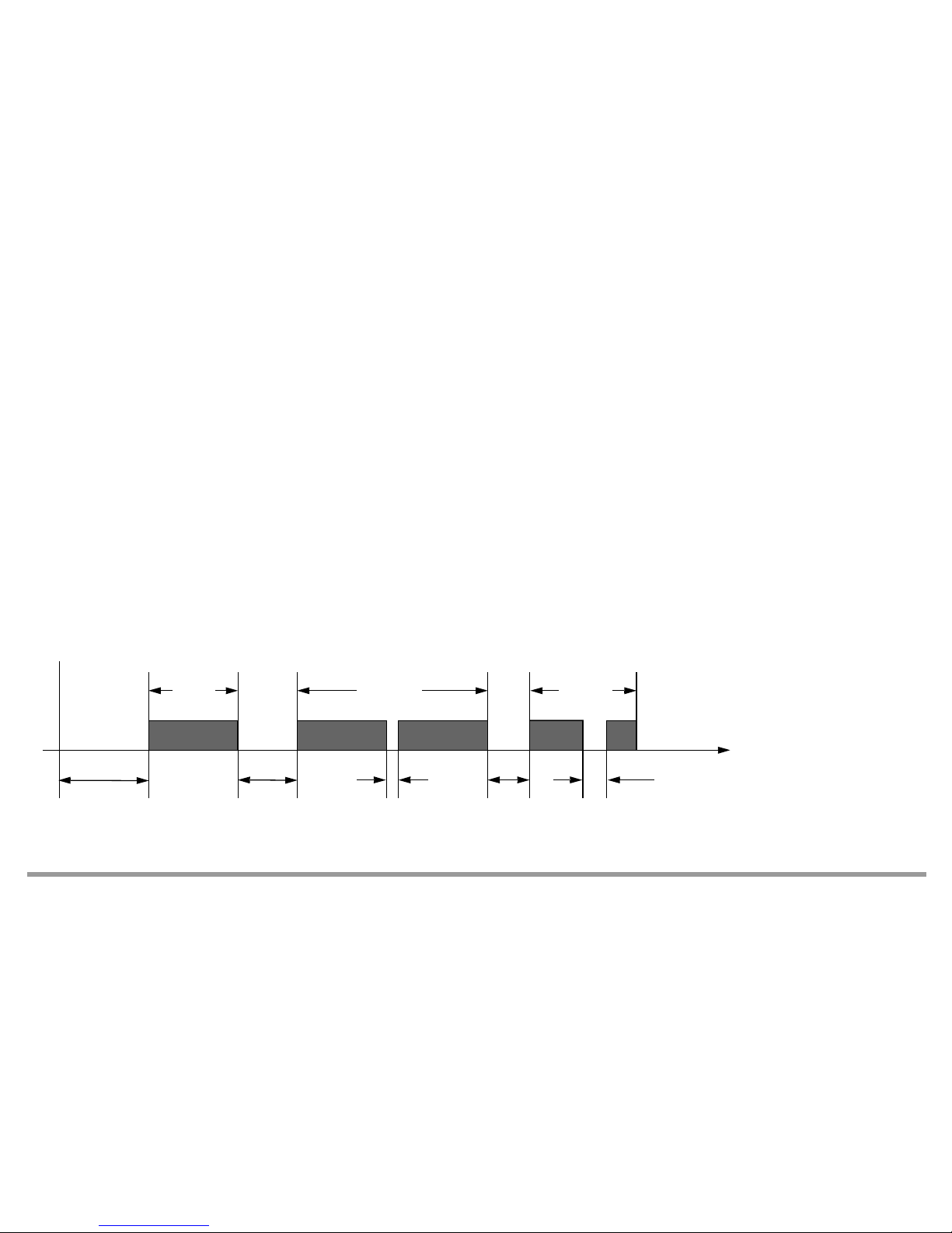
1.5 Time action
Ready to send/receive after turn-on t ber approx. 5 s
Character delay time (R2601 transmitter) t
zvs <3ms
Character delay time (master) t
zvm < 500 ms
Response delay time (R2601 transmitter) 10 ms < t
av <100 ms
Wait time after R2601 response (master) t
aw > 10 ms
Time
Master
sends
Equipment
responds
t
ber
approx. 5 s
t
av
10 ...
100 ms
tzvs
< 3 ms
Master
sends
taw
> 10 ms
t
zvm
< 500 ms
Page 8

GMC-I Messtechnik GmbH 8
2 Telegram structure
All telegrams consist of one of 3 sets in both request and reply direction, they differ in their principal structure.
Their use is fixed for each interface function of the R2601.
Structure and use of the set types are described as follows.
2.1 Short set
Short sets are used on the request side (from the master)
for transmission of short instructions to the equipment (e.g. Reset)
for short requests of important data from the equipment (e.g. event data)
Short sets are used on the reply side (from the R2601)
for acknowledgement of requests that require no reply data.
Principal construction short set
Character No. Contents Meaning Remarks
1 10h Start character Especially for short set
2 0 ... FAh, FFh Equipment address Addr and/or 255 (see 2.4.1)
3 Function field (FF) see 2.4.2
4 Checksum (PS) = Equipment address + FFh
5 16h End character Common to all set types
Page 9

GMC-I Messtechnik GmbH 9
2.2 Control set
The R2601 uses control sets on the request side only. They serve to request all equipment data that cannot be requested via a short set because a
detailed specification is required for them.
Principal construction control set
Character No. Contents Meaning Remarks
1 68h Start character
2 3 and/or 6 Length Number of characters from equipment address to checksum exclusive
3 3 and/or 6 Length (repeat)
4 68h Start character (repeat)
5 0 ... FAh, FFh Equipment address Addr and/or 255 (see 2.4.1)
6 Function field (FF) see 2.4.2
7 Parameter index (PI) see 2.4.3
8 1 From channel For reasons of compatibility with multi-channel controllers these charac-
ters must be available, omitted for parameter index 30h ... 3Fh.
9 1 To channel
10 0 Receipt number
8 and/or 11
Checksum (PS)
1)
1) For the set types, the checksum is formed by bytewise summation without overflow summation over all characters from the equipment address to checksum exclusive.
9 and/or 12 16h End character
Page 10

GMC-I Messtechnik GmbH 10
2.3 Long set
The R2601 uses long sets to transmit instructions and parameters to the equipment and to receive data from the equipment.
Principal construction long set
Character No. Contents Meaning Remark
1 68h Start character
2 Length Number of characters from equipment address to checksum
exclusive
3 Length (repeat)
4 68h Start character (repeat)
5 0 ... FAh, FFh Equipment address Addr and/or 255 (see 2.4.1)
6 Function field (FF) see 2.4.2.
7
Parameter index (PI)
1)
1) Omitted for reply cycle data and event data.
see 2.4.3.
81
From channel
1)
9
1
To channel
1)
Omitted for parameter index 30h ... 3Fh
10
0
Receipt number
1)
. . . n character data block see 2.4.4.
Length + 5
Checksum (PS)
2)
2) For the set types, the checksum is formed by bytewise summation without overflow summation over all characters from the equipment address to checksum exclusive.
Length + 6 16h End character
Page 11

GMC-I Messtechnik GmbH 11
2.4 Function and value range of the format characters
2.4.1 Equipment address
0 ... 250 Range for individual equipment addresses = interface address Addr
255 All equipment connected to a bus can simultaneously be addressed under this address. Data and instructions entered with this address
are accepted by all equipment, but there is no acknowledgement made to the master.
2.4.2 Function field (FF)
The function field contains
with the short set the proper user information, predefined by bits and different in request and response direction
with the control and long set the direction and control information for the transmitted data block
2.4.2.1 Function coding of the function field in request direction
Request check Code Set Remark
Reset equipment 09h
Interrogation: Equipment OK? 29h Short set
Request cycle data from equipment 89h The R2601 evaluates the given codes only; an error acknowledgement is issued
for invalid ones
Request event data from equipment A9h
Send data to R2601 69h Long set
Request data from R2601 89h
Page 12

GMC-I Messtechnik GmbH 12
2.4.2.2 Function coding of the function field (FF) in response direction
Bit No. Function Value Meaning
0 ... 2 Reserved 0, 0, 0 (fixed)
3 Request disable 01Instruction executed, equipment ready
Equipment not ready for this instruction, eventually repeat instruction
4 Instruction acknowledgement 01Instruction executed, equipment ready
Instruction could not be executed, equipment ready
5Transmission error 01Request telegram correct
Request telegram incorrect
6 Not used 0
7Service request 01None of the errors contained in error status words 1 and 2 occurred
One or more errors occurred, request error status for exact identification!
Page 13

GMC-I Messtechnik GmbH 13
2.4.3 Parameter index (PI)
The type of the data to be transmitted is defined via the parameter index. The "PI" character is interpreted as follows:
Functionally used data and/or setting parameters of an equipment are combined in the main parameter groups. Only those parameter indices documented in section 4 can be addressed in the R2601, an error message is issued for all others.
2.4.4 Length and format of the data block
Length and format of the data block are variable and a function of PI and FF.
The transmitted values can have byte or word format:
Bit 7-4 Bit 3-0
0 ... Fh 0 ... Fh
Selection number for main parameter group Selection number for a special parameter in the main group
8 Bit
Number without sign
Bit 2's complement presentation
Number with sign
16 Bit LS byte first
Number without sign
15 Bit LS byte first, 2's complement presentation
Number with sign
8/16 Bit LS byte first
Bit field
Page 14

GMC-I Messtechnik GmbH 14
2.5 Criteria for the validity of a request telegram
The R2601 checks the characters of the telegrams received in accordance with the following tables:
If incorrect values are received for FF, PI and PS, the R2601 responds with a short set with set transmission error bit. If the user data is entered beyond
its specific value ranges, the R2601 responds with a short set with set service request bit. The bit "impermissible value" is set in the error status word
2.
If there are other deviations or a parity error, the telegram is invalid, the R2601 does not respond.
For short set: For control and long set:
Character No. Criterion Character No. Criterion
1 10h 1 68h
2 Interface address Addr or 255 (see 2.4.2) 2 Note length for PS and end character
3 FF = valid function coding 3 Character 3 = character 2
4 PS = Addr or 255 + FF 4 68h
5 16h 5 Interface address Addr or 255
6 FF = 69h oder 89h
7 PI = valid parameter index (see section 4)
. . . (data block)
Length + 5
PS =
1)
1) Bytewise sum without overflow over all characters from equipment address (Addr or 255) to checksum exclusive
Length + 6 16h
Page 15

GMC-I Messtechnik GmbH 15
3 Telegram contents R2601
3.1 Equipment reset
The addressed equipment performs a hardware reset same as in the case of a short interruption of the auxiliary voltage.
Example: Equipment address = 2
3.2 Interrogation: Equipment OK?
The addressed equipment shows the function field only:
Example: Equipment address = 3
See 2.4.2.2 for contents of the function field.
Request from master (short set): 10h 02h 09h 0Bh 16h
FF PS
R2601 response: None
Request from master (short set): 10h 03h 29h 2Ch 16h
FF PS
R2601 response (short set): 10h 03h „FF“ „FF“+3 16h
Page 16

GMC-I Messtechnik GmbH 16
3.3 Request for cycle data
You will get the most important measuring and output values of the controller in one data package.
Cyclic requests of these values are thus made possible in compact form (short set request.
Example: Equipment address = 2
See 2.4.2.2 for contents of the function field (FF)
The 7 characters of the cycle data block have the following format:
Request from master (short set): 10h 02h 89h 8Bh 16h
FF PS
R2601 response (long set, see 2.3): 68h 09h 09h 68h 02h „FF“ Data block „PS“ 16h
Character No. Contents, e.g. Format Unit of measure Remark Condition
7, 8
2Ch, 01h 15 bits 1 / 0.1 / 1
1st measured value (e.g. 300)
9, 10 36h, 01h 15 bits 1 / 0.1 / 1 2nd measured value (e.g. 310) B3, B4, B5
0, 0 B1, B2
11
CEh 7 bits 1%
Actual ON time (e.g. –50 %)
12, 13 28h, 00h 15 bits 0.1 A Meas. val. of the heating curr. (e.g. 4,0 A)
A1, A2, A3
1% Position readback (e.g. 40 %)
A4
7 characters
Page 17

GMC-I Messtechnik GmbH 17
3.4 Request for event data
The event date, combined in 2 words, contain all error messages and alarms of the equipment.
They can be called up via short set to identify a special error.
This request can be made asynchronous, for example, if the service request bit (collected errors) was set before in any random response telegram in
the function field (FF).
Example: Equipment address = 5
See 2.4.2.2 for contents of the function field (FF)
The 4 characters of the event data block are bit fields which are combined to form the error status words 1 and 2.
These 4 characters can also be read by data request with parameter index 21h.
See the operating instructions for more explanations and information on error elimination.
Request from master (short set): 10h 05h A9h AEh 16h
R2601 response (long set, see 2.3): 68h 06h 06h 68h 05h „FF“ Data block „PS“ 16h
4 characters
Page 18
GMC-I Messtechnik GmbH 18
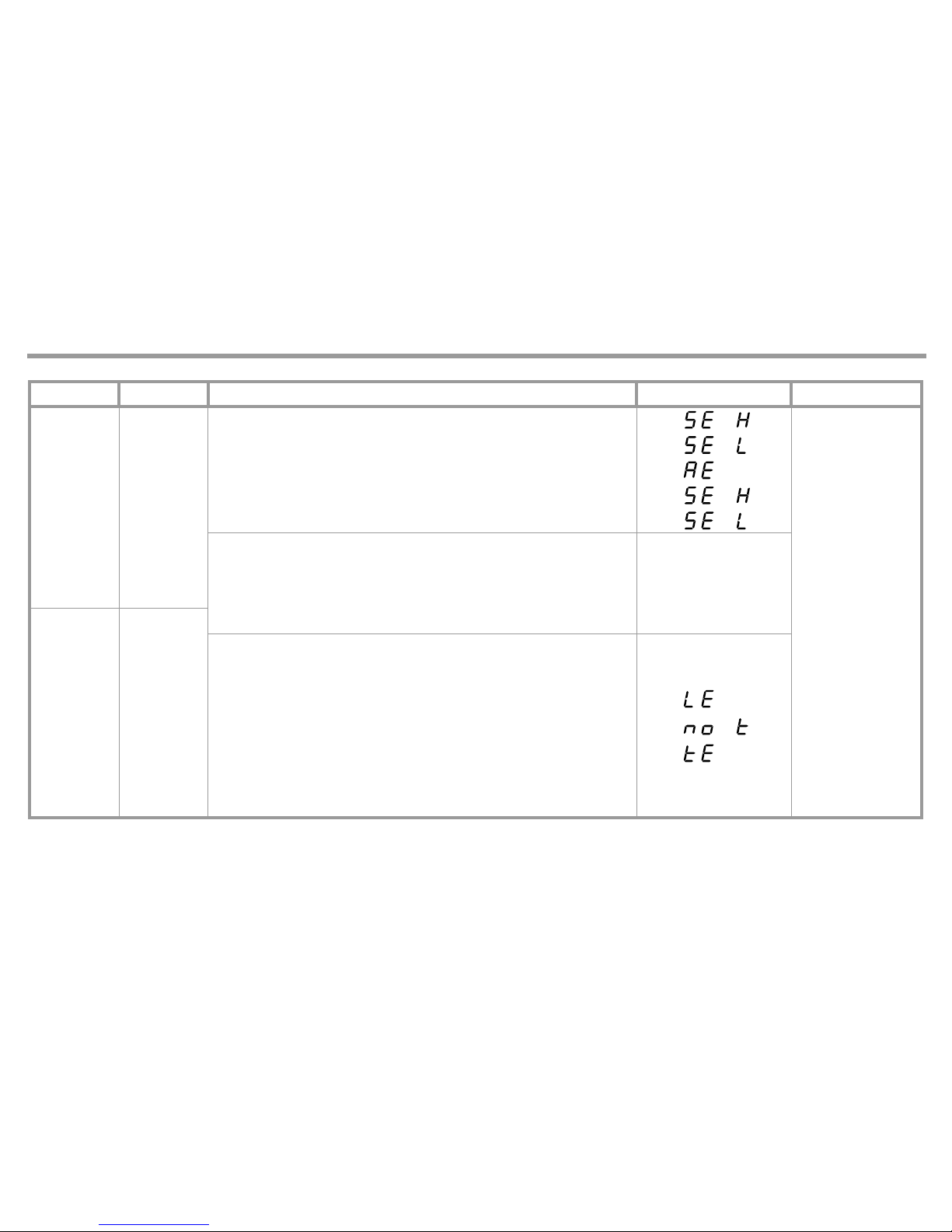
Character Bit No. Meaning Display on equipment Remark
1.
0 Sensor breakage measuring circuit 2
Status error word 1
(control loop)
1 Wrong polarity measuring circuit 2
2 Analog error
3 Sensor breakage measuring circuit 1
4 Wrong polarity measuring circuit 1
5 Low limit 1 fallen below
Associated
data
display
flashes
6 Low limit 2 fallen below
7 High limit 1 exceeded
2.
8 High limit 2 exceeded
9
Impermissible parameter, see 2.5
1)
10
11
Error in heating circuit
1)
12
Error at start of self-optimizing
1)
13
Error during self-optimizing + stop
1)
14
15
Page 19

GMC-I Messtechnik GmbH 19
3.
0 Sensor error position readback
Error status word 2
(heating current
monitor, equipment)
1 Sensor error heating current
2
3
4 Heating current not "off" with positioning signal switched off
Current display
flashes
5
Heating current < 80 % of the set point of the heating current with active
positioning signal
6
7
4.
8
EEPROM error
2)
9
10 Function error of rotary button
11 Error of measured value calibration
12
13 Invalid combination of markings
14
15
1) These error bits are deleted after reading. With LE and/or tE , the control function is reactivated.
2) EEPROM error reset by setting the standard parameters with PI = 32h.
Page 20

GMC-I Messtechnik GmbH 20
3.5 Request data from R2601
This communication makes it possible to request all values, parameters, configurations, states and equipment markings.
Thereby, the data is individually addressed per parameter index. See section 4 for the complete list of all parameter indices.
3.5.1 Request an equipment specification
The parameter index lies between 30h and 3Fh. Thus the characters "from/to channel" and "receipt No." in the control and long set are omitted.
Example: Request for equipment marking having the address = 33 = 21h (see 4.4)
Request from master (control set, see 2.2):
Equipment response (long set, see 2.3):
See 2.4.2.2 for the contents of the function field (FF).
The "data block" consists of a character 26h as marking for the R2601 (see 4.4).
68h 03h 03h 68h 21h 89 30h DAh 16h
FF PI PS
68h 04h 04h 68h 21h „FF“ 30h 26h „PS“ 16h
PI
Data block
Page 21

GMC-I Messtechnik GmbH 21
3.5.2 Request for a temperature parameter, for example
The parameter index is not 3xh, thus the characters "from/to channel" and "receipt No." = 1, 1, 0 are contained in the control and long set.
Example: Request for the maximum selectable set point (SP H ) of the R2601 with address = 33 = 21h (see 4.1)
Request from master (control set, see 2.2):
Equipment response (long set, see 2.3):
See 2.4.2.2 for the contents of the function field (FF)
According to 4.1 and 2.4.4, the two characters of the data block (52h, 03h) result in:
SP H = 0352h = 850
If it is an equipment with marking B1 and configuration "sensor type" = 0 ... 6 and "sensor unit" = even number, the unit is C
(the configuration could be requested with PI = 32h and 33h).
68h 06h 06h 68h 21h 89 07h 01h 01h 00h B3h 16h
FF PI PS
68h 08h 08h 68h 21h „FF“ 07h 01h 01h 00h 52h 03h „PS“ 16h
PI
2 characters
Data block
Page 22

GMC-I Messtechnik GmbH 22
3.6 Send data to R2601
This communication makes it possible to set all parameters, configurations and operating states which can be changed via operation. Thereby, the data
is individually addressed per parameter index. See section 4 for the complete list of all parameter indices. There is no protection against overwriting.
The settings of the DIP switches for disabling of the configuration and/or parameter setting are of no importance. Also the start of optimizing cannot be
disabled.
The R2601 checks the transmitted value for its setting range. Should it be beyond its permissible range, it is not stored, the bit "impermissible value" is
set in error status word 1, and the "service request" bit is set in the acknowledgement short set.
Same as with manual operation of the equipment, it must be noted, that a complete configuration must be made before parameters are set: That is, the
"control instructions" and "equipment specifications" must first be transmitted which influence the presentation of the "temperature parameters" (see
4.3 and 4.4).
3.6.1 Sending an equipment specification
The parameter index lies between 30h and 3Fh. Thus the characters "from/to channel" and "receipt No." are omitted in the long set.
Example: Setting the thermocouple type "K" on the equipment having the address = 0 (see 4.4).
Request from master (long set, see 2.3):
68h 05h 05h 68h 00h 69 33h 02h 00h 9Eh 16h
FF PI PS
Data block
Page 23

GMC-I Messtechnik GmbH 23
See 2.4.2.2 for the contents of the function field (FF)
The first character of the data block is the configuration "sensor type". The second character (B marking) cannot be stored, but a character (any, e.g.
00h) must be sent.
3.6.2 Send a control parameter, for example
The parameter index (PI) is not 3xh, thus the characters "from/to channel" and "receipt No." = 1, 1, 0 are contained in the long set.
Example: Send the Heat proportional band Pb I = 2.3% to R2601 with the address = 1 (see 4.2).
Transmission from master (long set, see 2.3):
See 2.4.2.2 for the contents of the function field (FF)
According to 4.2 and 2.4.4, the two characters of the data block (17h, 00h) are calculated to be: Pb I in 0.1% = 23 = 0017h
Acknowledgement from equipment (short set): 10h 00h „FF“ „FF“ 16h
PS
68h 08h 08h 68h 01h 69 10h 01h 01h 00h 17h 00h 93h 16h
FF PI PS
Acknowledgement from equipment (short set): 10h 01h „FF“ „FF“ + 1 16h
PS
Data block
Page 24

GMC-I Messtechnik GmbH 24
4 Parameter indices of the equipment parameters
For a request and/or transmission of data from and/or to the R2601, not only the parameter index for the individual data but also the format and thus
the length of the data block in the long set are of interest. From the column "Format" of the parameter tables and section 2.4.4, the number, order and
contents of the characters of the data block can be found.
See the operating instructions for detailed information on the function of the data.
4.1 Temperature parameters
The temperature parameters are combined in the main parameter group 0.
In the R2601, they are stored in standardized form to the measuring range so that other values result when the sensor type or the unit of measure is reconfigured, or when a change is made from fixed value or slave controller to differential controller.
4.1.1 Table of temperature parameters
X1 = range span, X2 = upper range limit, MBU = X2 - X1, see 4.1.3
PI Parameter Display Format Unit Setting range Remarks
00h Set point 15 bits (4.1.2) SP L... SP H
01h High limit for relay A1 15 bits (4.1.2) 0 = oFF, 1... MBU At rel. limit
X1 = oFF, X1 + 1 ... X2 At abs. limit and
fixed value controller
–MBU/2 = oFF,
–MBU/2 + 1 ... +MBU/2
At abs. limit and
differential controller
02h Low limit for relay A1 15 bits (4.1.2) Same as PI = 01h Same as PI = 01h
03h Second set point 15 bits (4.1.2) SP L ... SP H
Page 25

GMC-I Messtechnik GmbH 25
04h High limit for relay A2 15 bits (4.1.2) Same as PI = 01h Same as PI = 01h
05h Low limit for relay A2 15 bits (4.1.2) Same as PI = 01h Same as PI = 01h
06h Low set point 15 bits (4.1.2) X1 ... SP H For fixed value controller,
slave controller
–MBU/2 ... SP H For differential controller
07h High set point 15 bits (4.1.2) SP L ... X2 For fixed value controller,
slave controller
SP L ... MBU/2 For differential controller
08h Lower range limit standard signal 15 bits –1500 ... rn H For B2, B4, B5
09h Upper limit standard signal 15 bits rn L....9999 For B2, B4, B5
0Ch Calibration actual value 15 bits (4.1.2) –MBU/4 ... +MBU/4 For B1, B3, B4 and TC
–MBU/4 = Auto,
–MBU/4 + 1 ... MBU/4
For B1, B3, B4 and Pt100
0Dh Location of decimal point 8 bits
1)
0, 1 = 9.999, 2 = 99.99,
3 = 999.9, 4 = none
For B2, B5
0Eh Ramp for rising set points 15 bits
2)
0 = oFF, 1 ... MBU
0Fh Ramp for falling set points 15 bits
2)
0 = oFF, 1 ... MBU
1) The decimal point is for the display on the R2601 only, not for the parameter values.
2) Unit per minute, see 4.1.2 for units
Page 26

GMC-I Messtechnik GmbH 26
4.1.2 Unit of the temperature parameters
The unit of the temperature parameters depends upon
– the range marking B1 ... B5 of the equipment (see PI = 33h),
– the configured sensor type (see PI = 33h) and
– the configured unit of the sensor (see PI = 32h).
With standard signal (B2, B5) and Pt100 with 0.1display, the decimal point only serves for the display on the R2601, not for the parameter values.
That is, a value of 234.5 in the display, for example, is to be transmitted as 2345 = 0929. The two characters of the data block then are 29h, 09h.
Marking
Sensor type
0 ... 7 8
B1, B3, B4 1C / 1F0.1C / 0.1F
B2, B5 1, 0.1, 0.01, 0.001
Page 27

GMC-I Messtechnik GmbH 27
4.1.3 Table of measuring ranges
Sensor type Lower range limit X1 Upper range limit X2 Range span MBU
Code Kind Type in °C in °F in °C in °F in °C in °F
0
TC
J –18 0 850 1562 868 1562
1 L –18 0 850 1562 868 1562
2 K –18 0 1200 2192 1218 2192
3 B 0 32 1820 3308 1820 3276
4 S –18 0 1770 3218 1788 3218
5 R –18 0 1770 3218 1788 3218
6 N –18 0 1300 2372 1318 2372
7
Pt100
1 display –100 –148 500 932 600 1080
80.1 display –100.0 –148.0 500.0 932.0 600.0 1080.0
0
Standard
signal
0 ... 20 mA / 0 ... 10 V
rn L rn H rn H – rn L
1 4 ... 20 mA / 2 ... 10 V
Page 28

GMC-I Messtechnik GmbH 28
4.2 Control parameters
The control parameters are listed in the main parameter index group 1.
4.2.1 Table of the control parameters
PI Parameter Display Format Unit Setting range Remarks
10h Proportional band Heat 16 bits 0.1% 1 ... 9999
11h Proportional band Cool 16 bits 0.1% 1 ... 9999
12h Deadband 16 bits (4.1.2) 0 ... MBU
14h Delay time of the controlled system 16 bits 1 s 0 ... 9999
15h Output cycle time 16 bits 0.5 s 1 ... 1200
16h Regulation ratio for positioner mode 7 bits 1% –100 ... 100 For A2, A3, A4
0 ... 100 For A1
18h Motor running time 16 bits 1 s 5 ... 5000
1Dh Maximum regulation ratio 7 bits 1% –100 ... 100 For A2, A3, A4
0 ... 100 For A1
1Eh Regulation ratio with sensor error 7 bits 1% –100 ... 100 For A2, A3, A4
0 ... 100 For A1
1Fh Switching hysteresis for alarms
and limit monitor
8 bits (4.1.2) 0 ... 1.5%MBU
Page 29

GMC-I Messtechnik GmbH 29
4.3 Control instructions
The control instructions in main group 2 of the parameter index define the control action of the equipment
4.3.1 Table of the control instructions
PI Parameter Format Unit Setting range Remarks Contents
20h Control status control channel 16 bits Bit field See 4.3.2 Controller type (= CnF1,
2nd digit), SP 2 active?
Start/Stop self-optimizing
21h Error status
Control loop / HÜ (htg. current
monitor) / equipment
2x16 bits Bit field See 3.4
event data
Read only Summary of all error messages
22h Configuration
2nd signal input
8 bits See 4.3.3 Influences the display
of the temperature
parameters
CnF2, 2nd digit
Fixed value, differential,
slave controller
input range with standard signal
23h Automatic mode
Off and/or manual mode
8 bits AAh = Automatic,
manual via
binary input 2
55h = Off / manual
28h Manual regulation ratio
with manual mode
7 bits 1% –100 ... 100 For A2, A3, A4 Writing only permitted in
manual mode
0 ... 100 For A1
Page 30

GMC-I Messtechnik GmbH 30
4.3.2 Control status controller channel (PI = 20h):
Bit No. Value Meaning Remarks
2 - 0
000
001
010
011
Controller type =
Limit monitor
Positioner
Two-state controller Heat / continuous controller falling characteristic
Two-state controller Cool / continuous controller rising characteristic
100
101
110
Three-state controller / split range controller
Three-state controller Water cooling
Step controller
Not for marking A1
111 Impermissible
3 - 6 0
70 / 1SP active / SP 2 active Read only
80
90 / 1
Self-optimizing Stop / Start
Not for controller types 000, 001
1)
1) Otherwise bit 12 "Error at start of self-optimizing" will be set in error status word 1 (see 3.4)
10 0
11 0 / 1
Binary input 2 open / closed
2)
2) Standard: switch-over automatic / manual mode
Read only
12 - 15 0
Page 31

GMC-I Messtechnik GmbH 31
4.3.3 Configuration of the 2nd signal input (PI = 22)
Function signal input 2 Standard signal 2
Code B3 B4 B5 B4, B5
0 Fixed value controller (internal set point)
0 ... 20 mA
0 ... 10 V
1 Differential controller Fixed value controller Differential controller
2–
Slave controller
3–
4 – Fixed value controller
4 ... 20 mA
2 ... 10 V
5 – Fixed value controller Differential controller
6–
Slave controller
7–
Page 32

GMC-I Messtechnik GmbH 32
4.4 Equipment specifications
The equipment specifications in main group 3 of the parameter index among others include marking identification, software version and some configurations.
4.4.1 Table of equipment specifications
PI Parameter Format Unit Setting range Remarks
30h Equipment marking 8 bits 26h Read only
31h Marking identification 8 bits Bit field (4.4.2) Read only
32h Configuration
Sensor unit, continuous output
8 bits (4.4.3) CnF1, 4th digit
33h Sensor type, B marking 2x8 bits (4.4.4) CnF1, 3rd digit
35h Software version 8 bits e.g. 18h = version 1.8 Read only
36h Configuration of alarms 1 / 2 8 bits Bit field (4.4.5) CnF1, 1st digit
CnF2, 1st digit
39h Configuration of
switching outputs I / II
8 bits Bit field Value I II Read only
(DIP switch)
00h
08h
10h
18h
Transistor
Relay
Transistor
Relay
Transistor
Transistor
Relay
Relay
3Ah Continuous signal Cont 8 bits 0 = actual set point
1 = Cool reg. ratio (instead of II)
Only active, if PI = 32h
set to 8
3Fh OEM version number 8 Bit 0 = no OEM version Read only
Page 33

GMC-I Messtechnik GmbH 33
4.4.2 Marking identifications (PI = 31h)
Bit No. Value Meaning Remark
2 ... 0
001
100
101
111
A4
A1
A2
A3
5 ... 3
010
011
100
101
111
B2
B1
B5
B4
B3
Different from PI = 33h
60
7
01Series version
OEM version of hardware and software
Page 34

GMC-I Messtechnik GmbH 34
4.4.3 Configuration: Sensor unit, continuous output (PI = 32h)
Code
Sensor unit
1)
1) When switching-over, the physical quantity of the temperature parameter is preserved
Continuous output
Code Function
Note
Output range Output quantity
0Dh
The current setting
2)
is
stored as a user defined
default setting.
2) Configuration digits and all parameters except for the interface address Addr.
Configuration in accordance
with customer specifications
(K9) is stored at this location
and is thus overwritten.
0 C
0 ... 20 mA
0 ... 10 V
Actual value
(switching controller)
1 F
2 C
4 ... 20 mA
2 ... 10 V
3 F
0Eh
The user defined default setting
2)
is uploaded.
If a setting has never been
previously stored with d, the
factory default setting or the
configuration in accordance
with customer specifications
(K9) is uploaded.
All entries are overwritten,
including the results of selfoptimization and calibration.
4 C
0 ... 20 mA
0 ... 10 V
Regulation ratio
(continuous controller)
5 F
6 C
4 ... 20 mA
2 ... 10 V
7 F
8 C
0 ... 20 mA
0 ... 10 V
Select
output quantity
with Cont (PI = 3Ah)
9 F
0Ah C
4 ... 20 mA
2 ... 10 V
0Fh
The factory default setting
2)
is uploaded.
0Bh F
0Fh
Activate default configuration + default parameters
Page 35

GMC-I Messtechnik GmbH 35
4.4.4 Sensor type, B marking (PI = 33h)
1st character = sensor type: 2nd character = B marking:
Code
Sensor type
1)
1) A change influences the presentation of the temperature parameters
Value Meaning Remarks
Type Kind Condition 0 B5
Read only,
different from
PI = 31h
0J
Thermocouple
For signal input 1
at marking B1, B4
For both signal inputs
at marking B3
1B4
1L 3B3
2K 6B2
3B 7B1
4S
5R
6N
71 display
Pt 100
80,1 display
0 0 ... 20 mA / 0 ... 10 V
Standard signal
For signal input 1
at marking B2, B5
1 4 ... 20 mA / 2 ... 10 V
Page 36

GMC-I Messtechnik GmbH 36
4.4.5 Configuration of alarms 1 / 2 (PI = 36h)
Bit No. Alarms 1
3 ... 0
Code
1)
Start-up suppression Contact Heating circuit monitor
0 Relative
Inactive
NOC
Inactive
1 Absolute
2 Relative
Active
3 Absolute
4 Relative
Inactive
NCC
5 Absolute
6 Relative
Active
7 Absolute
8 Relative
Inactive
NOC
Active
9 Absolute
0Ah Relative
Active
0Bh Absolute
0Ch Relative
Inactive
NCC
0Dh Absolute
0Eh Relative
Active
0Fh Absolute
6 ... 4 Alarms 2
Page 37

GMC-I Messtechnik GmbH 37
4.5 Heating current monitor
Main group 6 of the parameter index includes the parameters for heating current monitoring.
4.5.1 Table of the parameters for the heating current monitor
0 Relative
Inactive
NOC
1 Absolute
2 Relative
Active
3 Absolute
4 Relative
Inactive
NCC
5 Absolute
6 Relative
Active
7 Absolute
7 0
1) A change between relative and absolute changes the numeric values of the high and low limits.
PI Parameter Display Format Unit Setting range Remarks
60h Set point of the heating current 15 bits 0.1 A 0 = Off, 1 ... A H
64h Upper range limit for
heating current
15 bits 0.1 A 10 ... 999 Current value at which 10 V
DC are applied to the input
Page 38

GMC-I Messtechnik GmbH 38
5 Storage operations
To store all parameter and configuration data of an equipment, it is not required to address all data individually via parameter indices. It is possible
instead to directly read and/or write all data stored in the non-volatile data memory (EEPROM) in one record.
This function serves to save the data, to quickly load or duplicate user-specific settings to the R2601. Length and format of the data block depends
upon the EEPROM allocation which can change with the software version of the R2601. That is why no information is given about it. Loading of a record
to the R2601 can, therefore, only be made for the same software version.
5.1 Request a record
Make the request as described in 3.5, the parameter index = D8h.
Example: Equipment address = 4
Request from master (control set, see 2.2):
Response from R2601 (long set):
68h 06h 06h 68h 04h 89h D8h 01h 01h 00h 67h 16h
FF PI PS
68h L + 6 L + 6 68h 04h „FF“ D8h 01h 01h 18h Data block „PS“ 16h
PI
Software version
L character
Page 39

GMC-I Messtechnik GmbH 39
5.2 Send a record
The long set for sending to the R2601 can practically only be generated from the received long set at the request of a record. The function field (6th
character) in 69h (write data) must be changed for that purpose. When copying to another R2601, the equipment address must be adapted (5th character). Following, the checksum (last but one character) must be corrected.
Send from master (control set, e.g. equipment address = 4):
Reply from R2601 (short set):
The record will only be accepted by the equipment, when the software version (12th character) and the length of the data block agree with the equipment. The content of the data block is not checked as it is correct in itself when it comes from a R2601.
It must be noted to send a record only to an equipment having the same A and B markings as the equipment from which the record comes. If this is not
observed (e.g. by impermissible configuration data) an unreasonable action of the R2601 may result which can be dangerous to the system.
68h L + 6 L + 6 68h 04h 69h D8h 01h 01h 18h Data block „PS“ 16h
FF PI
10h 04h „FF“ „FF“ + 4 16h
L character
Page 40

Edited in Germany • Subject to change without notice • A pdf version is available on the internet
GMC-I Messtechnik GmbH
Südwestpark 15
90449 Nürnberg •
Germany
Phone +49 911 8602-111
Fax +49 911 8602-777
E-Mail info@gossenmetrawatt.com
www.gossenmetrawatt.com
 Loading...