

Page 1
Operating Instructions
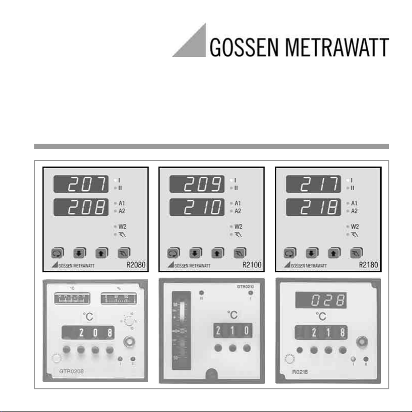
R2080, R2100, R2180
Compact Controller 96 x 96 mm
3-349-219-15
2/9.02
Page 2

Contents Page Page
Safety Features and Precautions . . . . . . . . . . . . . . . . .3
Maintenance . . . . . . . . . . . . . . . . . . . . . . . . . . . . . . . .3
Repair and Replacement Parts Service . . . . . . . . . . . . .4
Product support . . . . . . . . . . . . . . . . . . . . . . . . . . . . .4
Identification of Controller R2080 . . . . . . . . . . . . . . . . .5
Identification of Controller R2100 . . . . . . . . . . . . . . . . .6
Identication of Controller R2180 . . . . . . . . . . . . . . . . . .7
Mechanical Installation / Preparation . . . . . . . . . . . . . .8
Differences between R2080/R2100/R2180 and
GTR0208/GTR0210/GTR0218 . . . . . . . . . . . . . . . . . . . 9
Connection R2080 . . . . . . . . . . . . . . . . . . . . . . . . . .10
Connection R2100 . . . . . . . . . . . . . . . . . . . . . . . . . .11
Connection R2180 . . . . . . . . . . . . . . . . . . . . . . . . . .12
Electrical Connection . . . . . . . . . . . . . . . . . . . . . . . . .13
Performance After Activating Auxiliary Voltage . . . . . .13
Display – Setpoint Selection – Operation . . . . . . . . . .14
Operating Flowchart . . . . . . . . . . . . . . . . . . . . . . . . .15
Parameters Configuration . . . . . . . . . . . . . . . . . . . . .16
Limit Value Monitoring . . . . . . . . . . . . . . . . . . . . . . . .17
Adjusting Control Performance – Manual Self-Tuning .18
Self-Tuning . . . . . . . . . . . . . . . . . . . . . . . . . . . . . . . .21
Alarms . . . . . . . . . . . . . . . . . . . . . . . . . . . . . . . . . .22
Error Messages . . . . . . . . . . . . . . . . . . . . . . . . . . . . .22
Setpoint Ramps . . . . . . . . . . . . . . . . . . . . . . . . . . . .24
Balancing . . . . . . . . . . . . . . . . . . . . . . . . . . . . . . . . .24
Configuration . . . . . . . . . . . . . . . . . . . . . . . . . . . . . .25
Saving and Loading Device Settings . . . . . . . . . . . . . .28
Manual Operation with Binary Input . . . . . . . . . . . . . .29
PWR Out Offset with Binary Input . . . . . . . . . . . . . . . .29
Heating Current Monitoring . . . . . . . . . . . . . . . . . . . . 30
Heating Circuit Monitoring . . . . . . . . . . . . . . . . . . . . . 30
Technical Data . . . . . . . . . . . . . . . . . . . . . . . . . . . 31
Meanings of symbols on the instrument
Indicates EC conformity
Continuous doubled or
reinforced insulation
Warning concerning a source of danger
Attention: observe documentation!
Functional earth terminal,
earthing for functional purposes only
(no safety function)
2 GOSSEN METRAWATT GMBH
Page 3

Safety Features and Precautions
The R2900 controller is manufactured and tested in accordance with safety regulations IEC 61010-1 /
DIN EN 61010-1 / VDE 0411-1.
If used for its intended purpose, safety of the user and of the device is assured.
Read the operating instructions completely and carefully before using the device, and follow all instructions included
therein. The operating instructions should be made available to all users.
Observe the following safety precautions:
– The device may only be connected to electrical systems which comply with the specified nominal range of
use (see circuit diagram and serial plate), and which are protected with a fuse or circuit breaker with a
maximum nominal current rating of 16 A.
– The installation must include a switch or a circuit breaker which serves as a disconnecting device.
The controller may not be used:
– If visible damage is apparent
– If it no longer functions flawlessly
– After lengthy periods of storage under unfavorable conditions (e.g. humidity, dust, temperature)
In such cases the device must be removed from service and secured against any possible inadvertent use.
Maintenance
Housing
No special maintenance is required for the housing. Keep outside surfaces clean. Use a slightly dampened
cloth for cleaning. Avoid the use of solvents, cleansers and abrasives.
Repair and Parts Replacement
Repairs and the replacement of parts conducted at a live open instrument may only be carried out by trained
personnel who are familiar with the dangers involved.
GOSSEN METRAWATT GMBH 3
Page 4

Repair and Replacement Parts Service
When you need service, please contact:
GOSSEN METRAWATT GMBH
Service-Center
Thomas-Mann-Straße 20
D-90471 Nürnberg
Telefon +49-(0)-911-86 02-410/256
Telefax +49-(0)-911-86 02-253
E-Mail service@gmc-instruments.com
This address is only valid in Germany.
Please contact our representatives or subsidiaries for service in other countries.
Product support
When you need support, please contact:
GOSSEN METRAWATT GMBH
Hotline Produktsupport
Telefon +49-(0)-911-8602-112
Telefax +49-(0)-911-8602-709
E-Mail support@gmc-instruments.com
4 GOSSEN METRAWATT GMBH
Page 5

Identification of Controller R2080
Feature
Electronic PDPI controller R2080
Controller types
2-step controller medium time response A01
2-step controller with limit contact medium time response A02
3-step controller medium time response A04
2-step controller short time response A11
2-step controller with limit contact short time response A12
3-step controller short time response A14
without feedback with 1 limit contact A21
without feedback with 2 limit contacts A22
Designation
Measuring ranges
Thermocouple type L Fe-CuNi 0 … 200 °CC01
type J Fe-CuNi 0 … 200 °CC04
type K NiCr-Ni 0 … 400 °CC08
type R Pt13Rh-Pt 0 … 1600 °CC12
Resistance thermometer Pt100 0 … 100 °CC20
Output type 1
Relay D1
Tra ns is tor D2
type S Pt10Rh-Pt 0 … 1600 °CC13
st
switching point
0 … 400 °CC02
0 … 600 °CC03
0 … 400 °CC05
0 … 600 °CC06
0 … 800 °CC07
0 … 600 °CC09
0 … 800 °CC10
0 … 1200 °CC11
0 … 200 °CC21
0 … 400 °CC22
–100 … +100 °CC24
–100 … +200 °CC25
Features A3, A13, C23 and E3 of controller GTR0208
cannot be replaced.
Feature B2 is not compatible with GTR0208.
Auxiliary voltage is generally AC 110 … 230 V.
A switch to deactivate the control outputs is always
available (see feature F1 of controller GTR0208).
Generally, the actual value and the setpoint value and/
or heating current are indicated.
As a rule, setpoint limiting is available.
GOSSEN METRAWATT GMBH 5
Page 6

Identification of Controller R2100
Feature
Electronic PDPI controller R2100
Controller types
2-step controller A1
3-step controller A2
Time response
medium XB0
short XB1
long XB2
Measuring range
Thermocouple type L Fe-CuNi 0 … 400 °CC01
type J Fe-CuNi 0 … 400 °CC03
type K NiCr-Ni 0 … 400 °CC05
type R Pt13Rh-Pt 0 … 1600 °CC09
Resistance thermometer Pt100 0 … 100 °CC20
Direct current 0 … 5 mA C30
Output type 1
Relay D1
Transistor D2
Limit contact
none G0
MIN / MAX G1
Rupture protection
direct action XH0
reverse action XH1
type S Pt10Rh-Pt 0 … 1600 °CC10
0 … 20 mA, display 0.00 … 2.00 C32
st
switching point
0 … 800 °CC02
0 … 600 °CC06
0 … 800 °CC07
0 … 1200 °CC08
0 … 200 °CC21
0 … 400 °CC22
–100 … +200 °CC24
0 … 20 mA C31
Designation
Features C23 and E5 of controller GTR0210 cannot be
replaced.
Auxiliary voltage is generally AC 110 … 230 V.
A switch to deactivate the control outputs and a
switching facility for the display is always available
(see features F1 and F2 of controller GTR0210).
6 GOSSEN METRAWATT GMBH
Page 7

Identication of Controller R2180
Feature
Electronic PDPI controller R2180
Controller types
2-step controller A1
3-step controller A2
2-step controller with MAX limit contact A3
2-step controller with MAX / MIN limit contact A4
Time response
short B1
medium B2
long B3
Measuring range
Thermocouple °C type L Fe-CuNi 0 … 199 °CC01
0 … 399 °CC02
0 … 599 °CC03
type J Fe-CuNi 0 … 199 °CC04
0 … 399 °CC05
0 … 599 °CC06
32 … 392 °FC13
32 … 752 °FC14
32 … 1112 °FC15
type K NiCr-Ni 0 … 399 °CC07
0 … 599 °CC08
0 … 799 °CC09
0 … 1200 °CC10
32 … 752 °FC16
32 … 1112 °FC17
32 … 1472 °FC18
32 … 2192 °FC19
type R Pt13Rh-Pt 0 … 1600 °CC11
32 … 2912 °FC20
type S Pt10Rh-Pt 0 … 1600 °CC12
32 … 2912 °FC21
Designation
Feature
Resistance thermometer Pt100 –99,9 … + 99,9 °CC30
(2-wire connection) –99,9 … +199,9 °CC31
Resistance thermometer Pt100 –99,9 … + 99,9 °CC50
(3-wire connection) –99,9 … +199,9 °CC51
Output type 1
Relay D1
Tra ns is tor D2
st
switching point
0 … +99,9 °CC32
0 … +199,9 °CC33
0 … +399,9 °CC34
–148 … + 212 °FC37
–148 … + 392 °FC38
32 … 212 °FC39
32 … 392 °FC40
32 … 752 °FC41
0 … +99,9 °CC52
0 … +199,9 °CC53
0 … +399,9 °CC54
–148 … + 212 °FC57
–148 … + 392 °FC58
32 … 212 °FC59
32 … 392 °FC60
32 … 752 °FC61
Designation
Features C35, C42, C55, C62 and E1 of controller
GTR0218 cannot be replaced.
Auxiliary voltage is generally AC 110 … 230 V.
A switch to deactivate the control outputs is always
available (see feature F1 of controller GTR0218).
GOSSEN METRAWATT GMBH 7
Page 8
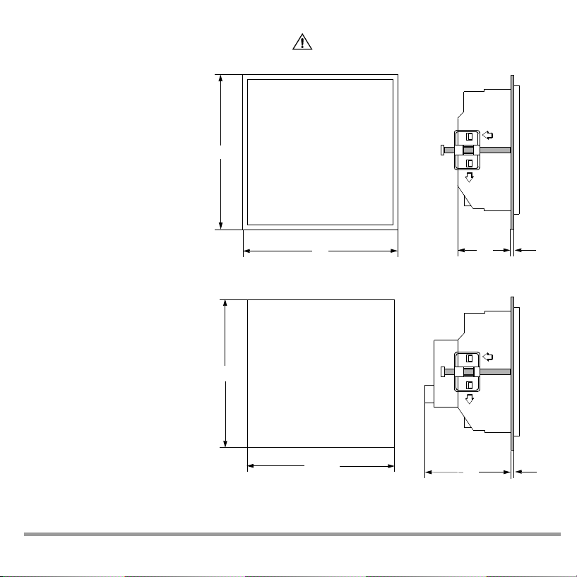
Mechanical Installation / Preparation
The RXX0 controller is intended for installation to a control panel. The installation location should be vibration-free to the
greatest possible extent. Aggressive vapors
shorten the service life of the controller.
Requirements set forth in VDE 0100 must
be observed during the performance of all
work. Work on the device may only be carried out by trained personnel who are familiar with the dangers involved.
Set the housing into the panel cutout from
the front, and secure it from behind at the
left and right-hand sides with the two included screw clamps.
Push the screw clamps first all the way up
to the limit stop in direction 1 and subsequently in direction 2 for this purpose.
Typical tightening torque amounts to
10 Ncm, and a value of 20 Ncm should not
be exceeded.
In general, unobstructed air circulation
must be assured when one or several devices are installed. The ambient temperature underneath the devices may not exceed 50 °C.
96
+0,8
92
Panel cutout
1
2
96
R2080, R2180 and R2100 G0
50
5
1
2
+0,8
92
8 GOSSEN METRAWATT GMBH
70
R2100 G1 only
5
Page 9

Differences between R2080/R2100/R2180 and GTR0208/GTR0210/GTR0218
Controllers R2080, R2100 and R2180 do not supersede analog devices GTR0208, GTR0210 and GTR0218 in
a fully compatible manner. Please note the following deviations:
Temperature sensor Pt100
As a rule, controllers R2080, R2100 and R2180 are provided with a 3-wire-connection.
Consequently, for Pt100 (but not in the case of a thermocouple), terminals 18-19 at controllers R2080 / R2100
or terminals 12-13 at controller R2180 must be shunted.
Sensor rupture protection
Controllers R2080, R2100 and R2180 are able to detect a broken sensor and/or polarity reversal of the sensor,
whereupon the actuating outputs are deactivated and an alarm is triggered at the same time.
If the actuating outputs are to assume a certain status, it must be set with parameter Y SE.
Protective conductor connection
According to EMC requirements controllers R2080, R2100 and R2180 must be provided with a protective conductor connection.
Cooling output
In the case of 3-step controllers R2080 / R2180, the 2
Limit contact
In the case of controller types R2080 / R2180 with limit contact, the configuration of the R2080 / R2180 must
be changed from CnF1 = 0xx0 to 0xx4 while using the break contact (reverse action principle). Switching point
distance ∆w can only be set as a relative MAX alarm to a value above zero for the R2080 / R2180.
Heating current display / monitoring
Heating current transformer GTY 2570 127 R0x can no longer be used in connection with R2080.
Instead, 3-input and/or 4-input current transformers GTZ 4121 must be fitted for acquiring heating current.
This offers the additional feature of not only indicating the heating current but also monitoring antivalence pro-
vided the R2080 has been appropriately set. In this case, an alarm is triggered if current is too low while heating
is activated or if current is not „off“ while heating is deactivated (see also page 30).
RC elements
In contrast to GTR0210, no RC elements for spark suppression have been fitted in controllers R2080, R2100
and R2180. It is therefore recommended retrofitting the controlled actuators (contactors, solenoid valves, etc.)
with the associated RC elements.
nd
switching point cannot be used as an NC contact.
GOSSEN METRAWATT GMBH 9
Page 10
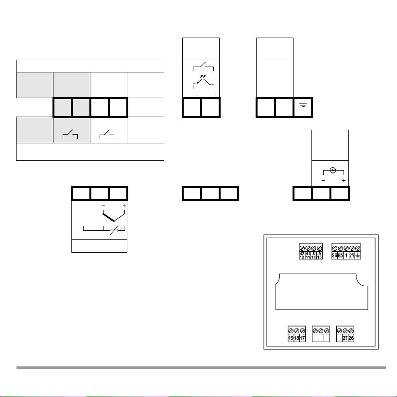
Connection R2080
Binary
Input
Transistor Output for Controlling SSRs 110 - 230
D2 – + I – + II
421241118149
D1
I
II
Switching Output
19 18 17 27 26
Sensor
A01, A11,
A21
15
A02, A04,
A12, A14,
A22
86 85 1 2/3
Auxiliary
Voltage
V∼
NL
Heating
Current
Tra ns f.
10 GOSSEN METRAWATT GMBH
Page 11

Connection R2100
Binary
Input
Transistor Output for Controlling SSRs 110 - 230
D2 – + I – + II A1
421241
D1 A2
Switching Output
89 8685 12/3
11
I
II
19 18 17 16 15
C01 ... C24
10 V
C30, C31
20 mA
Sensor
Auxiliary
Voltage
V∼
NL
Heating
Current
Tra ns f.
62 63 61 60
A1 A2
G1
Alarms
GOSSEN METRAWATT GMBH 11
Page 12

Connection R2180
Binary
input
Transistor Output for Controlling SSRs 110 - 230
D2 – + I – + II A1
D1
48824781435742
I
Switching Output
13 12 11 16 15
Sensor
58
II
A2, A3,
A4
86 85 N L
Auxiliary
Voltage
V∼
NL
Heating
Current
Tra ns f.
12 GOSSEN METRAWATT GMBH
Page 13

Electrical Connection
Connectors: Screw terminals for wire with a cross section of 1.5 square mm or
Tighten screws with a manual screwdriver only! Tightening torque for all screw terminals: max. 0.6 Nm
EN 55022 requires the following warning as regards electromagnetic compatibility:
This is a class A device. It may cause radio interference in residential surroundings. If this is the
two-core wire-end ferrules with a cross-section of 2 x 0.75 square mm
Warning
case, the operator may be required to implement appropriate corrective measures.
Performance After Activating Auxiliary Voltage
LED Segment Test
U/M Software Version
approx. 2 s
Current Configuration
CnF1
Hardware Designation
approx. 1.5 s
Current
Configuration
GOSSEN METRAWATT GMBH 13
G Designation
CnF2
Actual Value
Setpoint or oFF
approx. 1.5 s
Page 14

Display – Setpoint Selection – Operation
Actual value
Setpoint value / PWR (pulse width ratio)
Press briefly:
Shift setpoint value ↔ PWR
Press and hold:
Changeover to parameter level
(see operating flowchart)
Up and down scrolling keys for setpoint value
selection (and parameter setting)
The value is changed directly. After 2,5 s or after
pressing key , the value is stored to memory and
becomes active.
This is acknowledged by a brief blackout of the display.
GOSSEN METRAWATT
I
II
A1
A2
W2
Switching output I active
Switching output II active
Alarm(s) active
Setpoint 2 active
Off
R2XX0
Press and hold:
Switchover Off ↔ automatic operation
14 GOSSEN METRAWATT GMBH
Page 15

Operating Flowchart
Off
Act. val.
I
II
A1
A2
W2
PARAMETER LEVEL
Param. value
Param. value
Off
Act. val.
(page 16)
I
II
A1
A2
W2
Automatic Operation
Act. val.
Setpoint
I
II
A1
A2
W2
I
II
A1
A2
W2
I
II
A1
A2
W2
Setpoint can only
be selected here.
Act. val.
Heat. curr.
Only appears when heating
current monitoring is activated.
CONFIGURATION
I
II
A1
A2
W2
– no alarm function
– no error signalling
– The actuating outputs are inactive
unless keys are pressed.
OPERATING LEVEL
I
II
A1
A2
W2
(page 25)
Act. val.
PWR
W2
I
II
A1
A2
W2
I
II
A1
A2
Press key briefly
Press and hold key
until the display is switched
Press and hold both keys,
until display is switched
– By pressing key /
switching output I („heating“) /
II („cooling“) is directly controlled.
GOSSEN METRAWATT GMBH 15
Page 16

Parameters Configuration
X1 = lower range limit, X2 = upper range limit,
(see Configuration page 25), not to the C Designation.
Parameter Display Range Default Comment
Upper limit value for relay A1
Lower limit value for relay A1
Upper limit value for relay A2
Lower limit value for relay A2
Setpoint 2 SP L ... SP H X1
Ramp for rising setpoints oFF, 1 ... MBU pro min oFF
Ramp for falling setpoints oFF, 1 ... MBU pro min oFF
Heating current setpoint
(see Balancing)
Proportional band heating 0.1 ... 999.9 % 10.0 / *
Proportional band cooling 0.1 ... 999.9 % 10.0 / * Only with 3-step controllers
Dead band 0 ... MBU 0 Not with 2-step controllers
Path delay time 0 ... 9999 s 100 / *
Read-out cycle time 0.5 ... 600.0 s 10.0 / *
Motor run-time
Switching hysteresis
Maximum setpoint SP L ... X2 X2 / *
Minimum setpoint X1 ... SP H X1 / *
Maximum PWR –100 ... 100 % 100
Actual value correction
(see Balancing)
MBU = X2 – X1
oFF, 1 ... MBU
oFF, X1 ... X2
. These values refer to the configured sensor type
oFF / *
oFF / *
Auto, oFF, 0.1 ... A H oFF
5 ... 5000 s 60
0 ... 1,5% MBU 0,5 %MBU / *
(Auto), –MBU/4 ... +MBU / 4 0 / *
Relative (= default config.)
Absolute
Not with step-action
1)
controllers
Only with step-action
4)
controllers
For limit value monitoring and
limit transducers
Only with designations
C01 ... C24
2)
3)
16 GOSSEN METRAWATT GMBH
Page 17

Parameter Display Range Default Comment
Decimal point position 9999, 999•9, 99•99, 9•999 9999 / *
only for designations C30, C31Upper range limit, standard signal rn L ... 9999 100 / *
Lower range limit, standard signal –1500 ... rnH 0
Upper range limit, heating current
(see Balancing)
PWR for actuator mode, or for
PWR out offset
Sensor error PWR –100 ... 100 % 0 / *
1)
only where: “controller sort” configuration digit ≠ 6
2)
only where: “controller sort” configuration digit = 4 or 5
3)
only where: “controller sort” configuration digit = 0, 4, 5 or 6
4)
only where: “controller sort” configuration digit = 6
* the values have been preset to match the order features.
1.0 ... 99.9 A 42,7
–100 ... 100 % 0
not with step-action
controllers
1)
Parameters Pb 1 through yse are disabled for the operator during self-tuning.
Limit Value Monitoring
Alarm Relay n, NO Contact
Alarm Relay n, NC Contact
Hysteresis (HYSt)
ALnL ALnH
ALnL ALnH
Actual ValueSetpoint
n = 1, 2
Relative Limit Values
Absolute Limit Values
Actuation suppression: Alarm suppression remains inactive during actuation (configuration digit “alarms 1 and 2”)
until temperature has exceeded the lower limit value for the first time. During cooling, suppression is active until
temperature has fallen below the upper limit value for the first time. Suppression is active when auxiliary power
is activated, if the current setpoint is changed or setpoint 2 is activated, or if switching takes place from off to
automatic operation.
GOSSEN METRAWATT GMBH 17
Page 18

Adjusting Control Performance – Manual Self-Tuning
Parameters Pb 1, Pb 11, tu and tc are determined by means of manual self-tuning in order to maintain opti-
mized controller dynamics. An actuation test or an oscillation test is performed to this end.
Preparation
– Complete configuration (page 25) and parameters configuration (page 16) must first be entered for use of the
controller.
– The actuators should be deactivated with the off function (page 15).
–A recorder must be connected to the sensor and adjusted appropriately to prevailing circuit dynamics and
the setpoint.
– For 3-step controllers, on and off-time must be recorded for switching output I (e.g. with an additional
recorder channel or a stopwatch).
– Configure as limit transducer (controller sort = 0) (see page 25).
– Set read-out cycle time to the minimum value: tc = 0.5.
– Deactivate PWR limiting. YH = 100.
– Reduce (or increase) the setpoint so that overshooting and undershooting do not cause any impermissible
values.
Performing the Actuation Test
– dbnd = MRS Setting for 3-step controller (switching output II may not be triggered)
dbnd = 0 Setting for step-action controllers (switching output II must be triggered)
– Start the recorder.
– Activate the actuators with automatic operation.
– Record two overshoots and two undershoots.
The actuation test is now complete for 2-step and step-action controllers.
Continue as follows for 3-step controllers:
–Set dbnd to 0 in order to cause further overshooting with active switching output II. Record two overshoots
and two undershoots.
Record on-time T
and off-time TII at switching output I or the continuous output for the last oscillation.
I
18 GOSSEN METRAWATT GMBH
Page 19

∆
t
∆
x
P
x
ss
dbnd = 0dbnd = MRS
(3-step controller only)
T
T
I
II
Evaluating the Actuation Test
– Apply a tangent to the curve at the intersection of the actual value and the setpoint, or at the cut-off point of
the output.
– Measure time ∆t.
– Measure oscillation amplitude x
, or overshooting for step-action controllers ∆x.
ss
Parameter Values
tu 1,5
• ∆t ∆t – (tY / 4)
tc tu / 12 tY / 100
Pb 1 (x
Pb 11 – Pb 1
/ MRS) • 100 % (∆x / MRS) • 50 %
ss
• (T
/ TII)–
I
Parameter 2-step controller 3-step controller Step-action controller
MRS = Measuring range span of the configured sensor type (compare Configuration, see page 25), not the
measuring range according to C Designation
Performing the Oscillation Test
If an actuation test is not possible, for example if neighboring control loops influence the actual value too greatly,
if switching output II must be active in order to maintain the actual value (cooling operating point), or if optimization is required directly to the setpoint for any given reason, control parameters can be determined by means of
sustained oscillation. However, calculated values for tu may be very inaccurate in this case under certain circumstances.
– Same preparation as for actuation test. The test can be performed without a recorder if the actual value is
observed at the display, and if times are measured with a stopwatch.
GOSSEN METRAWATT GMBH 19
Page 20

– dbnd = 0 Setting for 3-step and step-action controllers
– Activate the actuators with automatic operation, and start the recorder if applicable. Record several
oscillations until they become uniform in size.
–Measure oscillation amplitude x
–Record on-time T
and off-time TII at switching output I for the oscillations.
I
.
ss
x
ss
T
T
I
II
Evaluating the Oscillation Test
Parameter Values
0,3 • (TI + TII)0,2 • (TI + TII – 2tY)
tu
1)
tc tu / 12 tY / 100
Pb 1 x
• 100 %
ss
MRS
Pb 11 – Pb 1
xss • TII • 100 %
MRS (T
+ TII)
I
• (T
/ TII)–
I
x
ss
• 50 %
MRS
Parameter 2-step controller 3-step controller Step-action controller
1) If either TI or TII is significantly greater than the other, value tu is too large.
Correction for step-action controllers in the event that TI or TII is smaller than tY:
tY
Multiply Pb 1 by , if T
• tY tY • tY
• T
T
I
is smaller, or by , if TII is smaller.
I
I
TII • T
II
The value for tu is very inaccurate in this case. It should be optimized in the closed loop control mode.
Closed Loop Control Mode
The closed loop control mode is started after self-tuning has been completed:
– Configure the desired control algorithm with controller sort.
–Adjust the setpoint to the required value.
– The dead band can be increased from dbnd = 0 for 3-step and step-action controllers if control of switching
output I and II changes too rapidly, for example due to an unsteady actual value.
20 GOSSEN METRAWATT GMBH
Page 21

Self-Tuning
Self-tuning is used to achieve optimized controller dynamics, i.e. parameters
Pb 1, Pb 11, tu and tc are determined.
Start
Slow Blinking
Abort
Current
Current
Current
or
– The controller is switched to the automatic operating mode after self-tuning has been successfully
completed.
– In the case of 3-step controllers (controller sorts 4 and 5), cooling is activated if the upper limit value is
exceeded in order to prevent overheating. Self-tuning then performs an oscillation test around the
setpoint.
Sequence
– The setpoint which is active when tuning is started remains valid and can no longer be changed.
– Activation or deactivation of setpoint 2 does not
– Selected setpoint ramps are not taken into consideration.
– If started at the operating point (actual value approximates the setpoint value), overshooting cannot be
avoided.
Abort
– Self-tuning can be aborted at any time with the keys (→ automatic operating mode), or by
switching to manual / off with the key.
– If an error occurs during self-tuning, the controller no longer reads out an actuating signal. Self-tuning must
be aborted in this case.
Additional information regarding error messages upon request.
I
Preparation
II
A1
– Complete configuration must be performed before
A2
W2
– The setpoint value is adjusted to the value which is required after
self-tuning is started.
self-tuning.
I
II
Start
A1
A2
– Briefly press the keys simultaneously at the operating level
W2
(automatic or off operating mode) in order to trigger self-tuning. Selftuning cannot be started in the “actuator” or “limit transducer” mode.
– tun1...tun8 blinks at the display at all operating levels during self-tuning.
become effective.
GOSSEN METRAWATT GMBH 21
Page 22

Alarms
Blinking Display Error Message Source Blinking
Display
Heating current Heating current monitoring LED A1 Output A1 activated
Actual value Limit value monitoring 1 LED A1 Output A1 activated
Actual value Limit value monitoring 2 LED A2 Output A2 activated
1)
only for R2100 G1
2)
only in the case of configuration as a 2-step controller
The display is switched to the operating level 30 seconds after value selection has been completed during configuration or parameter setting.
Output Comment
1)
or output II activated
or output II activated
2)
NO / NC contact defines in config-
1)
uration digits “alarms 1 and 2”
2)
LED blinks at all levels
1)
Error Messages
Responses in the event of an error:
1. In the case of R2100 G1 alarm output A1 is activated; output performance is determined by the “alarm 1”
configuration digit (see Configuration on page 25).
In the case of other controllers and designations and in the case of configuration as a 2-step controller,
read-out takes place at switching output II. LED II lights up when the relay contact II is closed and/or
transistor output II is active.
2. LED A1 blinks at all levels. The (blinking) error message only appears at the operating level: in the event of
faulty measured values at the display, at which the error-free measured value is otherwise displayed (SE H,
SE L and CE) while other error messages appear in the upper display.
3. The display is switched to the operating level 30 seconds after value selection has been completed during
configuration or parameter setting.
4. Exceptions and additional information are included in the following table:
22 GOSSEN METRAWATT GMBH
Page 23

Display
sensor error
high
sensor error
low
current error
no tune
tune error 2
loop error
parameter
error
digital error
Error Message Source Response
Broken sensor or actual value
Ctr. Sort PWR Read-Out
greater than upper range
limit
Sensor polarity reversed or
actual value less than lower
range limit
Current transformer has reversed polarity, is unsuitable
or defective
Self-tuning cannot be started
(controller sort: “actuator” or
“limit transducer”)
Disturbance in self-tuning
sequence in steps 1 through
13 (step 2 in this case)
Measured temperature rise is
too small with heat on at
100%
Parameter not within
permissible limits
Error detected by digital component monitoring
2 or 3-step
Step
On/off ctr.
Actuator No response to error
Same as heating current monitoring alarm
Continues to control temperature
No response to error
Error message is shown until key is pressed
Control outputs I and II inactive
Self-tuning must be aborted.
Control outputs I and II inactive.
Error message is not cleared until key is pressed
and held.
Control outputs I and II inactive.
The parameter level is disabled.
Control outputs I and II inactive
YSE = –100/0/100% YSE ≠ –100/0/100%
–100/0/100%
If the controller has settled in:
last “plausible” PWR, if not:
YSE
YSE
Hardware error detected by
analog error
1)
Avoid disturbances which impair the self-tuning sequence, e.g. sensor errors.
2)
Close the control loop: Check the sensor, the actuators and the heater for correct functioning.
Check sensor-heater assignments (wiring). Correctly optimize control parameters tu and Pb 1.
3)
Restore default configuration and default parameters, and then reconfigure, or load user-defined default settings.
analog component
monitoring
Control outputs I and II inactive
Remedy
Eliminate
sensor error
Inspect
current
transformer
–
1)
2)
3)
Arrange for
repair at
authorized
service
center
GOSSEN METRAWATT GMBH 23
Page 24

Setpoint Ramps
Function Parameters SPuP and SPdn cause a gradual temperature change
Activation – When auxiliary power is switched on
Setpoint display The targeted setpoint is displayed (not the currently valid setpoint) with a blinking r at the
Limit values Relative limit values make reference to the ramp, not the targeted setpoint. As a rule, no
(rising / falling) in degrees per minute.
– When the current setpoint is changed
– When setpoint 2 is activated
– After switching from manual to automatic operation
left-hand digit.
alarm is triggered for this reason.
Balancing
Thermocouple Correction (parameter: CAL)
The correction value is selected in °C or °F. The displayed correction value is added to the measured
temperature.
Cable Compensation for Pt 100 with 2-Wire Connection (parameter: CAL)
The correction value can be determined automatically in the “Off” mode:
– Short circuit the sensor at the measuring point.
–Set the CAL value to Auto.
Measured cable resistance is converted to temperature change and is entered as the CAL value.
Balancing can also be performed manually if the sensor temperature is known:
CAL = known sensor temperature – displayed temperature value
Scaling for Heating Current Monitoring (parameter: A H)
The default setting for the GTZ 4121 is 42.7 A. If the GTZ 4121 current transformer is not used for acquiring
heating current, the current value must be selected at which the utilized transformer generates an output
voltage of 10 V DC.
24 GOSSEN METRAWATT GMBH
Page 25

Configuration
(continued on following page)
Controller sort Alarm 1
Code Code
Limit transducer relative
Actuator absolute
2-step controller, heat relative
2-step controller, cooling absolute
3-step controller relative
3-step controller, water cooling absolute
Step-action controller relative
I
II
A1
A2
W2
I
II
A1
A2
W2
absolute
relative
absolute
relative
absolute
relative
absolute
relative
absolute
Actuation
Suppression
inactive
active
inactive
active
inactive
active
inactive
active
Contact
NO contact
NC contact
NO contact
NC contact
Heating Circuit
Monitoring
inactive
active
GOSSEN METRAWATT GMBH 25
Page 26

Configuration
(continued)
I
II
A1
A2
W2
Sensor Unit of
Measure
Code U/M
1)
Code Type Design Measuring Range Condition
°CJ
I
II
A1
A2
W2
Sensor Type
–18 … 850 °C
°F L – 18 … 850 °C
°C K –18 … 1200 °C
°FB0 … 1820 °C
°C S –18 … 1770 °C
Thermo-
couple
°F R –18 … 1770 °C
°C N – 18 … 1300 °C
°F1° Display
°C0,1° Display
°F 0 ... 20 mA /
0 ... 10 V
°C 4 ... 20 mA
Pt 100 – 100 … 500 °C
Standard
signal
°F
(no function)
Saving and loading
of device settings
see page 28
1)
Switching to and from °C / °F not effective for R2100 C30 and C31
for R2100
designation C30,
C31
26 GOSSEN METRAWATT GMBH
Page 27

Code
relative
absolute
relative
absolute
relative
absolute
relative
absolute
relative
absolute
relative
absolute
relative
absolute
relative
absolute
Actuation
suppression
inactive
active
inactive
active
inactive
active
inactive
active
Alarm 2
Contact Binary input
NO
contact
Setpoint 2
NC
contact
NO
contact
Manual /
automatic or
PWR out off-
NC
set
contact
I
II
A1
A2
W2
GOSSEN METRAWATT GMBH 27
I
II
A1
A2
W2
Page 28

Saving and Loading Device Settings
Code Function Comment
Current settings are saved as user-defined default settings.
The settings which conform to the order features are overwritten in the process.
User-defined default settings are loaded.
If settings have not already been saved with d in the past,
the settings are loaded to match the order features.
Factory default settings are loaded.
The settings do not conform to the order features.
A configuration per customer specifications (K9) is stored
here, and is overwritten in the process.
All entries, including self-tuning and calibration results, are
overwritten in the process.
Controller Sorts
Code Controller Sort Comment
Limit transducer
Actuator
2-step controller, “heat” A harmonic-free PDPI control algorithm regulates switching output I in order to increase /
2-step controller, “cooling”
3-step controller
3-step controller, water
cooling
Step-action controller
28 GOSSEN METRAWATT GMBH
Parameters see page 16
Switching output I is active where actual value < current setpoint, and switching output II is
active where actual value > current setpoint + dbnd. Switching hysteresis is equal to HYST.
Switching status changes are possible once per tc.
Read-out of a constant actuating signal to switching output I where YST > 0, or switching
output II where YST < 0. The actuating cycle is equal to at least tc. No alarm functions.
decrease the actual value. The actuating cycle is equal to at least tc.
A harmonic-free PDPI control algorithm regulates switching output I in order to increase the
actual value, or switching output II in order to decrease the actual value. The actuating cycle
is equal to tc.
The dead band dbnd suppresses switching back and forth between “heating” and “cooling”
and no lasting deviation occurs.
The PWR at switching output II is adapted to the non-linear performance characteristics of a
water cooler. The actuating cycle is equal to tc.
A harmonic-free PDPI control algorithm regulates switching output I or II in order to increase
or decrease the actual value. The duration of the actuating impulse is equal to tc. The dead
band dbnd is symmetric to the setpoint.
Page 29

Manual Operation with Binary Input
Switching to manual operation is possible via the binary input.
– Bumpless switching to manual operation with all controller sorts
– The last PWR is “frozen” for step-action controllers as well.
– The last switching status is retained for limit transducers.
– Operation and display are identical to automatic operation, except that the LED lights up and the PWR
can be changed in the PWR display with the and keys.
– When configured as a step-action controller (controller sort set to 2 through 5), the Y St parameter must be
set to 0.
– The “alarm 2” configuration digit must be set to a value of 8 ... F to this end (compare CnF2 on page 27)
PWR Out Offset with Binary Input
When configured as a step-action controller (controller sort set to 2 through 5), control quality can be
significantly improved by means of PWR out offset where abrupt load fluctuations prevail.
– When the contact at the binary input is closed, the controller’s PWR is increased by an amount equaling
YSt.
– It is reduced by the same value when the contact is opened.
– No function during self-tuning
–Where Y St = 0, the binary input activates manual operation (see above).
– The “alarm 2” configuration digit must be set to a value of 8 ... F to this end (see also CnF2 on page 27).
Example:
If a machine requires an average of 70% heating power during production operation, but only 10% during idle
time, the difference of Y ST is set to 60%, and the binary input is only activated during production.
GOSSEN METRAWATT GMBH 29
Page 30

Heating Current Monitoring
Function Heating current is acquired with an external transformer (e.g. GTZ 4121).
AMPS current
setpoint Heater phase nominal current is entered for this parameter. AMPS can be set to Auto for
An alarm is triggered if the current setpoint is fallen short of by more than 20% with
activated heat (control output I active), or if current is not “off” when the heat is switched
off. The alarm is not triggered until heating current is high enough when output I is active,
or when current drops to zero when output I is inactive.
Monitoring is inactive if the controller is switched to oFF, as well as in the case of step-
action controllers.
automatic adjustment with the heater switched on. The currently measured value is
saved to memory.
Heating Circuit Monitoring
Function – Can be set to active or inactive with the “Alarm 1” configuration digit (see
“Configuration” ).
– Without external transformer, without additional parameters
– Requires correct optimization of tu and Pb 1 control parameters,
i.e. heating circuit monitoring must be activated before self-tuning is started.
In the event of manual optimization or subsequent adaptation of control parameters,
the lower limit value for the tu parameter must be observed:
minimum tu =
∆ϑ
⁄ Dt = maximum temperature rise during actuation
– Error message LE appears after approximately 2 times tu, if heat remains on at 100%
and measured temperature rise is too small.
– Monitoring is not active:
where controller sort = limit transducer, actuator or step-action controller
during self-tuning
with standard signal input (R2100 C30, C31)
where PWR limiting YH < 20%
Pb 1 MRS
•
50% ∆ϑ
⁄ Dt
30 GOSSEN METRAWATT GMBH
Page 31

Technical Data
Annual mean relative humidity, no condensation 75%
Ambient temperature
Nominal range of use
Operating range
Storage range
Aux. Voltage Nominal Ranges of Use Power Consumption
Nominal Value Voltage Frequency
AC 110 V /
AC 230 V
Relay Output Floating, normally open contact
Switching capacity AC/DC 250 V, 2 A, 500 VA / 50 W
Service life > 2•105 switching cycles at nominal load
Interference suppression Utilize external RC element (100 Ω - 47 nF)
AC 95 V ... 253 V 48 Hz ... 62 Hz
at contactor
0 °C ... + 50 °C
0 °C ... + 50 °C
–25 °C ... + 70 °C
Max. 10 VA
typically 6 W
Transistor output suitable for commercially available semiconductor relays
Switching Status Open-Circuit Voltage Output Current
Active (load ≤ 800 Ω) < DC 17 V 10 ... 15 mA
Inactive < DC 17 V < 0.02 mA
Overload limit Short-circuit, continuous interruption
Electrical Safety
Safety class II, panel-mount device, DIN EN 61010-1 section 6.50.4
Fouling factor 1, per DIN EN 61010-1 section 3.7.3.1 and/or IEC 664
Overvoltage category II, per DIN EN 61010 appendix J and/or IEC 664
Operating voltage 300 V per DIN EN 61010
EMC requirements IEC/EN 61326
For complete technical data refer to the following data sheets:
Controller R2080: Order no. 3-349-216-03
Controller R2100: Order no. 3-349-217-03
Controller R2180: Order no. 3-349-218-03
GOSSEN METRAWATT GMBH 31
(SSR)
Page 32

Printed in Germany • Subject to change without notice
GOSSEN METRAWATT GMBH
Thomas-Mann-Str. 16-20
90471 Nürnberg •
Germany
Phone +49-(0)-911-8602-0
Fax +49-(0)-911-8602-669
E-Mail info@gmc-instruments.com
www.gmc-instruments.com
 Loading...