

Page 1
Operating Instructions
PROFITEST REMOTE
3-Phase Test Adapter for Testers Including
PROFITEST MTECH+, MXTRA and PRIME
Important
Read carefully before use!
Keep on file for future reference!
3-447-051-15
2/11.19
Page 2
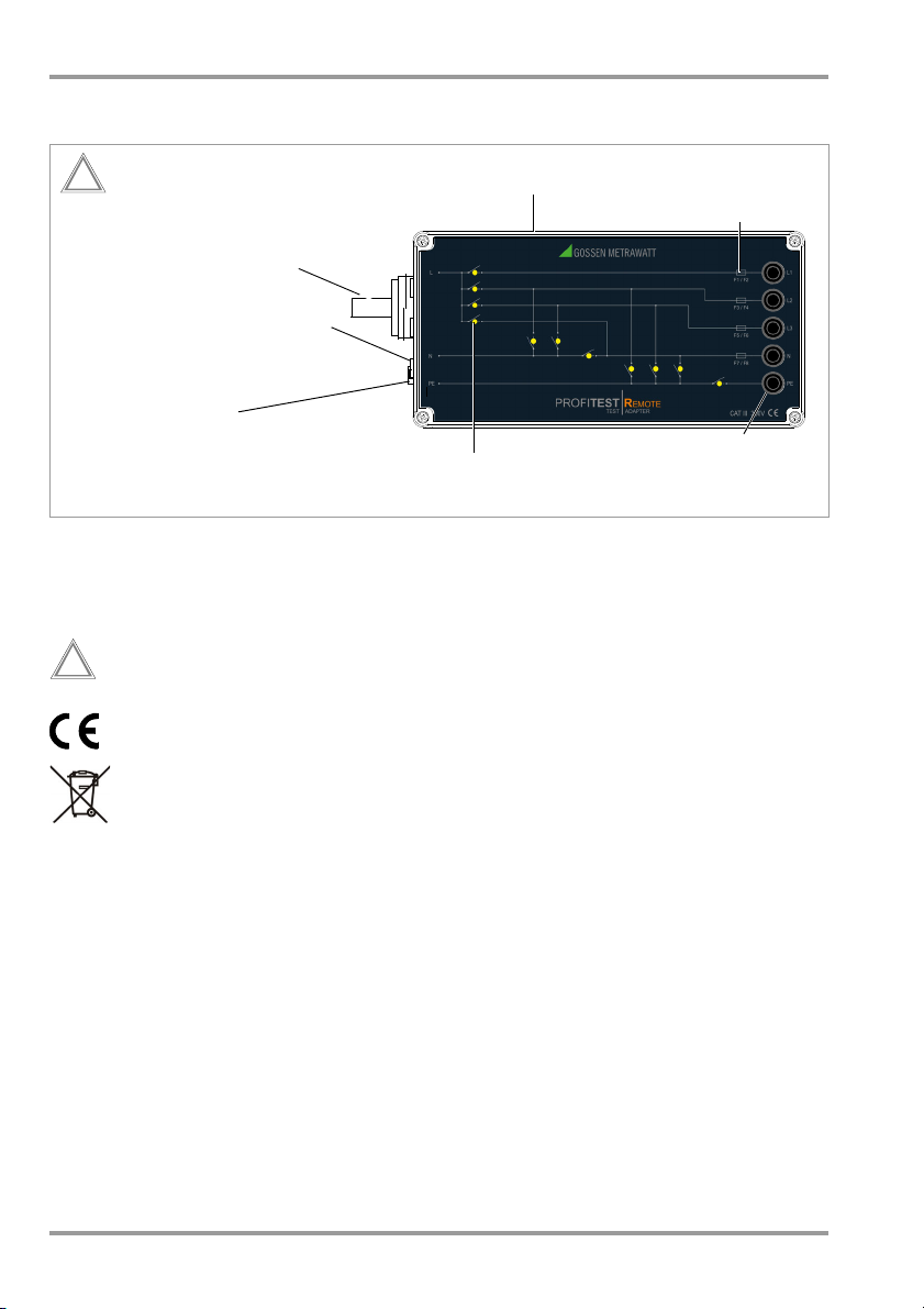
Allocation of fuses
Measurement Input
Conductor LEDs indicate
conductor continuity
Location of Fuses
- PRO-SCHUKO plug insert
for PROFITEST MTECH+
RS 232 port
!
Max. 500 V
for Mains Connection
and MXTRA
- Three 4 mm safety sockets
for PROFITEST PRIME
for test adapter controller
Five 4 mm safety
sockets for mains/system
connection
and power supply
!
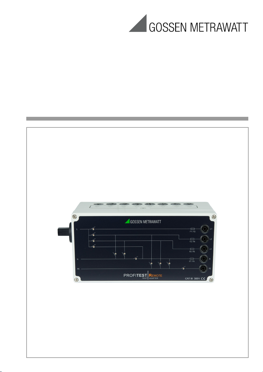
PROFITESTREMOTE Connections Overview – Symbols – Scope of Delivery
Connections Overview
Meanings of Symbols on the Instrument
300 V CAT III
2 GMC-I Messtechnik GmbH
Maximum permissible voltage and
measuring category between connections and ground
Warning concerning a point of
danger (attention: observe documentation!)
Indicates European Conformity
This device may not be disposed
of with household trash.
Further information regarding the
WEEE mark can be accessed on
the Internet at www.gossenmetrawatt.com by entering the
search term “WEEE”.
Scope of Delivery
1 Test adapter (M514R)
1 RS 232 interface cable, type Z3241
1 Set of operating instructions
Page 3

PROFITESTREMOTE Table of Contents – Safety Precautions
Table of Contents Page
1 Safety Precautions .....................................3
2 Applications ...............................................5
3 Initial Startup .............................................6
3.1 Testing the LEDs ..........................................6
3.2 Connecting the Test Instrument to the Test
Adapter .......................................................6
3.3 Connection to the System or the Mains .........6
3.4 Key and Significance of the LEDs ..................7
4 Measurements ...........................................8
ZL-PE
) ................ 10
ISO) ..........8
4.1 Measuring Insulation Resistance (R
4.1.1 Measuring Insulation Resistance with the
PROFITEST MTECH+ or MXTRA ...........................8
4.1.2 Measuring Insulation Resistance with the
PROFITEST PRIME ..............................................9
4.2
Measuring Loop Impedance (
4.2.1 Measuring Loop Resistance with the
PROFITEST MTECH+ or MXTRA .........................10
4.2.2
Measuring Loop Impedance with the
PROFITEST PRIME
............................................... 10
4.3 Measuring Line Impedance (ZL-N) ...............11
4.3.1 Measuring Line Impedance with the
PROFITEST MTECH+ and MXTRA ......................11
4.3.2 Measuring Line Impedance with the
PROFITEST PRIME ............................................12
4.4 Error Messages at the Test Instrument ........13
5 Characteristic Values ...............................14
6 Maintenance ............................................15
6.1 Housing Maintenance .................................15
6.2 Technical Safety Inspections,
Testing per DGUV Regulation 3 ...................15
6.2.1
Testing Protective Conductor Resistance .......................15
6.2.2 Testing Insulation Resistance ..............................15
6.3 Fuse Replacement .....................................15
6.4 Return and Environmentally Sound Disposal .16
7 Repair and Replacement Parts Service
Calibration Center and Rental Instrument
Service .....................................................16
8 Product Support .......................................16
1 Safety Precautions
The test adapter has been manufactured
and tested in accordance with the following
safety regulations:
I
EC/EN 61010-1/VDE 0411-1,
DIN EN 61326-1/VDE 0843-20-1
Safety of the operator, as well as that of the
test adapter, is only assured when it’s used
for its intended purpose.
Use for intended purpose stipulates application for loop and line impedance measurement Z
L-PE and ZL-N as well as insulation
resistance measurement R
combination with the
– PROFITEST MTECH+, as of FW V03.04.00
– PROFITEST MXTRA, as of FW V03.04.00
– PROFITEST PRIME, as of FW V03.05.00
test instruments. Any other application (e.g.
voltage measurement or use in combination
with other test instruments) are not permissible.
Read the operating instructions carefully and
completely before placing your test instrument
into service. Follow all instructions contained
therein. Make sure that the operating instructions
are available to all users of the device.
Read the operating instructions for the respective
test instrument as well, in particular the sections
concerning the measurement of insulation, loop
and internal line resistance.
Tests may only be performed by a qualified electrician, or under the supervision and direction of a
qualified electrician. The user must be instructed
by a qualified electrician concerning performance
and evaluation of the test (see also training seminars listed at www.gossenmetrawatt.com).
ISO exclusively in
GMC-I Messtechnik GmbH 3
Page 4

PROFITESTREMOTE Safety Precautions
Observe the following safety precautions:
• The device may only be connected to electrical systems with a maximum of 230/
400 V which comply with applicable safety
regulations
(e.g. IEC 60346, VDE 0100) and are protected with a fuse or circuit breaker with a
maximum rating of 16 A.
• The test adapter may only be used for tests
described in the section entitled “Applications”.
• When using a test probe with coil cord:
Grip the tip of the test probe firmly, for
example if it has been inserted into a jack
socket. Tensioning at the coil cord may
otherwise cause the test probe to snap
back resulting in possible injury.
• Insulation resistance can only be measured at voltage-free systems.
• Do not touch the test probes during
measurement!
Fuse Replacement
All fuses for the test adapter’s neutral and
phase conductors are accessible from the
outside (see section 6.3). The fuses may
only be replaced when the instrument is voltage-free, i.e. the instrument must be disconnected from mains supply power and may
not be connected to a measuring circuit. The
fuse type must comply with the specifications in the technical data or the labeling on
the instrument (see section 5).
Opening the Device / Repairs
The test adapter may only be opened by
authorized, trained personnel in order to
ensure flawless operation and to assure that
the guarantee is not rendered null and void.
Even original replacement parts may only be
installed by authorized, trained personnel.
If it can be ascertained that the test adapter
has been opened by unauthorized personnel, no guarantee claims can be honored by
the manufacturer with regard to personal
safety, measuring accuracy, compliance
with applicable safety measures or any consequential damages.
The test adapter may not be used:
• If external damage is apparent, for example if parts which conduct dangerous
touch voltage are freely accessible, and
in the event of defective LEDs
•
With damaged connection and/or measurement cables, e.g. interrupted insulation or
kinked cable
• If it no longer functions flawlessly
• After extraordinary stressing due to transport
In such cases, the test adapter must be
removed from operation and secured against
unintentional use.
4 GMC-I Messtechnik GmbH
Page 5
Note!
Note!
PROFITESTREMOTE Applications
2 Applications
Use of the test adapter eliminates bothersome replugging, and thus reversing of the
phases as well during measurement of RISO,
Z
L-PE and ZL-N.
The following measurements are supported:
L1-PE, L2-PE, L3-PE,
N-PE, L+N-PE,
L1-N, L2-N, L3-N,
L1-L2, L1-L3, L2-L3
The following test instruments are suitable
for use with the test adapter:
– PROFITEST MTECH+, as of FW V03.04.00
– PROFITEST MXTRA, as of FW V03.04.00
– PROFITEST PRIME, as of FW V03.05.00
Indication of Conductor Connections
The LEDs indicate conductor continuity
between the connected system and the test
instrument’s input:
– Red LED: Switch closed,
– Green LED: Switch open, no connection
The line circuit-breaker is opened and
closed via the test adapter controller at the
respective test instrument.
conductor continuity
Measuring Loop and Line Impedance Z
L-PE and
ZL-N
Loop impedance is the sum of all resistances within the distribution network and
the conductors in the branch circuit.
In order to be able to determine the effectiveness of residual current devices, loop
impedance Z
L-PE must be ascertained
between the phase conductor and the protective conductor. The same measuring procedure is used for line impedance Z
also the case for loop impedance Z
L-N as is
L-PE.
However, the current loop is completed via
neutral conductor N, rather than protective
conductor PE as is the case with loop
impedance measurement.
Observe the corresponding chapters in the
operating instructions of your test instrument
concerning correct measurement procedures.
Thanks to 4-wire measurement,
there’s no need to determine the test
adapter’s offset value.
Measuring Insulation Resistance
RISO in Electri-
cal Systems
In order to be able to detect faults in electrical systems which are caused by defective
insulation, insulation resistance must be
measured between each active conductor
and the protective earth conductor.
Observe the corresponding chapters in the
operating instructions of your test instrument
concerning correct measurement procedures.
Thanks to 4-wire measurement,
there’s no need to determine the test
adapter’s offset value.
GMC-I Messtechnik GmbH 5
Page 6

PROFITESTREMOTE Initial Start-Up
3 Initial Startup
3.1 Testing the LEDs
Before performing any measurements, the
LEDs should be tested for correct functioning. The test adapter has to be connected to
the test instrument via the serial port to this
end. Use the serial interface cable for this
purpose (included).
After switching the test instrument on, the
LEDs must light up green in all switch positions except for R
3.2 Connecting the Test Instrument to the Test Adapter
Connecting the Measurement Inputs
The respective test instrument is always
connected to the test adapter via 3 poles
using the PRO-SCHUKO plug insert or via
safety sockets L, N and PE.
PROFITEST MTECH+: test plug
PROFITEST MXTRA: test plug
PROFITEST PRIME: probes 1(L), 2(N), 3(PE)
This also applies in the case of 2-pole measurements, because the corresponding
probes are controlled from the test instrument via the test adapter controller – the
measurement cables or probes no longer
have to be manually replugged.
Data Interface Connection
The test adapter must also be connected to
the test instrument via the serial port in order
to control the line circuit-breaker, for the purpose of indication by means of the conductor LEDs and for power supply. Use the
serial interface cable to this end (included).
ISO, ZL-P and ZL-N.
3.3 Connection to the System or the Mains
The test adapter must be connected to the
system for all tests (see connections overview on page 2). The following adapter
cables are available for this purpose:
Description Type Article No.
Adapter cable with 5pole 16 A CEE plug
and
4 mm safety plugs
(L1, L2, L3, N, PE),
CAT III 300 V,
cable length: 4.8 m
Adapter cable with 5pole 32 A CEE plug
4 mm safety plugs
and
(L1, L2, L3, N, PE),
CAT III 300 V,
cable length: 4.8 m
Adapter cable with 5pole 63 A CEE plug
and
4 mm safety plugs
(L1, L2, L3, N, PE),
CAT III 300 V,
cable length: 4.8 m
➭ Disconnect the system from all sources
of voltage and secure against restart.
➭ Check the measuring points for absence
of voltage before connecting them to the
test adapter.
➭ Using the appropriate adapter cable,
connect the test adapter to the system
via connector sockets L1, L2, L3, N and
PE:
Refer to the characteristic values on
page 14 for nominal mains values.
ConnectingCable-16 Z570B
ConnectingCable-32 Z570C
ConnectingCable-63 Z570D
6 GMC-I Messtechnik GmbH
Page 7

LED 1
LED 2
LED 3
LED 4
LED 5
LED 7
LED 11
LED 9
LED 10
LED 6
LED 8
PROFITESTREMOTE Initial Start-Up
3.4 Key and Significance of the LEDs
Significance of the LEDs
LED lights up red:
LED lights up green: Switch open
Switch closed
LED Test
The LEDs must light up green in all switch
positions except for R
ISO, ZL-P and ZL-N.
Repeat the LED test after each test run.
GMC-I Messtechnik GmbH 7
Page 8

Note!
Attention!
!
Attention!
!
Attention!
!
Attention!
!
PROFITESTREMOTE Measurements
4 Measurements
The test adapter can remain connected to
the system or the mains during the course of
all measurements, assuming absence of
voltage during the insulation resistance measurement.
The fuses have to be checked before
each measurement. Blown fuses
must be replaced with new ones (see
“Fuse Replacement” on page 15).
4.1 Measuring Insulation Resistance
(R
ISO)
Single-Phase Mains Connection
The phase must be connected to L1
for single-phase mains connection.
➭ Make sure that the system remains volt-
age-free for the entire duration of the
measurement.
Insulation resistance can only be
measured at voltage-free systems.
The N and PE conductors must be
disconnected at all times. Consuming devices should not be connected.
Performing Measurement
Insulation test voltage may not exceed 500 V.
➭ Perform the measurement as described
in the operating instructions for the respective test instrument:
PROFITEST MTECH+: sections 5.8 and 11
PROFITEST MXTRA: sections 5.8 and 11
Overview of Connected Conductors
The red illuminated LEDs in the connections
overview indicate the respectively connected
(closed) conductors.
Continuity, MTECH/MXTRA R
Test
R
INS
ISO
LED Displays (red)
Sequence
01/11 N-PE LED4 + LED11
02/11 L1-PE LED1 + LED11
03/11 L2-PE LED2 + LED11
04/11 L3-PE LED3 + LED11
05/11 L+N-PE
06/11 L1-N LED1 + LED10
07/11 L2-N LED2 + LED10
08/11 L3-N LED3 + LED10
09/11 L1-L2 LED1 + LED8
10/11 L2-L3 LED2 + LED9
11/11 L1-L3 LED1 + LED9
LED1 + LED2 +
LED3 + LED4 +
LED11
4.1.1 Measuring Insulation Resistance with
the
PROFITEST MTECH+ or MXTRA
Preparing for Measurement
➭ Connect the test instrument’s test plug
to the PRO-SCHUKO plug insert.
➭ Disconnect the system from all sources
of voltage before connecting the measuring points to the test adapter.
➭ Connect the system to sockets L1, L2,
L3, N and PE.
8 GMC-I Messtechnik GmbH
Page 9

Attention!
!
PROFITESTREMOTE Measurements
4.1.2 Measuring Insulation Resistance with the PROFITEST PRIME
Preparing for Measurement
➭ Using the corresponding test probes,
connect the test instrument to the L, N
and PE sockets at the test adapter.
➭ Disconnect the system from all sources
of voltage before connecting the measuring points to the test adapter.
➭ Connect the system to sockets L1, L2,
L3, N and PE.
Performing the Measurement
Insulation test voltage may not exceed 500 V.
➭ Perform the measurement as described
in the operating instructions for the test
instrument:
PROFITEST PRIME: sections 8.6 and 11
➭ The following measuring functions are
available for the measurement of insulation resistance: insulation measurement
with constant voltage and insulation measurement with rising test voltage
.
Overview of Connected Conductors
The red illuminated LEDs in the connections
overview indicate the respectively connected
conductors.
Continuity, PRIME
Test
RISO
R
INS
LED Displays (red)
Sequence
01/11 N-PE LED4 + LED11
02/11 L1-PE LED1 + LED11
03/11 L2-PE LED2 + LED11
04/11 L3-PE LED3 + LED11
05/11 L+N-PE
06/11 L1-N LED1 + LED10
07/11 L2-N LED2 + LED10
08/11 L3-N LED3 + LED10
09/11 L1-L2 LED1 + LED8
10/11 L2-L3 LED2 + LED9
11/11 L1-L3 LED1 + LED9
LED1 + LED2 +
LED3 + LED4 +
LED11
GMC-I Messtechnik GmbH 9
Page 10

Attention!
!
Attention!
!
Attention!
!
Note!
PROFITESTREMOTE Measurements
4.2 Measuring Loop Impedance (ZL-PE)
Single-Phase Mains Connection
The phase must be connected to L1
for single-phase mains connection.
4.2.1 Measuring Loop Resistance with the PROFITEST MTECH+ or MXTRA
Preparing for Measurement
➭ Connect the test instrument’s test plug
to the PRO-SCHUKO plug insert.
➭ Disconnect the system from all sources
of voltage before connecting the measuring points to the test adapter.
➭ Connect the system to sockets L1, L2,
L3, N and PE.
➭ Switch the system on.
Performing the Measurement
Insulation test voltage may not exceed 500 V.
➭ Perform the measurement as described
in the operating instructions for the respective test instrument:
PROFITEST MTECH+: sections 5.8 and 8
PROFITEST MXTRA: sections 5.8 and 8
Overview of Connected Conductors
The red illuminated LEDs in the connections
overview indicate the respectively connected
conductors.
Continuity, ZL-
Test
PE
Z
L-P E
LED Display (red)
Sequence
01/3 L1-PE LED1 + LED11
02/3 L2-PE LED2 + LED11
03/3 L3-PE LED3 + LED11
4.2.2 Measuring Loop Impedance with the PROFITEST PRIME
Preparing for Measurement
➭ Using the corresponding test probes,
connect the test instrument to the L, N
and PE sockets at the test adapter.
➭ Disconnect the system from all sources
of voltage before connecting the measuring points to the test adapter.
➭ Connect the system to sockets L1, L2,
L3, N and PE.
➭ Switch the system on.
Performing the Measurement
Insulation test voltage may not exceed 500 V.
➭ Perform the measurement as described
in the operating instructions for the test
instrument:
PROFITEST PRIME: sections 8.6 and 13
➭ Loop impedance is measured using the
Z
LOOP AC/DC measurement variant.
Measurement with the following measurement variants is not possible with
the PROFITEST PRIME:
– Z
LOOP DC+
LOOP
– Z
– ZLOOP
10 GMC-I Messtechnik GmbH
Page 11

Attention!
!
Attention!
!
PROFITESTREMOTE Measurements
Overview of Connected Conductors
The red illuminated LEDs in the connections
overview indicate the respectively connected
conductors.
Continuity,
Test
ZLOOP AC/DC
Z
AC/DC LED Display (red)
loop
Sequence
01/9 L1-PE LED1 + LED11
02/9 L2-PE LED2 + LED11
03/9 L3-PE LED3 + LED11
04/9 L1-N LED1 + LED10
05/9 L2-N LED2 + LED10
06/9 L3-N LED3 + LED10
07/9 L1-L2 LED1 + LED8
08/9 L2-L3 LED2 + LED9
09/9 L1-L3 LED1 + LED9
4.3 Measuring Line Impedance (ZL-N)
Single-Phase Mains Connection
The phase must be connected to L1
for single-phase mains connection.
4.3.1 Measuring Line Impedance with the PROFITEST MTECH+ and MXTRA
Preparing for Measurement
➭ Connect the test instrument’s test plug
to the PRO-SCHUKO plug insert.
➭ Disconnect the system from all sources
of voltage before connecting the measuring points to the test adapter.
➭ Connect the system to sockets L1, L2,
L3, N and PE.
➭ Switch the system on.
Performing the Measurement
Insulation test voltage may not exceed 500 V.
➭ Perform the measurement as described
in the operating instructions for the respective test instrument:
PROFITEST MTECH+: sections 5.8 and 8
PROFITEST MXTRA: sections 5.8 and 8
GMC-I Messtechnik GmbH 11
Page 12

Attention!
!
PROFITESTREMOTE Measurements
Overview of Connected Conductors
The red illuminated LEDs in the connections
overview indicate the respectively connected
conductors.
Continuity, Z
Test
L-N
R
INS
LED Displays (red)
Sequence
01/6 L1-N LED1 + LED7
02/6 L2-N LED2 + LED7
03/6 L3-N LED3 + LED7
04/6 L1-L2 LED1 + LED5
05/6 L2-L3 LED2 + LED6
06/6 L1-L3 LED1 + LED6
4.3.2 Measuring Line Impedance with the PROFITEST PRIME
Preparing for Measurement
➭ Using the corresponding test probes,
connect the test instrument to the L, N
and PE sockets at the test adapter.
➭ Disconnect the system from all sources
of voltage before connecting the measuring points to the test adapter.
➭ Connect the system to sockets L1, L2,
L3, N and PE.
Performing the Measurement
Overview of Connected Conductors
The red illuminated LEDs in the connections
overview indicate the respectively connected
conductors.
Continuity,
Test
ZLOOP AC/DC
Z
AC/DC
loop
LED Displays (red)
Sequence
01/9 L1-PE LED1 + LED11
02/9 L2-PE LED2 + LED11
03/9 L3-PE LED3 + LED11
04/9 L1-N LED1 + LED10
05/9 L2-N LED2 + LED10
06/9 L3-N LED3 + LED10
07/9 L1-L2 LED1 + LED8
08/9 L2-L3 LED2 + LED9
09/9 L1-L3 LED1 + LED9
Insulation test voltage may not exceed 500 V.
➭ Perform the measurement as described
in the operating instructions for the test
instrument:
PROFITEST PRIME: sections 8.6 and 13
➭
Line impedance is measured using the
LOOP
AC/DC measurement variant.
Z
➭ Switch the system on.
12 GMC-I Messtechnik GmbH
Page 13

PROFITESTREMOTE Measurements
4.4 Error Messages at the Test Instrument
LCD Pictogram Test
Plug
Measuring
Adapter
XX R
XX All
XX R
Position of the
Function Switch
ISO
ISO
Function / Meaning
Check mains connections for
absence of voltage. If voltage is
present, it results in short-circuiting between L and N and the
device’s fuses are blown.
Remedy: Assure absence of voltage before switching through!
No interface connection between
the test instrument and the test
adapter.
Remedy: Check the interface
connection and establish connection if necessary. Use the
serial interface cable for this purpose (included).
Contact error or defective fuse.
Remedy: Check the test plug for
proper fit with the test adapter or
replace fuse in the test instrument
or test adapter.
GMC-I Messtechnik GmbH 13
Page 14

PROFITESTREMOTE Characteristic Values
5 Characteristic Values
Measurement input PRO-SCHUKO plug
insert for PROFITEST
MTECH+ and MXTRA,
three 4 mm safety
sockets
PROFITEST PRIME
Mains connection Five 4 mm safety
sockets,
(adapter cable for
CEE 16A, CEE 32A
and CEE 63A available as accessory)
Ambient Conditions
Operating temperature
+5 ... + 45 C
Storage temperature -20 ... + 60 C
Relative humidity
Max. 75%, no condensation allowed
Elevation Max. 2000 m
Power Supply
Auxiliary voltage 5 V via RS 232 port
Current consumption 60 mA (all relays
dropped out)
240 mA (2 relays
picked up)
600 mA (all relays
picked up)
Power consu mption 3 W
Electrical Safety
Measuring category 300 V CAT III
Pollution degree 2
Protection class II per IEC 61010-1/
EN 61010-1/
VDE 0411-1
Fuse links F1 to F8:
8xF 8.0A H/500V
Test voltage Insulation test voltage
may not exceed
500 V.
Operating conditions Continuous operation
Electromagnetic Compatibility (EMC)
Interference emission EN 61326-1:2013,
class B
Interference immunity EN 61 326-1:2013
EN 61326-2-1:2013
Mechanical Design
Protection Housing: IP 40 per
DIN VDE 0470, part
1 / EN 60 529
Table Excerpt Regarding Significance of
IP Codes
4
Protection
Against For-
eign Object In-
gress
1.0 mm dia.
IP XY
(2nd digit Y)
Protection Against
Water Ingress
0 Not protected
Housing (W x H x D):
IP XY
(1st digit X)
Dimensions
approx. 27.5 x 10.5 x
12 cm
(with
PRO-SCHUKO
plug insert
)
Weight Approx. 1.1 kg
(test adapter without
interface cable)
Data Interface
Transmission
parameters 9600 baud,
1 stop bit, no parity
Transmission format All commands are
transmitted as ASCII
character strings.
14 GMC-I Messtechnik GmbH
Page 15

Fuse Holders
PROFITESTREMOTE Maintenance
6 Maintenance
6.1 Housing Maintenance
No special maintenance is required. Keep
outside surfaces clean and dry. Use a
slightly dampened cloth for cleaning. Avoid
the use of solvents, cleansers and abrasives.
6.2 Technical Safety Inspections, Testing per DGUV Regulation 3
Subject your test adapter to technical safety
inspections at regular intervals.
The test adapter is designed in accordance
with IEC 61010 and VDE 0413-16 as a protection category I and II test instrument.
Testing of protective conductor and insulation resistance is described in the following
subsections.
6.2.1 Testing Protective Conductor Resistance
Testing the 3-Phase Connection
Protected conduct or resistance values of
R
PE <2 are permissible. This is due to the
design of the test adapter.
Connecting/Contacting the Test Adapter,
3-Phase (400 V)
Protective conductor resistance is tested
between the PE safety contact at the mains
connection sockets and the parallel connected 4 mm safety socket at the PE measurement input.
6.2.2 Testing Insulation Resistance
Testing is conducted respectively between
short-circuited contacts L
the mains connection safety sockets and
between L-N and PE for the measurement
inputs.
The usual limit values apply.
-N and PE for
123
6.3 Fuse Replacement
All eight fuses for neutral (F7/F8) and phase
conductors (F1 to F6) are accessible from
the outside.
The fuses may only be replaced when the
device is voltage-free, i.e. the device must
be disconnected from mains supply power
and may not be connected to a measuring
circuit. The respective fuse type must comply with the specifications in the technical
data or the labeling on the device.
➭ Unscrew the appropriate fuse holder
with the help of a suitable screwdriver.
➭ Remove the blown fuse from the holder.
➭ Insert the new fuse into the holder.
➭ Reinsert the fuse holder and screw it
tight.
GMC-I Messtechnik GmbH 15
Page 16

PROFITESTREMOTE Addresses
6.4 Return and Environmentally Sound Disposal
The device is a category 9 product (monitoring and control instrument) in accordance
with ElektroG (German electrical and electronic device law).
This device is subject to the RoHS directive.
We also make reference to the fact that in
this regard, the current status can be found
on the Internet at www.gossenmetrawatt.com
by entering the search term WEEE.
We identify our electrical and electronic devices in accordance with
WEEE 2012/19/EU and ElektroG
using the symbol shown at the
right per DIN EN 50419. These devices may
not be disposed of with the trash.
Please contact our service department
regarding the return of old devices (see
address below).
7 Repair and Replacement Parts
Service Calibration Center and
Rental Instrument Service
If required please contact:
GMC-I Service GmbH
Service Center
Beuthener Str. 41
90471 Nürnberg, Germany
Phone: +49-911-817718-0
Fax: +49-911-817718-253
e-mail service@gossenmetrawatt.com
www.gmci-service.com
8 Product Support
If required please contact:
GMC-I Messtechnik GmbH
Product Support Hotline
Phone: +49-900-1-8602-00
Fax: +49 911 8602-709
e-mail:
support@gossenmetrawatt.com
This address is only valid in Germany. Please
contact our representatives or subsidiaries
for service in other countries.
Prepared in Germany • Subject to change without notice • PDF version available on the Internet
GMC-I Messtechnik GmbH
Südwestpark 15
90449 Nürnberg •
Germany
Phone: +49 911 8602-111
Fax: +49 911 8602-777
e-mail: info@gossenmetrawatt.com
www.gossenmetrawatt.com
 Loading...