

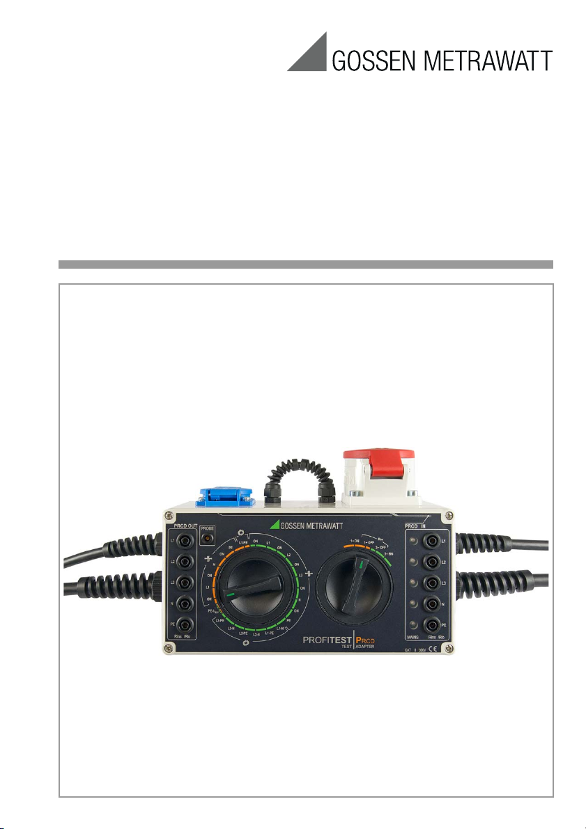
Operating Instructions
PROFITEST⏐PRCD
Adapter for Standards Compliant Testing of PRCDs
by Simulating Faults
Important
Read carefully before use!
Keep on file for future reference!
Please observe the manufacturer‘s details
on the devices under test!
3-349-797-15
5/2.18
8
7
6
4
1
2
10
3
9
Mains Connection
To P R C D O u t le t
To PR C D In l e t (PRCD IN)
5
11
(PRCD OUT)
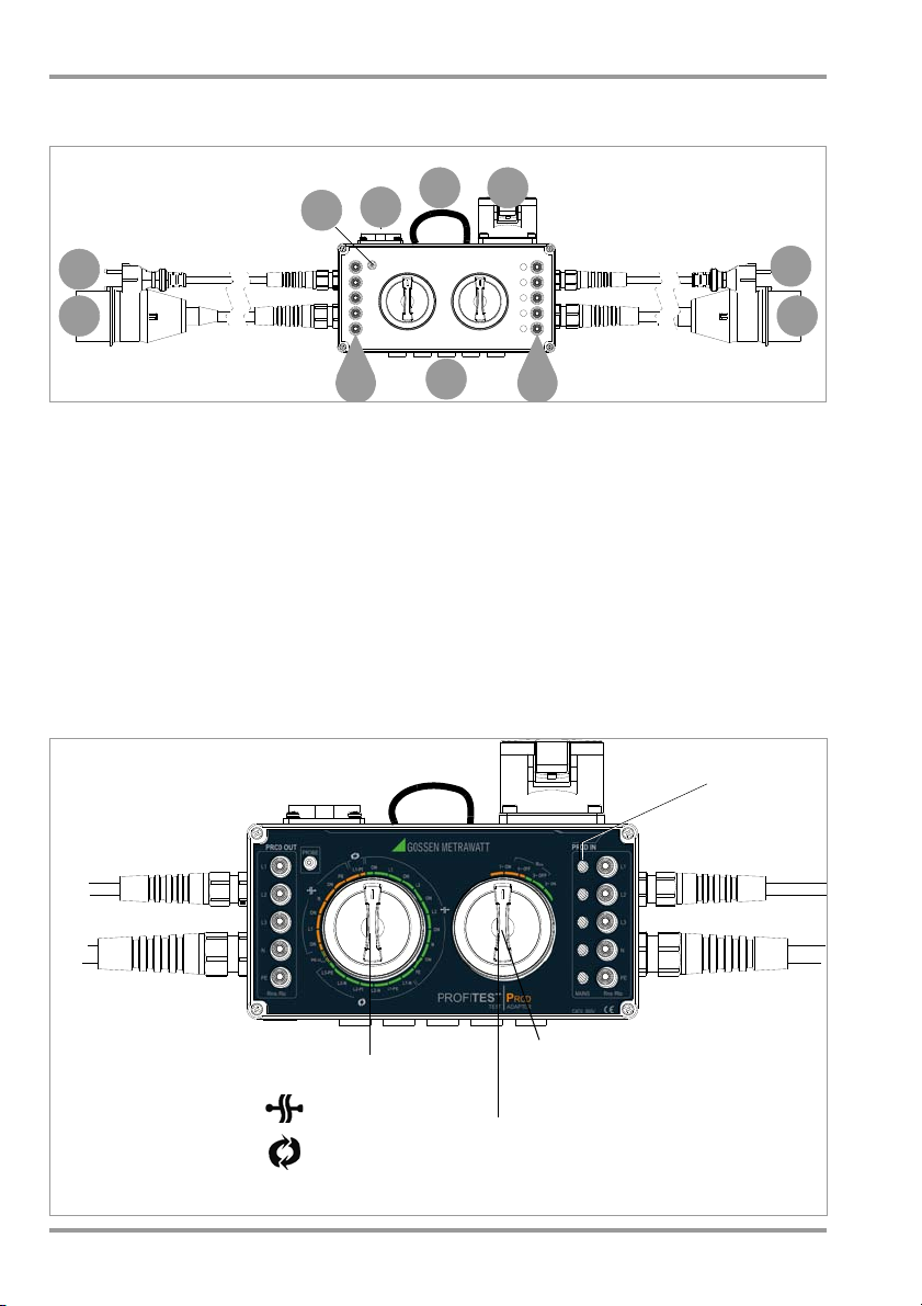
Fault Selection
Mains disconnect, 1~OFF/3~OFF
– For RISO measurement
Mains power on, 1~ON/3~ON
– For fault simulation
– For RLO measurement
Phase LEDs
Phase Interrupt
Reversed Wires
Orange positions: testing at single-phase PRCDs
Green positions: testing at 3-phase PRCDs
Mains
– For tripping test with I
Nom
and measurement of time to trip
Connection
PROFITEST⏐PRCD Operating and Connections Overview
Connections Overview
1 Coupling plug to the outlet of a
3-phase PRCD
2 Earthing contact plug to the outlet of a
single-phase PRCD
3 Probe socket for contacting the on/off
switch on the PRCD
4 Earthing contact socket to the inlet of a
single-phase PRCD
5 Loop for measuring protective conductor
current with a current clamp transformer
6 CEE socket to the inlet of a 3-phase
PRCD
Instrument Overview
7 Mains power cable with earthing contact plug
8 3-phase mains power cable with
CEE outlet (1P+N+PE 16 A-6h)
9 PRCD inlet sockets connected in parallel
to sockets 4 and 6 – for connecting the
PROFITEST MXTRA during protective conductor and insulation measurements
10 PRCD outlet sockets connected in paral-
lel to plugs 1 and 2 for connecting the
PROFITEST MXTRA during protective conductor and insulation measurements
11 Five replaceable fuses
2 GMC-I Messtechnik GmbH
!
PROFITEST⏐PRCD Symbols – Scope of Delivery – Table of Contents
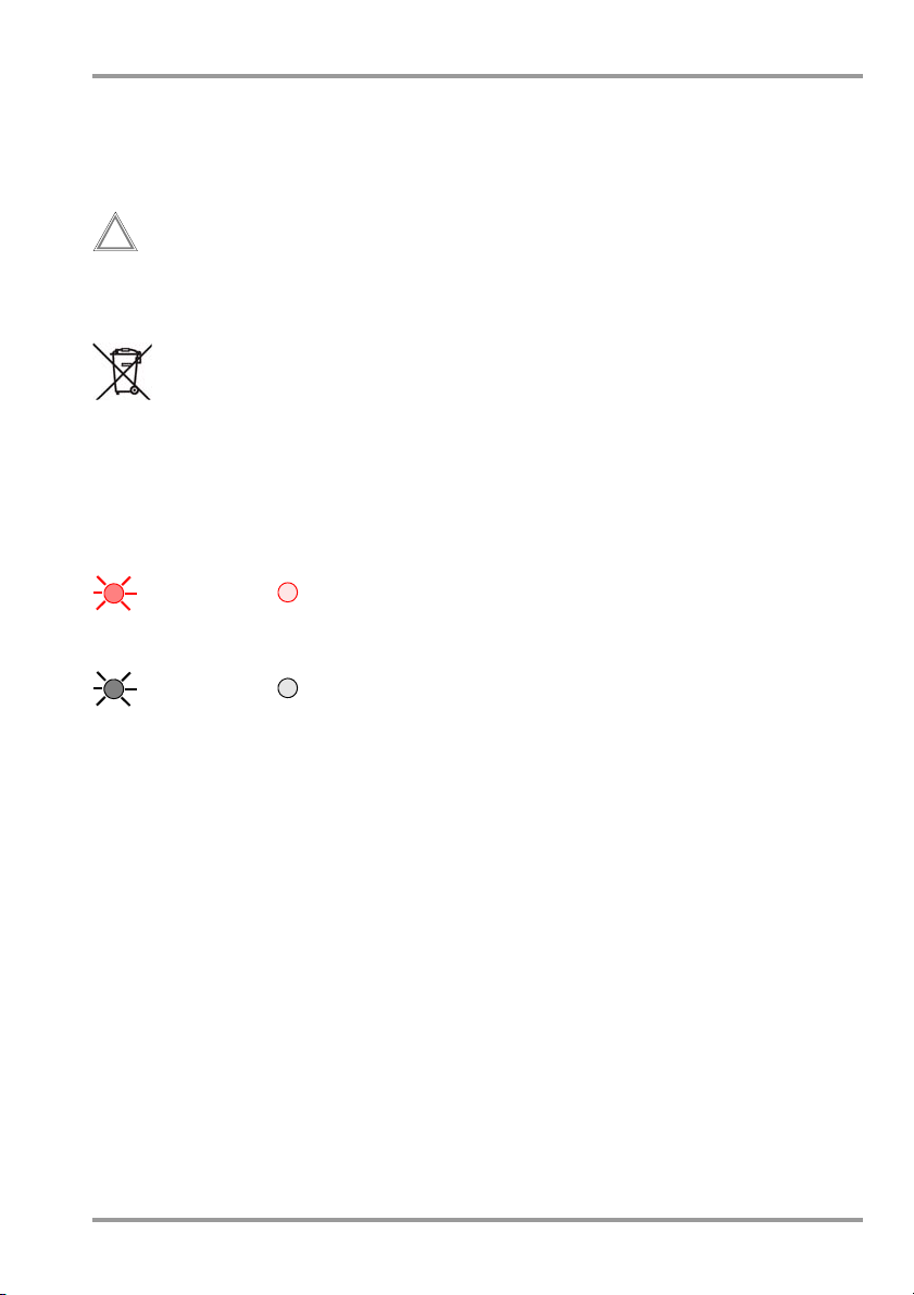
Meanings of Symbols on the Instrument
300 V CAT II
Maximum permissible voltage and
measuring category between connections and ground
Warning concerning a point of
danger
(attention:
observe documentation!)
EC mark of conformity
This device may not be disposed
of with the trash.
Further information regarding the
WEEE mark can be accessed on
the Internet at www.gossenmetrawatt.com by entering the
search term “WEEE”.
Meanings of Symbols in the Operating Instructions
LED L1, L2, L3, N or PE at test adapter
LED on LED off
PRCD LED at the device under test
LED on LED off
Scope of Delivery
1 Test adapter
1 Probe cable with plug-in test probe
1 Set of operating instructions
Table of Contents Page
1 Safety Precautions .................................... 4
2 Applications .............................................. 5
3 Initial Start-Up ........................................... 6
3.1 Testing the LEDs ......................................... 6
3.2 Mains Connection ....................................... 6
3.3 Connecting the PRCD .................................. 6
4 Measurements with the
PROFITEST MXTRA .................................... 6
Measuring Protective Conductor Resistance (Rlo) ....... 7
4.1
4.2
Measuring Insulation Resistance (Riso) ............. 7
4.3
Tripping Test with Nominal Residual Current and
Measurement of Time to Trip ............................... 8
4.4 Varistor Test (PRCD-K) ................................. 8
5 Protective Conductor Current Measurement 9
6 Fault Simulation ...................................... 10
6.1 PRCD-S (single-phase) ............................. 10
6.1.1 Simulated Interruption ....................................... 10
6.1.2 Simulated Wire Reversal .................................... 10
6.1.3 Simulation of PE to Phase – PE-UEXT ................. 10
6.1.4 Contacting the “ON” Key at the PRCD with the Probe 11
6.2 PRCD-K (single-phase) ............................. 11
6.2.1 Simulated Interruption ....................................... 11
6.3 PRCD-S (3-phase) .................................... 12
6.3.1 Simulated Interruption ....................................... 12
6.3.2 Simulated Wire Reversal .................................... 13
6.3.3 Simulation of PE to Phase ................................... 13
7 Characteristic Values .............................. 14
8 Maintenance ........................................... 14
8.1 Housing Maintenance ................................ 14
8.2 Safety Checks............................................ 15
8.2.1
Testing of Protective Conductor Resistance RPE ............15
8.2.2 Testing of Insulation Resistance: ......................... 15
8.2.3 Contact Current Measurement ............................ 16
8.3 Fuse Replacement ..................................... 16
8.4 Return and Environmentally Sound Disposal 16
9
Repair and Replacement Parts Service, Calibration
Center and Rental Instrument Service .................16
10 Product Support ...................................... 16
GMC-I Messtechnik GmbH 3

PROFITEST⏐PRCD Safety Precautions
1 Safety Precautions
The test adapter has been manufactured
and tested in accordance with the following
safety regulations:
IEC/EN 61010-1 / VDE 0411-1, DIN VDE
0404, IEC/EN 61577 / VDE 0413-2,-4 /
DIN EN 61557-16 / VDE 0413-16 (draft)
Safety of the operator, as well as that of the
test adapter and the PRCD, is only assured
when it is used for its intended purpose.
Read the operating instructions carefully and
completely before placing your test instrument
into service. Follow all instructions contained
therein. Make sure that the operating instructions
are available to all users of the instrument.
Read the operating instructions for the PROFITEST
MXTRA as well, in particular the sections concerning the R
ments, as well as the tripping test.
Tests may only be performed by a qualified
electrician, or under the supervision and
direction of a qualified electrician. The user
must be instructed by a qualified electrician
concerning performance and evaluation of
the test.
Observe the following safety precautions:
• The instrument may only be connected
to electrical systems with a maximum of
230/400 V which comply with applicable
safety regulations (e.g. IEC 60346, VDE
0100) and are protected with a fuse or
circuit breaker with a maximum rating of
16 A.
• The test adapter may only be used for
testing PRCDs.
• No power consuming devices may be
connected to the earthing contact and
CEE sockets.
• The test adapter may not be used as an
extension cord.
• Measurements within electrical systems
are prohibited.
• Make certain that the measurement
cables are in flawless condition, e.g. no
damage to insulation, no cracks in
cables or plugs etc.
, R
and time-to-trip measure-
LO
ISO
• When using a test probe with coil cord
(PROFITEST MXTRA):
Grip the tip of the test probe firmly, for
example during insertion into a jack
socket. Tensioning at the coil cord may
otherwise cause the test probe to snap
back resulting in possible injury.
• Insulation resistance can only be measured at voltage-free objects.
• Do not touch the insulation measuring
instrument’s test probes (PROFITEST
MXTRA) during insulation resistance measurements!
• Please observe the manufacturer‘s
details on the devices under test!
Fuse Replacement
All fuses for neutral and phase conductors
are accessible from the outside (see section
8.3). The fuses may only be replaced when
the instrument is voltage-free, i.e. the instrument must be disconnected from mains
supply power and may not be connected to
a measuring circuit. The fuse type must
comply with the specifications in the technical data or the labeling on the instrument
(see section 7).
Opening the Instrument / Repairs
The test adapter may only be opened by
authorized, trained personnel in order to
ensure flawless operation and to assure that
the guarantee is not rendered null and void.
Even original replacement parts may only be
installed by authorized, trained personnel.
If it can be ascertained that the test adapter
has been opened by unauthorized personnel, no guarantee claims can be honored by
the manufacturer with regard to personal
safety, measuring accuracy, compliance
with applicable safety measures or any consequential damages.
4 GMC-I Messtechnik GmbH

Attention!
!
PROFITEST⏐PRCD Applications
The test adapter may not be used:
• If external damage is apparent, for example if parts which conduct dangerous
touch voltage are freely accessible,
if its LEDs are defective (voltage at the
PRCD IN would no longer be indicated in
this case)
• If the seal or sealing lacquer has been
removed as the result of repairs or
manipulation carried out by a non-authorized/certified service provider
• With damaged connection and/or measurement cables, e.g. interrupted insulation or kinked cable
• If it no longer functions flawlessly
• After extraordinary stressing due to transport
In such cases, the test adapter must be
removed from operation and secured
against unintentional use.
2 Applications
Testing of PRCDs with the Test Adapter by
Simulating Faults
The following faults can be simulated with
regard to mains supply power to the PRCD:
• Wire reversals
• Failure of individual conductors
(undervoltage detection)
• Interference voltage on the protective
conductor
a) by connecting the phase conductor
to the protective conductor
(PE-U
switch setting) or
EXT
b) by touching the “on” key of the
single-phase PRCDs with the probe
The evaluation of the PRCD’s reaction to
each respective fault is strictly visual:
• PRCD active or inactive
(indicator lamp on the PRCD)
• Fault indication by means of LEDs on the
test adapter
In any case, comply with the manufacturer’s recommendations concerning tests to be conducted in
accordance with DGUV Provision 3.
Testing of PRCDs with the Test Adapter by Simulating Faults and Measuring Protective Conductor
and Insulation Resistance, as well as Tripping
Current and Time to Trip, using the PROFITEST
MXTRA Test Instrument
The following functions are possible after
connecting the PROFITEST MXTRA test instrument to the test adapter:
• There are three preset test sequences:
Single-phase PRCDs:
– PRCD-S: 11 test steps
– PRCD-K: 4 test steps
3-phase PRCDs:
– PRCD-S: 18 test steps
• The test instrument runs through all test
steps semi-automatically:
Single-phase PRCDs: 10 test steps
3-phase PRCDs: 17 test steps
• Each test step is evaluated and
assessed by the user (go/no-go) for later
documentation.
• Measurement of the PRCD’s protective
conductor resistance using the test
instrument’s R
that the protective conductor measure-
function. Please note
LO
ment is a modified RLO measurement
with ramp sequence for PRCDs, which is
only available with the PROFITEST MXTRA
test instrument.
• Measurement of the PRCD’s insulation
resistance using the test instrument’s
R
function.
ISO
• Tripping test with nominal residual current using the test instrument’s I
function.
F
• Measurement of time to trip using the
test instrument’s I
function.
ΔN
• Varistor test for PRCD-K:
Measurement via ISO ramp
Measuring Protective Conductor Current
Protective conductor current or bias current
may result in premature tripping of PRCDs.
For this reason, the protective conductor is
led out of the housing as a loop between
surface mount sockets 4 and 6. This makes
it possible to measure any protective conductor current with the help of a current
clamp transformer.
GMC-I Messtechnik GmbH 5

Attention!
!
PROFITEST⏐PRCD Initial Start-Up
3 Initial Start-Up
See the connections overview on page 2 for
all connection variants.
3.1 Testing the LEDs
Before performing any measurements, the
LEDs should be tested for correct functioning.
Single-Phase Mains Connection
➭ Insert the earthing contact plug into the
earthing contact mains outlet, remove it,
rotate it 180° and insert it again.
When connected with correct polarity, the
PRCD IN L1 LED must light up, and when
rotated 180° the PRCD IN L1 and PRCD IN PE
LEDs must light up simultaneously.
3-Phase Mains Connection
➭ Insert the CEE plug into the CEE outlet.
The PRCD IN L1, L2 and L3 LEDs must light
up. If any of the phase conductors are connected to the neutral conductor, i.e. L1-N,
L2-N or L3-N, N lights up instead Lx. If any
of the phase conductors are connected to
protective earth, i.e. L1-PE, L2-PE or L3-PE,
PE lights up instead of Lx.
3.2 Mains Connection
The test adapter must be connected to the
mains for fault simulation, as well as for indication by means of the phase LEDs.
➭ Connect the test adapter to the mains
via the single or 3-phase mains power
cable. Refer to the characteristic values
on page 14 for nominal mains values.
3.3 Connecting the PRCD
The respective PRCD must be connected to
the test adapter for all tests.
Connecting a Single-Phase PRCD
➭ Insert the earthing contact inlet plug from
the PRCD into the earthing contact outlet (4) at the test adapter.
➭ Insert the earthing contact plug (2) from
the test adapter into the outlet coupling
socket at the PRCD.
Example of a Single-Phase PRCD
Connecting a 3-Phase PRCD
➭ Insert the CEE inlet plug from the PRCD
into the CEE outlet (6) at the test
adapter.
➭ Insert the CEE plug (1) from the test
adapter into the CEE outlet coupling
socket at the PRCD.
Single-Phase Mains Connection
For correct phase connection, the
earthing contact plug must inserted
into the mains outlet such that only
the PRCD IN L1 LED lights up.
The PRCD IN PE LED lights up as well
in the case of polarity reversal.
6 GMC-I Messtechnik GmbH
4 Measurements with the
PROFITEST MXTRA
In order to perform protective conductor measurements (Rlo) at
MXTRA
, the test adapter must remain connected
to the mains.
The test adapter can remain connected to the
mains for protective conductor measurements
conducted at PRCDs whose protective conductor is not switched, as well as for insulation measurements (Rins) with the
type S PRCDs
PROFITEST MXTRA
with the
PROFITEST

Attention!
!
PROFITEST⏐PRCD Measurement with the PROFITEST MXTRA
4.1 Measuring Protective Conductor Resistance (Rlo)
As opposed to the usual default setting for
low-resistance measurements, the device
under test does not have to be disconnected from all sources of voltage in this
case. Depending on the PRCD, the rotary
selector switches have to be set to the ON
and the 1~ ON or 3~ ON positions, in order to
be able to activate the PRCD and switch the
protective conductor through.
Example of a Single-Phase PRCD
➭ Activate the PRCD.
➭ Perform the measurement as described
in the operating instructions for the
PROFITEST MXTRA
(section 12.2 as of V10).
4.2 Measuring Insulation Resistance (Riso)
The right-hand rotary selector switch
must be set to the mains disconnect
position: 1~ OFF or 3~ OFF.
➭ In order to perform the insulation mea-
surement (Rins), connect the PROFITEST
MXTRA test instrument, via the measuring
adapter, to socket 9 for the cable at the
mains side and to socket 10 for the
cable at the test object’s outlet side.
Example, Single-Phase PRCD OUT Sockets
➭ Before performing protective conductor
measurements, execute an offset measurement to assure that the test
adapter’s connector contacts are not included in the measurement results.
➭ Insert the respective test plug into the
appropriate socket at the test adapter to
this end: 2 to 4 or 1 to 6.
➭ Start the offset measurement at the
PROFITEST MXTRA
➭ Connect the PRCD as described in sec-
tion 3.3.
➭ Connect the PROFITEST MXTRA test instru-
ment to sockets 9 and 10 via the 2-pole
measuring adapter.
GMC-I Messtechnik GmbH 7
.
➭ Connect the PRCD as described in sec-
tion 3.3.
➭ Single-phase PRCD: Connect the
PROFITEST MXTRA test instrument, via the
2-pole measuring adapter, to the PRCD IN
/ OUT L1, N and PE sockets, one after the
other.

Note!
PROFITEST⏐PRCD Measurement with the PROFITEST MXTRA
➭ Perform the measurement as described
in section 11 of the operating instructions for the PROFITEST MXTRA .
➭
3-phase PRCD:
MXTRA
suring adapter, to the
Connect the
PROFITEST
test instrument, via the 2-pole mea-
PRCD IN / OUT
L1, L2,
L3, N and PE sockets, one after the other.
4.3 Tripping Test with Nominal Residual Current and Measurement of Time to Trip
If you operate your test adapter at an
electrical system with a 30 mA breaker,
the mains RCCB may be tripped during
the tripping test (tripping current and
time to trip) instead of the PRCD. In this
case the
In order to prevent an upstream RCD (also
non-selevtive RCD) from being tripped and
to ensure that the actual tripping current
and/or the correct time-to-trip are determined, we recommend the following procedure:
➭ Connect the PROFITEST MXTRA test instru-
ment via the 2-pole measuring adapter
with pole (L1) to L1 (PRCD-OUT) and
with pole (PE) to N (PRCD-IN).
Observe the correct polarity between
earthing contact plug and PRCD!
➭ Refer to the operating instructions for the
PROFITEST MXTRA regarding performance
of the measurement
Type K PRCD, section 7.3.2
Type S PRCD, section 7.3.3
MAINS L1
LED goes out.
:
4.4 Varistor Test (PRCD-K)
During this measurement, the voltage is
ascertained at which the varistor becomes
conductive, thus checking the varistor for
correct functioning as well. Measurement
can be performed by means of an ISO ramp,
or with a fixed test voltage of 50 V.
As a prerequisite for this measurement, the
device under test must be switched on.
➭ Connect the PROFITEST MXTRA test instru-
ment to the PE IN and PE OUT sockets via
the 2-pole measuring adapter.
➭ Perform the measurement as described
in the operating instructions for the PROF-
ITEST MXTRA (section 11).
➭
The evaluation of the measured varistor resistance depends on the manufacturer’s
specifications (PRCD-K from Kopp: e.g. 12
to 22 V according to Kopp).
Note on Kopp Test Specification:
PRCD-K (Varistor in Protective Earth Circuit)
Test Sequence by Kopp:
1.) Connect operating voltage (e. g. 230 V/
50 Hz) and 24 V AC voltage source.
2.) Select resistance (R) depending on the
residual current of the PRCD-K:
For PRCD-K
with In = 30 mA → R = 220 Ω/1 W.
For PRCD-K
with In = 10 mA → R = 620 Ω/0.5 W.
3.) Switch on PRCD-K by pressing the ON
button.
4.) Press key <T>
circuit is functioning properly.
→ device must trip → PE
The shutdown test of the PRCD-K stipulated
by KOPP at this point is performed in
connection with the testing of the RCD protection device with a continuously rising residual current until the device is tripped.
8 GMC-I Messtechnik GmbH

PROFITEST⏐PRCD Measurement with the PROFITEST MXTRA
5 Protective Conductor Current
Measurement
➭ Connect the PRCD as described in sec-
tion 3.3.
➭ Switch mains power on by turning the
right-hand rotary selector switch to the
1~ ON or 3~ ON position depending on
the number of phases.
➭ Single-phase PRCD: Tur n t he left-hand ro-
tary selector switch to the first ON position in the orange area for single-phase
interruption.
➭ 3-phase PRCD: Turn t he left-hand rotary se-
lector switch to the first ON position in the
green area for 3-phase interruption.
➭ Enclose the external protective conduc-
tor loop (5) with the jaws of the current
clamp transformer.
➭ Read the measured value for protective
conductor current at the current clamp
transformer.
Protective conductor current should not
exceed 3.5 mA.
Example of a Single-Phase PRCD
GMC-I Messtechnik GmbH 9

Note!
PROFITEST⏐PRCD Fault Simulation
6 Fault Simulation
6.1.2 Simulated Wire Reversal
If you operate your test adapter at an
electrical system with a 30 mA
breaker, the mains RCCB may be
tripped during the tripping test (tripping current and time to trip) instead
of the PRCD. In this case the MAINS
L1 LED goes out.
6.1 PRCD-S (single-phase)
➭ Switch mains power on by
turning the right-hand rotary
selector switch to the 1~ ON position.
6.1.1 Simulated Interruption
➭ Start with the left-hand rotary se-
lector switch in the first ON position in the
orange area for single-phase interruption.
➭ Switch through the positions, one after
the other, in the clockwise direction (table from top to bottom).
➭ Turn the left-hand rotary selector
switch to the L1-PE position in the orange
area for single-phase wire reversal.
Instead of the
L1 LED
, the
PE LED
must light up.
It must not be possible to activate the PRCD
when this fault is simulated.
Rotary
Switch
Step
7
6.1.3 Simulation of PE to Phase – PE-U
Te st
Adapter
L1
LED
PE
LED
PRCD
LED
Action
It must not be
possible to activate
the PRCD.
EXT
➭ Set the left-hand rotary selector switch
to the PE-U
position.
EXT
The L1 LED and the PE LED PE light up.
It must not be possible to activate the PRCD
when this fault is simulated.
Rotary
Switch
Step
1
2
3
4
5
6
10 GMC-I Messtechnik GmbH
Te st
Adapter
L1
LED
PE
LED
PRCD
Action
LED
Activate the PRCD.
The PRCD is
tripped. It must not
be possible to
reactivate it.
Activate the PRCD.
The PRCD is
tripped. It must not
be possible to
reactivate it.
Activate the PRCD.
The PRCD is
tripped. It must not
be possible to
reactivate it.
8
Step
Rotary
Switch
Te st
Adapter
L1
LED
PE
LED
PRCD
Action
LED
It must not be possible to activate the
PRCD.

PROFITEST⏐PRCD Fault Simulation
6.1.4 Contacting the “ON” Key at the PRCD with the Probe
➭ Turn the left-hand rotary selector switch
to the first ON position in the orange area
for single-phase interruption.
The L1 LED must light up.
➭ Activate the PRCD.
➭ Plug the probe into the PROBE socket
and contact the ON key at the PRCD with
the test probe.
The PRCD is tripped.
It must not be possible to activate the PRCD
as long as the probe is in contact with the
ON key at the PRCD.
6.2 PRCD-K (single-phase)
➭ Switch mains power on by
turning the right-hand rotary
selector switch to the 1~ ON position.
6.2.1 Simulated Interruption
➭ Start with the left-hand rotary se-
lector switch in the first ON position in the
orange area for single-phase interruption.
➭ Switch through the positions, one after
the other, in the clockwise direction (table from top to bottom).
Rotary
Switch
Step
1
2
3
4
Te st
Adapter
L1
LED
PE
LED
PRCD
Action
LED
Activate the PRCD.
The PRCD is
tripped. It must not
be possible to
reactivate it.
Activate the PRCD.
The PRCD is
tripped. It must not
be possible to
reactivate it.
Rotary
Switch
Step
9
Contact “ON” key at PRCD with test probe.
10
Tes t
Adapter
L1
LED
PE
LED
PRCD
LED
Action
Activate the PRCD.
The PRCD is
tripped. It must not
be possible to reactivate it.
Due to its design, the following tests are omitted
for the PRCD-K:
– PE interruption
– Simulated wire reversal
– Simulation of PE to phase
– Contacting the “ON” key at PRCD with
the test probe
➭ Step 11: see section entitled “Protective
Conductor Current Measurement” on
page 9.
GMC-I Messtechnik GmbH 11

Note!
PROFITEST⏐PRCD Fault Simulation
6.3 PRCD-S (3-phase)
➭ Switch mains power on by
turning the right-hand rotary
selector switch to the 3~ ON position.
6.3.1 Simulated Interruption
➭ Start with the left-hand rotary se-
lector switch in the first ON position in the
green area for single-phase interruption.
➭ Switch through the positions, one after
the other, in the clockwise direction (table from top to bottom).
Conductor Interruption Using a 3-Phase PRCD from Kopp as an Example
Rotary
Switch
Step
1
2
3
4
5
6
7
Test A d a pte r
L1
LED
L2
LED
L3
LEDN LED
PE
LED
PRCD
Action
LED
Activate the PRCD.
The PRCD is tripped. It must
not be possible to reactivate it.
Activate the PRCD.
The PRCD is tripped. It must
not be possible to reactivate it.
Activate the PRCD.
The PRCD is tripped. It must
not be possible to reactivate it.
Activate the PRCD.
8
9
10
Regarding step 8: The N LED also lights up due to star connection, although N is interrupted!
The PRCD is tripped. It must
not be possible to reactivate it.
Activate the PRCD.
The PRCD is tripped. It must
not be possible to reactivate it.
Tripping performance may deviate
from this example in the case of
PRCDs from other manufacturers –
adhere to the manufacturer’s test
instructions!
12 GMC-I Messtechnik GmbH

PROFITEST⏐PRCD Fault Simulation
6.3.2 Simulated Wire Reversal
➭ Turn the left-hand rotary selector
switch to the L1-N position in the green
area for 3-phase wire reversal.
➭ Switch through the positions, one after
the other, in the clockwise direction (table from top to bottom).
It must not be possible to activate the PRCD
when any of these faults is simulated.
Rotary
Switch
Step
Test Ada p t e r
L1
LED
L2
LED
L3
LEDN LED
PE
LED
PRCD
LED
11
12
13
14
15
16
6.3.3 Simulation of PE to Phase
➭ Set the left-hand rotary selector switch
to the PE-U
It must not be possible to activate the PRCD
when this fault is simulated.
Rotary
Switch
Step
17
EXT
Test Ada p t e r
L1
LED
position.
L2
L3
LED
LEDN LED
PE
LED
PRCD
LED
Action
It must not be possible to
activate the PRCD.
It must not be possible to
activate the PRCD.
It must not be possible to
activate the PRCD.
It must not be possible to
activate the PRCD.
It must not be possible to
activate the PRCD.
It must not be possible to
activate the PRCD.
Action
It must not be possible to
activate the PRCD.
➭ Step 18: see section entitled “Protective
Conductor Current Measurement” on
page 9.
GMC-I Messtechnik GmbH 13

Note!
PROFITEST⏐PRCD Characteristic Values – Maintenance
7 Characteristic Values
Measurements with
Protective conductor
current measurement Measuring range:
Measurements with PROFITEST MXTRA as
accessory:
Protective conductor
measurement Measuring range:
Insulation
measurement Measuring range:
Connections
Test O u t let s
Earth contact
CEE 3P+N+PE 16 A 400 V
Test Plug
Earth contact
CEE 3P+N+PE 16 A 400 V
METRACLIP 61
as accessory:
0 ... 30 mA AC
0.1 Ω ... 6 Ω,
see technical data on
function of the
R
LO
PROFITEST MXTRA
50 kΩ ... 500 MΩ,
see technical data on
R
function of the
ISO
PROFITEST MXTRA
1P+N+PE, 16 A, 230 V
1P+N+PE, 16 A, 230 V
Ambient Conditions
Operating temperature
Storage temperature -20 ... + 60 °C
Relative humidity
Mechanical Design
Test adapter
protection IP 40 per DIN VDE
Dimensions Housing (Wx HxD):
Weight Approx. 2.4 kg (with
-5 ... + 50 °C
Max. 75%,
no condensation
allowed
0470, part 1,
connections: IP 20
approx. 24 x 17.5 x
11 cm (without
connector cable, with
surface mount sockets)
Mains connector
cable length with
plug:
earthing contact/
approx. 97/100 cm
Connector cable
length with test plug:
earthing contact/CEE
to PRCD: approx. 57/
60 cm
connector cable)
CEE:
Power Supply
Nominal line voltage 230/400 V 50 Hz
Mains connection
Throughput rating
Power consumption Earth contact: < 2 VA
Electrical Safety
Measurement
category 300 V CAT II
Pollution degree 2
Fuse links 5 ea. FF315mA/500V
14 GMC-I Messtechnik GmbH
Earthing contact plug:
230 V 1P+N+PE 16 A
or
CEE plug:
230/400 V 3P+N+PE
16 A
Earth contact:
CEE: 30 VA
CEE: < 4 VA
10 VA
8 Maintenance
8.1 Housing Maintenance
No special maintenance is required. Keep
outside surfaces clean and dry. Use a
slightly dampened cloth for cleaning. Avoid
the use of solvents, cleansers and abrasives.
If the test adapter has not been used
for a long period of time, the switches
may demonstrate increased contact
resistance depending upon storage
conditions. If this is the case, actuate
the switches several times.

PROFITEST⏐PRCD Maintenance
The fuses may only be replaced when the
instrument is voltage-free, i.e. the instrument
must be disconnected from mains supply
power and may not be connected to a measuring circuit. The fuse type must comply
with the specifications in the technical data
or the labeling on the device.
8.2 Safety Checks
Testing in Compliance with DGUV
Provision 3
Subject your test adapter to regular safety
checks.
The test adapter has been designed in conformity with standards IEC 61010 and
VDE 0404 as a safety class I and II test
instrument.
The testing of protective conductor, insulation resistance as well as contact current is
described in the following subchapters.
8.2.1 Testing of Protective Conductor
Resistance R
Connection and/or Contacting of PRCD Adapter
Single-phase (230 V)
The protective conductor resistance test is
performed between the PE contact of the
mains socket (earthing contact plug (7)) and
the PE contact PRCD IN (both earthing contact outlet (4) and 4 mm parallel PE jack (9)).
Testing of Single-phase Connection
➭ Turn the right rotary selector switch of
the PRCD adapter to position 1~ON.
➭ Turn the left rotary selector switch to any
position*.
Apart from the exceptional positions indicated below, a protective conductor resistance of R
to the design of the PRCD adapter.
* The following positions in which errors
• Conductor interruption:
PE
are simulated for measuring purposes
must be exempt from this test:
PE (orange), PE (green=3P) → >30MΩ
PE
<2Ω is admissible. This is due
• Reversed conductors:
L1-PE (orange), L1-PE (green), L2-PE
(green), L3-PE (green) → >30MΩ
• Voltage on protective conductor:
PE-Uext (green/orange) approx.1.5 MΩ
Connection and/or Contacting of PRCD Adapter
3-phase (400 V)
The protective conductor resistance test is
performed between the PE contact of the
mains plug (CEE plug (8)) and the PE contact PRCD IN (both CEE socket (6) and 4 mm
parallel PE jack (9)).
Testing of 3-phase Connection
➭ Turn the right rotary selector switch of
the PRCD adapter to position 3~ON.
➭ Turn the left rotary selector switch to any
position*.
Apart from the exceptional positions indicated below, a protective conductor resistance of R
to the design of the PRCD adapter.
<2Ω is admissible. This is due
PE
* The following positions in which errors
are simulated for measuring purposes
must be exempt from this test:
• Conductor interruption:
PE (orange), PE (green=3P) → >30MΩ
• Reversed conductors:
L1-PE (orange), L1-PE (green), L2-PE
(green), L3-PE (green) → >30MΩ
• Voltage on protective conductor:
PE-Uext (green/orange) approx.1.5 MΩ
8.2.2 Testing of Insulation Resistance:
The test is performed in the respective
selector switch position 1~ON and/or 3~ON
on short-circuited contacts L-N and/or L
N (for earthing contact and/or CEE plugs) of
• mains power cables (7) and/or (8)
•
PRCD OUT
connection cables (2) and/or (1)
• PRCD IN sockets (4) and/or (6)
against PE in each case.
The usual limit values apply in these cases.
123
-
GMC-I Messtechnik GmbH 15

N L L3 L2 L1
PROFITEST⏐PRCD Maintenance – Addresses
8.2.3 Contact Current Measurement
The measurement of contact current is performed on the screw connections of the PRCD IN
sockets with standard limit values (IB<0.5mA).
8.3 Fuse Replacement
All fuses for neutral and phase conductors
are accessible from the outside.
The fuses may only be replaced when the
instrument is voltage-free, i.e. the instrument
must be disconnected from mains supply
power and may not be connected to a measuring circuit. The respective fuse type must
comply with the specifications in the technical data or the labeling on the device.
8.4 Return and Environmentally Sound Disposal
The device is a category 9 product (monitoring and control instrument) in accordance
with ElektroG (German electrical and electronic device law).
This device is subject to the RoHS directive.
Furthermore, we make reference to the fact
that the current status in this regard can be
accessed on the Internet at
www.gossenmetrawatt.com by entering the
search term WEEE.
In accordance with WEEE 2012/
19/EU and ElektroG, we identify
our electrical and electronic
devices with the symbol in accordance with DIN EN 50419 which is shown at
the right. Devices identified with this symbol
may not be disposed of with the trash.
Please contact our service department
regarding the return of old devices (see
address next page).
9 Repair and Replacement Parts
Service, Calibration Center and
Rental Instrument Service
If required lease contact:
GMC-I Service GmbH
Service Center
Thomas-Mann-Strasse 16-20
90471 Nürnberg
• Germany
Phone: +49-911-817718-0
Fax: +49-911-817718-253
e-mail service@gossenmetrawatt.com
www.gmci-service.com
This address is only valid in Germany.
Please contact our representatives or subsidiaries for service in other countries.
10 Product Support
If required please contact:
GMC-I Messtechnik GmbH
Product Support Hotline
Phone: +49-911-8602-0
Fax: +49 911 8602-709
e-mail:
support@gossenmetrawatt.com
Edited in Germany • Subject to change without notice • PDF version available on the Internet
GMC-I Messtechnik GmbH
Südwestpark 15
90449 Nürnberg
• Germany
Phone: +49 911 8602-111
Fax: +49 911 8602-777
e-mail: info@gossenmetrawatt.com
www.gossenmetrawatt.com
 Loading...