

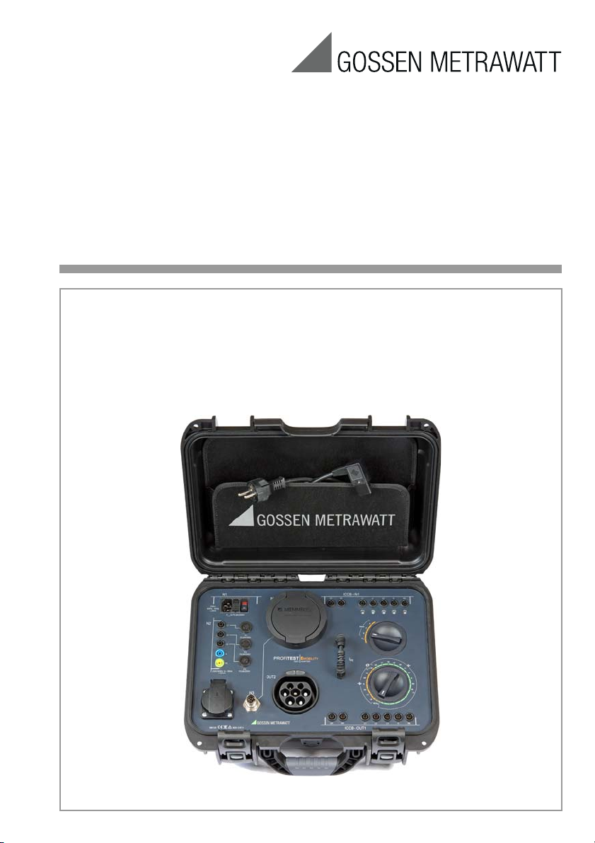
Operating Instructions
PROFITEST⏐EMOBILITY
Adapter for Standards-Compliant Testing of Single and 3-Phase,
Mode 2 and 3 Charging Cables with Simulation of Faults
Important
Read carefully before use!
Keep on file for future reference!
3-349-981-15
4/2.18
Please observe the manufacturer‘s details
on the devices under test!
1
2
3
4
5
6
7
8
9
10
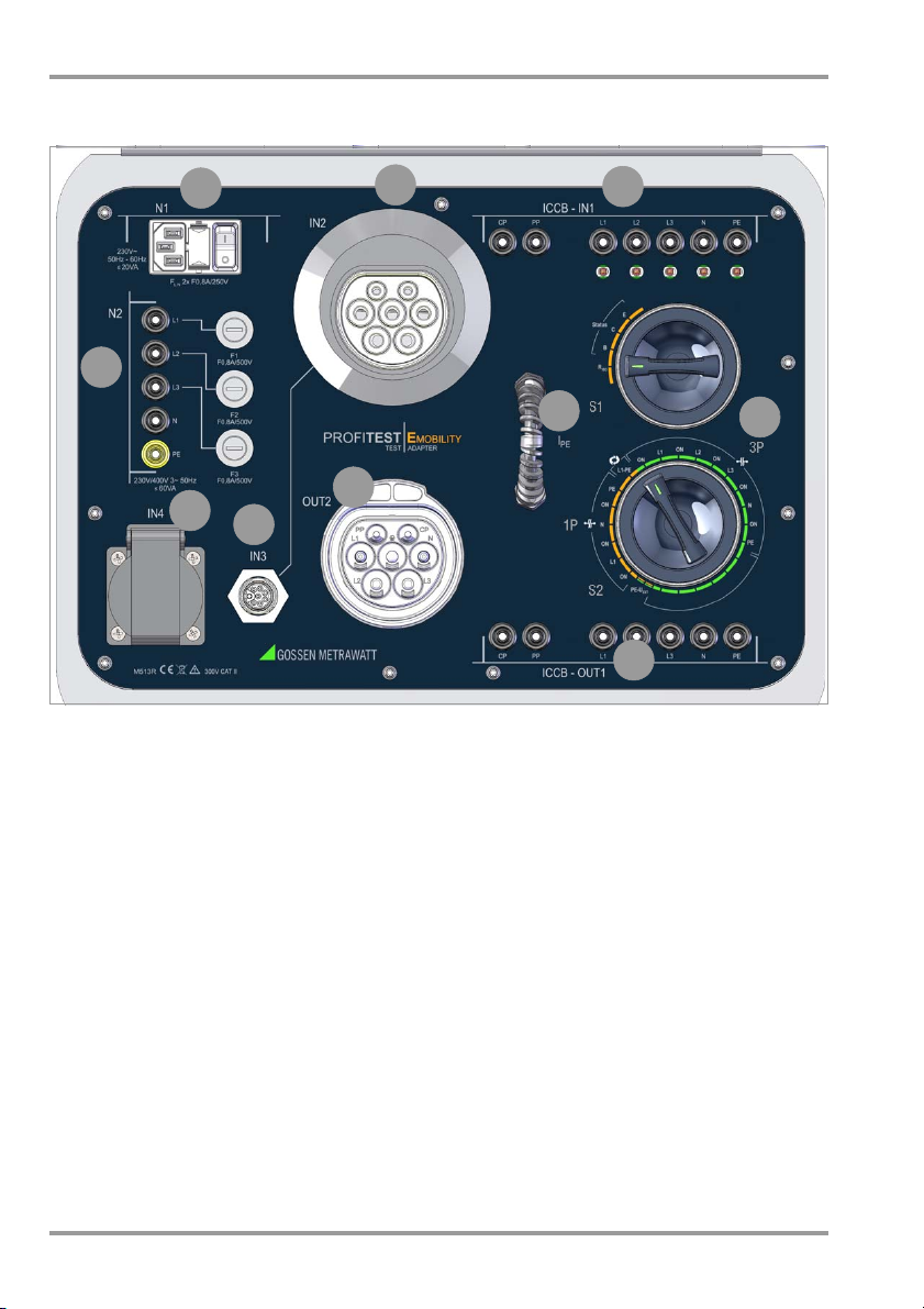
PROFITEST⏐EMOBILITY Connections Overview
Connections Overview
1 N2: Input sockets for 3-phase mains
connection with the help of a CEE
adapter (16 A, 32 A with five 4 mm
safety sockets) and mains connection
fuses F1, F2 and F3 for the 3 phases
2 N1: Inlet plug for mains connection,
mains connection fuses F
3 IN2: Socket (MENNEKES) for connecting
a 3-phase, mode 3 charging cable
(charging station end) via a type 2
charging plug
4 ICCB-IN1*: Input sockets wired parallel to
connection sockets IN2, IN3 and IN4 for
connecting a test instrument for protective conductor and insulation measurement
for L and N
LN
* ICCB = in-cable control box: control box inside
the mode 2 charging cable
2 GMC-I Messtechnik GmbH
5 Rotary selector switches (S1 and S2):
See description on page 3.
6 ICCB-OUT1*: Charging cable output sock-
ets wired parallel to OUT2 for connecting
a test instrument for protective conductor and insulation measurement
7 IN2: Socket (MENNEKES) for connecting
a mode 2 charging cable (vehicle end)
via a type 2 charging plug
8 IN3: Input socket in order to be able to
connect a charging cable with specific
plug per IEC 62196 or CEE plug
(charging station end) via adapter
9 IN4: Earthing contact input socket for
connecting the supply plug of a singlephase, mode 2 charging cable (charging
station end)
10
IPE: Loop for measuring protective conduc-
tor current with a current clamp transformer
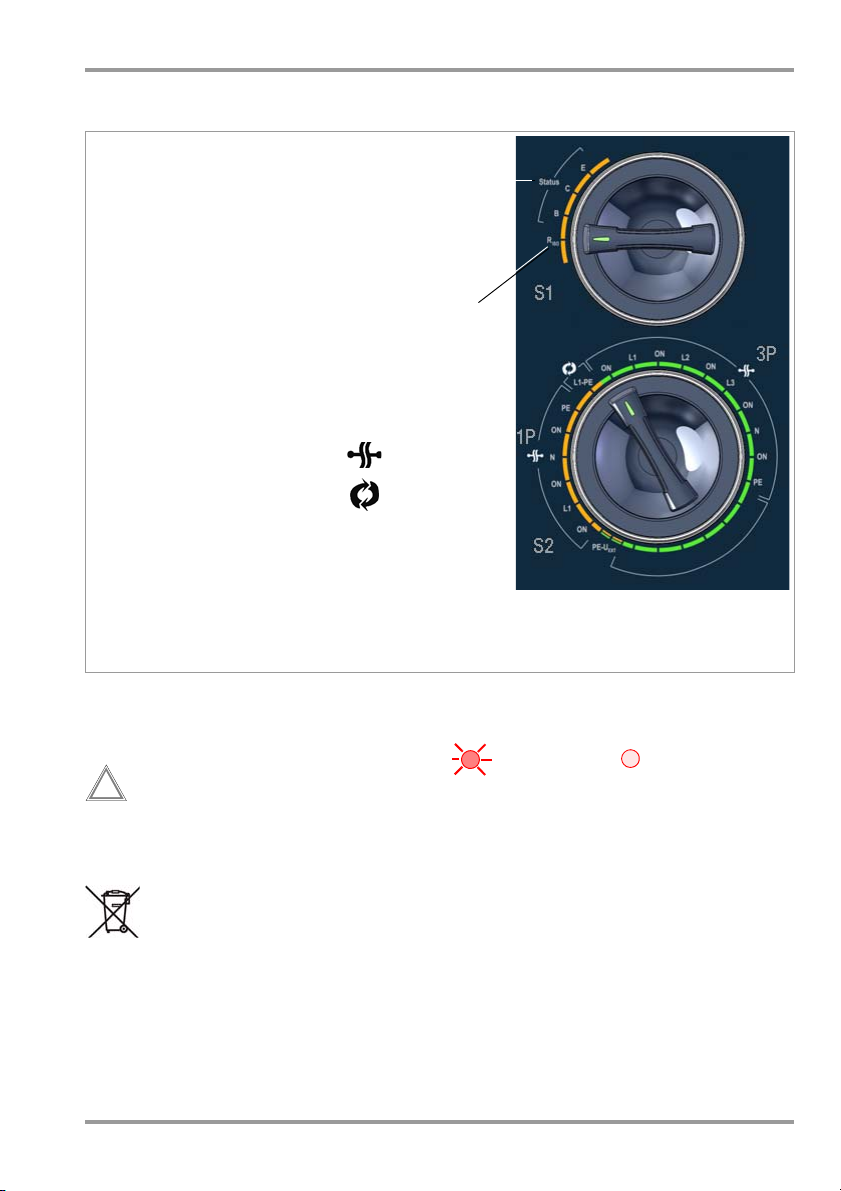
Fault Selection
Interrupted
Reversed wires
Mains disconnect, mode 2/3 charging cable
– For RISO measurement
Mains connect, mode 2 charging cable
– For fault simulation
– For R
PE
measurement
– For tripping test with I
Nom
and measurement of time to trip
Orange switch positions: testing at single-phase, mode 2/3 cables
Green switch positions: testing at 3-phase, mode 2/3 cables
Top S wit ch
Bottom Switch
Status B, C, E
Riso
phase
!
PROFITEST⏐EMOBILITY Operating Overview – Symbols – Scope of Delivery
Operating Overview
Meanings of Symbols on the Instrument
300 V CAT II
GMC-I Messtechnik GmbH 3
Maximum permissible voltage
and measuring category between
connections and ground
Warning concerning a point of
danger (attention: observe documentation!)
CE conformity marking
This device may not be disposed
of with the trash.
Further information regarding the
WEEE mark can be accessed on
the Internet at www.gossenmetrawatt.com by entering the
search term “WEEE”.
Meanings of Symbols in the Operating Instructions
LED L1, L2, L3, N or PE at test adapter
Scope of Delivery
1 Test adapter in case
1 Mains power cable
1 Set of operating instructions
LED on LED off

PROFITEST⏐EMOBILITY Table of Contents – Safety Precautions
Table of Contents Page
1 Safety Precautions .....................................4
2 Applications ...............................................6
3 Initial Startup .............................................7
3.1 Mains Connection ........................................7
3.2 Testing the LEDs ..........................................7
3.3 Connecting the Mode 2/3 Charging Cable ......7
4 Measurement with Test Instruments .........8
Measuring Protective Conductor Resistance (Rlo) ........8
4.1
4.1.1 Mode 2 Charging Cable ........................................8
4.1.2 Mode 3 Charging Cable ........................................8
4.2 Measuring Insulation Resistance (RISO) ..........8
4.3 Tripping Test with Nominal Residual Current and
Measurement of Time to Trip at Mode 2
Charging Cable ............................................9
5 Measuring RC ............................................9
6 Protective Conductor Current Measurement
) at Mode 2 Charging Cable .................9
(I
PE
7 Fault Simulation .......................................10
7.1 Mode 2 Charging Cable
(single-phase) ...........................................10
7.1.1 Simulated Interruption ........................................10
7.1.2 Simulated Wire Reversal ....................................10
7.1.3 Simulation of PE to Phase – PE-U
7.2 Mode 2 Charging Cable
(single-phase) ...........................................11
7.2.1 Simulated Interruption ........................................11
7.2.2 Simulation of PE to phase ....................................12
8 Characteristic Values ...............................13
9 Maintenance ............................................14
9.1 Housing Maintenance .................................14
9.2 Technical Safety Inspections
Testing per DGUV Rule 3 ............................14
9.2.1
Testing Protective Conductor Resistance R
9.2.2 Testing Insulation Resistance ...............................15
9.2.3 Touch Current Measurement ...............................15
9.3 Fuse Replacement ......................................16
9.4 Return and Environmentally Sound Disposal .16
10 Repair and Replacement Parts Service
Calibration Center and Rental Instrument
Service .....................................................16
11 Product Support .......................................16
EXT ...............10
PE ...............14
1 Safety Precautions
The test adapter has been manufactured
and tested in accordance with the following
safety regulations:
IEC/EN 61010-1/VDE 0411-1,
IEC/EN 61577/VDE 0413-2,-4/
DIN EN 61557-16/VDE 0413-16
Safety of the operator, as well as that of the
test adapter and the charging cable, is only
assured when it’s used for its intended purpose.
Read the operating instructions carefully and
completely before placing your test instrument
into service. Follow all instructions contained
therein. Make sure that the operating instructions
are available to all users of the instrument.
Read the operating instructions for the respective
test instrument as well, in particular the sections
concerning the R
surements, as well as the tripping test.
Tests may only be performed by a qualified
electrician, or under the supervision and
direction of a qualified electrician. The user
must be instructed by a qualified electrician
concerning performance and evaluation of
the test (see also training seminars listed at
www.gossenmetrawatt.com).
, R
and time-to-trip mea-
PE
ISO
4 GMC-I Messtechnik GmbH
Attention!
!
PROFITEST⏐EMOBILITY Safety Precautions
Observe the following safety precautions:
• The instrument may only be connected to
electrical systems with a maximum of 230/
400 V which comply with applicable safety
regulations (e.g. IEC 60346, VDE 0100)
and are protected with a fuse or circuit
breaker with a maximum rating of 16 A.
•The test adapter may only be used for test-
ing mode 2 and 3 charging cables.
• No power consuming devices may be con-
nected to any of the sockets.
• Measurements within electrical systems
are prohibited.
• Make certain that the measurement
cables are in flawless condition, e.g. no
damage to insulation, no cracks in
cables or plugs etc.
• When using a test probe with coil cord
(PROFITEST MXTRA):
Grip the tip of the test probe firmly, for
example during insertion into a jack
socket. Tensioning at the coil cord may
otherwise cause the test probe to snap
back resulting in possible injury.
Insulation resistance can only be
measured at voltage-free objects:
R
switch position.
ISO
• Do not touch the insulation measuring
instrument’s test probes during insulation resistance measurements!
• Please observe the manufacturer‘s
details on the devices under test!
Fuse Replacement
All fuses for neutral and phase conductors
are accessible from the outside (see section
9.3). The fuses may only be replaced when
the instrument is voltage-free, i.e. the instrument must be disconnected from mains
supply power and may not be connected to
a measuring circuit. The fuse type must
comply with the specifications in the technical data or the labeling on the instrument
(see section 8).
Opening the Instrument / Repairs
The test adapter may only be opened by
authorized, trained personnel from GMC-I
Service GmbH in order to ensure flawless
operation and to assure that the guarantee is
not rendered null and void.
Even original replacement parts may only be
installed by authorized, trained personnel
from GMC-I Service GmbH.
If it can be ascertained that the test adapter
has been opened by unauthorized personnel, no guarantee claims can be honored by
the manufacturer with regard to personal
safety, measuring accuracy, compliance
with applicable safety measures or any consequential damages.
The test adapter may not be used:
• If external damage is apparent, for example if parts which conduct dangerous
touch voltage are freely accessible, if its
LEDs are defective (voltage at the ICCB-
IN1 sockets would no longer be indicated
in this case)
• If the seal or sealing lacquer has been
removed as the result of repairs or
manipulation carried out by an unauthorized/non-certified service provider
• With damaged connection and/or measurement cables, e.g. interrupted insulation or kinked cable
• If it no longer functions flawlessly
• After extraordinary stressing due to
transport
In such cases, the test adapter must be
removed from operation and secured
against unintentional use.
GMC-I Messtechnik GmbH 5
 Loading...