

Page 1
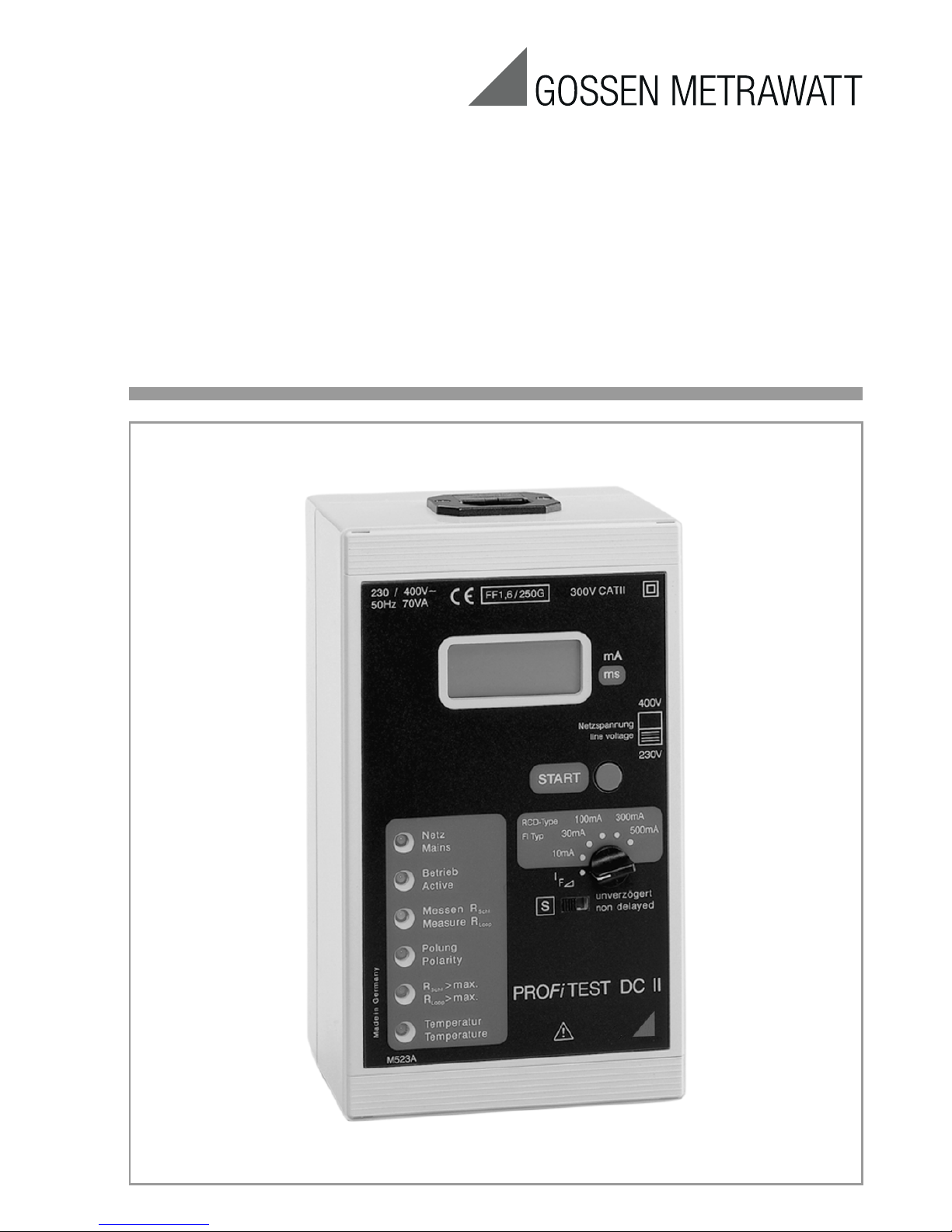
Operating Instructions
PROFiTEST DC-II
Test Instrument for the Suppression of RCCB Tripping
and for Tripping Tests of DC Components
in AC-DC Sensitive RCCBs
3-348-973-37
7/5.14
Page 2
2 GMC-I Messtechnik GmbH
Contents Page
1 Safety Precautions .....................................2
2 Description .................................................3
2.1 Loop Resistance Measuring Mode with the
PROFiTEST... with Suppression of RCCB Tripping ...3
2.2 Tripping Test Operating Mode
for AC-DC Sensitive RCCBs ...................................3
2.2.1 With Rising DC Residual Current and Measurement of
Tripping Current for Undelayed RCCBs ...................3
2.2.2 With Rising DC Residual Current and
Measurement of Tripping Current for
Selective or Short-Time-Delay RCCBs ....................3
2.2.3 With Constant DC Residual Current and Measurement
of Time to Trip ......................................................4
3 Connecting the PROFiTEST DC-II Test
Instrument to the System Under Test ........4
3.1 Testing in Systems with Neutral Conductor .............4
3.2 Testing in Systems without Neutral Conductor ........4
4 Operation ...................................................5
4.1 Loop Resistance Measurement Mode
with the PROFiTEST... with
Suppression of RCCB Triggering ............................5
4.2 Tripping Test Operating Mode
for DC Components in AC-DC Sensitive RCCBs .......5
4.2.1 With Rising DC Residual Current
and Measurement of Tripping Current
for Undelayed RCCBs ............................................5
4.2.2 With Rising DC Residual Current
and Measurement of Tripping Current
for Delayed RCCBs ................................................6
4.2.3 With Constant DC Residual Current
and Measurement of Time to Trip
for Undelayed RCCBs ............................................6
5 Characteristic Values .................................6
6 Maintenance ..............................................7
6.1 Internal Fuse ........................................................7
6.2 External Fuse ........................................................7
6.3 Housing ...............................................................7
6.4 Recalibration ........................................................7
6.5 Return and Environmentally Sound Disposal ...........8
7 Repair and Replacement Parts Service
Calibration Center
and Rental Instrument Service ..................8
8 Product Support .........................................8
1 Safety Precautions
The PROFiTEST DC-II test instrument has been
manufactured in accordance with safety regulations EN 61010-1,
VDE 0411-1 and IEC 61010-1.
If used for its intended purpose, the safety of both
the operator and the instrument is assured. Their
safety is however not assured,
if the test instrument
is operated inco
rrectly or handled improperly.
The test instrument should only be connected to
the mains as long as is necessary to perform the
desired measurement, in order to avoid unnecessarily high temperatures within the instrument.
Attention!
!
Always be certain to select the correct
line voltage when operating the test instrument (voltage selector switch at the
right hand side of the housing labelled:
230/400 V).
Opening the instrument / repairs
The instrument may only be opened by authorized, trained personnel in order to ensure flawless
operation and to assure that the guarantee is not
rendered null and void.
Even original replacement parts may only be
installed by authorized, trained personnel.
If it can be ascertained that the instrument has
been opened by unauthorized personnel, no guarantee claims can be honored by the manufacturer
with regard to personal safety, measuring accuracy, compliance with applicable safety measures
or any consequential damages.
Any warranty claims will be forfeited when the
warranty seal has been damaged or removed.
Meanings of symbols on the instrument
Warning concerning a point of danger
(Attention: observe documentation!)
Protection class II device
EU seal of approval
This device may not be disposed of with
the trash. Further information regarding
the WEEE mark can be accessed on the
Internet at www.gossenmetrawatt.com
by entering the search term “WEEE”.
Meaning of symbols in the operating instructions
Selective RCCB
Pulse-controlled RCCB
AC-DC sensitive RCCB
I
F
Rising DC residual current
!
S
Page 3
GMC-I Messtechnik GmbH 3
2Description
2.1 Loop Resistance Measuring Mode
with the PROFiTEST...
with Suppression of RCCB Tripping
The PROFiTEST DC-II test instrument allows for
the measurement of loop resistance in TN
systems with RCCBs (10/30/100/300/500 mA
nominal residual current) without DC sensitive
components.
The test instrument generates a DC residual current which saturates the magnetic circuit of the
RCCB.
The PROFiTEST 0100S/S-I I,PROFi TEST 2 or
PROFiTEST
C superimposes a measuring current
which demonstrates only half-waves of like polarity. The RCCB cannot detect this measuring current and can thus no longer be tripped during
measurement.
2.2 Tripping Test Operating Mode
for AC-DC Sensitive RCCBs
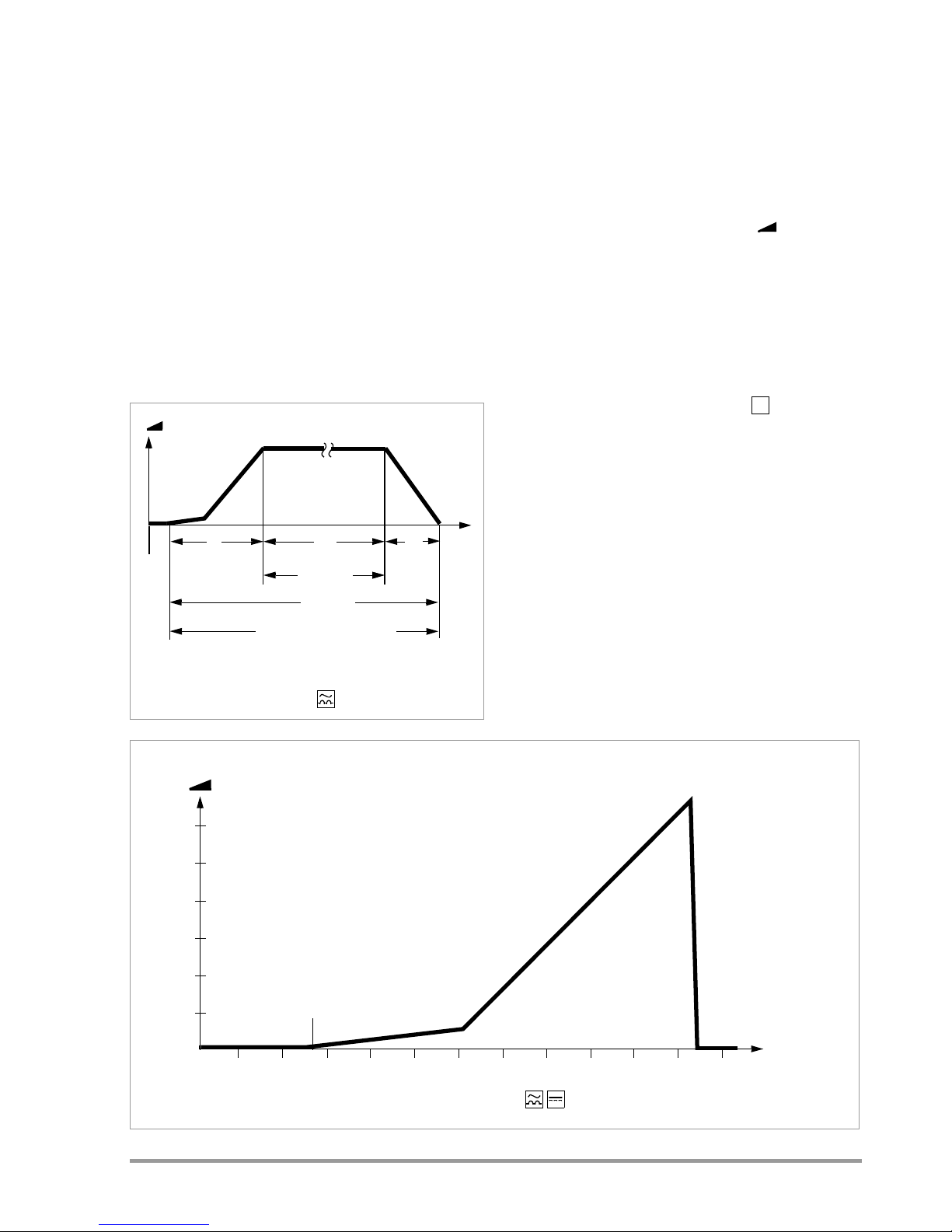
2.2.1 With Rising DC Residual Current and
Measurement of Tripping Current
for Undelayed RCCBs
A slowly rising direct current is applied to N and
PE with the selector switch in the I
F
position.
The measured current value is displayed continuously. When the RCCB is tripped, the last measured current value is stored for several seconds
and can be read from the display.
2.2.2 With Rising DC Residual Current and
Measurement of Tripping Current for
Selective or Short-Time-Delay RCCBs
The current ramp demonstrates a gradual overall
rise with the selector switch in the position.
Test duration is considerably longer. Use this
selector switch position for testing tripping current
for selective or short-time-delay AC-DC sensitive
RCCBs.
Start
t1 t3
Measure
t2
Active
RCCB inoperable!
t
I
F
/mA
Suppression of RCCB Tripping
with Pulse-Controlled RCCB
S
0.4 0.8 1.0 1.6 2.0 2.4 2.8 3.2 3.6 4.0 4.4 4.8
100
200
300
400
500
600
I
F
/mA
t/s
A residual current curve with a lesser slope
between 0 and 100 mA provides for
enhanced resolution.
Start
Tripping Occurs
A residual current curve with
a steeper slope as of
100 mA allows for more
rapid testing.
Measurement of Tripping Current for AC-DC Sensitive RCCBs
Page 4

4 GMC-I Messtechnik GmbH
2.2.3 With Constant DC Residual Current and Measurement of Time to Trip
With the selector switch set to the respective
nominal residual current, twice the nominal current is applied to N and PE. Time to trip is measured and displayed for the RCCB.
3 Connecting the PROFiTEST DC-II Test Instrument to the System Under Test
3.1 Testing in Systems with Neutral Conductor
Perform testing at an earthing contact outlet with
the provided earthing contact device connector
cable in systems which have both a neutral and a
protective conductor.
➭ Set the voltage selector switch to 230 V (at
the right hand side of the housing labelled:
230/400 V).
Note!
If the voltage selector switch has been set
to 400 V, the test instrument is inoperable
and only random values appear at the
display.
➭ Perform testing as described in chapter 4.2.1.
3.2 Testing in Systems without Neutral Conductor
Proceed as follows in order to test RCCBs in systems without a neutral conductor:
➭ Set the voltage selector switch to 400 V.
➭ Use the Z523A test adapter with three test
probes.
➭ Connect the test probes as follows:
➭ Connect the black test probe to a phase
conductor downstream from the RCCB.
➭ Connect the blue test probe to a different
phase conductor downstream from the
RCCB.
➭ Connect the red test probe to the same
phase conductor as the blue test probe has
been connected to, but upstream from the
RCCB.
➭ We recommend performing the test on all
three phases.
Attention!
!
When a connection is made between two
phases, the voltage selector switch must
be set to 400 V. Otherwise the internal
device fuse will blow!
10 20 40 50
100
200
300
400
500
600
I
Test
/mA
t/ms
Start
Tripping Occurs
30 60 70
Measurement of Time to Trip
for AC-DC Sensitive RCCBs
L1
L2
L3
N
PE
red
blue
black
!
400 V
230 V
L1
L2
L3
red
blue
black
!
400 V
230 V
Page 5

GMC-I Messtechnik GmbH 5
4Operation
Overview
4.1 Loop Resistance Measurement Mode
with the PROFiTEST... with
Suppression of RCCB Triggering
➭ Connect the PROFiTEST DC-II to the system
under test:
The “Mains” lamp lights up green. The display
value is equal to or close to 0.
➭ If the polarity lamp lights up, reverse the poles
at the mains connection.
➭ Connect the PROFiTEST... via the earthing
contact outlet at the PROFiTEST DC-II mains
plug. Select positive half-wave for the R
Loop
/
Z
Loop
range (loop resistance).
➭ Set the selector switch to the I
F
position
and the slide switch to “undelayed”.
➭ Press the “START” key at the
PROFiTEST DC-II.
The “Active” lamp lights up.
➭ The “Measuring” lamp lights up after approxi-
mately 4 to 5 s.
The RCCB is disabled (disabling of the RCCB
lasts for approximately 30 s).
Magnetizing current is displayed in mA.
➭ Measure loop resistance with the
PROFiTEST... with the switch in the “R
Loop
/
Z
Loop
“ position after “positive half-wave to
earth” has been selected in the menu.
➭ After the measurement has been completed,
wait until the “Measuring” lamp has gone out,
followed by the “Active” lamp about 6 s later.
Disconnect the instrument from the system.
Attention!
!
The RCCB is disabled during operation and
measurement.
The RCCB must be tripped after measure-
ment with the PROFiTEST DC-II in order
to test for proper functioning.
Either activate the test button at the
RCCB, or perform a tripping test with the
PROFiTEST....
Important Notes
If the “R
Loop/ZLoop
> max.” lamp lights up, loop
resistance is greater than approximately 8 . Cor-
rect measurement is impossible in this case. The
fact that the lamp may flicker during measurement
is of no consequence.
If the “Temperature” lamp lights up, disconnect
the PROFiTEST DC-II from the mains and allow it
to cool.
4.2 Tripping Test Operating Mode
for DC Components in AC-DC Sensitive RCCBs
4.2.1 With Rising DC Residual Current
and Measurement of Tripping Current
for Undelayed RCCBs
➭ Connect the PROFiTEST DC-II to the system
under test:
The “Mains” lamp lights up green. The display
value is equal to or close to 0.
➭ If the polarity lamp lights up, reverse the poles
at the mains connection.
➭ Set the function selector switch to the I
F
position and the slide swItch to “undelayed”.
➭ Press the “START” key at the
PROFiTEST DC-II.
The “Active” lamp lights up.
Measurement Results:
a) Current rises until the RCD is tripped. Tripping
current is subsequently displayed for approximately 5 s.
or
b) If the RCD fails, current rises until saturation
current has been reached.
Saturation current is displayed in mA for
approximately 30 s, after which the displayed
current value again approaches 0.
Measurement RCCB Type Selector Switch Position Display
Loop Resistance Standard
I
F
undelayed PROFiTEST...
Triggering Current AC-DC Sensitive
I
F
undelayed PROFiTEST DC-II
Triggering Current AC-DC Sensitive, Delayed
I
F
PROFiTEST DC-II
Time to Trip AC-DC Sensitive 10/30/100/300/500 mA PROFiTEST DC-II
S
Page 6

6 GMC-I Messtechnik GmbH
4.2.2 With Rising DC Residual Current
and Measurement of Tripping Current
for Delayed RCCBs
Set the slide switch to the position in order to
determine tripping current for selective or shorttime-delay AC-DC sensitive RCCBs.
➭ Connect the PROFiTEST DC-II to the system
under test:
The “Mains” lamp lights up green. The displayed value is equal to or close to 0.
➭ If the polarity lamp lights up, reverse the poles
at the mains connection.
➭ Set the function selector switch to the I
F
position and the slide switch to .
➭ Press the “START” key at the
PROFiTEST DC-II.
The “Active” lamp lights up.
Measurement Results
Current rises continuously, but gradually, until the
RCD is tripped. Tripping current is then displayed
in mA for about 5 s.
This test may last as long as 1 minute.
4.2.3 With Constant DC Residual Current
and Measurement of Time to Trip
for Undelayed RCCBs
➭ Connect the PROFiTEST DC-II to the system
under test:
The “Mains” lamp lights up green. The displayed value is equal to or close to 0.
➭ If the polarity lamp lights up, reverse the poles
at the mains connection.
➭ Set the function selector switch to the 10, 30,
100, 300 or 500 mA position, depending
upon the rated current for the RCCB.
➭ Set the slide switch to the “undelayed” posi-
tion.
➭ Press the “START” key at the
PROFiTEST DC-II.
The “Active” lamp lights up and remains lit
until testing has been completed.
Time to trip is continuously displayed.
Measurement Results
a) Time to trip is displayed in ms for about 5 s
after tripping occurs or
b) If the RCD fails, or if the selected nominal
residual current value is too small, measurement is performed for a period of up to
2000 ms. Time overflow is indicated thereafter
by means of a flush left 1 at the display.
Note!
Test current is two times nominal residual
current in accordance with
DIN VDE 0664.
The AC components of AC-DC sensitive RCCBs
are to be tested with the PROFiTEST....
5 Characteristic Values
Line Voltage 230/400 V
(–10%, +25 %), 50 Hz
DC Residual Current
for Suppression of
RCCB Tripping DC 1.25 A +30%
* limited by means of maximum DC residual current (see above)
Temperature Ranges / Climatic Category
Operating Temperatures –10 C ... +50 C
Storage Temperatures –20 C ... +60 C
Electrical Safety
Protection Class II per IEC 61010-1/
EN 61010-1/
VDE 0411-1
Operating Voltage 300 V
Test Voltage 3.7 kV 50 Hz
Measurement Category II
Pollution degree 2
Internal Fuse electronic (PTC)
External Fuse cartridge fuse link
in plug:
5 mm x 20 mm:
FF 1.6/250
S
S
Measure-
ment
Measuring
Range
Measuring
Accuracy
Measurement
uncertainty
Tripping
Current
1 ... 1999 mA* (4 % rdg. + 5 d) (8% rdg. + 5 d)
Time to
Trip
2 ... 1999 ms (3 % rdg. + 5 d) (6 % rdg. + 5 d)
Selector Switch Position
for Measurement of Time to Trip
(nominal residual current)
Test Cur re n t
10 mA 20 mA +10%
30 mA 60 mA +10%
100 mA 200 mA +10%
300 mA 600 mA +10%
500 mA 1000 mA +10%
Page 7

GMC-I Messtechnik GmbH 7
Electromagnetic Compatibility (EMC)
Product standard DIN EN 61326:2006
Inputs and Outputs
The mains connection provides for power supply
and simultaneously functions as an output for test
and magnetizing current.
Mechanical Design
Protection housing: IP 40 per
DIN VDE 0470
Extract from table on the meaning of IP codes
Dimensions L x W x D:
205 mm x 120 mm x
100 mm (without power
cable)
Weight 1.5 kg (without power
cable)
6 Maintenance
6.1 Internal Fuse
An internal fuse protects the test instrument
against operator error.
If the instrument is overloaded with 400 V instead
of 250 V mains power, the electronic fuse is
tripped. LEDs may still be illuminated and characters may still appear at the display, but the instrument will not function if a test is started.
In such a case, wait for approximately 2 minutes
until the protective circuit has been deactivated
and the test instrument is once again ready for
operation.
6.2 External Fuse
The device connector cable is equipped with a
fuse.
Attention!
!
Be absolutely certain that only the specified fuses are used! If fuses are used
which demonstrate other blowing characteristics, rated current or breaking capacity, danger exists for the user, as well as
for damping diodes, resistors and other
components.
The use of repaired fuses or short-circuiting the
fuse holder is prohibited.
6.3 Housing
The test instrument may only be cleaned with a
soft cloth or brush. If the housing should become
statically charged, discharging may be performed
with an antistatic agent or a damp cloth.
6.4 Recalibration
The measuring tasks performed with your instrument, and the stressing it’s subjected to, influence
aging of its components and may result in deviation from the specified levels of accuracy.
In the case of strict measuring accuracy requirements, as well as in the event of use at construction sites with frequent stress due to transport and
considerable temperature fluctuation, we recommend a relatively short calibration interval of once
per year. If your instrument is used primarily in the
laboratory and indoors without considerable climatic or mechanical stressing, a calibration interval of once every 2 to 3 years is sufficient as a rule.
During recalibration* at an accredited calibration
laboratory (DIN EN ISO/IEC 17025), deviations
from traceable standards demonstrated by your
measuring instrument are documented. Ascertained deviations are used to correct displayed
values during later use of the instrument.
We would be happy to perform DAkkS or factory
calibration for you at our calibration laboratory.
Further information is available at our website:
www.gossenmetrawatt.com ( Company
DAkkS Calibration Center or FAQs Questions and Answers Regarding Calibration).
Recalibration of your instrument at regular intervals is essential for the fulfillment of requirements
according to quality management systems per
DIN EN ISO 9001.
* Examination of the specification, as well as adjustment,
are not included in calibration. However, in the case of
our own products, any required adjustment is performed and adherence to the specification is confirmed.
Interference
Emission
EN 55022 class B
Interference
Immunity
Test Valu e
EN 61000-4-2 Contact/Atmosphere - 4 kV/8 kV
EN 61000-4-3 10 V/m
EN 61000-4-4 Mains connection - 2 kV
EN 61000-4-5 Mains connection - 1 kV
EN 61000-4-6 Mains connection - 3 V
EN 61000-4-11 0.5 period / 100%
IP XY
(1st digit X)
Protection against
foreign object entry
IP XY
(2nd digit Y)
Protection against
the penetration of
water
4 1,0 mm
0 not protected
Page 8

Edited in Germany • Subject to change without notice • A pdf version is available on the internet
GMC-I Messtechnik GmbH
Südwestpark 15
90449 Nürnberg •
Germany
Phone +49 911 8602-111
Fax +49 911 8602-777
E-Mail info@gossenmetrawatt.com
www.gossenmetrawatt.com
6.5 Return and Environmentally Sound Disposal
The instrument is a category 9 product (monitoring and control instrument) in accordance with
ElektroG (German electrical and electronic device
law). This device is RoHS-compliant. Furthermore,
we make reference to the fact that the current status in this regard can be accessed on the Internet
at www.gossenmetrawatt.com by entering the
search term WEEE.
We identify our electrical and electronic
devices (as of August 2005) in accordance with WEEE 2002/96/EC and
ElektroG using the symbol shown at
the right per DIN EN 50419.
These devices may not be disposed of with the
trash.
Please contact our service department regarding
the return of old devices (see address in
section 7).
7 Repair and Replacement Parts Service
Calibration Center*
and Rental Instrument Service
When you need service, please contact:
GMC-I Service GmbH
Service Center
Thomas-Mann-Str. 20
90471 Nuremberg, Germany
Phone +49 911 817718-0
Fax +49 911 817718-253
E-mail service@gossenmetrawatt.com
www.gmci-service.com
This address is only valid in Germany.
Please contact our representatives or subsidiaries
for service in other countries.
* DAkkS Calibration Laboratory
for Electrical Quantities D-K-15080-01-01
accredited per DIN EN ISO/IEC 17025
Accredited measured quantities: direct voltage, direct
current values, DC resistance, alternating voltage,
alternating current values, AC active power, AC apparent power, DC power, capacitance, frequency and
temperature
Competent Partner
GMC-I Messtechnik GmbH is certified in accordance with DIN EN ISO 9001:2008.
Our DAkkS calibration laboratory is accredited by
the Deutsche Akkreditierungsstelle GmbH
(National accreditation body for the Federal
Republic of Germany) in accordance with DIN EN
ISO/IEC 17025:2005 under registration number
D-K-15080-01-01.
We offer a complete range of expertise in the field
of metrology: from test reports and proprietary cali-
bration certificates right on up to DAkkS calibration
certificates.
Our spectrum of offerings is rounded out with free
test equipment management.
An on-site DAkkS calibration station is an integral part
of our service department. If errors are discovered
during calibration, our specialized personnel are
capable of completing repairs using original
replacement parts. As a full service calibration laboratory, we can calibrate instruments from other
manufacturers as well.
8 Product Support
When you need support, please contact:
GMC-I Messtechnik GmbH
Product Support Hotline
Phone +49 911 8602-0
Fax +49 911 8602-709
E-mail support@gossenmetrawatt.com
 Loading...