

Gossen metrawatt Secutest Clip, Profitest Clip User Manual
3-349-887-03
1/1.17
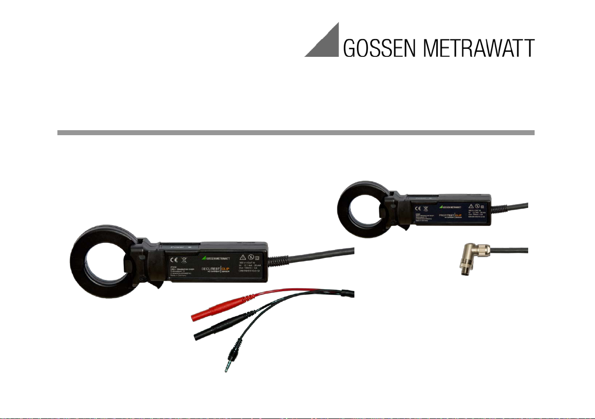
SECUTEST CLIP and PROFITEST CLIP
Leakage Current Clamp Meters for SECUTEST PRO and PROFITEST PRIME

GMC-I Messtechnik GmbH
Notes Regarding these Operating Instructions
Texts, illustrations and technical specifications have been prepared with great
care. Errors can nevertheless not be entirely ruled out. The manufacturer of the
leakage current clamp meter cannot accept any legal responsibility or liability for
incorrect entries and their consequences!
Read these operating instructions carefully and co m pletely before using the
leakage current clamp meter!
Warnings and warning symbols in the operating instructions and on the leakage
current clamp meter are intended to alert the user to risks and hazards!
2

GMC-I Messtechnik GmbH
Warnings and Safety Precautions
Read these operating instructions carefully and co m pletely before using the
necessary for safe operation and use of the leakage current clamp meter.
The SECUTEST CLIP / PROFITEST CLIP leakage current clamp meter has been
directives.
Safety of the operator, as well as that of the leakage current clamp meter, is only
assured when the device is used for its intended purpose.
The SECUTEST CLIP / PROFITEST CLIP leakage current clamp meter may only be
intended purpose (see also section 2, “Terminology” )!
leakage current clamp meter! They contain information and instructions which are
manufactured and tested in accordance with safety regulations
IEC 61557-13/-16, IEC 61010-1 and IEC 61010-2-032.
The CE conformity marking confirms com pliance with the EMC and low-voltage
used by electricians, other qualified persons or accordingly trained persons for its
3
GMC-I Messtechnik GmbH
The following symbols draw the operator’s atte ntion to importa nt information and
instructions which are necessary for safe operation and use of the leakage current
clamp meter.
This symbol is used in the operating instructions in particular to
injury!
This symbol is used in the operating instructions and on the
uninsulated conductors.
This symbol is used in the operating instructions and on the
leakage current clamp meter in order to warn against incorrect
operation!
warn against risks and hazards associated with incorrect
operation!
Disregarding this warning symbol may result in severe or fatal
leakage current clamp meter in particular to warn against risks
and hazards associated with incorrect operation! Disregarding
this warning symbol may result in severe or fatal injury. During
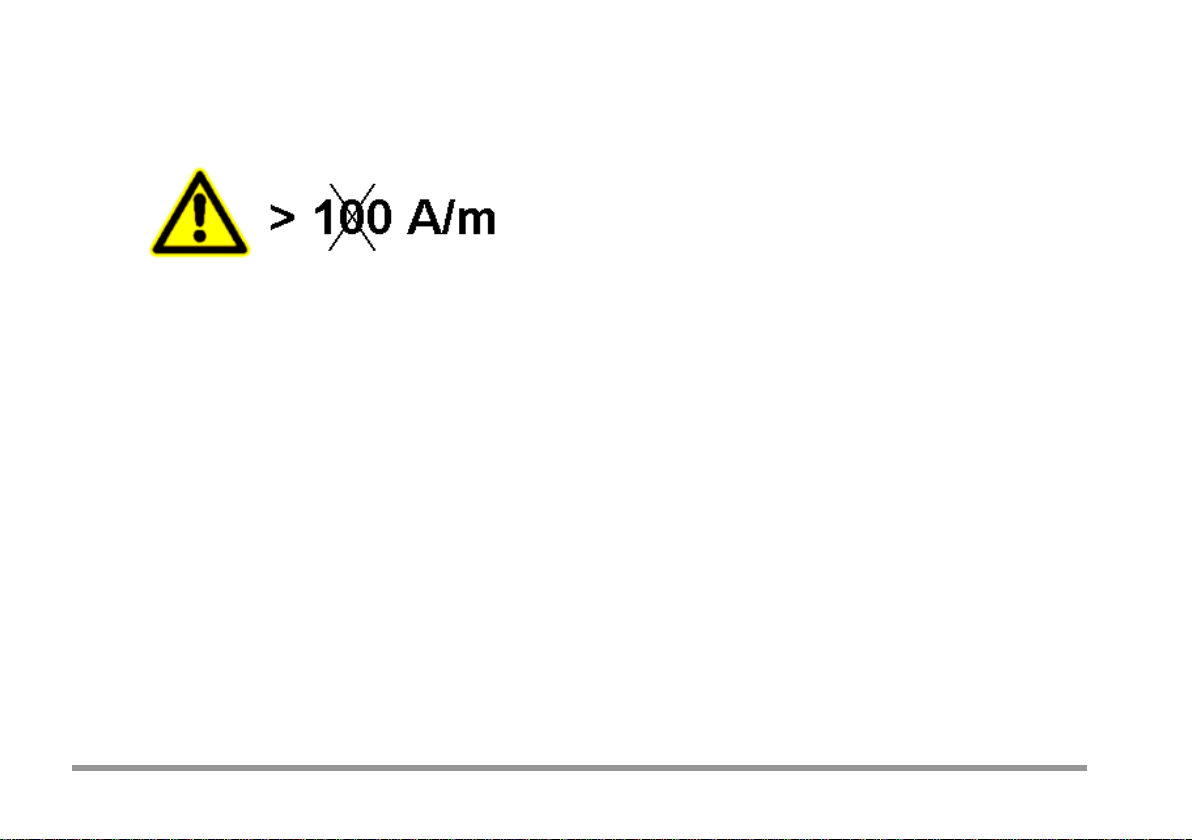
use for its intended purpose, in consideration of the measuring
category, the leakage current clamp meter must not enclose any
4
GMC-I Messtechnik GmbH
This warning symbol on the leakage
current clamp meter makes reference to
class 1.
sensitivity to external magnetic fields.
The field strength of the interfering
magnetic field may not exceed a value
of 100 A/m, which corresponds to use
5

GMC-I Messtechnik GmbH
Opening the Instrument / Repairs
The instrument may only be opened by authorized, trained personnel in order to ensure
flawless operation and to assure that the guarantee is not rendered null and void.
Even original replacement parts may only be installed by authorized, trained personnel.
If it can be ascertaine d that t he instrument has bee n opened by unauthorized personnel, no
guarantee claims can be honored by the manufacturer with regard to personal safety,
measuring accuracy, compliance with applicable safety measures or any consequential
damages.
6

GMC-I Messtechnik GmbH
Table of Contents
1
Applications ...................................................................................................................................... 8
2
Terminology ...................................................................................................................................... 8
3
Operation ......................................................................................................................................... 25
4
Connection Example s .................................................................................................................... 33
5
Calibration ....................................................................................................................................... 36
6
Care and M aintenance .................................................................................................................... 36
7
Guarantee ........................................................................................................................................ 37
8
Return and Environment al ly Sound Di spos al .............................................................................. 38
9
Technical Data ................................................................................................................................ 39
10 Product Support ............................................................................................................................. 44
11 Repair and Replacement Parts Service, Calibration Center and Rental Instrument Service .. 45
7

GMC-I Messtechnik GmbH
1 Applications
When used for its intended purpose, the leakage current clamp
up to 600 V, e.g. at operating equipment.
Leakage Current Clamp Meter
A leakage current clamp meter is a current probe for the
1):2011, appendix A.
meter makes it possible to measure alternating current from 0.1 to
25 mA without interrupting any lines by closing the clamp around
one or more conductors in measuring category III electrical circuits
with up to 300 V between the phase conductor and gro und, e.g. in
build ing inst allations, or measuring category II electrical circuits with
2 Terminology
measurement of leakage current without interrupting the current
path of the measuring circuit. The meter must make it possible to
measure leakage current by means of the direct measuring method
or the differential current method.
The measurement results read out by the leakage current clamp
8
meter must take frequency response of test circuit A1 into
consideration in accordance with DIN EN 61010-1 (VDE 0411-

GMC-I Messtechnik GmbH
Evaluation of frequency response is alrea d y taken into account by
the leakage current clamp meter.
Jaws
The components of the leakage current clamp meter which
enclose the conductor (see figure 3, item 1).
Yoke
The part of the leakage current clamp meter which is placed
field (see figure 3, item 2).
Use for Intended Purpose
The use for which the device is suitable in accordance with the
against operating the device under othe r than normal conditions.
around the conductor to be measured and detects the magnetic
manufacturer’s specifications (i.e. operating instructions).
Use for intended purpose also includes compliance with the
stipulated operating and maintenance conditions, as well as
consideration of foreseeable operating errors.
As a rule, normal conditions are a prerequisite for use for
intended purpose because the operating instructions warn
9

GMC-I Messtechnik GmbH
Measuring Uncertainty
Measuring uncertainty is the specified difference between the
value displayed by the measuring instrument (measured va lue)
measured quantity in the operating range.
Intrinsic Uncertainty
Measuring error of a measuring instrument during operation
Electromagnetic Compatibility
All electrical currents generate electromagnetic fields which can
which also includes other equipment.
or the magnitude of the output signal and the actual value of the
under reference conditions.
cause current to f lo w in other electrical conductors, thus
resulting in interference. The European EMC directive for
electromagnetic compatibility (EN 61326-1) has been
implemented in order to avoid this interference or reduce it to an
absolute minimum.
Electromagnetic compatibility is the ability of a piece of electrical
equipment to function satisfactorily in its electromagnetic
environment without impermissibly influencing this environment,
10
GMC-I Messtechnik GmbH
Stray Field Sensitivity
Influence error caused by a stray magnetic field which
determines the use class (DIN EN 60051-9).
Use Classes
Current probes are subdivided into 3 use classes based on
magnetic fields.
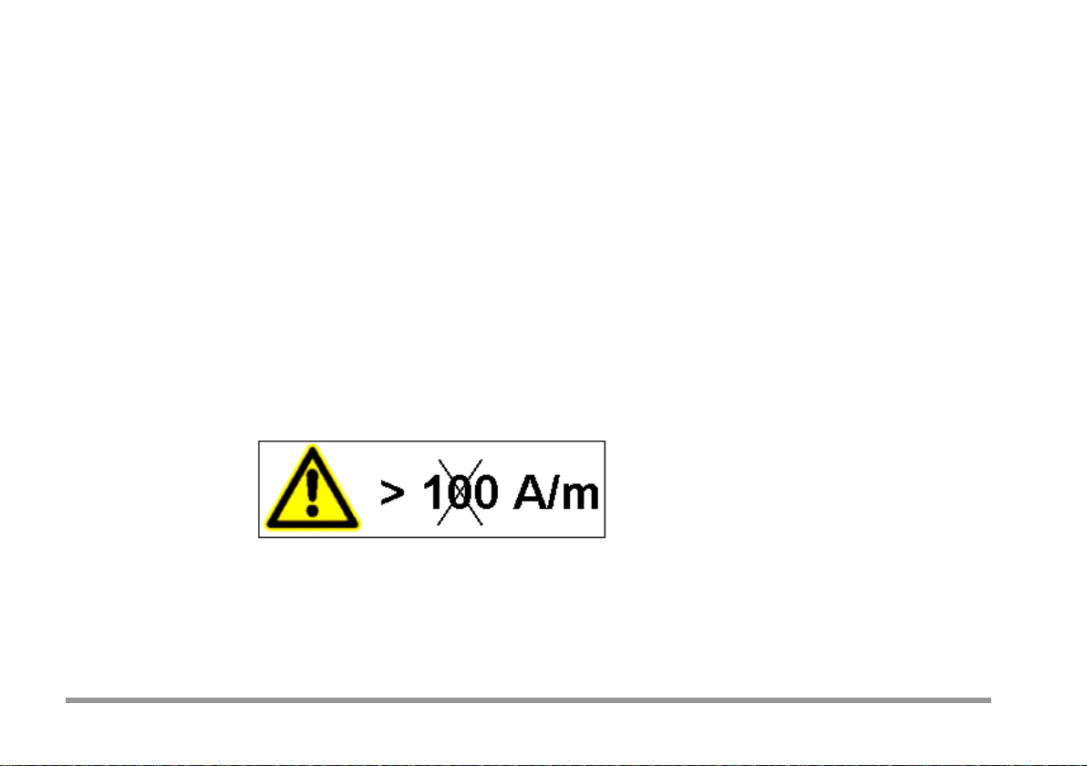
Strength of up to 100 A/m per Use Class 1
sensitivity to low-frequency magnetic fields with frequencies
ranging from 15 to 400 Hz. Current probes of all classes must be
furnished with a framed pictograph (see figure 1) which is plainly
visible to the operator, includes the corresponding symbol in
accordance with DIN EN 61010-1 (VDE 0411-1):2011 and warms
against exceeding the permissible limit value for external
Figure 1: Warning Symbol for Maximum Permissible Field
11

GMC-I Messtechnik GmbH
Use Class 1
Use class 1 current probes must be suitable for use in external
low-frequency magnetic fields, in particular within a frequency
Use Class 2
Use class 2 current probes must be suitable for use in external
Use Class 3
Use class 3 current probes must be suitable for use in external
curren t cla m p meter by me a ns o f a pla inly vis ib l e warning s y m bo l.
range of 15 to 400 Hz, up to a field strength of 100 A/m. The
limit value for the magnetic field must be indicated on the
leakage current clamp meter by means of a plainly visible
warning symbol.
low-frequency magnetic fields, in particular within a frequency
range of 15 to 400 Hz, up to a field strength of 30 A/m. The limit
value for the magnetic field must be indicated on the leakage
current clamp meter by means of a plainly visible warning
symbol.
low-frequenc y ma g ne t ic f ie ld s , in par t ic ula r within a frequency
range of 15 to 400 Hz, up to a field strength of 10 A/m. The lim it
value for the magnetic field must be indicated on the leakage
12

GMC-I Messtechnik GmbH
Electrician / Qualified Person / Trained Person
Only competent persons may use and conduct measurements
with leakage current clamp meters. In this sense, qualified
Electricians
An electrician is a person with suitable technical t raining,
01,
Qualified Persons
A qualified person is someone who posses the technical knowledge
Electrically Trained Persons
An electrically trained person is someone who has been
826-09-02, modified].
persons include:
knowledge and experience which makes it possible to recognize
and avoid the hazards associated with electricity [IEV 826-09modified].
required for testing equipment as a result of vocational training,
work experience and recent vocational activity [German
Occupational Safety Law (BetrSichV)]. Qualified persons are not
subject to any technical directives during the course of their
testing work and may not be disadvantaged by them.
adequately trained by a electric ian, thu s making it possible to
recognize and avoid the hazards associated with electricity [IEV
13
GMC-I Messtechnik GmbH
Field Strength
Field strength designates the strength of and electrical,
Electrical Field Strength
The symbol for electrical field strength is E and its unit of
magnetic or other spatially distributed field at a specified point
in space. Field strength is frequently a vector and is calculated
on the basis of direction and magnitude. Well-known fields
include the
electrical field and the magnetic field.
measure is volts per meter (V/m). It increases along with
voltage U (V) between the charged bodies, and as distance L
(m) between the charged bodies is reduced.
E = U/L [V/m]
14

GMC-I Messtechnik GmbH
Frequency Characteristics of the Human Body
Measuring setup for direct current and sinusoidal alternating
frequency range (below 1000 Hz).
current in accordance with IEC 61010-1, appendix A. This
measuring circuit (low-pass) prevents the measurement of
leakage current in the high-frequency range (as of roughly
1000 Hz). People react especia lly sensitively to the low-
15
 Loading...