

Page 1

Operating Instructions
SYSKONP500, P800, P1500, P3000 and P4500
Computer Controlled Laboratory Power Supplies
3-349-373-03
13/10.16
Page 2

2 GMC-I Messtechnik GmbH
Contents Page
Contents Page
1 Initial Inspection – Warnings . . . . . . . . . . . . . .3
2 Initial Start-Up – Dimensional Drawings . . . . . . 4
2.1
Dimensional Drawing SYSKON P500 / P800 / P1500 . . 4
2.2 Dimensional Drawing SYSKON P3000 / P4500 . . . 5
2.3 Preparing for Operation . . . . . . . . . . . . . . . . . . . . . . 6
2.3.1 Installing the Optional GPIB Interface Module . . . . . . . . . . . 6
2.3.2 Setup as Benchtop Device . . . . . . . . . . . . . . . . . . . . . . . . . 6
2.3.3 Installation to a 19'' Device Cabinet . . . . . . . . . . . . . . . . . . 6
2.3.4 Connection to the Mains . . . . . . . . . . . . . . . . . . . . . . . . . . 6
2.3.5 Connecting Power Consumers . . . . . . . . . . . . . . . . . . . . . . 6
2.3.6 Connection to Computer Interfaces . . . . . . . . . . . . . . . . . . . 6
2.3.7 Driver update (USB device driver) . . . . . . . . . . . . . . . . . . . . 7
2.3.8 Connecting the Analog Interface . . . . . . . . . . . . . . . . . . . . . 7
2.4 Switching the Device On . . . . . . . . . . . . . . . . . . . . . 7
2.4.1 Table of Firmware Versions . . . . . . . . . . . . . . . . . . . . . . . . 8
2.4.2 Response after Power ON with Varying Line Voltage
Ranges (230 V 115 V) . . . . . . . . . . . . . . . . . . . . . . . . . 8
3 Technical Description . . . . . . . . . . . . . . . . . . . .9
4 Technical Data . . . . . . . . . . . . . . . . . . . . . . . .12
4.1 General Data . . . . . . . . . . . . . . . . . . . . . . . . . . . . . 12
4.1.1 Electromagnetic Compatibility . . . . . . . . . . . . . . . . . . . . . 13
4.1.2 Ambient Conditions . . . . . . . . . . . . . . . . . . . . . . . . . . . . . 13
4.2 Mechanical Data . . . . . . . . . . . . . . . . . . . . . . . . . . 14
4.2.1 Terminals (rear panel) . . . . . . . . . . . . . . . . . . . . . . . . . . . 14
4.3 Electrical Data . . . . . . . . . . . . . . . . . . . . . . . . . . . 15
4.3.1 Reference Conditions . . . . . . . . . . . . . . . . . . . . . . . . . . . . 17
5 Controls, Display Elements and Terminals . . .18
5.1 Front Panel SYSKON P500 / P800 / P1500 . . . . . . 18
5.2 Rear Panel P500 / P800 / P1500 . . . . . . . . . . . . . 20
5.3 Front Panel SYSKON P3000, P4500 . . . . . . . . . . . 22
5.4 Rear Panel SYSKON P3000, P4500 . . . . . . . . . . . 24
6 Menu Structure and Parameters . . . . . . . . . . 26
7 Analog Interface . . . . . . . . . . . . . . . . . . . . . . . 28
7.1 Connector pin assignments . . . . . . . . . . . . . . . . . 28
7.2 Auto-sensing mode . . . . . . . . . . . . . . . . . . . . . . . . 30
7.3 Status Signal Outputs . . . . . . . . . . . . . . . . . . . . . . 30
7.4 Regulating Output Voltage . . . . . . . . . . . . . . . . . . 31
7.5 Controlling Output Current . . . . . . . . . . . . . . . . . . 31
7.6 Voltage Monitoring Output . . . . . . . . . . . . . . . . . . 32
7.7 Current Monitoring Output . . . . . . . . . . . . . . . . . . 32
7.8 Trigger Inputs . . . . . . . . . . . . . . . . . . . . . . . . . . . . 33
7.9 Parallel Connection . . . . . . . . . . . . . . . . . . . . . . . . 34
7.9.1 Direct Parallel Connection . . . . . . . . . . . . . . . . . . . . . . . . 34
7.9.2 Master-Slave Parallel Connection . . . . . . . . . . . . . . . . . . . 35
7.10 Series Connection . . . . . . . . . . . . . . . . . . . . . . . . . 36
7.10.1 Direct Series Connection . . . . . . . . . . . . . . . . . . . . . . . . . 36
7.10.2 Master-Slave Series Connection . . . . . . . . . . . . . . . . . . . . 37
7.11 Varying the Internal Output Resistance Value . . . . 38
8 Descriptions of Operating Commands . . . . . .39
9 Status and Events Management . . . . . . . . . . .56
10 Table of Operating and Query Commands . . . .58
10.1 Adjustable Functions and Parameters . . . . . . . . . 58
10.2 Queriable Functions and Parameters . . . . . . . . . . 60
10.3 Sequence Status Diagram . . . . . . . . . . . . . . . . . . . 62
10.4 Memory Structure . . . . . . . . . . . . . . . . . . . . . . . . . 63
11 System Messages . . . . . . . . . . . . . . . . . . . . .64
12 Operating Software . . . . . . . . . . . . . . . . . . . . .66
13 Index . . . . . . . . . . . . . . . . . . . . . . . . . . . . . . . .69
14 Order Information . . . . . . . . . . . . . . . . . . . . . .70
15 Repair and Replacement Parts Service
Calibration Center* and Rental
Instrument Service . . . . . . . . . . . . . . . . . . . . .70
16 Product Support . . . . . . . . . . . . . . . . . . . . . . .70
17 Manufacturer’s Guarantee . . . . . . . . . . . . . . .70
Note
These operating instructions describe devices as from
firmware version 005, see chapter 2.4.1.
Page 3
GMC-I Messtechnik GmbH 3
1 Initial Inspection – Warnings
When unpacking the instrument, make sure that the
KONSTANTER and all included accessories are fully intact and
have not been damaged during transport.
Unpacking
• Other than the usual care exercised in handling electronic
equipment, no additional precautions are required when
unpacking the instrument.
• The KONSTANTER is delivered in recyclable packaging, which
provides for adequate protection during transport as substantiated by testing. If the instrument is repacked at a later point
in time, the same packaging or its equivalent must be used.
Visual inspection
• Compare the order number or type designation included on
the packaging and/or the serial plate with the particulars
shown in the shipping documents.
• Make sure that all accessory components have been included
(seechapter 14 “Options and Accessories”).
• Inspect the packaging, as well as mechanical instrument and
accessory components for possible transport damage.
Complaints
If damage is discovered, immediately file a claim with the freight
forwarder (save the packaging!). If other defects are detected or in
the event that service is required, inform your local representative,
or contact us directly at the address included on the last page of
this handbook.
Use for Intended Purpose
Use of the KONSTANTER for its intended purpose is only fulfilled if
the instrument is used in accordance with the stipulations set
forth in the respective operating instructions, and is operated
within the specified power limits. The Konstanter may only be
used by persons with appropriate technical knowledge, or who
have received appropriate instruction.
In order to prevent danger during use, shock-proof connector
cables must be used when connecting power consumers. The
KONSTANTER’s output values (U, I) must be adjusted such that
no danger of overloading or destruction exists for the connected
power consumer.
Only then can the safety of the user, the instrument and the
device under test or the power consumer be assured.
Warnings and Safety Precautions
The KONSTANTER has been manufactured and tested in accordance with the electrical safety regulations listed under Technical
Data as a safety class I device, and has been shipped from the
factory in flawless technical safety condition. In order to maintain
this condition and to assure safe operation, users must observe
all notes and warnings included in these operating instructions.
Attention!
!
A note concerning operation, practical advice or other
information which must be adhered to in order to prevent
damage to the KONSTANTER, and to assure correct
operation.
Warning!
An operating procedure, practical advice or other
information which must be adhered to in order to assure
safe operation of the KONSTANTER, and to prevent
personal injury.
The most important warnings are summarized below.
Warning!
Protective Grounding, PE Connection
The KONSTANTER may only be placed into operation
after the protective conductor has been connected.
Interruption or disconnection of the protective conductor
may result in
danger for the user.
The device is connected to the mains by means of a 3
conductor cable with mains plug.
Warning!
Opening the Housing Covers
Remove the mains plug from the outlet before opening
the housing. When the housing covers are opened,
voltage conducting parts may be exposed. Any contact
with these exposed conductive parts is life endangering.
For this reason, the instrument may only be opened by
trained personnel who are familiar with the dangers
involved.
Warning!
Repair by Trained Personnel
Maintenance and repair work, as well as internal
balancing, may only be performed by trained personnel
who are familiar with the respective functions, and the
dangers involved.
After the instrument has been disconnected from the
mains, wait approximately 5 minutes in order to allow the
capacitors to discharge themselves to safe voltage levels.
Warning!
Replacing Fuses
Only specified fuse types with the specified nominal current rating may be used to replace blown fuses (see
Technical Data and specifications on the serial plate).
Manipulation of the fuses and/or the fuse holder is
prohibited.
Attention!
!
Impaired Safety
If it can be assumed that safe operation is no longer
possible, the KONSTANTER must be removed from service and secured against inadvertent use. Safe
operation is no longer possible:
– If the KONSTANTER demonstrates visible damage or
transport damage
– If the KONSTANTER no longer functions
– After lengthy periods of storage under conditions
which deviate from the specified storage conditions
Significance of Symbols
Indicates EC conformity
This instrument fulfills the requirements of applicable European
and national EC directives. This is confirmed by means of the CE
mark.
A corresponding declaration of conformity can be requested
from GMC-I Messtechnik GmbH.
Observe ESDS guidelines
Warning concerning a point of danger
(attention: observe documentation!)
The device may not be disposed of with the trash.
Further information regarding the WEEE mark can be
accessed at www.gossenmetrawatt.com by entering
the search term WEEE.
!
Page 4
4 GMC-I Messtechnik GmbH
2 Initial Start-Up – Dimensional Drawings
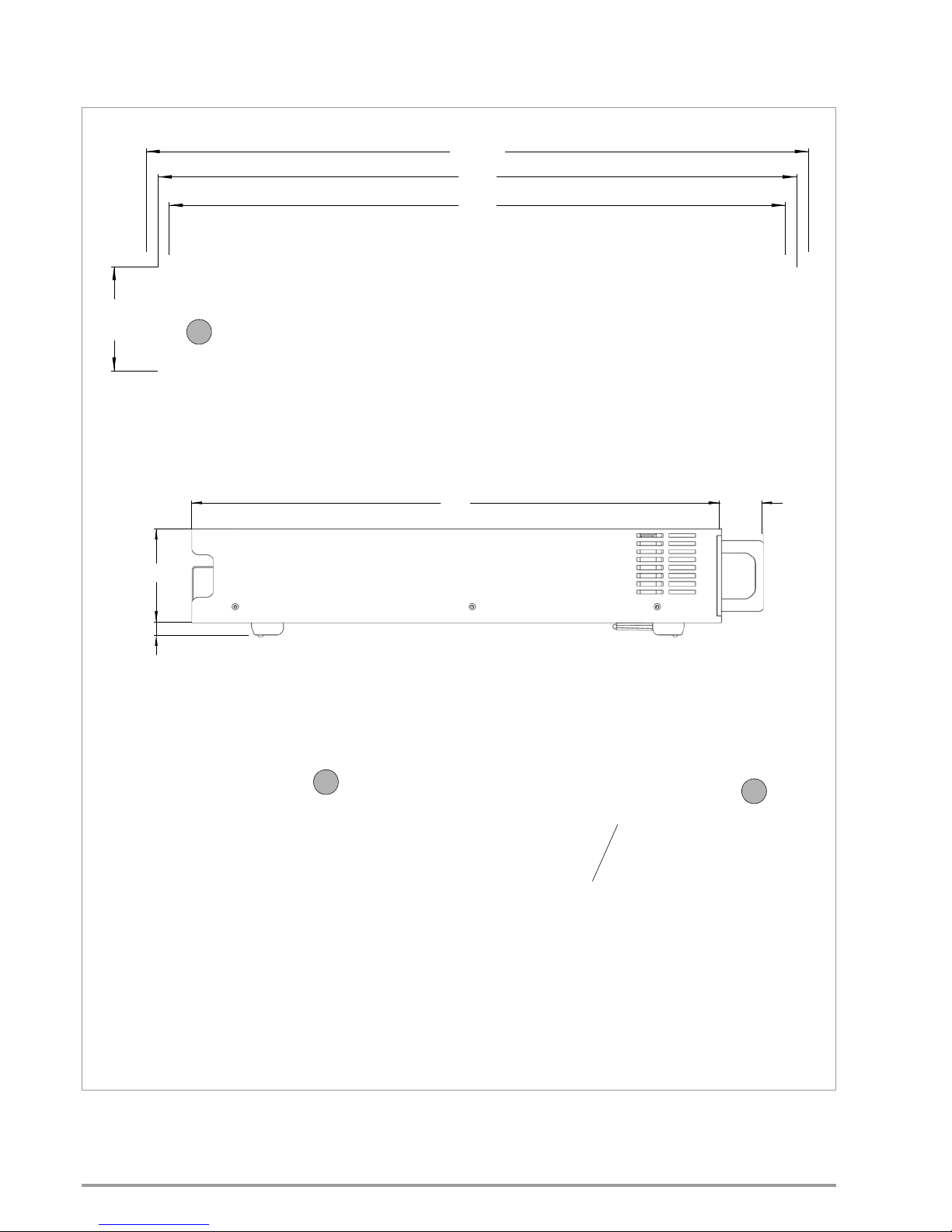
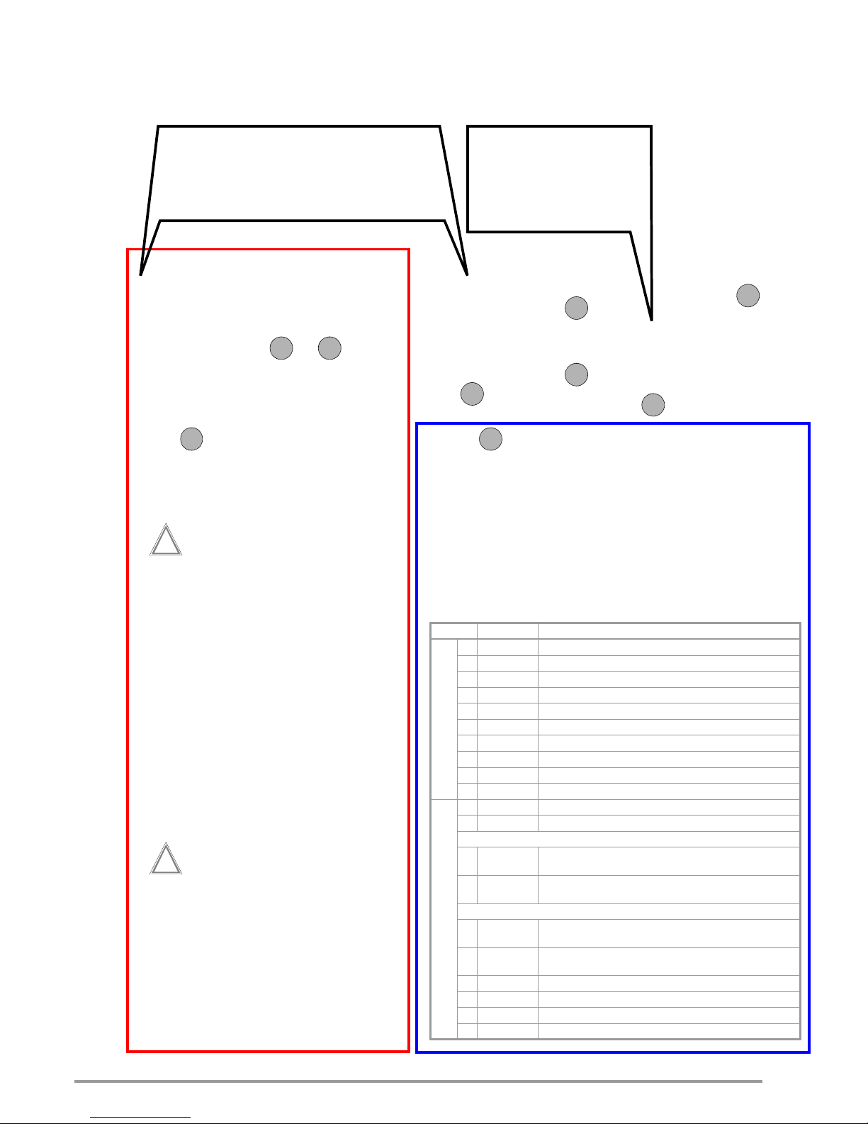
2.1 Dimensional Drawing SYSKON P500 / P800 / P1500
447
465
482.6
501
40
88
15
76.2
Installation position for optional IEEE-488 interface (material no. K384A).
All dimensions in mm
14
4
18
Page 5
GMC-I Messtechnik GmbH 5
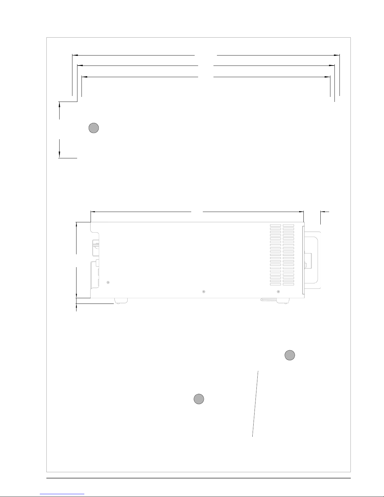
2.2 Dimensional Drawing SYSKON P3000 / P4500
447
465
482.6
501
40
177
14
101.6
Installation position for optional interface IEEE-488 (material no. K384A).
All dimensions in millimeter
14
4
18
Page 6
6 GMC-I Messtechnik GmbH
2.3 Preparing for Operation
Note: Numbers in brackets make reference to the items listed in
the dimensional drawing.
2.3.1 Installing the Optional GPIB Interface Module
Warning!
The device must be switched off when installing the
interface module. Remove the mains plug from the outlet.
The interface module may be damaged by electrostatic
discharge. ESDS handling guidelines must be adhered
to. Do not touch electrical contacts or components.
1. Unscrew the cover plate at the right-hand side of the rear
housing panel.
2. Carefully remove the ribbon cable from the cable uptake and
plug it in, being certain to observe coding as shown on the
interface module.
3. Carefully insert the connected module into the opening and
secure it with the previously removed cover plate screw.
2.3.2 Setup as Benchtop Device
The instrument is shipped as a benchtop device and the feet are
already installed. The mounting tabs for installation to a 19" rack
are shipped loose. The instrument can be set up as a benchtop
device and placed into operation. Unimpaired ventilation of the
instrument must be assured during setup.
2.3.3 Installation to a 19'' Device Cabinet
The SYSKON KONSTANTER housing allows for use as a benchtop instrument, as well as for installation to a 19'' rack.
The benchtop instrument can be quickly converted to a rack
mount device:
1. Unscrew the handles at the front.
2. Pull out the filler strips at the sides and replace them with the
included rack-mount fastening tabs.
3. Replace the front handles (if you prefer to leave the handles
off, turn M4 screws with a maximum length of 8 mm into the
threaded holes).
4. Unscrew the feet from the bottom of the housing.
5. Save all loose parts for possible future use.
Attention!
!
The instrument must be attached at both sides to guide
rails inside the device cabinet. The guide rails, as well as
the front panel mounting screws, are cabinet-specific
and must be procured from your rack supplier.
2.3.4 Connection to the Mains
Warning!
Protective Grounding, PE Connection
The KONSTANTER may only be placed into operation
after the protective conductor has been connected.
Interruption or disconnection of the protective conductor
may result in
danger for the user.
The device is connected to the mains by means of a 3
conductor cable with mains plug.
Attention!
!
Before switching the SYSKON KONSTANTER on, it must
be assured that available mains power complies with the
supply power values specified at the mains connection
on the back of the device.
SYSKON P500/P800/P1500: The device can be operated with either
115 or 230 V mains power. Full output power (1500 W) can be
taken advantage of when operated with 230 V mains power. Due
to resulting input current, only 750 W of output power can be
supplied when operated with 115 V mains power.
SYSKON P3000/P4500: In order to exploit the full nominal power, the
device must be operated with a 400 Volt 3-phase current system.
Integrated monitoring circuits detect mains power and limit output
power in the event of overloading.
The instrument is connected to a mains outlet with earthing contact via the mains inlet connector [18] at the rear panel with the
help of the included power cable (only included with the SYSKON
P500/P800/P1500).
2.3.5 Connecting Power Consumers
The output leads are connected to the output terminal blocks [14]
at the rear panel by means of ring-type cable lugs with the
included screws. (SYSKON P500/P800/P1500: M6 x 10, SYSKON
P3000/P4500: M8 x 12 and M6 x 10). In addition to this, 4 mm
holes are also provided which are intended for the connection of
any utilized measurement cables.
Connection:
Remove the safety cap.
Connect the output leads to the terminal blocks with the
provided screws and washers.
An adequate wire cross-section and correct polarity must be
assured. It is advisable to twist the output leads and to identify
polarity at both ends.
Avoid exerting excessive force at the terminals.
Align the leads to the openings in the safety cap.
Snap the safety cap back into place.
In order to be able to take advantage of highly constant output
voltage at the consumer even if long leads are used, sensing
leads can be used to compensate for voltage drops within the
output leads (see chapter 7).
The terminals for the sensing leads are located on the analog
interface.
2.3.6 Connection to Computer Interfaces
Three interfaces are available on the instrument for computercontrolled operation.
The device is furnished with a USB port and an RS 232 interface
as standard equipment.
A GPIB interface can be ordered as an optional module and
installed as described. Installation at a later point in time is also
possible.
The instrument cannot be remote controlled via more than one
interface at a time. It is thus advisable to connect the desired
interface only.
In order to avoid communications problems with the interfaces,
only one interface should be connected to the computer.
Problems may otherwise occur.
In order to assure that existing bus activity is not interfered with,
all affected devices should be switched off while establishing the
bus connection.
All of the interfaces have a common reference point (GND) which is
connected to PE, and are isolated from the output in accordance with the
specified electrical safety regulations.
Page 7
GMC-I Messtechnik GmbH 7
a) USB Port
The type B USB plug is at the at the bottom right-hand side of
the front panel. Appropriate USB drivers must be installed,
which are on the included CD or can be downloaded from the
Internet, see chapter 2.3.7.
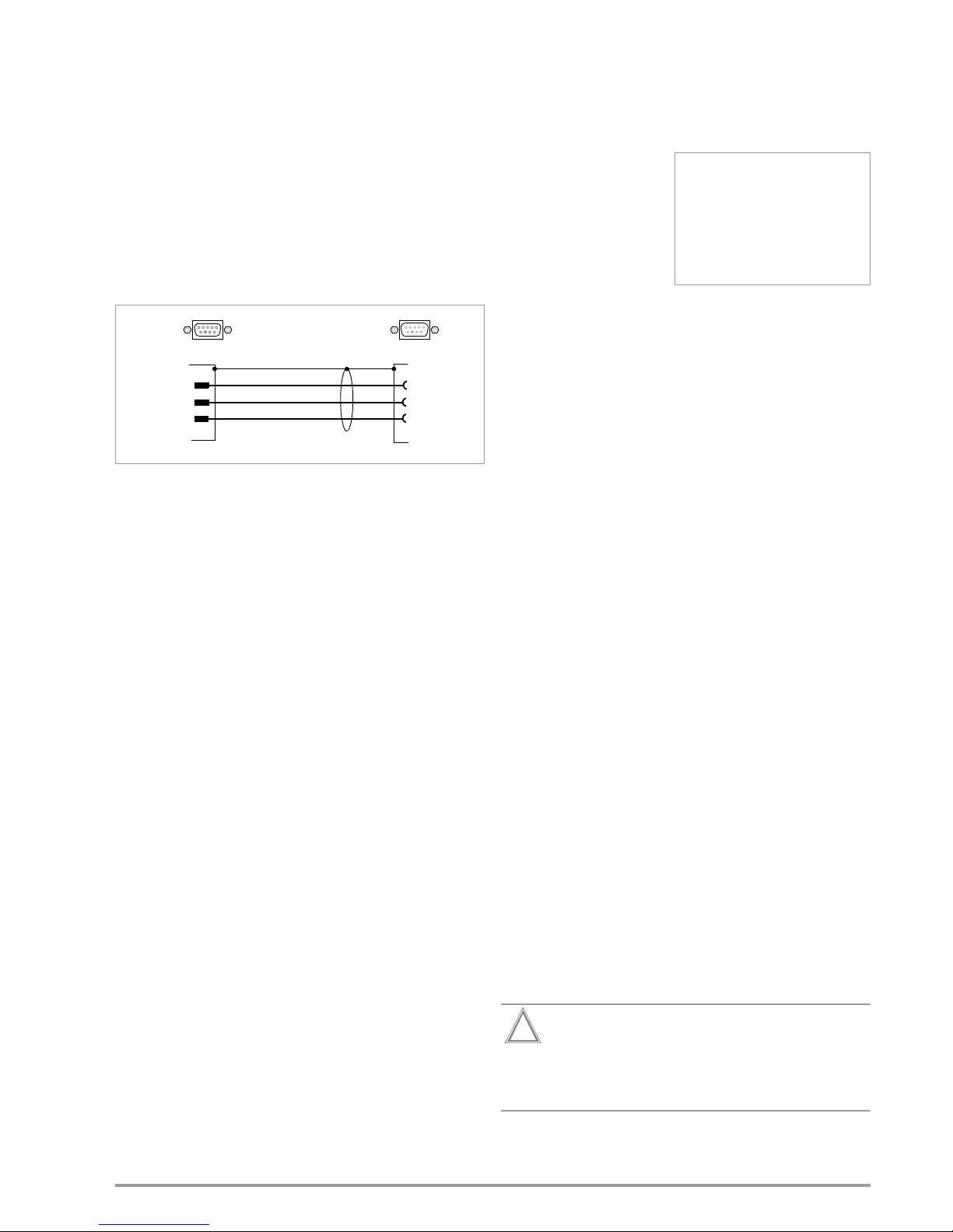
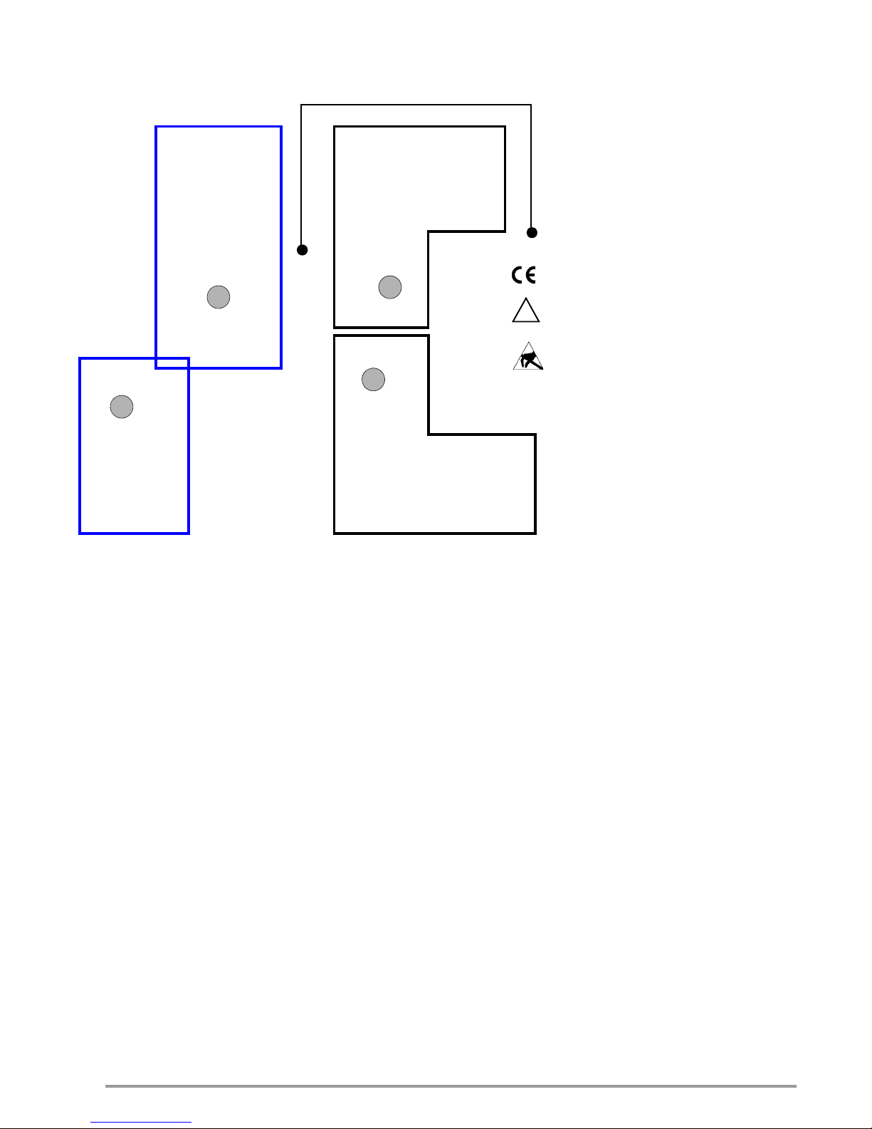
b) RS 232C Interface
The socket connector for the RS 232 interface is on the
instrument’s rear panel. A 9-pin subminiature socket connector is used to this end.
RS 232C Interface: 9-pin subminiature socket connector
DIN 41652
Connector pin assignments
Pin 2: TXD (transmit data)
Pin 3: RXD (receive data)
Pin 5: GND (ground)
Figure 1:Connector Cable for Serial Interface
c) GPIB or IEC Bus Interface (optional)
This interface is optional and can be installed to the slot
provided for this purpose on the rear panel.
IEEE 488/IEC 625 Interface Connection
24-pin IEEE 488 socket connector
IEEE 488/IEC 625 Interface Functions
SH1 – SOURCE HANDSHAKE
AH1 – ACCEPTOR HANDSHAKE
T6 – TALKER
L4 – LISTENER
TE0 No extended talker function
LE0 No extended listener function
SR1 – SERVICE REQUEST
RL1 – REMOTE / LOCAL
DC1 – DEVICE CLEAR
PP1 – PARALLEL POLL
DT1 – DEVICE TRIGGER
C0 – No controller function
E1 / 2 – Open collector driver
Codes / formats Per IEEE 488.2
2.3.7 Driver update (USB device driver)
We recommend a driver update in the following cases:
• Replacement purchases of devices
(connecting new devices of the SYSKON range with a PC)
• retrofitting of interface cards
• firmware udate
• software update
GMC-I Driver Control software can be downloaded from Gossen
Metrawatt's website at:
http://www.gossenmetrawatt.com
Produkte Software Software for Testers
Dienstprogramme Driver Control
The ZIP file can be unpacked in any desired directory. The setup
file then appears in the directory. Installation is started by double
clicking the setup file. A wizard guides you through the installation
procedure.
2.3.8 Connecting the Analog Interface
The plug connection for the
analog interface is located on
the rear panel. Two 10-pin
plug-in screw terminal connections are used to this
end. The necessary connections for the selected analog
control function can be made
here. In order to keep cross
interference with the analog
signals to a minimum, it is advisable to use shielded connector
cables. The individual signals are described under “Analog Interface”.
2.4 Switching the Device On
After the described preparations have been completed, the
device can be switched on. The mains switch is located at the
bottom left-hand side of the front panel.
Start-Up Routine
After switching the device on, the POWER lamp [4] lights up and
the fan is started. The microprocessor included in the device then
starts a power-up test. The following operations are performed
during the test routine (duration approximately 6 seconds):
• Reset all functional units (except battery-backed configuration
memory)
• LED and display segment test
• Hardware/firmware version display, see chapter 2.4.1
• Line voltage range is detected, see chapter 2.4.2
• Initialization of the 2 (possibly 3) computer interfaces; if the
device has been equipped with the optional “IEEE 488
interface”, the selected IEC bus device address then appears
briefly at the display (example: “Addr 12”).
See chapter 6 main menu level SETUP DISPLAY & INTERFACE for
changing the device address.
• Date display (internal clock)
• Time display (internal clock)
• Recall last settings if applicable
• Switch to (default after “*RST”) display of measured values for
voltage (Uout) and current (Iout)
After initial power-up, the device is set to its basic default
configuration (see the table entitled “Adjustable Functions and
Parameters” in chapter 10.1).
Upon shipment from the factory, the device is configured such
that the setpoints for output voltage and current are set to zero,
and the power output is set to off.
For further use, status after power on depends upon the selected
device configuration.
This configuration is selected either manually with the help of
the corresponding menu item, or by means of the POWER_ON
command.
Attention!
!
Avoid switching the device on and off in a rapid,
repeated fashion. This temporarily impairs the
effectiveness of the inrush current limiting function,
and may result in a blown fuse.
TxD 2
3
5
RxD
GND
2 RxD
3 TxD
5 GND
SYSKON
RS 232
PC / Controller
9-Pin Subminiature Socket Connector
9-Pin Subminiature Plug Connector
Page 8

8 GMC-I Messtechnik GmbH
2.4.1 Table of Firmware Versions
2.4.2 Response after Power ON with Varying Line Voltage
Ranges (230 V 115 V)
Up to and including Firmware Version 004
After „Power ON“, a distinction is made - on the basis of the line
voltage detected - between the two available power ranges.
When the line voltage is „low“, output power Pnom is reduced by
half (see chapter 4.1).
The specified value „PSET < Pnom“ (and/or „PSET < Pnenn/2“ in
the case of power derating), in turn, is the setting criterion for the
function „Power control“. After an automatic change of Pnom it
may be necessary to correct the PSET value for power control!
Power ON & Setting „Power_ON RST / SBY / RCL / ...“:
• „RST“ Pnom is always readjusted in accordance
with the detected line voltage.
• „SBY“, „RCL“ A low line voltage always leads to a reduced
Pnom value. If the device is subsequently
switched on to a „high“ line voltage, the low
Pnom value remains active until either:
– a „RESET“ is performed (!)
or
– „Power“ is reconnected with parameter
setting
„POWER_ON RST“
.
Changes between the line voltage ranges result in system messsages, see Err AC-L and Err AC-H in chapter 11.
As from Firmware-Version 005
After „Power ON“, a distinction is made - on the basis of the line
voltage detected - between the two available power ranges.
When the line voltage is „low“, output power is limited to approximately 55 % of the nominal power.
If the device is switched on in setting „POWER_ON RST“ at „low“
line voltage, the setting limit value is reduced to half the nominal
power for parameter PSET.
The specified value „PSET < Pnom“ (and/or „PSET < Pnenn/2“ in
the case of power derating), in turn, is the setting criterion for the
function „Power control“.
Power ON & Setting „Power_ON RST / SBY / RCL / ...“:
• „RST“ Pnom is always readjusted in accordance
with the detected line voltage.
• „SBY“, „RCL“ A low line voltage always leads to a reduced
maximum output power. The setting limit
values for parameter PSET, however, remain
unchanged until either:
– a memory recall of a corresponding device
setting is performed
or
– „Power“ is reconnected with parameter
setting
„POWER_ON RST“
.
Changes between the line voltage ranges result in system messsages, see Err AC-L and Err AC-H in chapter 11.
Firmware Version Memory Locations
Version 003 12 SETUP memory locations
1536 SEQUENCE memory locations
Version 004 15 SETUP memory locations
1700 SEQUENCE memory locations
Page 9

GMC-I Messtechnik GmbH 9
3 Technical Description
Description
SYSKON KONSTANTERs (power factor control, single-output
system power supplies) are manual and remote controllable DC
power supplies for laboratory and system use. Thanks to modern
switching controller technology, the devices are compact and
lightweight despite high output power.
Active power factor control assures nearly sinusoidal mains input
current.
The floating output features “safety separation” from the mains
input as well as from the computer interfaces, and is classified as
a safety extra-low voltage circuit (SELV) in accordance with VDE /
IEC. Wide ranging nominal output power values are available from
output voltage and output current.
The power output is voltage and current controlled with limiting to
maximum withdrawable power.
Transition to the control modes is automatic in accordance with
the selected setpoints and load circumstances.
The control loops are designed for short response times.
An automatically activated, dynamic sink (can be disabled)
provides for quick discharging of the output capacitors.
Numerous protective functions and monitoring devices allow for
ideal adaptation to actual conditions of use.
Features
The devices are generally equipped with a control panel and
display, as well as an analog interface.
One USB port and one RS 232 interface are provided as standard
equipment for integration into computer controlled systems. The
drivers for the USB port are provided as accessories on the
included CD ROM.
An IEEE 488 interface can be additionally installed to the device
from the outside ,or retrofitted as an option.
Manual adjustment of voltage and current is accomplished by
means of two rotary encoders with selectable resolution, or with
the numeric keypad. Numerous additional functions can be
accessed via keys.
Two 5-place digital LED displays read out measured values and
settings. LEDs indicate the current operating mode, selected display parameters and the status of device and interface functions.
The analog interface makes it possible to adjust output voltage
and current with the help of external control voltages. Monitor
outputs read out an analog image of the voltage and current
output quantities for further processing or additional displays.
These control inputs and monitor outputs can also be used to
couple several devices for master-slave operation with parallel or
series connection.
Two floating trigger inputs are available for controlling certain
device functions. For example, they can be used to switch the
output on and off, or to control sequences.
Furthermore, three signal outputs are included at the analog interface, two of which are floating. These can be activated depending
upon various functions, and can thus be used to control external
devices or sequences.
Applications Range
Konstanters are suitable for use wherever electronic modules with
controlled direct voltage or controlled current need to be supplied
with electrical power, especially in the fields of R&D, testing,
production, test systems and training.
Thanks to their characteristic U-I-P curve, the devices have a
broad working range, making it possible to cover a large range of
applications with a single device.
Due to their short response times, SYSKON KONSTANTERs can
be used for replication and simulation of onboard electrical systems, for example in automotive applications. Test signals specified in the corresponding standards can be generated. The fact
that these voltage-current-time profiles can be saved to memory
at the Konstanter for running independent sequences is highly
advantageous. When used in test systems, it is thus possible to
significantly reduce workload for the control computer. Further
functions for test applications of this sort include the Min-Max
function for acquiring extreme values and the tolerance band
function which generates a signal when measured values do not
lie within the specified tolerance limits.
The Konstanter thus serves as an autonomous test system for
many applications.
Adjustable Functions (selection)
– Voltage and current setpoint values
– Voltage and current limit values (soft-limits)
– Activate / deactivate the output
– Overvoltage protection trigger value (OVP)
– Overcurrent protection trigger value (OCP)
– Delay time for reaction to overvoltage
– Selection of the desired reaction when OVP and OCP are
triggered
– Delay time for reaction to overcurrent
– Performance after power on
– Reset device settings
– Save device settings
– Recall device settings, individually or sequentially
– Function selection for trigger input
– Configurable status and events management
with enabling windows (via computer interface)
– Activate / deactivate digital displays
Retrievable Information (selection)
– Presently measured voltage and current values
– Minimum and maximum measured voltage and current values
– Current output power
– Current device settings
– Current device status (i.e. control mode, overtemperature etc.)
– Occurred events (i.e. mains failure, overtemperature,
overvoltage, overload etc.)
– Device ID (via computer interface)
Protection and Additional Functions
– Sensor terminals protected against polarity reversal and
automatic switching to auto-sensing
– Protection against excessive temperature
– Output protected against reverse polarity
– Front panel control disabling
– Backup battery for device settings memory
– Recognition of mains or phase failure
– Inrush current limiting
Page 10

10 GMC-I Messtechnik GmbH
Performance After Power on
In the event of mains failure, it’s important to specify which
operating state the device will assume when power is restored.
This may be extremely important if the device is used in long-term
testing applications.
One of the following states can be selected:
– Reset = default setting (0 V, 0 A, output deactivated)
– Standby= last used configuration but with deactivated output
– Recall =
last used configuration – same as when the instrument
was last switched off, with
active output if it was active prior to
mains failure
– Recall a device configuration from setup memory
Set Output Voltage and Output Current
Output voltage and output current can also be adjusted using the
rotary encoders or the numeric keypad if desired. The rotary
encoders are used exclusively for adjusting voltage and current.
The decimal place to be changed is selected with the scroll keys.
Additional functions and parameters can be accessed and
adjusted with the keys.
Switching the Input On and Off
The power output can be switched on and off by pressing the
appropriate key, with a computer command or by applying a
signal to the trigger input. When switched off, the output is highly
resistive and is not electrically isolated from the power consumer.
The LED on the key indicates status.
Protection and Additional Functions
A multitude of protection and additional functions have been
integrated, for example:
• Limiting of the setting ranges for voltage and current
• Overvoltage protection (OVP) with adjustable response delay
and reaction
• Overcurrent protection (OCP) with adjustable response delay
and reaction
• Protection in the event of reversed polarity at the sensing leads
• Automatic switching to auto-sensing
• Protection against excessive temperature
• Output protected against reverse polarity
• Front panel control disabling
• Backup battery for device settings memory
• Mains failure detection
• Inrush current limiting
• Line voltage monitoring
Line Voltage Monitoring
To protect the device, power output is deactivated and disabled
in the event of voltage dips or short-term interruptions. The device
must be restarted with „Power ON“.
Dynamic Sink
A dynamic sink is activated by the control loops as required for
rapid discharging of the output capacitors.
This allows for short response times when switching to smaller
setpoint values. Depending upon the application, the sink
function can also be disabled.
Auto-Sensing
The device can be switched to sensing mode operation (remote
sensing) in order to compensate for voltage drop at the output
leads. Sensing lead terminals are available to this end at the
analog interface. If the (–) negative sensing terminal is connected
to the negative load point, the device is automatically switched to
sensing mode operation. Maximum compensatable voltage drop
is 1 V per output lead.
Front Panel Control Disabling
The controls can be disabled to prevent unauthorized operation
by pressing the appropriate key, with a computer command or by
applying a signal to the trigger input.
Analog Control Inputs
Voltage and current can also be adjusted by via the control inputs
at the analog interface. A 5 V signal corresponds to 100% of the
respective nominal value.
These inputs can be switched on and off using the keys, or with
computer commands.
The controlled output quantity is the sum of the digital setpoint
value and the specified value at the control input.
This function makes it possible to superimpose these control
signals onto the output quantities.
Monitor Outputs
The actual values for output voltage and current can be
acquired at the monitor outputs as a standardized signal (10 V
corresponds to 100% nominal value).
Trigger Inputs
Two floating trigger inputs are available for controlling device
functions. The following trigger input assignments can be
selected:
– output = Switch the power output on and off
– local lock = Disable controls
– SQS = (sequence step) Step-by-step control of a
stored sequence
– sequence = Start / stop the sequence function
– Analog input = Activate / deactivate the analog control inputs
Signal Outputs
Programmable Control Outputs
The analog interface is equipped with three digital control outputs
for status messages to external monitoring devices, for switching
external components on and off, or for coupling purposes.
The status of these outputs can be defined either directly, or
depending upon the following device statuses:
– Output on or off
– Voltage or current regulation
– Sequence function running or finished
– SSET signal status for the sequence function
– Limit value message for the measuring function (tolerance band)
Min-Max Measured Value Memory
The Min-Max function automatically acquires and saves minimum
and maximum voltage and current values.
Tolerance Band (in combination with Min-Max function)
Measured output values can be continuously compared with
stored upper and lower tolerance band values. Evaluation is
possible via the programmable control outputs.
Page 11
GMC-I Messtechnik GmbH 11
Memory
The memory function makes it possible to save and recall device
configurations using a battery-backed memory module.
The memory module is equipped with two storage areas:
– Setup memory: 12/15 memory locations for complete
configurations
– Sequence memory: 1536/1700 memory locations for the fol-
lowing sequence parameters: voltage setpoint USET, current
setpoint ISET, dwell time TSET and function request FSET,
with the ability to invoke subsequences
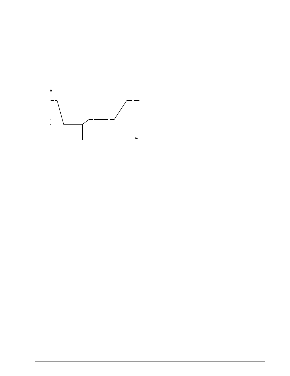
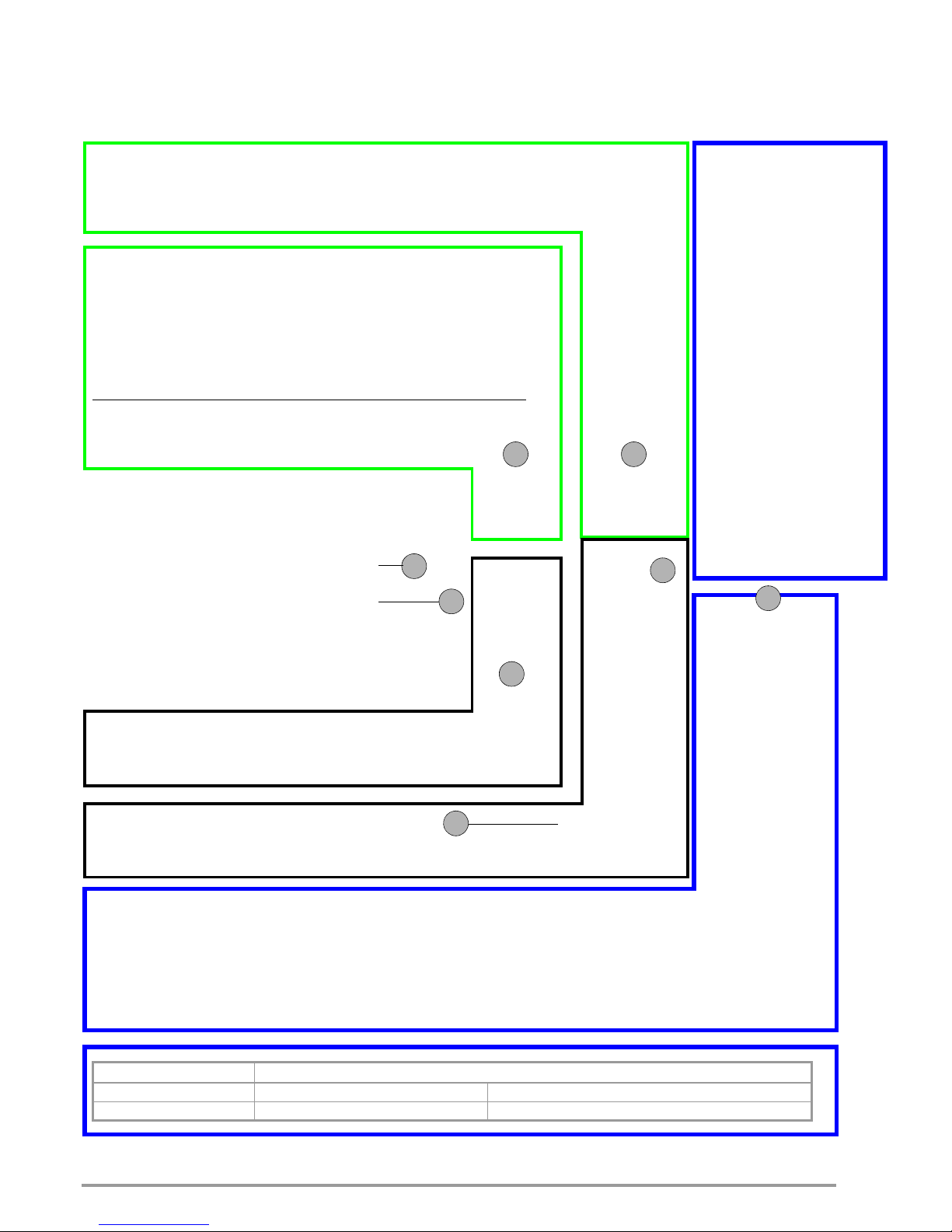
Sample Application
Generation of a characteristic voltage curve in an automotive electrical system when starting the engine
Note:
The drop times can be influenced by the input impedance of the
DUT.
Balancing Function (adjust)
Offset and final values for setting and measured values for output
quantities voltage and current are balanced digitally in the device.
The user can execute balancing as required with this function.
DAkkS Calibration Certificate
All SYSKON Konstanters are shipped with a DAkkS calibration
certificate issued by our DAkkS test laboratory.
U [V]
12
6
4.5
5
t [ms]
15 5 2000 10
Page 12

12 GMC-I Messtechnik GmbH
4 Technical Data
4.1 General Data
Output Operating Ranges, Characteristic U-I-P Curve SYSKON P500
Output Operating Ranges, Characteristic U-I-P Curve SYSKON P800
Output Operating Ranges, Characteristic U-I-P Curve SYSKON P1500
Output Operating Ranges, Characteristic U-I-P Curve SYSKON P3000
Output Operating Ranges, Characteristic U-I-P Curve SYSKON P4500
Output
Regulator type Primary switched-mode regulator
Operating modes Adjustable constant voltage / constant cur-
rent source with automatic sharp transition
Output insulation Floating output with “safe electrical
separation” from the mains input and
computer interfaces
Allowable potential,
output–ground Max. 240 V DC
Capacitance, output–ground (housing)
SYSKON P500
typically 1000 nF
SYSKON P800
typically 1000 nF
SYSKON P1500 typically 1000 nF
SYSKON P3000 typically 1000 nF
SYSKON P4500 typically 1000 nF
Page 13

GMC-I Messtechnik GmbH 13
Analog Interface
Functions – Auto-sensing mode
– 2 programmable trigger inputs
– 3 programmable signal outputs
– Voltage control input (0 ... 5 V)
– Current control input (0 ... 5 V)
– Voltage monitor output (0 ... 10 V)
– Current monitor output (0 ... 10 V)
– Master-slave parallel operation
– Master-slave series operation
– Auxiliary power output: 15 V / 60 mA
Computer Interfaces
• IEC-625 / IEEE 488 interface (optional)
• RS 232 interface
Transmission mode asynchronous
Transmission speed 1200 to 115,200 baud, adjustable
•USB port
USB port: 4-pin, type B
USB 1.1 compatible with USB 2.0
Connector pin assignments 1: VCC, 2: D-, 3: D+, 4: GND
Transmission speed 9600 to 115,200 baud, adjustable
Power supply
Line voltage
115
/230 V ~ + 10 / – 15%; 47 to 63 Hz
Inrush current Max. 50 A
S
Mains fuse
SYSKON P500/P800/P1500
:
1 x M 15 A / 250 V (6.3 x 32 mm), UL
SYSKON P3000
/4500: 3 x M15 A/250 V
Electrical Safety
Safety class I
Measuring category II for mains input
I for output and interfaces
Fouling factor 2
Earth leakage current < 2.5 mA
RMS
Electrical isolation Test voltage
Output – mains 2.2 kV ~
Output – bus/ground 1.4 kV ~
Mains – bus/ground 2.2 kV –
Bus – ground No electrical isolation
Applicated Standards
IEC 61010-1:2010
DIN EN 61010-1:2010
VDE 0411-1:2011
EN 61326
4.1.1 Electromagnetic Compatibility
SYSKON P500/P800/P1500
Generic standard EN 61326-1: October 2006
Interference emission EN 55022: class B
Interference immunity
EN 61000-4-2: feature A
EN 61000-4-3: feature B
EN 61000-4-4: feature A
EN 61000-4-5: feature A
EN 61000-4-6: feature A
EN 61000-4-8: feature A
EN 61000-4-11: feature A
SYSKON P3000/4500
Generic standard EN 61326-1: October 2006
Interference emission EN 55022: class A *
Interference immunity EN 61000-4-2: feature B
EN 61000-4-3: feature A
EN 61000-4-4: feature B
EN 61000-4-5: feature B
EN 61000-4-6: feature A
EN 61000-4-8: feature A
EN 61000-4-11: feature B
* Note:
Approved for the deployment in industrial environment. The
device may cause radio interferences in domestic areas.
4.1.2 Ambient Conditions
Temperature range Operation: 0 to 40° C
Storage: –25 to +75° C
Atmospheric
humidity Operation: 75% rel. humidity,
no condensation allowed
Storage: 65% rel. humidity
Cooling With integrated fan
(temperature controlled)
Inlet vent: Side panel
Outlet vent: Rear panel
Operating noise Noise pressure level at a distance of 30 cm
with fan set to low / high
Front 17 / 28 dBA
Rear 22 / 32 dBA
Left 17 / 28 dBA
Right 20 / 31 dBA
Page 14

14 GMC-I Messtechnik GmbH
4.2 Mechanical Data
Protection IP 00 for device and interface connections
IP 20 for housing
Table Excerpt Regarding Significance of IP Codes
Design Benchtop device, suitable for installation to 19" cabinets
HE = standard height units
4.2.1 Terminals (rear panel)
Mains input
SYSKON P1500
:
10 A IEC inlet plug with earthing
contact (L + N + PE)
SYSKON P3000
/4500:
Connection terminals
(min. 16 A)
(L1 + L2 + L3 + N + PE)
Output
SYSKON P1500
:
Terminal blocks with thread for
M6 screws and 4 mm dia. holes
SYSKON P3000
/4500:
Terminal blocks with thread for M8 and M6
screws and 4 mm dia. holes
Analog interface / Double-row plug connector
sensing leads with two 10-pole screw terminals
IP XY
(1
st
char. X)
Protection against penetration by solid particles
IP XY
(2nd char. Y)
Protection against
penetration by water
0 Not protected 0 Not protected
1 50.0 mm dia.
1 Vertical dripping
2 12.5 mm dia.
2 Dripping (15 inclination)
Article No. Designation Dimensions (W x H x D) Weight
K346A SYSKON
P500-060-030
19" x 2 HE
447 x 102 (88) x 541 (501) mm
10 kg
K347A SYSKON
P800-060-040
19" x 2 HE
447 x 102 (88) x 541 (501) mm
10 kg
K353A SYSKON
P1500-060-060
19" x 2 HE
447 x 102 (88) x 541 (501) mm
10 kg
K363A SYSKON
P3000-060-120
19" x 4 HE
447 x 191 (177) x 541 (501) mm
16 kg
K364A SYSKON
P4500-060-180
19" x 4 HE
447 x 191 (177) x 541 (501) mm
20 kg
K384A IEEE 488 interface
(optional)
Approx. 0.14 kg
Page 15

GMC-I Messtechnik GmbH 15
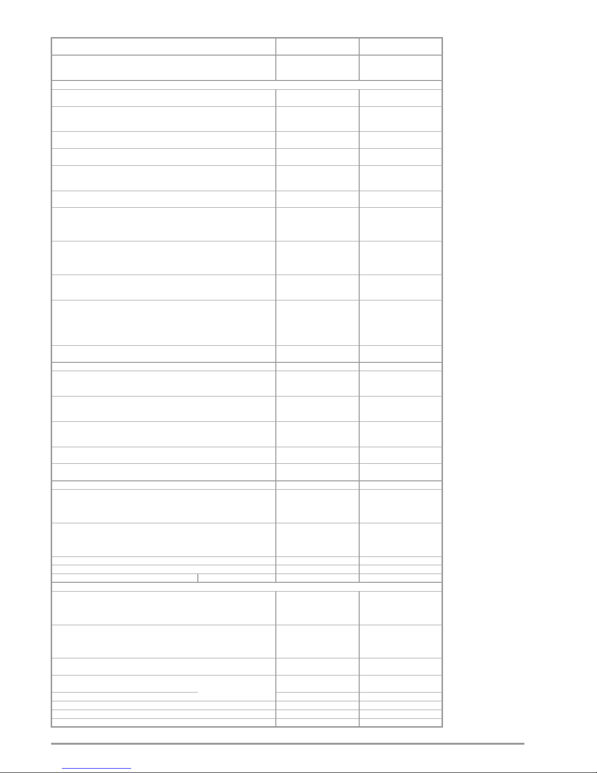
4.3 Electrical Data
1)
at maximum current setting not including processing time for the previous voltage setting command
2)
Nominal load: Rload = Uset² / Pnom
Article Number K346A K347A K353A
Type SYSKON P500-060-030 SYSKON P800-060-040 SYSKON P1500-060-060
Nominal Output Data Voltage setting range
Current setting range
Powe r
0 ... 60 V
0 ... 30 A
max. 500 W
0 ... 60 V
0 ... 40 A
max. 800 W
0 to 60 V
0 to 60 A
Max. 1500 W
Output Characteristics (ppm and percentage values make reference to the respective setting or measured value)
Setting resolution Voltage
Current
1 mV
1 mA
1 mV
1 mA
1 mV
1 mA
Setting accuracy (at 23 5 °C) Auto-sensing mode
Without auto-sensing
Voltage
Current
0.05 % + 30 mV
0.05 % + 48 mV
0.05 % + 90 mA
0.05 % + 30 mV
0.05 % + 48 mV
0.05 % + 90 mA
0.05% + 30 mV
0.05% + 48 mV
0.05% + 90 mA
Temperature coefficient
for / K setting
Voltage
Current
100 ppm
100 ppm
100 ppm
100 ppm
100 ppm
100 ppm
Setting accuracy via analog interface (at 23 5°C)
U
setnom/Usetanalog
= 12; I
setnom/Isetanalog
= 12/24/36
Voltage
Current
0.6 % + 120 mV
0.6 % + 120 mA
0.6 % + 120 mV
0.6 % + 120 mA
0.6% + 120 mV
1.2% + 120 mA
Static system deviation Auto-sensing mode
at 100% load fluctuation
Without auto-sensing
Voltage
Current
30 mV (< 500 μV/A)
48 mV
(< 800 μV/A;)
30 mA
(< 500 μA/V)
30 mV (< 500 μV/A)
48 mV
(< 800 μV/A;)
30 mA
(< 500 μA/V)
30 mV (< 500 μV/A)
48 mV
(< 800 μV/A;)
30 mA
(< 500 μA/V)
Static system deviation
with 10% line voltage fluctuation
Voltage
Current
5 mV
5 mA
5 mV
5 mA
5 mV
5 mA
Residual ripple Voltage
Current
Ripple: 10 Hz to 20 kHz
Ripple: 10 Hz to 1 MHz
Ripple + noise: 10 Hz to 10 MHz
Ripple + noise: 10 Hz to 10 MHz
40 mV
ss
50 mV
ss
60 mVss / 6 mV
eff
50 mA
eff
40 mV
ss
50 mV
ss
60 mVss / 6 mV
eff
50 mA
eff
40 mV
ss
50 mV
ss
60 mVss / 6 mV
RMS
50 mA
RMS
Output voltage transient recovery time with sudden
load variation within range of 20 to 100% I
nom
and 20 to 100% U
nom
Tol e ra nc e
I = 10%
I = + 80% + approx. 800 A/ms
I = – 80 % + approx. 1200 A/ms
120 mV
100 μs
600 μs
950 μs
120 mV
100 μs
500 μs
650 μs
120 mV
100 μs
400 μs
500 μs
Output voltage over and undershooting with sudden
load variation within a range of 20 to 100% I
nom
and 20 to 100% U
nom
I = 10%
I = 80%
150 mV
500 mV
150 mV
550 mV
150 mV
700 mV
Setting time for output voltage
1)
where Uset step = 0 V 60 V
where Uset step = 60 V 1 V
where Uset step = 0 V 25 V
where Uset step = 25 V 1 V
Tol e ra nc e
No-load; nominal load
2)
No-load; nominal load
2)
No-load; nominal load
2)
No-load; nominal load
2)
120 mV
2 ms / 2 ms
70 ms / 20 ms
1.4 ms / 1.4 ms
16 ms / 5 ms
120 mV
2 ms / 2 ms
70 ms / 15 ms
1.4 ms / 1.4 ms
16 ms / 3 ms
120 mV
2 ms / 2 ms
70 ms / 11ms
1.4 ms / 1.4 ms
16 ms / 3 ms
Output capacitor
Sink (continuous power)
Nominal value
Power
2020 μF
40 W – 65 W
2020 μF
40 W – 65 W
2020 μF
40 to 65 W
Measuring Function
Measuring Range Voltage
Current
Power
– 16.384 … + 98.300 V
– 32.766 … + 98.300 A
U x I
– 16.384 … + 98.300 V
– 32.766 … + 98.300 A
U x I
– 16.384 to + 98.300 V
– 2.766 to + 98.300 A
U x I
Measuring resolution Voltage
Current
Power
2 mV
2 mA
100 mW
2 mV
2 mA
100 mW
2 mV
2 mA
100 mW
Measuring accuracy (at 23 5°C) Voltage
Current
Power
0.05 % + 30 mV
0.4 % + 90 mA
0.5 % + 1 W
0.05 % + 30 mV
0.4 % + 90 mA
0.5 % + 1 W
0.05% + 30 mV
0.4% + 90 mA
0.5% + 1 W
Measured value temperature coefficient / K Voltage
Current
50 ppm + 0.4 mV
100 ppm + 1 mA
50 ppm + 0.4 mV
100 ppm + 1 mA
0.4 mV + 50 ppm
1 mA + 100 ppm
Measuring accuracy (at 23 ± 5 °C) at analog interface
U
actualnom
/ U
actualanalog
= 6; I
actualnom
/ I
actualanalog
= 6/12/18
Voltage
Current
0.4 % + 120 mV
0.5 % + 180 mA
0.4 % + 120 mV
0.5 % + 180 mA
0.4 % + 120 mV
1.2 % + 180 mA
Protection and Additional Functions
Output overvoltage protection Trigger value
Response time
Setting Range
Setting resolution
Setting accuracy
3 … 80 V
20 mV
150 mV –10 m x I
a
200 μs
3 … 80 V
20 mV
150 mV –20 m x I
a
200 μs
3 to 80 V
20 mV
150 mV – 10 m x I
a
200 μs
Output overcurrent protection Trigger value
Response time
Setting Range
Setting resolution
Setting accuracy
1.5 … 40 A
20 mA
–(1% + 350 mA) – 20 mA/V x U
a
200 μs
2 … 53 A
20 mA
–
(1% + 350 mA) – 20 mA/V x U
a
200 μs
3 to 80 A
20 mA
–(1% + 350 mA) – 20 mA/V x U
a
200 μs
Reverse polarity protection load capacity Continuous 30 A 40 A 60 A
Reverse voltage withstand capacity Continuous 70 V – 70 V – 70 V –
Auto-sensing mode Compensatable voltage drop Per output lead 1 V 1 V 1 V
General
Power supply with 230 V~ nominal line voltage
Power consumption
Line voltage
At nominal load, 100%
At no load
230 V~ + 10 / – 15 %,
47 … 63 Hz
700 VA; 650 W
96 VA; 37 W
230 V~ + 10 / – 15 %,
47 … 63 Hz
1050 VA; 1000 W
96 VA; 37 W
230 V~ + 10 / – 15%,
47 to 63 Hz
1925 VA; 1865 W
96 VA; 37 W
Power supply with 115 V~ nominal line voltage
Power consumption
Line voltage
At nominal load, 50%
At no load
115 V~ + 10 / – 15 %,
47 … 63 Hz
800 VA; 750 W
55 VA; 36 W
115 V~ + 10 / – 15 %,
47 … 63 Hz
1175 VA; 1150 W
55 VA; 36 W
115 V~ + 10 / – 15%,
47 to 63 Hz
1125 VA; 1100 W
55 VA; 36 W
Max. power loss
At a nominal load
500 W/800 W/1500 W (230 V~)
At a nominal load 500 W/800 W/750 W (115 V~)
150 W
250 W
200 W
350 W
365 W
350 W
Efficiency
At a nominal load
500 W/800 W/1500 W (230 V~)
At a nominal load 500 W/800 W/750 W (115 V~)
77 %
66 %
80 %
70 %
80%
68%
Switching frequency, PFC / DC/DC Typical 47 kHz / 230 kHz 47 kHz / 230 kHz 47 kHz / 230 kHz
Inrush current Max. 50 A
s
50 A
s
50 A
s
Mains fuse (6.3 x 32 mm, UL) 1 x M 15 A / 250 V 1 x M 15 A / 250 V 1 x M 15 A / 250 V
MTBF (mean time between failures) at 40 °C > 50,000 h > 50,000 h > 50,000 hours
Page 16
16 GMC-I Messtechnik GmbH
1)
at maximum current setting not including processing time for the previous voltage setting command
2)
Nominal load: Rload = Uset² / Pnom
Article Number K363A K364A
Type SYSKON P3000-060-120 SYSKON P4500-060-180
Nominal Output Data Voltage setting range
Current setting range
Power
0 ... 60 V
0 ... 120 A
max. 3000 W
0 ... 60 V
0 ... 180 A
max. 4500 W
Output Characteristics (ppm and percentage values make reference to the respective setting or measured value)
Setting resolution Voltage
Current
1 mV
2 mA
1 mV
3.125 mA
Setting accuracy (at 23 5 °C) Auto-sensing mode
Without auto-sensing
Voltage
Current
0.07 % + 48 mV
0.07 % + 60 mV
0.1 % + 135 mA
0.1 % + 48 mV
0.1 % + 60 mV
0.15 % + 180 mA
Temperature coefficient
for / K setting
Voltage
Current
100 ppm
100 ppm
100 ppm
100 ppm
Setting accuracy via analog interface (at 23 5°C)
U
setnom/Usetanalog
= 12; I
setnom/Isetanalog
= 12/24/36
Voltage
Current
0.6 % + 150 mV
1.2 % + 180 mA
0.6 % + 150 mV
1.2 % + 240 mA
Static system deviation Auto-sensing mode
at 100% load fluctuation
Without auto-sensing
Voltage
Current
60 mV (< 500 μV/A)
96 mV (< 800 μV/A)
60 mA (< 1000 μA/V)
90 mV (< 500 μV/A)
144 mV (< 800 μV/A)
90 mA (< 1500 μA/V)
Static system deviation
with 10% line voltage fluctuation
Voltage
Current
7 mV
30 mA
10 mV
60 mA
Residual ripple Voltage
Current
Ripple: 10 Hz to 20 kHz
Ripple: 10 Hz to 1 MHz
Ripple + noise: 10 Hz to 10 MHz
Ripple + noise: 10 Hz to 10 MHz
60 mV
ss
75 mV
ss
90 mVss / 10 mV
eff
70 mA
eff
80 mV
ss
100 mV
ss
120 mVss / 15 mV
eff
100 mA
eff
Output voltage transient recovery time with sudden
load variation within range of 20 to 100% I
nom
and 20 to 100% U
nom
Tol e ra nc e
I = 10%
I = + 80% + approx. 800 A/ms
I = – 80 % + approx. 1200 A/ms
120 mV
400 μs
1200 μs
1900 μs
120 mV
500 μs
1600 μs
2500 μs
Output voltage over and undershooting with sudden
load variation within a range of 20 to 100% I
nom
and 20 to 100% U
nom
I = 10%
I = 80%
200 mV
1200 mV
250 mV
1300 mV
Setting time for output voltage
1)
where Uset step = 0 V 60 V
where Uset step = 60 V 1 V
where Uset step = 0 V 25 V
where Uset step = 25 V 1 V
Tol e ra nc e
No-load; nominal load
2)
No-load; nominal load
2)
No-load; nominal load
2)
No-load; nominal load
2)
120 mV
4 ms / 15 ms
70 ms / 11 ms
1.2 ms / 6 ms
16 ms / 6 ms
120 mV
7 ms / 19 ms
70 ms / 11 ms
2.4 ms / 11 ms
16 ms / 6 ms
Output capacitor
Sink (continuous power)
Nominal value
Power
4040 μF
80 W – 130 W
6060 μF
120 W – 195 W
Measuring Function
Measuring Range Voltage
Current
Power
– 16.384 … + 98.300 V
– 65.532 … + 196.600 A
U x I
– 16.384 … + 98.300 V
– 98.298 … + 294.900 A
U x I
Measuring resolution Voltage
Current
Power
2 mV
4 mA
100 mW
2 mV
6 mA
100 mW
Measuring accuracy (at 23 5°C) Voltage
Current
Power
0.07 % + 48 mV
0.6 % + 120 mA
0.7 % + 2 W
0.1 % + 48 mV
0.8 % + 180 mA
1 % + 3 W
Measured value temperature coefficient / K Voltage
Current
50 ppm + 0.6 mV
100 ppm + 2 mA
50 ppm + 0.8 mV
100 ppm + 3 mA
Measuring accuracy (at 23 ± 5 °C) at analog interface
U
actualnom
/ U
actualanalog
= 6; I
actualnom
/ I
actualanalog
= 6/12/18
Voltage
Current
0.6 % + 180 mV
1.2 % + 240 mA
0.8 % + 180 mV
1.2 % + 300 mA
Protection and Additional Functions
Output overvoltage protection Trigger value
Response time
Setting Range
Setting resolution
Setting accuracy
3 … 80 V
20 mV
150 mV – 20 m x I
a
200 μs
3 … 80 V
20 mV
150 mV –20 m x I
a
200 μs
Output overcurrent protection Trigger value
Response time
Setting Range
Setting resolution
Setting accuracy
6 … 160 A
50 mA
–
(1% + 500 mA) – 40 mA/V x U
a
200 μs
9 … 240 A
100 mA
–
(1% + 700 mA) – 60 mA/V x Ua
200 μs
Reverse polarity protection load capacity Continuous 120 A 180 A
Reverse voltage withstand capacity Continuous 70 V – 70 V –
Auto-sensing mode Compensatable voltage drop Per output lead 1 V 1 V
General
Power supply with 230 V~ nominal line voltage
Power consumption
Line voltage
At nominal load, 100%
At no load
3x230/400 V~ + 10 /
–
15 %
47 … 63 Hz
3810 VA; 3710 W
100 VA; 45 W
3x230/400 V~ + 10 / – 15 %
47 … 63 Hz
5660 VA; 5500 W
110 VA; 55 W
Power supply with 115 V~ nominal line voltage
Power consumption
Line voltage
At nominal load, 50%
At no load
3x115/200 V~ + 10 /
–
15 %
47 … 63 Hz
2215 VA; 2180 W
73 VA; 48 W
3x115/200 V~ + 10 / – 15 %
47 … 63 Hz
3305 VA; 3255 W
92 VA; 60 W
Max. power loss
At a nominal load
3000 W/4500 W (230 V~)
At a nominal load 1500 W/2250 W (115 V~)
710 W
680 W
1100 W
1030 W
Efficiency
At a nominal load
3000 W/4500 W (230 V~)
At a nominal load 1500 W/2250 W (115 V~)
81 %
69 %
82 %
69 %
Switching frequency, PFC / DC/DC Typical 47 kHz / 230 kHz 47 kHz / 230 kHz
Inrush current Max. 50 A
s
50 A
s
Mains fuse (6.3 x 32 mm, UL) 3 x M 15 A / 250 V 3 x M 15 A / 250 V
MTBF (mean time between failures) at 40 °C > 40,000 hours > 30,000 hours
Page 17

GMC-I Messtechnik GmbH 17
4.3.1 Reference Conditions
Ambient
temperature 23 °C 2 K
Relative humidity 40 ... 60 %
Warm-up time 30 minutes
Output operating characteristics (ppm and percentage specifications refer to the respective setting and/or measured value)
Page 18
18 GMC-I Messtechnik GmbH
5 Controls, Display Elements and Terminals
5.1 Front Panel SYSKON P500 / P800 / P1500
* valid as from revision level 02 and firmware version 004. In the case of hardware revision level < 02, the LED lights up yellow in both cases.
Protective Functions and Status Displays
OTP/OVP LED lights up Overtemperature protection triggered or
output voltage 80 V exceeded, OUTPUT = off
OVP LED lights up Overvoltage detection triggered,
ovset and ovdly parameter values exceeded
(prerequisite: ovp parameter = on) OUTPUT = off
OCP LED lights up Overcurrent detection triggered,
oCset and oCdly parameters exceeded
(prerequisite: oCp parameter = on) OUTPUT = off
OVP ON LED lights up Overvoltage shutdown is activated
(ovp parameter in device setup menu = on)
OCP ON LED lights up Overcurrent shutdown is activated
(oCp parameter in device setup menu = on)
Control Mode Status Display
CV LED lights up Constant voltage regulating mode: Uout Uset
LED Plim / CP* lights up yellow: Pout > Pnom (OL) green*: PSET < Pnom progr. (CP)
CC LED lights up Constant current regulating mode: Iout Iset
Mains Switch
POWER LED lights up Device is switched on
POWER switch Switches the device on and off
Power Output On/Off Key
OUTPUT LED lights up Output is active
OUTPUT switch Switches the power output on and off
Rotary Encoder for Voltage
Voltage setpoint Uset – adjust output voltage Uset
Condition: UL_L (lower setting limit) Uset UL_H (upper setting limit)
When the rotary encoder is activated the display is switched to Uset (LED) and the cursor becomes active – the selected
decimal place blinks at the display and can be selected with the
and scroll keys.
The new setpoint becomes effective immediately.
1
4
5
6
1213
Rack mounting tabs
Front handles
2
Device feet
3
Events
Settings
Display A
Standard display: measured
voltage value Uout, display
function is changed by pressing
the SELECT A key or by
turning the rotary knob. Adjust
resolution (select decimal place)
with the
and scroll keys
Select A
Display selection:
Uout Uset OVset Pset
Uset adjusting alternatives
Activate by turning the rotary encoder, or select with Select A Uset
Scroll keys
: select decimal place : immediately increase or reduce Uset
Numeric keypad Entry of numeric values, Uset LED blinks Execute with
, or abort with ESC
/CP
Page 19

GMC-I Messtechnik GmbH 19
Rotary Encoder for Current
Current setpoint Iset – adjust output current setpoint
Condition: IL_L (lower setting limit) Iset IL_H (upper setting limit)
When the rotary encoder is activated, the display is switched to Iset (LED) and the cursor becomes active – the selected
decimal place blinks at the display and can be selected with the
and scroll keys The new setpoint becomes effective
immediately.
Device Status Displays
REMOTE LED lights up Remote control is active
ADDR/DATA
LED lights up Addressing / data transmission is active
SRQ/ERR LED lights up Service request / error
LCL LOCKED
LED lights up
Control panel is disabled
SEQ STS LED lights up Sequence function in HOLD status
blinks Sequence is active (RUN)
Status Displays
TRG1 LED lights up Trigger signal 1 is active
TRG2 LED lights up Trigger signal 2 is active
Uext ON LED lights up Voltage input via analog interface is active
Iext ON LED lights up Current input via analog interface is active
M/S LED lights up Master-slave function
Numeric Keypad – Menu Functions
MENU Adjustment of parameters and functions
Sset Switching function: display and adjust signal level
SAVE Save basic device settings (device parameters)
RCL Recall basic device settings
SEQ ... Sequence functions: EDIT, CONDITION, CONTROL, MEMORY
NUM Numeric entry, if active the ENTER LED lights up:
transfer setting value or acknowledge selection
ESC/LOCAL Return from menu level to standard display, abort of entry, ...
Lock ESC/LOCAL + SEQ CTRL: disable control panel,
press and hold ESC longer than 4 seconds: enable control panel
RST ESC/LOCAL + 0: reset device settings to default values
8
1011
Computer Interface
USB port
9
Scroll Keys
Increase Uset,
Iset or
parameter
values
Reduce Uset,
Iset or
parameter
values
Select entry
position or scroll
within the main
menu level
Select entry
position or scroll
within the main
menu level
7
Display B
Standard display:
measured current value
Iout, display function is
changed by pressing
the SELECT A key or
by turning the rotary
knob. Adjust resolution
(select decimal place)
with the
and scroll
keys.
Select B
Display selection:
Iout Iset OCset
Pout
Iset adjusting alternatives
Activate by turning the rotary encoder, or select with Select B Iset
Scroll keys : select decimal place : immediately increase or reduce Iset
Numeric keypad Entry of numeric values, Uset LED blinks Execute with , or abort with ESC
Page 20
20 GMC-I Messtechnik GmbH
5.2 Rear Panel P500 / P800 / P1500
Power Output
Terminals for connecting the power consumer.
This is a floating output and can be grounded
with the positive or the negative pole.
Output connections may only be connected
and disconnected when the output is
inactive (OUTPUT OFF)! Danger of arcing!
Connecting the Power Consumer
The output leads are connected to the terminal
blocks by means of ring-type cable lugs with the
included M6 x 10 screws. Measurement cables
can be additionally connected to the 4 mm holes.
Remove the safety cap.
Connect the output leads to the terminal
blocks with the provided screws and washers.
An adequate wire cross-section and correct
polarity must be assured. It is advisable to
twist the output leads and to identify polarity at
both ends.
Avoid exerting excessive force at the terminals.
Align the leads to the openings in the safety
cap.
Snap the safety cap back into place.
In order to prevent danger during use,
shock-proof connector cables must be used
when connecting power consumers.
!
!
Analog Interface (X13)
• Remote control for output voltage and current
• External measurement of output voltage and current
• Connection of sensing leads in order to compensate for
voltage drops in the output leads
• Linking of several devices for master-slave operation
• Vary internal output resistance
• Control of a selected device function via the floating
trigger input
Air Vents
In order to assure adequate cooling of the
device, the outlet vents for the integrated
fans may not be covered.
Ground Terminal (earth terminal)
The output or cable shields can
be grounded here if shielded
cables or control cables are used
for the analog interface.
Terminal Allocation Meaning
Bottom Row of Terminals
1 TRG 1 + Trigger input 1, plus
2 TRG 1 – Trigger input 1, minus
3 TRG 2 + Trigger input 2, plus
4 TRG 2 – Trigger input 2, minus
5 SIG 1 + Signal output 1, collector
6 SIG 1 – Signal output 1, emitter
7 SIG 2 + Signal output 2, collector
8 SIG 2 – Signal output 2, emitter
9 SIG 3 + Signal output 3, collector
10 AGND 2 Auxiliary power AGND via fusing resistor 2
Top R ow of Te rminal s
12 +15 V Auxiliary power, +15 V
12 AGND 1 Auxiliary power AGND via fusing resistor 1
14 Uext + External control voltage for analog voltage setpoint (plus);
U(Uext+); Uana = +ku x U(Uext+)
15 Uext – External control voltage for analog voltage setpoint (minus);
U(Uext-); Uana = -ku x U(Uext-)
15 Iext + External control voltage for analog current setpoint (plus); U(Iext+);
Iana = +ki x U(Iext+)
16 Iext – External control voltage for analog current setpoint (plus); U(Iext+);
Iana = +ki x U(Iext+)
17 U MON Voltage monitor with reference to AGND 1
18 I MON Current monitor with reference to AGND 1
19 SENSE + Sensing input, plus
20 SENSE – Sensing input, minus
14 14
15
22
16
20
17
16
14
Page 21
GMC-I Messtechnik GmbH 21
Mains fuse
Protects the mains power
input. Use only the type
specified here.
Mains Connection
Mains supply power must
comply with the values
specified here.
Symbols
Indicates EC conformity
Warning concerning a point of danger
(attention: observe documentation!)
Observe ESDS directives
The device may not be disposed of with
the trash. Further information regarding the
WEEE mark can be accessed on the
Internet at www.gossenmetrawatt.com by
entering the search term WEEE.
!
20
19
18
Computer
Interface
IEEE 488 (option)
Computer interface
RS232
17
Page 22
22 GMC-I Messtechnik GmbH
5.3 Front Panel SYSKON P3000, P4500
* valid as from revision level 02 and firmware version 004. In the case of hardware revision level < 02, the LED lights up yellow in both cases.
1
4
5
6
1213
Rack mounting tabs
Front handles
2
Device feet
3
Events
Settings
Uset adjusting alternatives
Activate by turning the rotary encoder, or select with Select A Uset
Scroll keys
: select decimal place : immediately increase or reduce Uset
Numeric keypad Entry of numeric values, Uset LED blinks Execute with
, or abort with ESC
Control Mode Status Display
CV LED lights up Constant voltage regulating mode: Uout Uset
LED Plim / CP* lights up yellow: Pout > Pnom (OL) green*: PSET < Pnom progr. (CP)
CC LED lights up Constant current regulating mode: Iout Iset
Protective Functions and Status Displays
OTP/OVP LED lights up Overtemperature protection triggered or
output voltage 80 V exceeded, OUTPUT = off
OVP LED lights up Overvoltage detection triggered,
ovset and ovdly parameter values exceeded
(prerequisite: ovp parameter = on) OUTPUT = off
OCP LED lights up Overcurrent detection triggered,
oCset and oCdly parameters exceeded
(prerequisite: oCp parameter = on) OUTPUT = off
OVP ON LED lights up Overvoltage shutdown is activated
(ovp parameter in device setup menu = on)
OCP ON LED lights up Overcurrent shutdown is activated
(oCp parameter in device setup menu = on)
Mains Switch
POWER LED lights up Device is switched on
POWER switch Switches the device on and off
Power Output On/Off Key
OUTPUT LED lights up Output is active
OUTPUT switch Switches the power output on and off
Rotary Encoder for Voltage
Voltage setpoint Uset – adjust output voltage Uset
Condition: UL_L (lower setting limit) Uset UL_H (upper setting limit)
When the rotary encoder is activated the display is switched to Uset (LED) and the cursor becomes active – the selected decimal
place blinks at the display and can be selected with the
and scroll keys.
The new setpoint becomes effective immediately.
Display A
Standard display: measured voltage value Uout,
display function is
changed by pressing the
SELECT A key or by
turning the rotary knob.
Adjust resolution (select
decimal place) with the
and scroll keys
Select A
Display selection:
Uout Uset OVset
Pset
Page 23

GMC-I Messtechnik GmbH 23
Analog Interface / Status Displays
TRG1 LED lights up Trigger signal 1 is active
TRG2 LED lights up Trigger signal 2 is active
Uext ON LED lights up Voltage input via analog interface is active
Iext ON LED lights up Current input via analog interface is active
M/S LED lights up Master-slave function
8
1011
Computer Interface
USB port
9
Scroll Keys
Increase Uset,
Iset or
parameter
values
Reduce Uset,
Iset or
parameter
values
Select entry
position or scroll
within the main
menu level
Select entry
position or scroll
within the main
menu level
7
Iset adjusting alternatives
Activate by turning the rotary encoder, or select with Select B Iset
Scroll keys
: select decimal place : immediately increase or reduce Iset
Numeric keypad Entry of numeric values, Uset LED blinks Execute with
, or abort with ESC
Display B
Standard display:
measured current
value Iout, display
function is changed
by pressing the
SELECT A key or by
turning the rotary
knob. Adjust resolution (select decimal
place) with the
and scroll keys.
Select B
Display selection:
Iout Iset OCset
Pout
Device Status Displays
REMOTE LED lights up Remote control is active
ADDR/DATA
LED lights up Addressing / data transmission is active
SRQ/ERR LED lights up Service request / error
LCL LOCKED
LED lights up
Control panel is disabled
SEQ STS LED lights up Sequence function in HOLD status
blinks Sequence is active (RUN)
Numeric Keypad – Menu Functions
MENU Adjustment of parameters and functions
Sset Switching function: display and adjust signal level
SAVE Save basic device settings (device parameters)
RCL Recall basic device settings
SEQ ... Sequence functions: EDIT, CONDITION, CONTROL, MEMORY
NUM Numeric entry, if active the ENTER LED lights up:
transfer setting value or acknowledge selection
ESC/LOCAL Return from menu level to standard display, abort of entry, ...
Lock ESC/LOCAL + SEQ CTRL: disable control panel,
press and hold ESC longer than 4 seconds: enable control panel
RST ESC/LOCAL + 0: reset device settings to default values
Rotary Encoder for Current
Current setpoint Iset – adjust output current setpoint
Condition: IL_L (lower setting limit) Iset IL_H (upper setting limit)
When the rotary encoder is activated, the display is switched to Iset (LED) and the cursor becomes active – the selected
decimal place blinks at the display and can be selected with the
and scroll keys The new setpoint becomes effective
immediately.
Page 24

24 GMC-I Messtechnik GmbH
5.4 Rear Panel SYSKON P3000, P4500
Power Output
Terminals for connecting the power consumer.
This is a floating output and can be grounded
with the positive or the negative pole.
Output connections may only be connected
and disconnected when the output is
inactive (OUTPUT OFF)! Danger of arcing!
Connecting the Power Consumer
The output leads are connected to the terminal
blocks by means of ring-type cable lugs with the
included M6 x 10 screws. Measurement cables
can be additionally connected to the 4 mm holes.
Remove the safety cap.
Connect the output leads to the terminal
blocks with the provided screws and washers.
An adequate wire cross-section and correct
polarity must be assured. It is advisable to
twist the output leads and to identify polarity at
both ends.
Avoid exerting excessive force at the terminals.
Align the leads to the openings in the safety
cap.
Snap the safety cap back into place.
In order to prevent danger during use,
shock-proof connector cables must be used
when connecting power consumers.
!
!
Analog Interface (X13)
• Remote control for output voltage and current
• External measurement of output voltage and current
• Connection of sensing leads in order to compensate for
voltage drops in the output leads
• Linking of several devices for master-slave operation
• Vary internal output resistance
• Control of a selected device function via the floating
trigger input
Terminal Allocation Meaning
Bottom Row of Terminals
1 TRG 1 + Trigger input 1, plus
2 TRG 1 – Trigger input 1, minus
3 TRG 2 + Trigger input 2, plus
4 TRG 2 – Trigger input 2, minus
5 SIG 1 + Signal output 1, collector
6 SIG 1 – Signal output 1, emitter
7 SIG 2 + Signal output 2, collector
8 SIG 2 – Signal output 2, emitter
9 SIG 3 + Signal output 3, collector
10 AGND 2 Auxiliary power AGND via fusing resistor 2
Top R ow of Te rminal s
12 +15 V Auxiliary power, +15 V
12 AGND 1 Auxiliary power AGND via fusing resistor 1
14 Uext + External control voltage for analog voltage setpoint (plus);
U(Uext+); Uana = +ku x U(Uext+)
15 Uext – External control voltage for analog voltage setpoint (minus);
U(Uext-); Uana = -ku x U(Uext-)
15 Iext + External control voltage for analog current setpoint (plus);
U(Iext+); Iana = +ki x U(Iext+)
16 Iext – External control voltage for analog current setpoint (plus);
U(Iext+); Iana = +ki x U(Iext+)
17 U MON Voltage monitor with reference to AGND 1
18 I MON Current monitor with reference to AGND 1
19 SENSE + Sensing input, plus
20 SENSE – Sensing input, minus
14
14
15
22
16
17
16
Ground Terminal (earth terminal)
The output or cable shields can
be grounded here if shielded
cables or control cables are
used for the analog interface.
Air Vents
In order to assure adequate cooling of the
device, the outlet vents for the integrated
fans may not be covered.
14
Page 25

GMC-I Messtechnik GmbH 25
Mains fuse
Protects the mains power input. Use only the type
specified here.
Mains Connection
Mains supply power must comply with the values specified here.
Symbols
Indicates EC conformity
Warning concerning a point of danger
(attention: observe documentation)
Observe ESDS directives
The device may not be disposed of with
the trash. Further information regarding the
WEEE mark can be accessed on the
Internet at www.gossenmetrawatt.com by
entering the search term WEEE.
!
19
18
Computer Interface
RS232
20
Computer
Interface
IEEE 488 (option)
17
Page 26
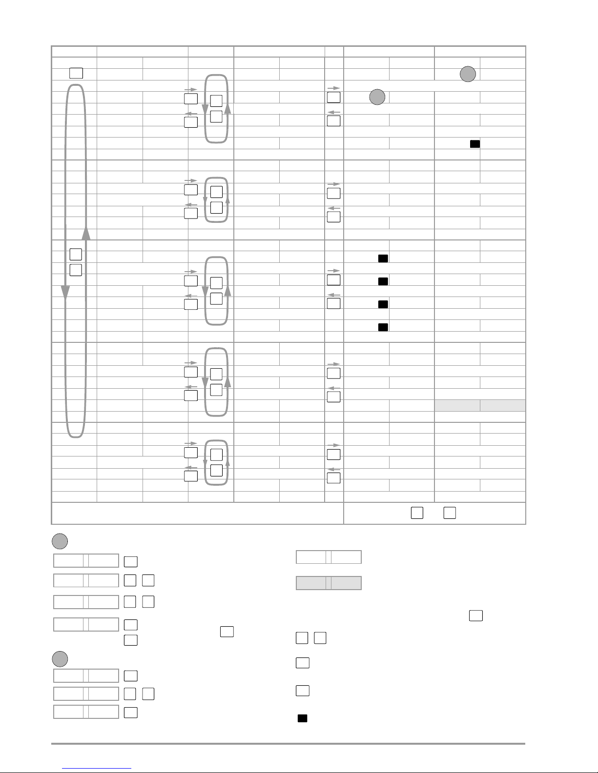
26 GMC-I Messtechnik GmbH
6 Menu Structure and Parameters
* /r15 as from firmware version 004
Main menu level Submenu level Parameters level Parameters level
Display A Display B Display A Display B Display A Display B Display A Display B
setvp devic devic limit vl_l 0. 0 . 00 vl_h 60. . 000
SETUP DEVICE Limit value parameter Voltage setting limit value, L = lower, U = upper
Setup menu
devic ovp ovp on ovdly 0. 0 . 00
Overvoltage menu Overvoltage protection on/off Overvoltage delay time
devic oCp oCp off oCdly 0. 0 . 00
Overcurrent menu Overcurrent protection on/off Overcurrent delay time
devic Cfg_d pon rst sset off
Device settings after power on
setvp dpy1f dpy1f dpy dpy-a vo dpy-b 1o
SETUP DISPLAY & INTERFACE
Digital display settings
Display A – standard display: Uo Display B – standard display: Io
Display and interface menu
dpy1f an1f trg-1 off trg-2 off
Analog interface settings Trigger input 1 on/off Trigger input 2 on/off
dpy1f bvs addr 12 bavd 9600
Interface settings Device address 6) (IEEE488) Transmission speed (RS232)
setvp seq seq ctrl seq go seq hold
SETUP SEQUENCE Access sequence
Start sequence (RUN),
footnote 3
Stop sequence
Sequence menu
seq Cond i seq-n 0 Strt 0097
Sequence settings
Sequence no. (subsequence)
footnote 1
Start address
seq ed it mem-a 0100 vset 39 . 000
Edit sequence Voltage setpoint
seq mem load 0105 store 0105
Memory functions Load sequence value Save as sequence value
setvp meas meas mm-v1 mm-v1 off v_ 9 . 992
SETUP MEASUREMENT EXTREME MEASUREMENT Min-Max memory
Minimum measured voltage value
Measuring menu
meas v1-Cs meas v1_Cs vc_ 0 . 000
meas Cfg_m m-lp 3 m-tab
meas spec
rl0ad
footnote 5
30. . 531
Avx 1nfo l-Err 000 era 3
AUXILIARY Events and status memory Last error no. Events memory A
Memory and calibration menu
vers1 rel 01 . . 001 vpd no
Firmware revision Firmware version Firmware update
adjvs 7.10.11 voff # vfs #
Balancing routine
Balancing date
Voltage setpoint zero point Voltage setpoint
upper limit
MENU
ESC
ESC
ESC
ESC
ESC
ESC
ESC
ESC
ESC
ESC
A
B
7
654
2
vl_h 60000
Set parameter (example: upper limit value for voltage setpoint)
vl_h 60000
Select entry position (decimal place).
Acknowledge selection.
vl_h 40000
Increase/decrease value – alternative:
vl_h 40000
Acknowledge parameter
ESC
Jump back to higher menu level.
A
ovp off
Select parameter – switch function on/off.
Acknowledge selection.
ovp on
Select status
ovp on
Acknowledge parameter.
B
(here: off, on, r01 ... r12/r15*).
Number blinks, NUM LED key lights up.
Enter value directly with the numeric keypad.
or abort procedure with
ESC
setup seq
LED display (display A / B)
Key
Parameter not yet set
Scroll within the parameters level.
Select submenu or parameters level.
ESC
Jump back to higher menu level.
setup seq
#
Setting value is displayed, after which the
6
Hot key for direct parameter selection
measured value is entered and acknowledged with .
Select parameters.
Page 27
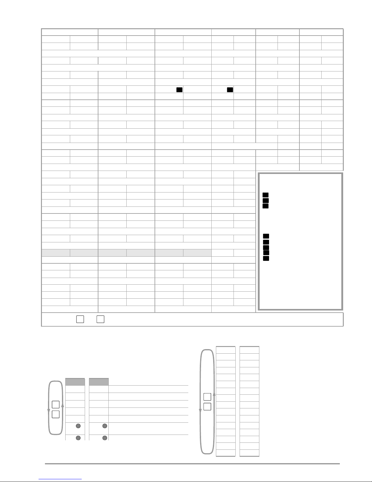
GMC-I Messtechnik GmbH 27
1 Allows for viewing and processing of the following “condi (condition) parameters”
in setup memory n specified by “Seq-n” (application: subsequences)
2 Entry of numeric value n# is additionally possible, start address n stop address,
resume sequence at memory location n#
Parameters level Parameters level Parameters level Parameters level Parameters level Parameters level
Display A Display B Display A Display B Display A Display B Display A Display B Display A Display B Display A Display B
1l_l 0.0 . 00 1l_h 60 . 000
Current setting limit value, L = lower, U = upper
ovset 40 . 000
Overvoltage protection trigger value
oCset 80 . 000
Overcurrent protection trigger value
sink off C-dyn r save 01 rcl
01 t 16 14 20 2006 08 04
Footnote 4 Footnote 5
Time (hhmm)
Year (YYYY)
M/D (mmdd)
ddc 15
Display delay time
sig-1 off sig-2 off sig-3 off a1_v off a1_1 off
Signal input 1 on/off Signal input 2 on/off Signal input 3 on/off
Voltage input on/off
Current input on/off
db 8 pb none sb 1 vsb 115.. 2t
Number of data bits (RS232) Parity bit (RS232) Stop bit (1 or 2) (RS232) Transmission speed (USB COM-Port)
Footnote 2 Footnote 2
seq cont. seq stop seq Strt seq step seq bstp seq esc
Resume sequence Stop sequence Jump to start address Forward step-by-step Backwards step-by-step Exit sequence
stop 0123 rep cont. tdef 1 . 000
Stop address Repeat sequence Default time
1set 10. . 000 tset tdef fset nf
Current setpoint Dwell time Default time Function
seq_c 0105 seq_c st-sp seq_r 0101 seq_i 0108
Delete memory location 105. Delete start-stop mem. loc. Delete & shift mem. loc. Paste & shift mem. loc.
v- 9 . 998 1_ 0 . 204. 1- 0 . 212.
Max. measured voltage value
Min. measured current value Max. measured current value
vc- 60 . 000 1c_ 0. . 000 1c- 60 . 000
m-cfg em_v em_1
erb 0 erC 0 Cra 1 crb 0
Events memory B Events memory C Status memory A Status memory B
1off # 1f5 #
Current setpoint zero point
Current setpoint
upper limit
8
9
Additional key functions:
With sequence status RUN (after GO or CONT)
[ENTER] HOLD
[ESC] Abort at actual address
[0]
Abort and jump to final value
With sequence status STOP (after Strt, Hold,
StEP or bStP)
[UP] STEP
[DOWN] BACKSTEP
[ENTER] CONT
[ESC] Abort at actual address
[0]
Abort and jump to final value
See sequence status diagram chapter 10.3
*) The sequence is also aborted at the actual
address, when turning an increment knob
or pressing a select button.
(sequence-status READY)
ESC
0
ESC
0
3 Other display options can be selected while a sequence is being executed with
the
and keys:
The display does not return automatically to the standard display setting with this
option, but rather when the sequence function has been completed or aborted.
< Selected standard display setting
MEM-A 0005
Current memory location address
rrEp cont
Remaining number of repetitions
SEq-n 00
Run is part of the main sequence
FSEt __rv
Sequence function parameter
tSEt tdEF
Memory location-specific dwell time
USEt ISET For example calculated intermediate values for
a ramp function
Uout IOUt Momentary measured values
4The and keys can be used as follows for scrolling while a selected RCL
function is being executed (displays A and B blink until the selection is
acknowledged with the ENTER key, or until the function is otherwise aborted).
rcl 02 Access setup register 02
outp on
vset 12
. 000
1set 25
. 000
pset 1500
. . 0
oup on
ovset 80
. . 00
oCp off
oCset 80 .
. 00
pon rst
trg-1 off
trg-2 off
a1-v off
1 . off
Strt 0001
stop 0005
5) Display function does not
change automatically back
to standard display
6) the modification of a device
address is not accepted
until restarting the
KONSTANTER.
Page 28

28 GMC-I Messtechnik GmbH
7 Analog Interface
7.1 Connector pin assignments
Interface
Typ e
Circuit Diagram Func-
tion
Te rm inal
Meaning
TRG
TRG 1 +
TRG 1 –
TRG 2 +
TRG 2 –
1
2
3
4
Trigger Inputs
• Floating digital control inputs for controlling a device function defined by
SEtUP/dPYIF/AnIF/trG 1 txt and SEtUP/dPYIF/AnIF/trG 2 txt
• Low signal: –18 V Us + 1 V
• High signal: + 4 V Us + 18 V
• Current consumption: Is = (Us – 2 V) / 1.47 k
SIG
SIG 1 +
SIG 1 –
SIG 2 +
SIG 2 –
SIG 3 +,
AGND 2
5
6
7
8
9
10
Signal Outputs
• Two floating digital status signal outputs
• One digital status signal output with reference to AGND (2)
•SIG 1, SIG 2 and SIG 3+ indicate the statuses defined by
SEtUP/dPYIF/AnIF/SiG 1 txt, SEtUP/dPYIF/AnIF/SiG 2 txt and
SEtUP/dPYIF/AnIF/SiG 3 txt.
• Signal type: open collector
• Max. switching voltage: 30 V DC
• Max. switching current: 20 mA
Interface
Typ e
Circuit Diagram Func-
tion
Ter m in al
Meaning
U
H
+15 V
AGND 1
AGND 2
11
12
10
+15 V (output)
• This auxiliary voltage output (15 to 18.5 V DC with reference to AGND 1
or AGND 2) can be used to control the trigger inputs, or to supply power
to external components (e.g. reference element for generating control
voltages ).
• The output is equipped with electronic current limiting to approximately
60 mA, and is short-circuit proof to AGND 1 and AGND 2.
AGND 1 and AGND 2 (analog ground = reference point)
• Reference point for the analog and digital control inputs and outputs
• These terminals are internally connected to the minus pole of the power
output via a reversible fuse with a rating of 110 mA.
The following is recommended:
• Use AGND 1 as a reference for the analog terminals on the upper
terminal strip (pins 13 through 18).
• Use AGND 2 as a reference for the digital terminals on the bottom
terminal strip (pins 1 through 9).S
Q1
1.47 k
Q1
1.47 k
100
100
100
Q2
+T
Q2
Q2
+T
U
I
20 V
60 mA
15 V
+T
Page 29
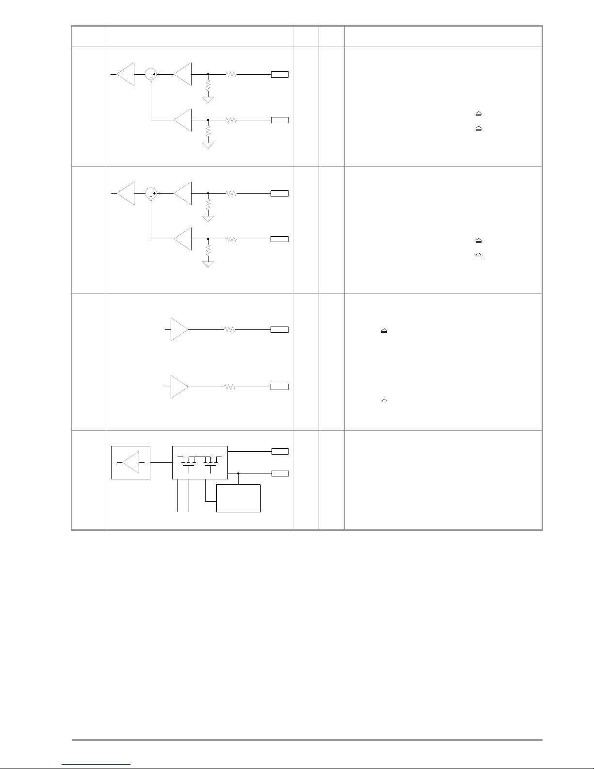
GMC-I Messtechnik GmbH 29
U
set
Uext +
Uext –1314
Uext +, Uext – (input)
• Analog (differential) voltage input with reference to AGND for controlling
the output voltage setpoint.
The following applies with activated analog setpoint (SEtUP/dPYIF/AnIF/
AI_U on):
Uset = USET + ku x U(Uext +) – ku x U(Uext –)
Uset = Resulting output voltage setpoint
USET =
Voltage setpoint, selected manually or digitally
U(Uext+) = External control voltage (0 ... 5 V 0 ... +Usetnom)
with reference to AGND 1
U(Uext –) = External control voltage (0 ... 5 V 0 ... –Usetnom)
with reference to AGND 1
ku = Control coefficient = Usetnom / 5 V
Usetnom = 60 V (SYSKON P1500-060-060)
• Input impedance: a total of 10 k each to AGND (1)
I
set
Iext +
Iext –1516
Iext +, Iext – (input)
• Analog (differential) voltage input with reference to AGND for controlling
the output current setpoint.
The following applies with activated analog setpoint (SEtUP/dPYIF/AnIF/
AI_I on):
Iset = ISET + ki x U(Iext +) – ki x U(Iext –)
Iset = Resulting output current setpoint
ISET = Current setpoint which has been selected manually or digitally
U(Iext +) = External control voltage (0 ... 5 V 0 ... –Isetnom)
with reference to AGND 1
U(Iext –) = External control voltage (0 ... 5 V 0 ... –Isetnom)
with reference to AGND 1
ki = Control coefficient = Isetnom / 5 V
Isetnom = 60 A (SYSKON P1500-060-060)
• Input impedance: a total of 10 k each to AGND (1)
Monitor
UMON
IMON1718
U MON (output)
• Analog voltage output with reference to AGND (1).
Voltage is proportional to output voltage Uout detected by the sensing
leads.
0 ... 10 V 0 ... Uoutnom.
Uoutnom = 60 V (SYSKON P1500-060-060)
• The output has an internal resistance of 8 k and is short-circuit proof.
I MON (output)
• Analog voltage output with reference to AGND (1).
Voltage is proportional to internally measured output current Iout.
0 ... 10 V 0 ... Ioutnom.
Ioutnom = 60 A (SYSKON P1500-060-060).
• The output has an internal resistance of 8 k and is short-circuit proof.
Sense
SENSE +
SENSE –1920
SENSE +, SENSE – (input)
• For connection of sensing leads for 4-wire operation – allows for
compensation of voltage drops (to 2 x 1 V) at long leads.
• Switching to 4-wire operation takes place automatically when the
SENSE – lead is connected to the appropriate output pole or negative
load pole.
Interface
Typ e
Circuit Diagram Func-
tion
Ter m in al
Meaning
9 k
1 k
0 to 5 V
9 k
1 k
0 to 5 V
9 k
1k
9 k
1k
8 k
8 k
0 to 10 V
U
I
0 to 10 V
1
2
31
2
3
Sense Control
U-Monitor
–OUT
+OUT
Page 30
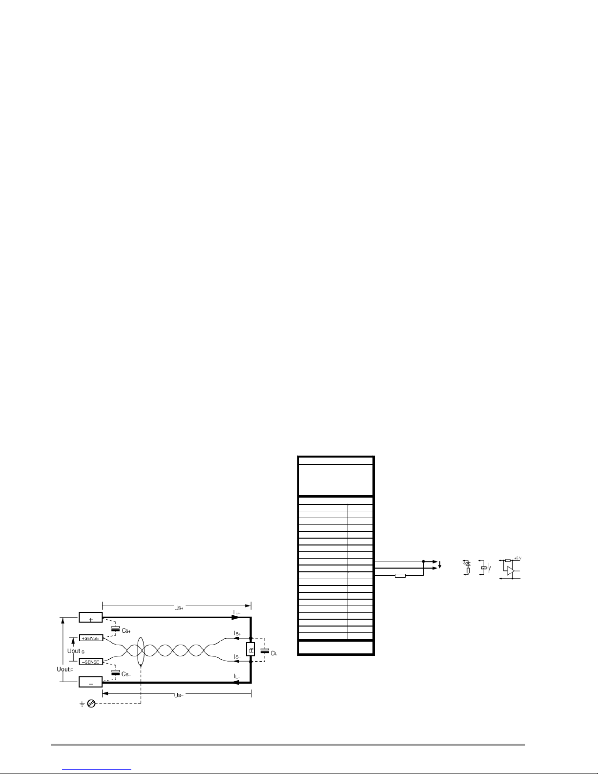
30 GMC-I Messtechnik GmbH
7.2 Auto-sensing mode
Function
Output voltage values required for voltage measuring and control
circuits can be acquired directly at the consumer instead of at the
output terminals with the help of the SENSE + and SENSE –
sensing lead terminals at the analog interface. Sensing mode
operation (remote sensing) offers the following advantages:
• In the constant voltage regulating mode, current related
voltage drops occurring in the output leads have practically no
effect on voltage supplied to the consumer. Voltage at the
output terminals is automatically increased to compensate for
voltage drops.
• In the constant current regulating mode, voltage limiting at the
consumer is independent of output current.
• Since the voltage value provided by the measuring function is
relative to the voltage value acquired at the sensing leads,
load parameters such as power consumption and load
resistance can be more accurately determined.
The parameters and limit values included in figure 7.2, and in the
chapter entitled “Electrical Data”, apply to operation with the sensing
leads.
Connection
• The two sensing lead terminals at the analog interface
(SENSE + and SENSE –) must be connected to their
respective output poles at the desired point (generally
speaking as close to the consumer as possible).
• It is advisable to twist and/or shield the sensing leads in order to
minimize interference (connect shield to the ground terminal of
the negative output pole).
• Long output and sensing lead impedances may result in
control fluctuations at the output, especially with capacitive
consumers. This effect can be counteracted by connecting
capacitors (CS+, CS-) between the SENSE and output
terminals (see figure 7.2). If the output leads are twisted, their
impedance can be reduced as well.
• Incorrect connection of the sensing leads does not damage the
KONSTANTER, although it results in the following reversible events:
– Polarity reversal at sensing leads or interrupted output lead:
If output voltage is not being limited at the KONSTANTER
by means of current regulation, it climbs to well above the
selected value which finally triggers overvoltage protection
and immediately deactivates the output.
– Interrupted SENSE + lead:
Voltage between the output terminals increases by
approximately 15%.
– Interrupted SENSE – lead:
The sensing terminals are deactivated (automatic return to
local sensing).
If the sensing leads have been connected incorrectly, rising
voltage between the output terminals is not acquired by the
measuring function.
Cs+, Cs- = 10 μF to 220 μF
Us+, Us- 1 V
Is+ U
outS
/ 180 k
Is– 0.3 mA
Figure 7.2 Connecting the Consumer for Sensing Mode Operation
Activation
• The remote sensing mode function is activated automatically after
the SENSE – terminal has been connected to the corresponding
output pole.
• The function is deactivated once again by interrupting this
connection.
7.3 Status Signal Outputs
Function
• The KONSTANTER is equipped with three digital open
collector outputs for indicating status.
– Two floating outputs SIG 1 , SIG 2 and
– One with reference to AGND:SIG 3 +
• The device status or event to be indicated is independent for
all three signal outputs.
Selection is made by setting the following functions:
– SEtUP/dPYIF/AnIF/SiG-1 txt,
– SEtUP/dPYIF/AnIF/SiG-2 txt and
– SEtUP/dPYIF/AnIF/SiG-3 txt
(see chapter 6, “Menu Structure” and chapter 7, “Operating
Commands”).
• As a status signal for monitoring devices
• For controlling external output relays
Application
• Triggering of certain device functions can be synchronized by
means of connection to the trigger inputs of other
KONSTANTERs.
Connection
• Values for connection –
Max. switching voltage: 30 V DC
Max. switching current: 20 A
• If you want to use the signal outputs to send status signals to
external monitoring devices, pull-up resistors must be used in
order to achieve appropriate levels.
The status signal outputs can be connected to the + 15 V
terminal with pull-up resistors (at least 1 k), in order to
generate an active high signal of + 15 V.
Figure 7.3 Wiring Examples for Status Signal Outputs
PSP-KONSTANTER
Einstellung
USET = Usoll
ISET = Isoll
OUTPUT ON
SEtUP/dPYIF/AnIF/SiG-3 txt
Analog Interface
TRG 1 + 1
TRG 1 - 2
TRG 2 + 3
TRG 2 - 4
SIG 1 + 5
SIG 1 - 6
SIG 2 + 7
SIG 2 - 8
SIG 3 + 9
AGND 2 10
+15V 11
AGND 1 12
Uext + 13
Uext - 14
Iext + 15
Iext - 16
U MON 17
I MON 18
SENSE + 19
SENSE - 20
+OUT
-OUT
Rpu
Usig
Page 31
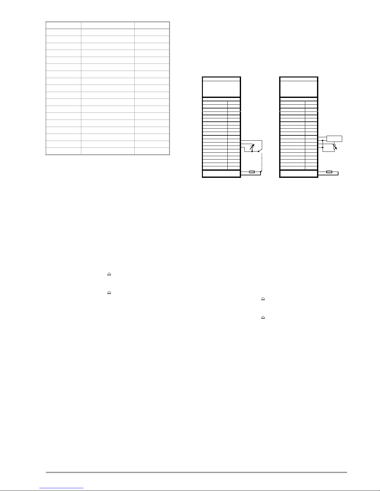
GMC-I Messtechnik GmbH 31
Setting Parameters for Status Signal Outputs
1 The signal outputs can be logically linked using the comparison function. The
comparative values are defined by parameters w1, w2, w3 and w4 from the UI_C_SET command. Momentary measured voltage and current values are
compared with these parameters and evaluated.
7.4 Regulating Output Voltage
Function
Output voltage Uout can be set by means of external control
voltage Usu = U(Uext +) – U(Uext –) via control inputs Uext +
(non-inverting) and Uext – (inverting).
• The voltage control input functions as a differential voltage input:
• The following applies with activated analog setpoint
(SEtUP/dPYIF/AnIF/AI_U on):
Uset = USET + ku x U(Uext +) – ku x U(Uext –)
Uset = Resulting output voltage setpoint
USET = Voltage setpoint which has been selected
manually or digitally
U(Uext +)
= External control voltage
(0 ... 5 V 0 ... +Usetnom)
with reference to AGND (1)
U(Uext –)
= External control voltage
(0 ... 5 V 0 ... –Usetnom)
with reference to AGND (1)
ku =Control coefficient = U
setnom
/ 5 V
U
setnom
= 60 V (SYSKON P1500-060-060)
• Max. adjusting error:
SYSKON P1500: 0.2% Unom 0.6% setting value
SYSKON P3000: 0.25% Unom 0.6% setting value
SYSKON P4500: 0.25% Unom 0.6% setting value.
• Input resistance: 10 k each
Notes
• The control inputs are not floating inputs: Their reference
point, AGND (1), is connected to the negative pole of the
power output.
• Connecting grounded circuits to the control input may result
in erroneous settings due to leakage current or ground loops.
• If the reference point of control voltage Usu is connected to the
negative output pole at the load side, the inverting input must be
connected to this point (connection b in figure 7.4). Influences
resulting from voltage drops in the output lead are thus avoided.
• If control voltage is isolated from the output, connect Uext – to
AGND (1) (connection a in figure 7.4).
• If remote adjustment of output voltage is to be accomplished
by means of a potentiometer, wiring can be laid out as shown
in figure 7.4.
• Usu can also be applied as an alternating voltage, for example
in order to superimpose manually selected direct voltage
USET with interference signals. The maximum operating
frequency of modulated output voltage depends upon voltage
amplitude, the setting selected for current limiting and load,
and thus cannot be defined with a simple formula. It is
increased as amplitude is decreased, and as current limiting
and load are increased.
Connection
Figure 7.4 Wiring for Controlling Output Voltage with External Voltage /
External Potentiometer
7.5 Controlling Output Current
Function
Output current Iout can be set with external voltage
Usi = U(Iext +) – U(Iext –) via control inputs Iext + (non-inverting)
and Iext – (inverting).
• The current control input functions as a differential voltage
input:
• The following applies with activated analog setpoint
(SEtUP/dPYIF/AnIF/AI_I on):
Iset = ISET + ki x U(Iext +) – ki x U(Iext –)
Iset = Resulting output current setpoint
ISET = Current setpoint which has been selected
manually or digitally
U(Iext +) = External control voltage
(0 ... 5 V 0 ... +Isetnom)
with reference to AGND (1)
U(Iext –) = External control voltage
(0 ... 5 V 0 ... –Isetnom)
with reference to AGND (1)
ki = Control coefficient = Isetnom / 5 V
I
setnom
= 60 A (SYSKON P1500-060-060)
• Max. adjusting error:
SYSKON P1500: 0.2% Inom 1.2% setting value
SYSKON P3000: 0.15% Inom 1.2% setting value
SYSKON P4500: 0.133% Inom 1.2% setting value
• Input resistance: 10 k each
Notes
• The control inputs are not floating inputs: Their reference
point, AGND (1), is connected to the negative pole of the
power output.
• Connecting grounded circuits to the control input may result
in erroneous settings due to leakage current or ground loops.
• If the reference point of control voltage Usi is connected to the
negative output pole at the load side, the inverting input must
be connected to this point (connection b in figure 7.5).
Influences resulting from voltage drops in the output lead are
thus avoided.
• If control voltage is isolated from the output, connect Iext – to
AGND (1) (connection a in figure 7.5).
txt Meaning – Allocation Level
OFF SIG n: direct off passive high
ON SIG n: direct on active low
OUT OUTPUT ON passive high
OUTPUT OFF active low
MODE OFF or CV passive high
CC or OL active low
SEQ READY/STOP passive high
RUN active low
SSET OFF passive high
ON active low
U_LO
1
Umeas w1 passive high
Umeas < w1 active low
U_HI
1
Umeas w2 passive high
Umeas > w2 active low
I_LO
1
Imeas w3 passive high
Imeas < w3 active low
I_HI
1
Imeas w4 passive high
Imeas > w4 active low
PSP-KONSTANTER
Einstellung
USET = 0 V
ISET = I soll
OUTPUT ON
SEtUP/dP YIF/AnIF/AI_U on
Analog Interface
TRG 1 + 1
TRG 1 - 2
TRG 2 + 3
TRG 2 - 4
SIG 1 + 5
SIG 1 - 6
SIG 2 + 7
SIG 2 - 8
SIG 3 + 9
AGND 2 10
+15V 11
AGND 1 12
Uext + 13
Uext - 14
Iext + 15
Iext - 16
U MON 17
I MON 18
SENSE + 19
SENSE - 20
+OUT
-OUT
Usu
Last
a)
b)
PSP-KONSTANTER
Einstellung
USET = 0 V
ISET = Isoll
OUTPUT ON
SEtUP/dPYIF/AnIF/ AI_U on
Analog Interface
TRG 1 + 1
TRG 1 - 2
TRG 2 + 3
TRG 2 - 4
SIG 1 + 5
SIG 1 - 6
SIG 2 + 7
SIG 2 - 8
SIG 3 + 9
AGND 2 10
+15V 11
AGND 1 12
Uext + 13
Uext - 14
Iext + 15
Iext - 16
U MON 17
I MON 18
SENSE + 19
SENSE - 20
+OUT
-OUT
2k?
Last
REF 02
IN
OUT +5V
Page 32
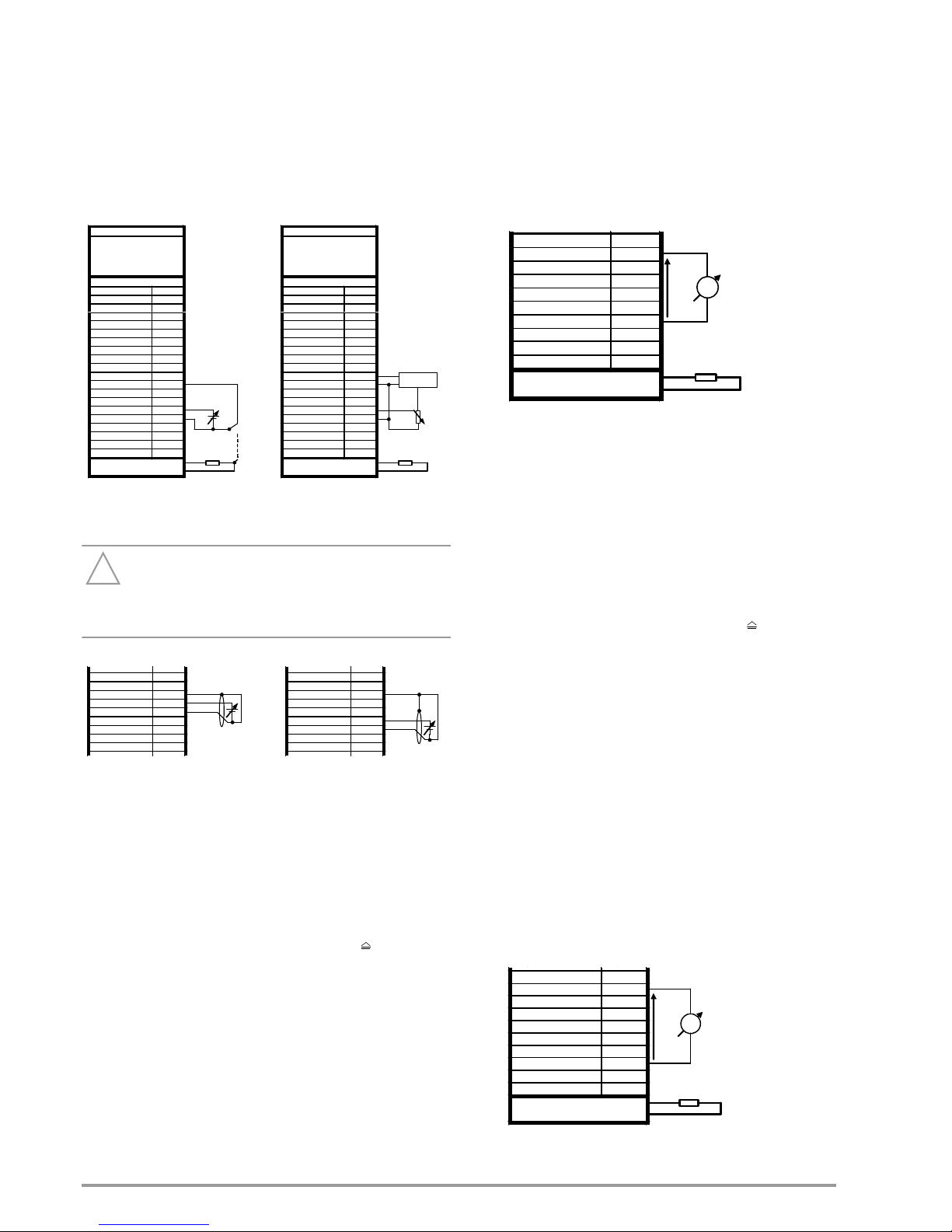
32 GMC-I Messtechnik GmbH
• If remote adjustment of output current is to be accomplished by means
of a potentiometer, wiring can be laid out as shown in figure 7.5.
• Usi can also be applied as an alternating voltage, for example
in order to superimpose manually selected direct current ISET
with interference signals. To a great extent, the maximum
operating frequency of modulated output current depends
upon the output current value, as well as the voltage
amplitude which results from the prevailing load, and thus
cannot be defined with a simple formula. It is increased as
amplitude is decreased, and as load is increased.
Connection
Figure 7.5 Wiring for Controlling Output Current with External Voltage /
External Potentiometer
Attention!
!
Control inputs Uext +, Uext – and Iext +, Iext – should
only be connected with shielded cable.
Connect the shield to the AGND (1) reference point.
7.6 Voltage Monitoring Output
Function
• The U MON terminal reads out voltage Umu with reference to
AGND (1), which is proportional to output voltage Uout.
• U MON serves as a control voltage for master-slave series
connection.
• However, U MON can also be used for external measuring,
monitoring and recording.
• The following applies:
Umu = Uout x kmu x kload (kload = 1: 0 ... 10 V 0 ... Uoutnom)
kmu = 10 V / Uoutnom; U-monitor coefficient
kload = Rload / (Rload + Ri); load coefficient
Ri(U MON)
=8k; U-monitor internal resistance
Rload = Load resistance (internal resistance of the
measuring instrument)
Uoutnom
= 60 V (SYSKON P1500-060-060)
• Max. error for Umu/kmu (where Rload > 10 M):
SYSKON P1500: 0.2% Unom 0.4% actual value
SYSKON P3000: 0.3% Unom 0.6% actual value
SYSKON P4500: 0.3% Unom 0.8% actual value
Notes
• U MON is not a floating output: Its reference point, AGND (1),
is connected to the negative output pole.
• Connecting grounded measuring circuits to the monitor
output may result in erroneous measurements due to leakage
current or ground loops.
• The voltage monitoring output makes reference to output
voltage acquired at the sensing leads.
• The monitor output is short-circuit proof.
Internal resistance is 8 k.
Connection
Figure 7.6 Voltage Monitor Wiring
7.7 Current Monitoring Output
Function
• The I MON terminal reads out voltage Umi with reference to
AGND (1), which is proportional to output current Iout.
• I MON serves as a control voltage for master-slave parallel
connection.
• However, I MON can also be used for external measuring,
monitoring and recording.
• The following applies:
Umi = Iout x kmi x kload (kload = 1: 0 ... 10 V 0 ... Ioutnom)
kmi = 10 V / Ioutnom; I-monitor coefficient
kload = Rload / (Rload + Ri); load coefficient
Ri(I MON)
=8k; I-monitor internal resistance
Rload = Load resistance (internal resistance of the
measuring instrument)
Ioutnom
= 60 A (SYSKON P1500-060-060)
• Max. error for Umi/kmi (where Rload > 10 M):
SYSKON P1500: 0.3% Inom 1.2% actual value
SYSKON P3000: 0.2% Inom 1.2% actual value
SYSKON P4500: 0.167% Inom 1.2% actual value
Notes
• I MON is not a floating output: Its reference point, AGND (1), is
connected to the negative output pole.
• Connecting grounded measuring circuits to the monitor
output may result in erroneous measurements due to leakage
current or ground loops.
• The monitor output is short-circuit proof.
Internal resistance is 8 k.
Connection
Figure 7.7 Current Monitor Wiring
PSP-KONSTANTER
Einstellung
USET = Usoll
ISET = 0 A
OUTPUT ON
SEtUP/dP YIF/AnIF/AI_I on
Analog Interface
TRG 1 + 1
TRG 1 - 2
TRG 2 + 3
TRG 2 - 4
SIG 1 + 5
SIG 1 - 6
SIG 2 + 7
SIG 2 - 8
SIG 3 + 9
AGND 2 10
+15V 11
AGND 1 12
Uext + 13
Uext - 14
Iext + 15
Iext - 16
U MON 17
I MON 18
SENSE + 19
SENSE - 20
+OUT
-OUT
Usi
Last
a)
b)
PSP-KONSTANTER
Einstellung
USET = Usoll
ISET = 0 A
OUTPUT ON
SEtUP/dP YIF/AnIF/AI_I on
Analog Interface
TRG 1 + 1
TRG 1 - 2
TRG 2 + 3
TRG 2 - 4
SIG 1 + 5
SIG 1 - 6
SIG 2 + 7
SIG 2 - 8
SIG 3 + 9
AGND 2 10
+15V 11
AGND 1 12
Uext + 13
Uext - 14
Iext + 15
Iext - 16
U MON 17
I MON 18
SENSE + 19
SENSE - 20
+OUT
-OUT
2k?
Last
REF 02
IN
OUT +5V
SIG 3
+
9
AGND 2 10
+15V 11
AGND 1 12
Uext + 13
Uext - 14
Iext + 15
Iext - 16
U MON 17
I MON 18
Usu
SIG 3
+
9
AGND 2 10
+15V 11
AGND 1 12
Uext + 13
Uext - 14
Iext + 15
Iext - 16
U MON 17
I MON 18
Usi
+15V 11
AGND 1 12
Uext + 13
Uext - 14
Iext + 15
Iext - 16
U MON 17
I MON 18
SENSE + 19
SENSE - 20
+OUT
-OUT
Last
V
Rbel
Umu
AGND 2 10
+15V 11
AGND 1 12
Uext + 13
Uext - 14
Iext + 15
Iext - 16
U MON 17
I MON 18
SENSE + 19
SENSE - 20
+OUT
-OUT
Last
V
Rbel
Umi
Page 33

GMC-I Messtechnik GmbH 33
7.8 Trigger Inputs
Function
• Floating optocoupler inputs TRG 1 and TRG 2 allow for
remote control of a device function with the help of a binary
signal.
• The function to be controlled is selected by manually or
digitally configuring the trigger mode
(SEtUP/dPYIF/AnIF/trG 1 txt or SEtUP/dPYIF/AnIF/trG 2 txt).
Connection
• Connect the control signal between TRG 1(2) + and
TRG 1(2) –.
Signal level:
Low signal: – 18 V Us + 1 V
High signal: + 4 V Us + 18 V
Current consumption: Is = (Us – 2 V) / 1.47 k
• The TRIGGER input can be driven with the + 15 V output at
the analog interface via any desired switch (figure 7.8).
Warning!
Trigger inputs TRG 1 and TRG 2 are floating inputs
and are functionally isolated from the output current
circuit. This functional isolation is not equivalent to
“safety separation” as specified in electrical safety
regulations.
Note
The trigger inputs are sampled by the digital control unit
approximately every 10 ms. After a signal change has been
detected, repeated querying ensues at short time intervals
(suppression of switch bouncing and interference pulses). This
means that:
• Trigger signal pulses must have a minimum duration of 14 ms
in order to assure reliable recognition.
• A delay of 1 to 15 ms may occur between application of the
control signal and triggering of the controlled function.
Connection
Figure 7.8 Controlling the Trigger Input with a Switching Element / Exter-
nal Signal
Trigger Function Setting Parameters
PSP-KONSTANTER
Einstellung
USET = Usoll
ISET = Is oll
OUTPUT ON
T-MODE z OFF
Analog Interface
TRG 1 + 1
TRG 1 - 2
TRG 2 + 3
TRG 2 - 4
SIG 1 + 5
SIG 1 - 6
SIG 2 + 7
SIG 2 - 8
SIG 3 + 9
AGND 2 10
+15V 11
AGND 1 12
Uext + 13
Uext - 14
Iext + 15
Iext - 16
U MON 17
I MON 18
SENSE + 19
SENSE - 20
+OUT
-OUT
Last
Rbel
Us
PSP-KONSTANTER
Einstellung
USET = Usoll
ISET = Isoll
OUTPUT ON
T-MODE z OFF
Analog Interface
TRG 1 + 1
TRG 1 - 2
TRG 2 + 3
TRG 2 - 4
SIG 1 + 5
SIG 1 - 6
SIG 2 + 7
SIG 2 - 8
SIG 3 + 9
AGND 2 10
+15V 11
AGND 1 12
Uext + 13
Uext - 14
Iext + 15
Iext - 16
U MON 17
I MON 18
SENSE + 19
SENSE - 20
+OUT
-OUT
Last
Parameters Meaning
OFF Trigger input function is deactivated, trigger signals have no
effect.
OUT OUTPUT Trigger signal acts upon the OUTPUT: output on/off.
Low OUTPUT depends upon manual setting or programming
command.
Edge
Low High
OUTPUT remains OFF or OUTPUT is switched OFF.
High OUTPUT is OFF and cannot be activated (neither manually
nor by means of a program command).
Edge
High Low
The OUTPUT is activated; exception: OTP or OVP.
SQS Step
function
Memory recall (step-by-step sequence control)
Edge
Low High
Start trigger signal
High – The trigger signal is a high pulse with a duration of less
than 800 ms.
– A high pulse with a duration > 1.0 s resets the address
counter to the start address at any point in time, and
execution begins with the next trigger signal.
Edge
High Low
The high low edge of the (short) trigger signal results in
step-by-step control of the currently selected sequence,
regardless of the specified time and number of repetitions.
Recall of the memory’s contents begins with the START
address. Each trigger signal increasers the address by 1,
until the STOP address is reached. The next pulse once
again causes execution of the contents of the START
address.
SEQ SEQUENCE Sequence execution control
Edge
Low High
The SEQUENCE function is started beginning with the start
address (SEQUENCE GO).
Edge
High Low
Ends sequence execution by jumping to the stop address
LLO LOCAL
LOC KED
Front panel control disabling
Low All front panel controls are functional.
High All front panel controls are disabled except for the mains
switch, and activation is not possible with the LOCAL key.
MIN MINMAX Storage of Min-Max values for U and I is controlled when
the MINMAX function is activated (MINMAX ON)(UI_ ON).
Low The Min-Max function is active.
Edge
Low High
The Min-Max function is deactivated. Values in the
Min-Max memories remain unchanged.
High The Min-Max function is inactive.
Edge
High Low
Values in the Min-Max memories are reset and replaced
with momentary output values.
The Min-Max function is activated.
AIX Analog Input Uext, Iext
Low Analog setpoints not switched through
High Analog setpoints switched through
AIU Analog Input Uext
Low Analog setpoint not switched through
High Analog setpoint switched through
AII Analog Input Iext
Low Analog setpoint not switched through
High Analog setpoint switched through
Page 34
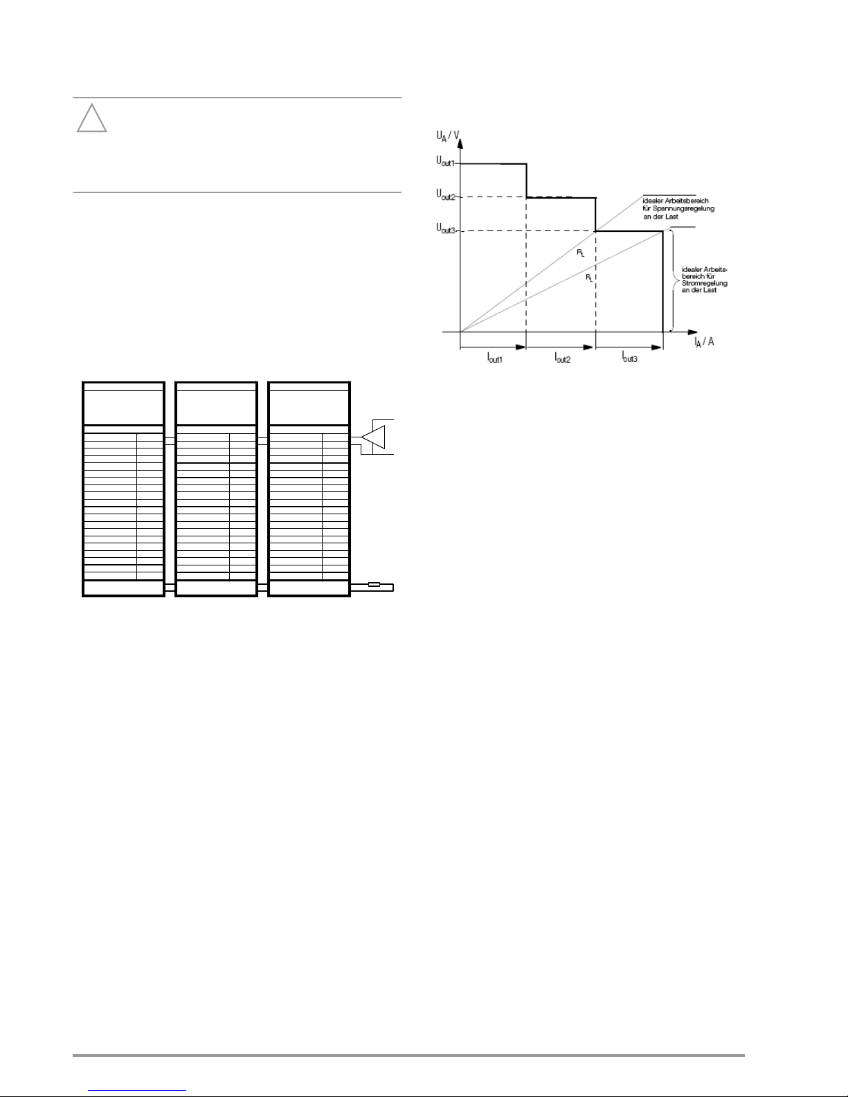
34 GMC-I Messtechnik GmbH
7.9 Parallel Connection
If output current from a single KONSTANTER is insufficient for the
respective application, the outputs of any number of
KONSTANTERs can be parallel connected.
Attention!
!
If outputs with different nominal voltages are parallel
connected, all outputs must be limited to the lowest
utilized nominal voltage value. The ULIM parameter is
used to select this setting.
7.9.1 Direct Parallel Connection
Function
• Easiest way to provide the consumer with more current than
is available from a single r KONSTANTER.
• KONSTANTERs with differing nominal output voltages can be
used. However, all voltage setpoints must be set or limited to
the same value.
• This setup is less suitable for the constant voltage regulating
mode.
Wiring
Figure 7.9.1a Wiring for Direct Parallel Connection
Settings
• Deactivate all outputs.
• Adjust voltage setpoint USET at all parallel connected
KONSTANTER to approximately the same value:
• Uset = USET1 = USET2 = USET3 = ... = USETn
• Adjust current setpoints ISET such that they add up to the
desired cumulative current value Iset:
• Iset = ISET1 + ISET2 + ISET3 + ... + ISETn
• Activate the outputs.
Functional Principle
• After switching the outputs on, load current is initially supplied
by the KONSTANTER with the highest voltage setting.
• If load resistance is continuously reduced, load current is
continuously increased.
• When load current reaches the ISET value selected for the
output which is momentarily supplying power to the
consumer, current limiting is activated at this output.
• If load resistance is further decreased, current regulation
reduces output voltage until the voltage value of the output
with the next lower setting is reached.
• As of this point in time, this KONSTANTER also supplies a
portion of the load current.
• This procedure is continued until load current triggers current
regulating at the output with the lowest voltage setting when
the setpoint value for cumulative current is reached.
• This output maintains constant load current until the load
resistor is short-circuited.
Figure 7.9.1b U / I Diagram for Direct Parallel Connection
Notes
• Slightly varying voltages occur at the individual outputs as a
result of setting tolerances.
• In the event of larger voltage differences, an electronic sink is
activated at the outputs with lower voltage settings.
• The sink controller attempts to reach the lower voltage value
by limiting power consumption.
• Neither the KONSTANTERs nor the power consumer are
damaged as a result.
• If problems occur with the measurement of load current, the
KONSTANTERs should be linked by means of master-slave
parallel connection.
• The outputs can be activated and deactivated commonly by
connecting the trigger inputs in parallel (see figure 7.9.1a,
optional connection) or series (setting: “SEtUP/dPYIF/AnIF/
trG-1 out”).
PSP-KONSTANTER 3
Einstellung
USET = Usoll
ISET 1
OUTPUT ON
(
SEtUP/dPYI F/AnIF/trG-1 out)
Analog Interface
TRG 1 + 1
TRG 1 - 2
TRG 2 + 3
TRG 2 - 4
SIG 1 + 5
SIG 1 - 6
SIG 2 + 7
SIG 2 - 8
SIG 3 + 9
AGND 2 10
+15V 11
AGND 1 12
Uext + 13
Uext - 14
Iext + 15
Iext - 16
U MON 17
I MON 18
SENSE + 19
SENSE - 20
+OUT
-OUT
optional
PSP-KONST ANTER 1
Einstellung
USET = Usoll
ISET 3
OUTPUT ON
(
SEtUP/dPYIF/AnIF/trG-1 out)
Analog Interface
TRG 1 + 1
TRG 1 - 2
TRG 2 + 3
TRG 2 - 4
SIG 1 + 5
SIG 1 - 6
SIG 2 + 7
SIG 2 - 8
SIG 3 + 9
AGND 2 10
+15V 11
AGND 1 12
Uext + 13
Uext - 14
Iext + 15
Iext - 16
U MON 17
I MON 18
SENSE + 19
SENSE - 20
+OUT
-OUT
Last
PSP-KONSTANTER 2
Einstellung
USET = Usoll
ISET 2
OUTPUT ON
(
SEtUP/dPYIF /AnIF/trG-1 out)
Analog Interface
TRG 1 + 1
TRG 1 - 2
TRG 2 + 3
TRG 2 - 4
SIG 1 + 5
SIG 1 - 6
SIG 2 + 7
SIG 2 - 8
SIG 3 + 9
AGND 2 10
+15V 11
AGND 1 12
Uext + 13
Uext - 14
Iext + 15
Iext - 16
U MON 17
I MON 18
SENSE + 19
SENSE - 20
+OUT
-OUT
Us
Page 35

GMC-I Messtechnik GmbH 35
7.9.2 Master-Slave Parallel Connection
Function
As opposed to direct parallel connection, master-slave parallel
connection offers significant advantages:
• Equally suitable for voltage and current regulation
• Output parameters (output voltage, cumulative current
limiting) are set entirely by the master device.
• All interconnected KONSTANTERs are equally loaded.
Wiring
• Define one power supply as a master device.
• Connect master and slave devices as shown in figure 7.9.2.
• Connect the output leads.
• Balance the individual output current values. Keep connector
cables as short as possible, and use the largest possible
conductor cross-section. Execute balancing with Rsym (set
potentiometer to approx. 2 k).
Figure 7.9.2 Wiring for Master-Slave Parallel Connection
Settings
Initial power-up:
• Short circuit the load.
• Switch the master on (mains) and configure settings:
(Pon rcl)
if desired
OUTPUT off
USET = Uset
Desired output voltage
ISET = Iset / n
Iset: desired cumulative output current;
n: number of devices
Only valid if nominal data are identical for all
devices, see notes.
• Switch slave 1 on (mains) and configure:
(Pon rcl) if desired
USET > USET master
The voltage setpoint at the slave devices must
be set at least 1% higher than at the master
device, e.g. to maximum.
ISET = 0 A Deactivate the ISET rotary knob if applicable
by setting ILIM to 0 A.
SEtUP/dPYIF/AI_I on
Activates the analog current setpoint
• Use the same procedure for additional slave devices.
• Press the OUTPUT ON key at the slave(s) and the master.
• Check output current at the slave device displays.
• Output current at each of the slaves can be precisely matched
to master output current by adjusting Rsym.
• Changes appear immediately at the respective display.
• Undo short-circuiting of the load.
From this point on, setting and regulation of (cumulative) output
parameters are controlled entirely by the master device.
Power-up after initial settings:
Devices can be switched on and off in any desired order.
Functional Principle
The master controls output current of the downstream device
(slave 1) via the slave’s current control input with the help of the
current monitoring signal.
Slave 1 functions as a master device for the next downstream
slave (slave 2), and so forth.
Cumulative output current is thus always proportional to master
output current.
Notes
KONSTANTERs with differing nominal values:
The KONSTANTER with the smallest nominal voltage value must
always be used as the master device.
The voltage setting range of the other KONSTANTERs must be
limited to this lowest value using the ULIM parameter.
General
• The current regulator’s dynamics can be slowed down in
order to achieve more stable performance. Select the
following setting to this end “SEtUP/dEVic/CFG d/C dYn L”.
• Rsym can be implemented as a 2 k fixed resistor; adjusting
error for the slaves is increased somewhat as a result.
• A wire connection can be used instead of Rsym and Rminus
can be omitted, if no precise setpoint value is required for
cumulative output current. In this case, each slave device
supplies slightly more current than the master device.
• If analog interface connector cables and the sensing leads are
longer than 1 meter, shielded cable should be used. The
shield is connected to the ground terminal on the housing or
to - OUT.
• The master device’s measuring function acquires commonly
generated output voltage for all interconnected
KONSTANTERs, but only acquires its own output current.
• The individual measured current values for each of the
interconnected KONSTANTERs must be added together in
order to arrive at cumulative output current.
• In order to assure that the slaves’ OUTPUT ON status is
activated along with the master’s OUTPUT ON status via the
signal output and trigger input circuit as shown in figure 7.9.2,
“SEtUP/dPYIF/AnIF/SiG-(x1) out” must be selected at the
master and “SEtUP/dPYIF/AnIF/trG-(x2) out” must be
selected at the slaves, (x1) and (x2) in example 1.
The master’s OUTPUT ON status can be optionally controlled
via the trigger input – setting at the master:
“SEtUP/dPYIF/AnIF/trG-(x3) out”, (x3) in example 1.
PSP-KONSTANTER 3
Einstellung
USET = Unenn
ISET = 0 A
OUTPUT ON
SEtUP/dPYIF/AnIF/AI_I on
(
SEtUP/dPYIF/AnIF/ trG-1 out)
Analog Interface
TRG 1 + 1
TRG 1 - 2
TRG 2 + 3
TRG 2 - 4
SIG 1 + 5
SIG 1 - 6
SIG 2 + 7
SIG 2 - 8
SIG 3 + 9
AGND 2 10
+15V 11
AGND 1 12
Uext + 13
Uext - 14
Iext + 15
Iext - 16
U MON 17
I MON 18
SENSE + 19
SENSE - 20
+OUT
íOUT
PSP-KONSTANTER 2
Einstellung
USET = Unenn
ISET = 0 A
OUTPUT ON
SEtUP/dPYIF/AnIF/AI_I on
(
SEtUP/dPYIF/AnIF/ trG-1 out)
Analog Interface
TRG 1 + 1
TRG 1 - 2
TRG 2 + 3
TRG 2 - 4
SIG 1 + 5
SIG 1 - 6
SIG 2 + 7
SIG 2 - 8
SIG 3 + 9
AGND 2 10
+15V 11
AGND 1 12
Uext + 13
Uext - 14
Iext + 15
Iext - 16
U MON 17
I MON 18
SENSE + 19
SENSE - 20
+OUT
íOUT
PSP-KONSTANTER 1
Einstellung
USET = Usoll
ISET = Isoll/n
OUTPUT ON
(
SEtUP/dPYIF/AnIF/SIG-1 out)
(
SEtUP/dPYIF/AnIF/ trG-1 out)
Analog Interface
TRG 1 + 1
TRG 1 - 2
TRG 2 + 3
TRG 2 - 4
SIG 1 + 5
SIG 1 - 6
SIG 2 + 7
SIG 2 - 8
SIG 3 + 9
AGND 2 10
+15V 11
AGND 1 12
Uext + 13
Uext - 14
Iext + 15
Iext - 16
U MON 17
I MON 18
SENSE + 19
SENSE - 20
+OUT
íOUT
Last
optional
Us
Rsym
5 k
Rminus
10 k
Rsym
5 k
Rminus
10 k
Slave 2 Master Slave 1
Page 36

36 GMC-I Messtechnik GmbH
7.10 Series Connection
If output voltage from a single KONSTANTER is insufficient, or if
you want to generate a voltage, the outputs of several
KONSTANTERs can be connected in series.
Warning!
Maximum allowable cumulative voltage for series
connection is 240 V (or 480 V with grounded neutral
point).
7.10.1 Direct Series Connection
Attention!
!
If outputs with differing nominal values are series
connected, the highest selected current value is present
at all outputs in the event of short-circuit. However, the
internal reverse-voltage protection diode is only rated for
nominal current of the respective device (see reverse
voltage withstand under “Electrical Data”). For this
reason, all current setpoints must be set to the lowest
nominal current value of all interconnected devices.
The ILIM parameter is used to select this setting.
Function
• The easiest way to supply the consumer with more voltage
than is available from a single KONSTANTER
•Easy wiring
• Less suitable for constant current regulating mode.
Wiring
Figure 7.10.1a Wiring for Direct Series Connection
Settings
• Deactivate all outputs.
• Adjust current setpoint ISET at all series connected
KONSTANTER to approximately the same value:
• Iset = ISET1 = ISET2 = ISET3 = ... = ISETn
• Adjust voltage setpoints USET such that they add up to the
desired cumulative voltage value Uset:
• Uset = USET1 + USET2 + USET3 + ... + USETn
• Activate the outputs.
Functional Principle
The sum of all individual output voltages is made available to the
power consumer.
If load resistance is continuously reduced, all of the outputs
deliver the same load current at first.
When load current reaches the lowest selected current setpoint
value, current regulating is triggered at the respective output.
If load resistance is further reduced, this output maintains
constant load current until its output voltage has dropped to 0 V.
If even further reduction of load current occurs, the affected
output is forced by the other outputs to generate a negative
voltage. As of approximately –0.5 V, the internal reverse-voltage
protection diode becomes conductive.
Load current can once again climb, until current regulation is
activated at the output with the next higher current setpoint value.
This procedure is continued until load current triggers current
regulating at the output with the highest current setpoint value.
Current is held constant by this last output until short-circuiting
occurs.
Figure 7.10.1b U / I Diagram for Direct Series Connection
Note
The outputs can be activated and deactivated commonly by
connecting the trigger inputs in parallel (see figure 7.10.1a,
optional connection) or series (setting: “SEtUP/dPYIF/AnIF/trG
1out”).
PSP-KONSTANTER 2
Einstellung
USET = Usoll
ISET 1
OUTPUT ON
(
SEtUP/dPYI F/AnIF/trG-1 out)
Analog Interface
TRG 1 + 1
TRG 1 - 2
TRG 2 + 3
TRG 2 - 4
SIG 1 + 5
SIG 1 - 6
SIG 2 + 7
SIG 2 - 8
SIG 3 + 9
AGND 2 10
+15V 11
AGND 1 12
Uext + 13
Uext - 14
Iext + 15
Iext - 16
U MON 17
I MON 18
SENSE + 19
SENSE - 20
+OUT
-OUT
optional
PSP-KONSTANTER 1
Einstellung
USET = Usoll
ISET 3
OUTPUT ON
(
SEtUP/dPYIF/AnIF/trG-1 out)
Analog Interface
TRG 1 + 1
TRG 1 - 2
TRG 2 + 3
TRG 2 - 4
SIG 1 + 5
SIG 1 - 6
SIG 2 + 7
SIG 2 - 8
SIG 3 + 9
AGND 2 10
+15V 11
AGND 1 12
Uext + 13
Uext - 14
Iext + 15
Iext - 16
U MON 17
I MON 18
SENSE + 19
SENSE - 20
+OUT
-OUT
Last
Us
- - - - = optionale Sensev erbindung
Page 37

GMC-I Messtechnik GmbH 37
7.10.2 Master-Slave Series Connection
Function
As opposed to direct series connection, master-slave series
connection offers significant advantages:
• Equally suitable for voltage and current regulation
• Output parameters (cumulative output voltage, current
limiting) are set entirely by the master device.
• All interconnected KONSTANTERs are equally loaded.
Wiring
• Define one power supply as a master device.
• Connect master and slave devices as shown in figure 7.10.2.
• Connect the output leads to the series circuit phase terminals.
• Balance the individual output voltage values with Rsym.
Figure 7.10.2 Wiring for Master-Slave Series Connection
Settings
Initial power-up:
• Do not load the outputs (idle).
• Switch the master on (mains) and configure settings:
(Pon rcl) if desired
OUTPUT off
USET = Uset/n Uset: cumulative output voltage
n: number of devices
Only valid if nominal data are
identical for all devices, see notes.
ISET = Iset Current limit value
• Switch slave 1 on and configure:
(Pon rcl) if desired
USET = 0 VThe USET rotary knob can be deactivated if
applicable by setting ULIM to 0 V.
ISET > ISETmaster
The current setpoint at the slave devices must
be set at least 1% higher than at the master
device, e.g. to maximum.
SEtUP/dPYIF/AI_U on
Activates the analog voltage setpoint
• Use the same procedure for additional slave devices.
• Press the OUTPUT ON key at the master.
• Check output voltage at the KONSTANTER displays.
• Output voltage at each of the slaves can be precisely
matched to master output voltage by adjusting Rsym.
Changes appear immediately at the respective display.
• Connect the load.
From this point on, setting and regulation of (cumulative) output
parameters are controlled entirely by the master device.
Power-up after initial settings:
Devices can be switched on and off in any desired order.
Functional Principle
The master controls output voltage of the downstream
KONSTANTER (slave 1) via the slave’s voltage control input with
the help of the voltage monitoring signal.
Slave 1 functions as a master device for the next downstream
slave (slave 2), and so forth.
Cumulative output voltage is thus always proportional to master
output voltage.
Notes
KONSTANTERs with differing nominal values:
The KONSTANTER with the smallest nominal current value must
always be used as the master device.
The current setting range of the other KONSTANTERs must be
limited to this lowest value with the ILIM parameter.
General
• If analog interface connector cables and the sensing leads are
longer than 1 meter, shielded cable should be used.
• The shield is connected to the ground terminal on the
housing, or to –OUT.
General
• Rsym can be implemented as a 2 k fixed resistor; adjusting
error for the slaves is increased somewhat as a result.
• If Rminus is omitted, the standard value for Rsym is increased
to 122 k.
• If analog interface connector cables and the sensing leads are
longer than 1 meter, shielded cable should be used. The
shield is connected to the ground terminal on the housing or
to - OUT.
• The same current value is available from all KONSTANTERs.
For this reason, current measured at the master device is
sufficient for the measurement of load current.
• The individual measured voltage values for each of the
interconnected KONSTANTERs must be added together in
order to arrive at cumulative output voltage.
• In order to assure that the slaves’ OUTPUT ON status is
activated along with the master’s OUTPUT ON status via the
signal output and trigger input circuit as shown in figure
7.10.2, “SEtUP/dPYIF/AnIF/SiG-(x1) out” must be selected at
the master and “SEtUP/dPYIF/AnIF/trG-(x2) out” must be
selected at the slaves, (x1) and (x2) in example 1.
The master’s OUTPUT ON status can be optionally controlled
via the trigger input – setting at the master:
“SEtUP/dPYIF/AnIF/trG-(x3) out”, (x3) in example 1.
PSP-KONSTANTER 2
Einstellung
USET = 0 V
ISET = Inenn
OUTPUT ON
SEtUP/dPYIF/AnIF/AI_U on
(
SEtUP/dPYIF/AnIF/trG-1 out)
Analog Interface
TRG 1 + 1
TRG 1 - 2
TRG 2 + 3
TRG 2 - 4
SIG 1 + 5
SIG 1 - 6
SIG 2 + 7
SIG 2 - 8
SIG 3 + 9
AGND 2 10
+15V 11
AGND 1 12
Uext + 13
Uext - 14
Iext + 15
Iext - 16
U MON 17
I MON 18
SENSE + 19
SENSE - 20
+OUT
íOUT
PSP-KONSTANTER 1
Einstellung
USET = Usoll/n
ISET = Isoll
OUTPUT ON
(
SEtUP/dPYIF/AnIF/SIG-1 out)
(
SEtUP/dPYIF/AnIF/trG-1 out)
Analog Interface
TRG 1 + 1
TRG 1 - 2
TRG 2 + 3
TRG 2 - 4
SIG 1 + 5
SIG 1 - 6
SIG 2 + 7
SIG 2 - 8
SIG 3 + 9
AGND 2 10
+15V 11
AGND 1 12
Uext + 13
Uext - 14
Iext + 15
Iext - 16
U MON 17
I MON 18
SENSE + 19
SENSE - 20
+OUT
íOUT
Last
optional
Us
í í í í = optionale Senseverbindung
Rsym
5 k
Rminus
10 k
Slave Master
Page 38

38 GMC-I Messtechnik GmbH
7.11 Varying the Internal Output Resistance Value
Function
In the voltage regulating mode, internal output resistance has a
value of close to 0 .
The internal output resistance value can be increased for certain
applications, for example simulation of long output cables or
weak automotive batteries. The selected (open-circuit) output
voltage is reduced in proportion to increasing load (figure 7.11 a)
Figure 7.11a Output Voltage with Reference to Load
Calculation
The following applies:
where Rext 0
where 0 Ri 1.11
Figure 7.11b Wiring for Varying Internal Resistance
R
i
20k W
18k W R
ext
+
-----------------------------
=
R
ext
20k W
R
i
-------------
W 18k–=
PSP-KONSTANTER
Einstellung
USET = Usoll
ISET = Isoll
OUTPUT ON
Analog Interface
TRG 1 + 1
TRG 1 - 2
TRG 2 + 3
TRG 2 - 4
SIG 1 + 5
SIG 1 - 6
SIG 2 + 7
SIG 2 - 8
SIG 3 + 9
AGND 2 10
+15V 11
AGND 1 12
Uext + 13
Uext - 14
Iext + 15
Iext - 16
U MON 17
I MON 18
SENSE + 19
SENSE - 20
+OUT
-OUT
Last
R
ext
Page 39

GMC-I Messtechnik GmbH 39
8 Descriptions of Operating Commands
All setting and query commands are described and listed
alphabetically in the following pages.
Commands with an asterisk (*) are at the beginning of the list.
Each heading includes the command, along with its abbreviation.
Insofar as query commands exist (identified with a question mark
?), they are listed as well.
The next line (with the hand symbol) indicates how the respective
command can be executed manually. If keys are required, they
are mentioned as well.
The note “Menu” indicates that the respective command can be
executed from the menu.
If no manual procedure for executing the command exists, this is
indicated with a long dash (—).
Details on Memory Locations
Depending on the firmware version, a different number of memory
lodations is available, see table below.
Function „General-RESET“ (manual operation only)
Function „General-RESET“ deletes the complete user memory:
setup memory, sequence memory, interface settings.
The default values are set, see default settings of the respective
setting commands.
The following data remain unchanged: Device balancing parameters, production/serial number as well as time and date setting.
Attention!
!
Before performing a „General-RESET“, we recommend
that you note or save your setting parameters, e.g. via
the STORE command.
To perform a „General-RESET“, press and hold the cursor keys
and
during „POWER ON“ until „rdy“ blinks in the display.
*CLS – Clear Status
—
Function
The *CLS command clears all event registers and the status byte
register, except for the MAV bit (M
essage AVailable). Any existing
service requests are cancelled.
Addressing status Unchanged
Input and output buffers Unchanged
Service request SRQ Cleared
Status byte register STB Cleared except for MAV bit
Event registers ESR, ERA, ERB, ERC Cleared
Enable registers ESE, ERAE, ERBE, ERCE, SRE, PREUnchanged
Set or stored parameters Unchanged
The *CLS setting command also clears the error number list (first
3 parameters) in the response to the “ERROR? query command:
“ERROR 000,000,000,xxx”
Setting Command
Syntax: *CLS
*DDT, *DDT? – Define Device Trigger
—
Function
A list of commands including up to 80 characters can be entered
to a register with the “define device trigger” command. The *DDT
command list is executed after receiving the *TRG device
message or the IEC bus command GET (GROUP EXECUTE
TRIGGER). The content of the DDT register can be read out with
the *DDT? query command. Maximum response string length: 80
characters.
Setting Command
Syntax: *DDT
command[/command
][/
command
] ...
|— max. 80 characters —–|
Default setting
or after RESET (*RST):
DDT memory cleared
Note: A slash (/) must be used as the delineating character
between commands in the DDT string instead of a semicolon (;).
All specified device messages (setting and query commands) are
allowable as parameters except for the *TRG command.
Query Command
Syntax: *DDT?
Sample response string:USET 10;ISET 5.6;OUT ON
Note: The delineating slashes (/) appear once again as
semicolons (;) in the response string.
Comments
In order to prevent the generation of query errors, a blank (space)
is returned if the DDT register is empty.
If the maximum DDT string length is exceeded, all characters in
excess of the allowable number are ignored and an execution
error message is generated.
The received command list is not checked for correct syntax and
limit values until the trigger command is received.
If an execution error occurs, the DDT register can be read out with
the *DDT? command, but its content cannot be executed
(execution error message is generated again).
The DDT register is not changed or cleared when the trigger
command is executed.
Firmware Version Memory Locations
Version 003 12 SETUP memory locations
1536 SEQUENCE memory locations
Version 004 15 SETUP memory locations
1700 SEQUENCE memory locations
Page 40

40 GMC-I Messtechnik GmbH
*ESE, *ESE?, *PRE, *PRE?, *SRE, *SRE?, ERAE, ERAE?, ERBE, ERBE?,
ERCE, ERCE?
– Enable registers
—
Function
The enable registers determine which bit(s) from the corresponding event or status byte register is/are capable of influencing the
respective group message. The respective group message
remains set (1 = TRUE), as long as at least one bit which has
been enabled to this end has a status of TRUE.
This allows for selective enabling or disabling of an SRQ and/or
the individual status message “IST” due to an occurred event
(masking).
The device is equipped with six enable registers. They can be
written to and read separately. Queries, the *CLS command and
device functions do not cause any changes to the contents of
these registers. They can be cleared by entering a value of “0”
(e.g. *ESE 0). The enable registers are non-volatile, and are only
cleared by means of device shutdown if the non-volatile PSC flag
is set to 1.
n = decimal equivalent of register content (0 n 255).
Sample Setting Command
Syntax: *ESE n
Sample Query Command
Syntax: *ESE?
Sample response string: *ESE 255
*ESR?, ERA?, ERB?, ERC? – Event Register Query
Menu (for ERA?, ERB?, ERC?)
Function
The event register provides information concerning events which
have occurred within the device since the last query. They acquire
and save status changes which have occurred for specific device
functions. The corresponding bit is set in the event register when
the respective event occurs.
For example, the CME command error bit is set in the ESR event
standard register upon receipt of an incorrect programming
command. This bit remains set, even if correct commands are
subsequently transmitted to the device. The CME bit is not reset
until the ESR register is queried.
The device is furnished with four 8-bit event registers, each of
which can be individually queried. When an event register is
queried, its content is deleted. The *CLS command (CLEAR
STATUS) can be used to clear all event registers.
Each response consists of a whole number 0 n 255, where n
corresponds to the decimal equivalent of the content of the
respective register.
An enable register is assigned to each event register.
*IDN? – Device Identification Query
—
Function
In response to this query, the device identifies itself by providing
information regarding manufacturer, type designation, serial number, hardware revision level and firmware revision level.
Query Command
Syntax: *IDN?
Sample response string:
“GMC-I GOSSEN-METRAWATT,
PSP1500P060RU060P,xxxxxxxxxxxxxxx,01.004”
manufacturer,
type,serial_number,hardware_revision,software_revision
Fixed response string length: 63 characters
*IST? – Individual Status Query
—
Function
Command for directly querying parallel poll information, derived
from the status byte.
The status byte is not reset by this query.
Query Command
Syntax: *IST?
Response string: 0 or 1
*LRN? – Device Settings Query (LEARN)
—
*LRN? reads out current device settings.
*LRN? i (i = 1 through 12/15) reads out the respective device set-
tings which have been saved to setup memories 1 through 12/15
[for a more precise formulation refer to command *SAV 1 through
12/15].
Function
In response to the *LRN? query command, the device supplies a
list of nearly all adjustable functions along with current parameter
settings.
Query Command
Syntax: *LRN?
Sample response string (after *RST):
“OUTPUT OFF;USET +000,000;ISET
+000,000;PSET +01500.0;UL_L +000,000;UL_H
+060,000;IL_L +000,000;IL_H +060,000;OVP
ON;OVSET +080,000;OV_DELAY 00,000;OCP
OFF;OCSET +080,000;OC_DELAY 00,000;POWER_ON RST;T_MODE OFF,OFF;ANALOG_IN OFF,
OFF;SINK ON;C_DYN R;MEAS_LPF 3;MINMAX
OFF;SIG123 OFF, OFF, OFF;SSET OFF;FSET
CLR;TDEF 00,001;TSET 00,000;START_STOP
0001.0001;REPETITION 000;DISPLAY UO, IO”
Variant: *LRN? i
(i) = optional parameter, specifies address in setup memory
#i = 1 - 12/15. *LRN? i reads the “*LRN?” data record out of
setup memory (01 i 12/15).
Fixed response string length: 390 characters
Designation Setting Command Query Command
Event standard enable reg. (ESE) *ESE
n *ESE?
Parallel poll enable register (PRE) *PRE
n *PRE?
Service request enable reg. (SRE) *SRE
n *SRE?
Event enable register A (ERAE) ERAE
n ERAE?
Event enable register B (ERBE) ERBE
n ERBE?
Event enable register C (ERCE) ERCE
n ERCE?
Designation Query Command
Event standard register (ESR) *ESR?
Event register A (ERA) ERA?
Event register B (ERB) ERB?
Event register C (ERC) ERC?
Page 41

GMC-I Messtechnik GmbH 41
*OPC, *OPC? – Operation Complete Query
—
Function
The operation complete function (OPC) allows for synchronization
of the controller and the device:
Information indicating whether or not the previous instructions in
the command string have been processed can thus be evaluated.
There are two possible procedures:
Bit 0 is set in the *ESR register with the *OPC command.
Setting Command
Syntax: *OPC
A “1” is transmitted as a result following the *OPC? command.
Query Command
Syntax: *OPC?
Comment
Further evaluation options are described in the chapter entitled
“Status and Events Management”.
*PSC, *PSC? – Power-On Status Clear
—
Function
The power-on status clear flag (PSC) determines whether or not
the contents of the enable registers will be cleared when the
device is shut down.
The PSC flag can be set and queried:
Setting Command
Syntax: *PSC n
Value range: n = 0, 1
Default setting
or after RESET (*RST):
0
Query Command
Syntax: *PSC?
Sample response string: 0
Parameters List
Comment
The PSC flag setting is retained, even after the device has been
switched off or execution of the *CLS command.
*RCL – Recalling Stored Settings
RCL
Function
Settings which have been previously saved to battery-backed
memory with the *SAV command (SAVE) can be recalled and
activated with *RCL (RECALL).
Remarks
The function for recalling a device setting from setup memory can
be used for other commands by entering a text parameter (Rxx).
Example: POWER_ON R01 means that the memory content of
setup memory 1 is recalled at power-up.
Setting Command
Syntax: *RCL n
Parameters List
Register number n
n = 1 through 12/15
n = 99 (undo after *RST, *RCL #, ...)
Parameter type: numeric (whole number)
Recalls a parameter set from setup memory. Setting parameters
stored to the specified register number are used for the current
device settings: The status which was active before the RCL n
command was executed can be restored with the RCL 99
command.
*RST – Reset Device Settings to Default Values
ESC/LOCAL & 0
Function
After executing the reset function, the device is set to its basic
default configuration (see the table entitled “Adjustable Functions
and Parameters” in chapter 10.1).
Note: A period of approximately 30 seconds should be allowed to
elapse after the *RST command, before the next command is
executed.
Default settings:
“OUTPUT OFF;USET +000,000;ISET
+000,000;PSET +01500.0;UL_L +000,000;UL_H
+060,000;IL_L +000,000;IL_H +060,000;OVP
ON;OVSET +080,000;OV_DELAY 00,000;OCP
OFF;OCSET +080,000;OC_DELAY 00,000;POWER_ON RST;T_MODE OFF,OFF;ANALOG_IN OFF,
OFF;SINK ON;C_DYN R;MEAS_LPF 3;MINMAX
OFF;SIG123 OFF, OFF, OFF;SSET OFF;FSET
CLR;TDEF 00,001;TSET 00,000;START_STOP
0001.0001;REPETITION 000;DISPLAY UO, IO”
UI_C_Set
+000,000.+000,000.+000,000.+000,000
Setting Command
Syntax: *RST
Parameter
Content Meaning
n
0 Enable registers will not be cleared
1 Enable registers will be cleared
Page 42

42 GMC-I Messtechnik GmbH
*SAV – Saving Device Settings
SAVE
Function
Current device settings can be saved to battery-backed memory
with the *SAV (SAVE) execution command.
Setting Command
Syntax: *SAV n
Parameters List
Register number n
n = 1 through 12/15
Parameter type: numeric (whole number)
Comments
All data stored with the SAVE function are retained in batterybacked memory when the device is switched off.
*STB? – Status Byte Register Query
—
Function
Command for querying the status byte register (STB).
The status byte register contains:
– The status of group messages from the four event registers
(bits 1, 2, 3 and 5)
– The status of the output buffer (empty MAV bit = 0,
not empty MAV bit = 1)
– The status of MSS group messages masked with the SRE
enable register from internal bits 0 through 5
This query command has been replicated to a great extent for
operation with a serial interface (RS 232 or USB).
Register content can be read out:
a) With the *STB? command:
The response is a data string consisting of a whole number
16 n 127, where n corresponds to the decimal equivalent
of the register’s content.
With this querying method the value of n is always 16,
because at least the response string was saved to the output
buffer, and the MAV bit was thus set.
b) By means of serial polling (IEC bus only):
The device responds with its status byte as a “one byte
message” in reply to the SPE (SERIAL POLL ENABLE)
addressed interface command.
With this querying method bit 6 indicates the RQS status, and
is reset to “0” after completion of serial polling.
The *CLS (CLEAR STATUS) command clears the status byte
register except for the MAV bit, and cancels any SRQ messages.
*TRG – Device Trigger Function
—
Function
A command or a list of commands which has been previously
defined by means of the *DDT string (DEFINE DEVICE TRIGGER)
is executed with this command.
The device accepts this command as a device message via all
integrated PC interfaces.
Setting Command
Syntax: *TRG
Comments
If trigger action has not been defined (empty DDT memory), bit 4
(EXE, execution error) is set in the standard event register upon
receipt of the device trigger command.
The *TRG command may not be used as part of the DDT
command.
The DDT register is not changed or cleared when the trigger
command is executed.
*TST? – Starting the Self-Test
—
Function
Upon receipt of the *TST? query command, the device starts a
self-test and reads out test results to the output buffer as a
response string.
The *TST? query generates a response of either “0” (= test
passed) or “1” (= test failed). If the self-test is failed, the “TCE” bit
is also set in event register C.
The following is checked:
Balancing Test
Testing is conducted to determine whether or not the device has
been balanced.
If the device has not been balanced, or if the balancing procedure
was interrupted, error numbers 91 and 66 are read out .
Query Command
Syntax: *TST?
Response string: 0 or 1
*WAI – Wait to Continue
—
Function
The *WAI command is of no significance for programming the
KONSTANTER.
It serves to synchronize the interface protocol in accordance with
the IEC 488.2 standard.
Setting Command
Syntax: *WAI
Page 43

GMC-I Messtechnik GmbH 43
ADJUST – Balancing / Calibration Function
Menu
Function
Attention!
!
This procedure replaces directly the reference parameters referring to the accuracy of the Konstanter. Please
check carefully before starting this procedure.
The factory settet adjustment was done with high precise instruments as shown in DAkkS calibration certificate.
When starting the adjust function, the right display shows the last
presetted calibration date (format Y.MM.DD)
Attention!
!
This procedure may only be executed if no other power
consumers are connected. They might otherwise be
damaged, because the upper range limits are read out
automatically (OUTPUT ON).
The entire procedure can be executed either manually or
PC controlled.
The following parameters can be balanced with this procedure:
Voltage setpoint USET (offset value and upper range limit) and
measured voltage value UOUT (offset value and upper range limit).
Current setpoint ISET (offset value and upper range limit) and
measured current value IOUT (offset value and upper range limit).
Sufficiently accurate measuring instruments for voltage and current are required for this procedure. The measured values must
be entered as parameter W during the respective balancing step,
either at the keypad or at the PC.
Appropriate error messages are generated and displayed as
UNCAL if balancing fails or if it is interrupted with the
ADJUST EXIT command.
ADJUST Procedure
The following sequence must be adhered to:
Uoff (offset value), Ufs (upper range limit), Ioff (offset value), Ifs
(upper range limit)
Setting Commands
Voltage offset
Syntax: ADJUST Uoff
The Konstanter selects a small voltage offset value.
Read measured value w at the measuring instrument and transmit
it to the Konstanter with the following command.
Syntax: ADJUST Uoff, w
Upper voltage range limit
Syntax: ADJUST Ufs
The Konstanter sets output voltage to the upper range limit. Read
measured value w at the measuring instrument and transmit it to
the Konstanter with the following command.
Syntax: ADJUST Ufs, w
Current offset
Syntax: ADJUST Ioff
The Konstanter selects a small current offset value.
The Konstanter must be short circuited via the ammeter or
connected to a suitable resistive load for current balancing.
Attention!
!
Change the test setup for current measurement with a
suitable ammeter. The measuring instrument must be
capable of processing the maximum occurring current
value.
Read measured value w at the measuring instrument and transmit
it to the Konstanter with the following command.
Syntax: ADJUST Ioff, w
Upper current range limit
Syntax: ADJUST Ifs
The Konstanter selects a small voltage offset value.
Read measured value w at the measuring instrument and transmit
it to the Konstanter with the following command.
Syntax: ADJUST Ifs, w
After the procedure has been completed, the date from the
internal clock is saved as a balancing date.
An error message is generated when the procedure is aborted or
an error has occured. In the adjust menu an UNCAL is displayed
instead of the adjust date. The adjust parameters are replaced by
internal default values.
The *TST? query generates a „1“.
After a new „power on“ the last active adjust parameters including
its actual date are refreshed and becomes active.
The *TST? query generates a “0”.
Interrupting the balancing procedure
Syntax: ADJUST EXIT
ANALOG_IN, ANALOG_IN?
– Connection of Analog Control Inputs Uext, Iext (Uset, Iset)
Menu
Function
This command allows for direct or linked connection of the analog
control inputs for voltage and current.
The txt1 parameter determines the switching parameter for the
Uext input, and the txt2 parameter applies to the Iext input.
The control inputs at the analog interface can be switched directly
with the OFF and ON parameters.
The “ON/OFF” switching status can be set indirectly by entering
the “SSET” parameter to the ANALOG_IN setting command,
depending upon FSET (with the sequence function) or the SSET
command.
When the switching statuses are queried, the momentary
switching status, namely ON, OFF or SSET, is always returned as
a response.
Note: While the PSET function is active, command signals Uext
and Iext cannot be activated.
Setting Command
Syntax: ANALOG_IN txt1,txt2
Parameter txt1/txt2: OFF/ON/SSET
Default setting
or after RESET (*RST):
OFF
Query Command
Syntax: ANALOG_IN?
Sample response string: ANALOG_IN OFF, OFF
Page 44

44 GMC-I Messtechnik GmbH
C_DYN, C_DYN? – Setting Current Regulating Dynamics
Menu
Function
This command makes it possible to adapt the control dynamics of
the current regulator to inductive loads. Correct use of this command
allows for optimization of the regulator for critical load circumstances.
Setting Command
Syntax: C_DYN txt
Parameters List
Query Command
Syntax: C_DYN?
Sample response string: C_DYN R
CRA?, CRB? – Condition Register Query
Menu
Function
The condition register provides information concerning the
momentary status of specific device functions at the time the
query was executed. For example, if the output is switched to
constant current regulation, the appropriate CCR bit is set in
condition register A (CRA) (condition TRUE condition bit = 1).
This bit remains set until the current regulating mode is exited. The
condition register can be queried as often as desired during this
time, without causing any change to its content. The corresponding bit is not reset until the output is no longer operating in the current regulating mode (condition FALSE conditions bit = 0).
The device is furnished with an 8-bit condition register. It can be
read out, but direct overwriting and deletion are not possible.
The response consists of a whole number 0 n 255, where n
corresponds to the decimal equivalent of the register’s content.
Query Command
Syntax: CRA?
Condition register A
Query Command
Syntax: CRB?
Condition register B
DCL, SDC – Device Clear Function
—
Function
The device clear command causes clearing of the input and
output buffers at the computer interfaces (e.g. requested data
which have not been picked up). Interface-internal waiting times
and lockouts are cleared. The device is ready to receive data.
Addressing status Unchanged
Input and output buffers Cleared
Service request SRQ Unchanged
Status byte register MAV bit = 0, otherwise unchanged
Event registers ESR, ERA, ERB, ERC Unchanged
Enable registers ESE, ERAE, ERBE, ERCE, SRE, PREUnchanged
Set and stored parameters Unchanged
This command is processed:
a) As a device message via all computer interfaces
(setting command) 'DCL' or 'SDC'
Syntax: DCL
or
Syntax: SDC
b) Via the IEC bus interface as addressed command SDC
(SELECTED DEVICE CLEAR)
c) Via the IEC bus interface as universal command DCL (DEVICE
CLEAR) for all bus users
DISPLAY, DISPLAY? – Function Switching for Displays A and B
Menu
Function
The display function makes it possible to control displays A and B
separately in accordance with the table below.
If this view is exited, e.g. by selecting another parameter with
SELECT, or with the rotary encoder or via the menu, the display
returns to this configuration after the specified time has elapsed
(DDC: see the table entitled “Adjustable Functions and
Parameters” in chapter 10.1).
Setting Command
Syntax DISPLAY txt1,txt2
Default setting
or after RESET (*RST):
UO, IO
Parameters List
The ON or OFF status does not change the selected display
function.
Query Command
Syntax DISPLAY?
Sample response string: DISPLAY UO,IS
Parameter
Content Meaning
txt
R Full current regulating dynamics, for minimal inductive loads
L Reduced current regulating dynamics, for higher inductive loads or
in case of parallel connection
Designation Query Command
Condition Register A (CRA) CRA?
Condition register B (CRB) CRB?
D7: SEQB Sequence function active
D6: OTP2A Overtemperature shutdown (OTP LEVEL 2) active
D5: OTP1A Temperature signal (OTP LEVEL 1) active
D4: OVPA OVP signal active
D3: OCPA OCP signal active
D2: OL Overload
D1: CCR Output in current regulating mode
D0: CVR Output in voltage regulating mode
D7: TCB TST or ADJUST/CAL function active
D6: T2A Signal at trigger input 2 of the analog interface active 2)
D5: T1A Signal at trigger input 1 of the analog interface active 2)
D4: ACLL AC LEVEL LOW (line voltage < 182 Vrms)
D3: 0
D2: S123A Signal output SIG1 or/and signal output SIG2 or/and signal output
SIG3 at the analog interface active
D1: CMPC
Measured current value not within the current tolerance band specified by
UI_C_SET w1.w2.w3.w4 divided by w3.w4; ENABLE: ?MINMAX ON?
D0: CMPV
Measured voltage value not within the voltage tolerance band specified by
UI_C_SET w1.w2.w3.w4 divided by w1.w2; ENABLE: ?MINMAX ON?
Status Description
Display A
txt1
Display B
txt2
Menu
ON 7-segment display activated XX
dpy-A/B
OFF 7-segment display deactivated XX
dpy-A/B
UO Output voltage Uout (default value) X —
dpy-A
US Voltage setpoint Uset X —
dpy-A
PS Power setpoint Pset X —
dpy-A
IO Output current Iout (default value) — X
dpy-b
IS Current setpoint Iset — X
dpy-b
PO Output power Pout — X
dpy-b
— Display switching time — —
ddc
Page 45

GMC-I Messtechnik GmbH 45
ERROR? – List of Error Messages
Menu
Function
The three last different error messages can be read out with this
command. The content of the μC-RSTSRC registers is added as
the fourth parameter
The error list can be reset with the *CLS command.
A description of the errors is included in the section entitled
“System Messages”.
Query Command
Syntax ERROR?
Sample response string: ERROR 031,098,000,001
ERROR n1,n2,n3,n4
Explanation of the example:
Parameters List
FSET, FSET? – Sequence Function Parameter
Menu
Function
In addition to USET, ISET and TSET, FSET is the fourth parameter
for defining the sequence memory.
It determines which function will be executed upon transition to
the respective memory location.
Execution of the parameter is only possible during the course of a
running sequence (similar to the TSET parameter).
When the FSET parameter is transmitted, the current FSET
setting is determined and is saved to the respective specification
by means of the SM_STORE command.
The parameters for the FSET command are also part of the
STORE command.
Setting Command
Syntax: FSET txt
Default setting
or after RESET (*RST):
CLR
Query Command
Syntax: FSET?
Sample response string: FSET NF
Parameters List see at the top of the next column.
Parameters List
* Exception: If the memory address is ide ntical with the stop address of the sequence,
the parameter values for USET and ISET are used as the final setting values when
the sequence is completed or aborted.
GTL – GO-TO-LOCAL Function (as from Firmware Version 005)
ESC/LOCAL in „remote“ State
Function
The „GTL“ command leads to a return of device control to front
plate operation, similar to activating the [LOCAL] key.
For serial interfaces (RS232 or USB), the command should not be
chained with a query command as the remote state is restored in
this case, i.e. when query data are issued.
This command is processed via all computer interfaces as device
message.
Setting Command
Syntax: GTL
IFC – Resetting the IEC Bus Interface (interface clear)
—
Function
The IEC bus interface at the device is reinitialized with the IFC
(INTERFACE CLEAR) bus interface command, and is returned to
the standard default settings.
Addressing status Not addressed
Input and output buffers Unchanged
Service request SRQ Unchanged
Status byte register STB Unchanged
Event registers ESR, ERA, ERB, ERC Unchanged
Enable registers ESE, ERAE, ERBE, ERCE, SRE, PRE
Unchanged
Set and stored parameters Unchanged
Setting Command
Syntax: IFC
Parameter
Content Meaning
n1 031 Command error, CME (last error)
n2 098 Max. limit overflow (next to last error)
n3 000 No further errors
n4 001 The content of internal register μC-RSTSRC is added as additional
information, although bits D7 through D5 are irrelevant. The value is
not influenced by the “*CLS” command.
Parameter
Content Meaning
txt
CLR Empty memory location, is ignored/skipped during execution.
CLR in the data record of the stop address of a sequence switches
the output off after the sequence has been completed.
NF Sequence values USET, ISET and TSET without additional function
(switching function)
RU Voltage ramp, duration TSET or TDEF
RI Current ramp, duration TSET or TDEF
SOFF Additionally switches SSET to OFF
S_ON Additionally switches SSET to ON
AUOF Additionally switches analog input UEXT to OFF
AUON Additionally switches analog input UEXT to ON
AUSS Additionally switches analog input UEXT to SSET control
AIOF Additionally switches analog input IEXT to OFF
AION Additionally switches analog input IEXT to ON
AISS Additionally switches analog input IEXT to SSET control
Rxx Sequence chain; USET/ISET/TSET are ignored *; new device setup is
loaded from setup memory xx (see *RCL n command)
! Thus all settings and parameters saved to Rxx apply.
Additional chains are also possible, but without automatic return
upon reaching the stop address.
Value range: R01 to R12/15
Note: If a PSET function is active in the selected SETUP setting, the
SEQUENCE function will be aborted.
Sxx Invoke subsequence; USET/ISET/TSET setting is ignored *;
! Only the START_STOP, REPETITION and TDEF parameters from
setup memory xx are used.
Automatic return to the main sequence when the stop address of
the subsequence is reached after the specified number of
repetitions has been completed.
No return occurs if continuous repetition has been selected for the
subsequence.
Maximum nesting depth: 1, Value range: S01 to S12/15
Page 46

46 GMC-I Messtechnik GmbH
IL_H, IL_H? – Upper Limit Value for Current Setting
Menu
Function
IL_H defines the upper setting limit (soft-limit) for current setpoint
value Iset.
The limit can be used to assure that output current is not
inadvertently set above a specified value.
The IL_H command corresponds to the ILIM command for the
SSP6XN Konstanter series as an upper limit value.
Thus IL_H can also be replaced with ILIM.
When the ILIM? query is executed, IL_H +XXX.XXX is
returned in response.
Values outside of the value range (Iset w Inom) are not
accepted, and cause generation of an error message and setting
of an error bit in event register ERC.2.
Inom is device-specific maximum nominal current.
Entered numeric values are rounded off to device-specific
resolution.
Setting Command
Syntax: IL_H w
Value range: Iset w Inom
Default setting
or after RESET (*RST):
w = Inom
Query Command
Syntax: IL_H?
Sample response string: IL_H +XXX.XXX
Comments
The IL_H function is not active for setting output current by means
of control signal Iext via the analog interface.
IL_L, IL_L? – Lower Limit Value for Current Setting
Menu
Function
IL_L defines the lower setting limit (soft-limit) for current setpoint
value Iset.
The limit can be used to assure that output current is not
inadvertently set below a specified value.
Values outside of the value range (0 w Iset) are not accepted,
and cause generation of an error message and setting of an error
bit in event register ERC.2.
Inom is device-specific maximum nominal current.
Entered numeric values are rounded off to device-specific
resolution.
Setting Command
Syntax: IL_L w
Value range: 0 w Iset
Default setting
or after RESET (*RST):
w = 0
Query Command
Syntax: IL_L?
Sample response string: IL_L +XXX.XXX
Comments
The IL_L function is not active for setting output current by means
of control signal Iext via the analog interface.
IMAX? – Maximum Measured Current Value
Menu
Function
The IMAX function reads out the highest output current value
which was measured by the Iout measuring function and saved to
Min-Max memory while the MINMAX function was set to ON.
If the measured current value has exceeded the measuring range
limit at least once with the MINMAX function set to ON, “+OL”
appears at the display for IMAX and “+999999.” is entered to the
data string.
The Min-Max memory value can be reset to the momentarily
measured value with MINMAX RST (for all 4 parameters at once).
Query Command
Syntax: IMAX?
Sample response string: IMAX +XXX.XXX
IMIN? – Minimum Measured Current Value
Menu
Function
The IMIN function reads out the lowest output current value which
was measured by the IOUT measuring function and saved to
Min-Max memory while the MINMAX function was set to ON.
If the measured current value has fallen below the measuring
range limit at least once with the MINMAX function set to ON,
“–OL” appears at the display for IMIN and “–999999.” is entered
to the data string. The Min-Max memory value can be reset to the
momentarily measured value with MINMAX RST (for all 4
parameters at once).
Query Command
Syntax: IMIN?
Sample response string: IMIN +XXX.XXX
IOUT? – Querying the Momentary Current Value
SELECT B
Function
The IOUT? function reads out the momentary measured value for
output current.
The upper range values may change minimally after balancing!
If the measuring range is exceeded or fallen short of, “+/–OL” is
displayed or “+/–999999” is entered to the data string.
Query Command
Syntax: IOUT?
Sample response string: IOUT +XXX.XXX
Type Current Measuring Range Resolution
Nominal
current
Min.
[A]
Max.
[A]
60 A –032.766 +098.300 A 2 mA
120 A –065.532 +196.600 A 4 mA
180 A –098.298 +294.900 A 6 mA
Page 47
GMC-I Messtechnik GmbH 47
ISET, ISET? – Current Setpoint
SELECT B or rotary encoder Iset
Function
The output current setpoint is set with ISET. The ISET? query
returns the momentarily selected current setpoint as a response.
Values outside of the value range (0 IL_L w IL_H Inom) are
not accepted, and cause generation of an error message and
setting of an error bit in event register ERC.2.
Entered numeric values are rounded off to device-specific
resolution.
Setting Command
Syntax: ISET w
Value range: 0 IL_L w IL_H Inom
Default setting
or after RESET (*RST):
w = 0
Query Command
Syntax: ISET?
Sample response string: ISET +XXX.XXX
MEASURE, MEASURE? – Measuring Function (not currently used)
Menu
MEAS_LPF, MEAS_LPF? – Low-Pass Filter for Measured Value
Acquisition
Menu
Function
Selection can be made from amongst four time constants for
evaluation of the measuring signal. This selection applies equally
to the measured quantities for both voltage and current.
Setting Command
Syntax: MEAS_LPF n
Value range: n = 1, 2, 3, 4
Default setting
or after RESET (*RST):
n = 3
Query Command
Syntax: MEAS_LPF?
Sample response string: MEAS_LPF n
Parameters List
MINMAX, MINMAX? – Min-Max Storage for Measured U
and I Values
Menu
Function
The MINMAX function makes it possible to save minimum and
maximum measured voltage and current values to memory. The
saved values, UMIN, UMAX, IMIN and IMAX, can then be
displayed or queried via the interfaces.
The “MINMAX ON” setting is also a prerequisite for the “tolerance
band function”
(setting command UI_C_SET w1,w2,w3,w4 for the reference
values).
Setting Command
Syntax: MINMAX txt
Parameter txt: OFF/ON/RST
Default setting
or after RESET (*RST):
OFF
Query Command
Syntax: MINMAX?
Sample response string: MINMAX OFF
Parameters List
MODE? – Momentary Control Mode of the Power Output
LED
Function
The device responds with the momentarily active operating mode
(control mode) in response to the MODE? query command.
Query Command
Syntax: MODE?
Sample response string: MODE CV
Parameters List
Device
Typ e
Setting Range Setting Resolution
Nom.
Current [A]
Min.
[A]
Max.
[A]
Remote
[A]
Manual
[A]
60 0.000 60.000 0.001 0.001
120 0.000 120.000 0.002 0.002/0.010
180 0.000 180.00 0.003125 0.003125/0.0125
Parameter
Content Meaning,
Time Constant
n
11 ms
2 10 ms
3 50 ms
4 400 ms
txt Description
OFF Storage of Min-Max values deactivated,
stored values remain unchanged
ON Storage of Min-Max values activated,
enables tolerance band function for CRB.0/1, ERC.0/1.
If the SIG outputs are correspondingly configured, a switching signal can
be generated at the analog interface.
RST Contents of Min-Max memory are reset, i.e. are replaced with the
momentary measured value for the corresponding parameter:
Umin = Uout
Umax = Uout
Imin = Iout
Imax = Iout
Parameter
Content Meaning LED
txt
OFF Output deactivated —
CV Constant voltage regulating mode CV + OUTPUT
CC Constant current regulating mode CC + OUTPUT
CP Constant power regulating mode
Overload (power limiting)
PLim + OUTPUT
Page 48
48 GMC-I Messtechnik GmbH
OCP, OCP? – Overcurrent Protection
Menu, LED
Function
The OCP function (over current protection) determines how the
power output will respond if load current climbs to the selected
OCSET value.
The OCP function is used in addition to current regulation, whose
setpoint is specified with ISET or via the analog control input.
The OCP function protects connected power consumers against
continuous overcurrent, although a higher current value is
required intermittently. The function also makes it possible to
activate another device configuration in case of overcurrent.
Load current is compared with the OCSET value generated with
an integrated D-A converter by means of an autonomous
comparator, and is evaluated.
The ensuing reaction is shown in the following table.
Activation of the OCP function is indicated at the front panel by
means of the “OCP ON” LED. If OCP has caused shutdown, this
is additionally indicated by the “OCP” LED.
Setting Command
Syntax: OCP txt
Parameter txt: OFF/ON/R01 ... R12/15
Default setting
or after RESET (*RST):
OFF
Query Command
Syntax: OCP?
Sample response string: OCP OFF
Parameters List
OCSET, OCSET? – Overcurrent Protection Trigger Value
SELECT B, Menu
Function
The triggering threshold reference value required for the OCP
function is set with OCSET.
Setting Command
Syntax: OCSET w
Value range: OCSETmin w OCSETmax
Default setting
or after RESET (*RST):
OCSETmax
Query Command
Syntax: OCSET?
Sample response string: OCSET +080.000
OC_DELAY, OC_DELAY? – Overcurrent Protection Trigger Delay
Menu
Function
Desired response delay for the OCP function is set with OC_DELAY. Delay time is specified in seconds.
If output current drops to below the OCSET value before OC_DELAY expires, the shutdown sequence is interrupted and restarted
the next time the threshold is exceeded.
Setting Command
Syntax: OC_DELAY w
Value range: 0 w 65,535
Default setting
or after RESET (*RST):
0
Query Command
Syntax: OC_DELAY?
Sample response string: OC_DELAY XX.XXX
Parameter
Content Meaning
txt
OFF OCP function is inactive
ON OCP function activated:
The output is shut down if output current is equal to or exceeds the
specified OC_SET limit value for a duration of OC_DELAY.
Rxx Instead of a shutdown, recall of a device configuration from setup
memories 01 through 12/15 can be activated with R01 ... R12/15.
Device
Typ e
Setting Range Setting Resolution
Nom.
Current [A]
OCSETmin.
[A]
OCSETmax.
[A]
Remote
[A]
Manual
[A]
60 3.00 80.00 0.02 0.02
120 6.00 160.00 0.05 0.05
180 9.00 240.0 0.1 0.1
Page 49

GMC-I Messtechnik GmbH 49
OUTPUT, OUTPUT? – Switching the Power Output On and Off
OUTPUT / LED
Function
The power output can be activated and deactivated with the
OUTPUT function.
Activation: OUTPUT ON:
Current and voltage values of “0” are specified initially for a period
of approximately 2 ms with activated output for the transition from
the “highly resistive” condition. The output is then adjusted to the
selected voltage and current setpoints.
Deactivation: OUTPUT OFF:
The power output is deactivated and rendered highly resistive
with the OUTPUT OFF command. Differentiation must be made
as to whether the internal dynamic sink is on or off (setting
command: SINK on / SINK OFF).
However, the output terminals are not electrically enabled.
OUTPUT OFF with SINK ON
The setpoints for voltage and current are set to 0 V and 0 A. The
sink is activated for approximately 300 ms. The sink discharges
the output capacitors as far as possible. The sink is then switched
off and the output becomes highly resistive as a result.
OUTPUT OFF with SINK OFF
The setpoints for voltage and current are set to 0 V and 0 A. The
power output is deactivated and becomes highly resistive as a
result.
The output capacitors are discharged via the connected load
only. Output voltage is correspondingly reduced.
Setting Command
Syntax: OUTPUT txt
Parameter txt: OFF/ON
Default setting
or after RESET (*RST):
OFF
Query Command
Syntax: OUTPUT?
Sample response string: OUTPUT ON
Parameters List
Comments
If the output is switched off by a trigger signal in the
“T_MODE OUT” operating mode, i.e. in the off state, the signal
has higher priority.
An OUTPUT ON command is not executed, and bit 4 is set in
event register B (OUTE).
“Err 073” also appears briefly at the display as a warning in the
event of manual operation.
Additional functions which may influence the status of the output
include:
– OTP, overtemperature protection
– OVP, overvoltage protection
– OCP with activated “OCP ON” parameter
– SEQUENCE function
– T_MODE function
– POWER_ON
–*RCL
OVP, OVP? – Overvoltage Protection
Menu, LEDs
Edit Formulation
Function
The OVP function (over voltage protection) specifies how the
power output will respond if output voltage is equal to or exceeds
the selected OVSET value.
The OVP function is an overriding protective function and is
independent of the voltage and current regulators.
The OVP function protects connected power consumers against
continuous overvoltage, although higher voltage is required
intermittently. The function also makes it possible to activate
another device configuration in case of overvoltage.
Output voltage is compared with the OVSET value from the
OVP-DAC by an autonomous comparator.
The ensuing reaction is shown in the following table, and
execution can be delayed by means of OV_DELAY.
Where OV_DELAY = 0, the power output is switched off directly
by the OVP comparator.
Activation of the OVP function is indicated at the front panel by
means of the “OVP ON” LED.
If OVP has caused shutdown, this is additionally indicated by the
“OVP” LED.
Setting Command
Syntax: OVP txt
Parameter txt: OFF/ON/R01 ... R12/15
Default setting
or after RESET (*RST):
ON
Query Command
Syntax: OVP?
Sample response string: OVP OFF
Parameters List
OV_DELAY, OV_DELAY? – Overvoltage Protection Triggering Delay
Menu
Function
Desired response delay for the OVP function is set with OV_DELAY. Delay time is specified in seconds.
If output voltage drops to below the OVSET value before OV_DELAY expires, the shutdown sequence is interrupted and restarted
the next time the threshold is exceeded.
Where OV_DELAY = 0, the OVP comparator switches the power
output off directly as well.
Setting Command
Syntax: OV_DELAY w
Value range: 0 w 65,535
Default setting
or after RESET (*RST):
0
Query Command
Syntax: OV_DELAY?
Sample response string:
OV_DELAY XX.XXX
Parameter
Content Meaning
txt
OFF Output is switched off,
OUTPUT LED off, control mode LEDs are off
ON Output is switched on,
OUTPUT LED lights up, control mode LED lights up
Parameter
Content Meaning
txt
OFF OVP function inactive
ON OVP function activated:
The output is shut down if output voltage is equal to or exceeds
the specified OV_SET limit value for a duration of OV_DELAY.
Rxx Instead of a shutdown, recall of a device configuration from
setup memories 01 through 12/15 can be activated with
R01 ... R12/15.
Page 50
50 GMC-I Messtechnik GmbH
OVSET, OVSET? – Overvoltage Protection Trigger Value
SELECT A and Menu
Function
The triggering threshold reference value required for the OVP
function is set with OVSET.
Setting Command
Syntax: OVSET w
Value range: OVSETmin w OVSETmax
Default setting
or after RESET (*RST):
OVSETmax
Query Command
Syntax: OVSET?
Sample response string: OVSET +080.000
Parameters List
Comments
Amongst other causes, overvoltage protection can be triggered
by:
–USET OVSET (due to manual setting, programming
command, memory recall, sequence run or Uset control signal
to the analog interface)
– Sensing leads with reversed polarity
– Interrupted output lead during sensing mode operation
– Interference from the power consumer
– Parallel connected voltage sources
– Dynamic output voltage overshooting
– Device malfunction or defect
POUT? – Querying Momentary Output Power
SELECT B and Menu
Function
The POUT? function reads out momentary output power as the
product of output voltage and output current.
Query Command
Syntax: POUT?
Sample response string: POUT +XXXXX.X
Measuring range: Due to the fact that the UOUT and IOUT
measuring functions are utilized, the respective measuring ranges
apply for power measurements as well. If one or both of the measured quantities UOUT and IOUT violate their respective measuring ranges, the product of POUT (UOUT x IOUT) is
displayed as “–OL” or “OL”, or “+/–999999” is entered to the data
string.
POWER_ON, POWER_ON? –
Response After Power On
Menu
Function
The POWER_ON function determines the status of device
settings after mains power has been switched on.
Setting Command
Syntax: POWER_ON txt
Parameter txt: RST/SBY/RCL/R01 ... R12/15
Default setting
or after RESET (*RST):
RST
Query Command
Syntax: POWER_ON?
Sample response string: POWER_ON RST
Parameters List
PSET, PSET?
SELECT A
Function
The PSET Function
1)
is activated by preselecting a PSET parame-
ter value < Pnom.
The PSET operating mode is indicated by the active green „CP-
LED“
1)
, query „MODE?“ leads to reply „MODE CP“.
(The condition and event register queries „CRA?“ and „ERA?“
invariably supply the control status of the power section and are
to be interpreted accordingly.)
By using the measuring functions, setting values for voltage and
current are temporarily calculated and read out to the digital-analog converters for the specified load. The „digital control range“ is
limited by settings USET and ISET. If the setpoint value PSET cannot be achieved for the connected load, it is additionally indicated
by the LED „CV“ or „CC“.
Attention!
!
Activation of PSET automatically switches off the analog
command inputs Uext and Iext, i. e. corresponding to
„ANALOG_IN OFF, OFF“. The PSET function cannot be
combined with the SEQUENCE function!
Setting Command
Syntax: PSET w
Value range: 0 w Pnom
w = Pnom (no power control)
Default setting
and/or after RESET (*RST):
w = Pnom
2)
Query Command
Syntax: PSET?
PSET +XXXXX.X
Sample response string:
PSET +01499.9
1)
„Power control“, available as from firmware version 004
2)
After „*RST“, the maximum possible output power of the device can be queried
with query command PSET?. Depending on whether the device is operated with
115 Vac or 230 Vac mains power, the query supplies Pnom/2 or Pnom.
Parame-
ters
For:
Device
Typ e
Setting Range Setting resolution
Nom.
Voltage [V]
OVSETmin.
[V]
OVSETmax.
[V]
Remote
[V]
Manual
[V]
w 60 3.00 80.00 0.02 0.02
Parameter
Content Meaning
txt
RST RESET:
Defined default settings are utilized
default settings
SBY STANDBY:
Same device settings as before shutdown, but the power output
remains inactive (OUTPUT OFF)
RCL RECALL:
Same device settings as before shutdown – power output remains
in previous state
Rxx Recall a device configuration saved to setup memory under XX
Page 51

GMC-I Messtechnik GmbH 51
REPETITION, REPETITION? – Number of Repetitions for Sequence
Function
Menu
Function
The REPETITION parameter determines how many times a
sequence will be repeated, which is defined by the current START
and STOP addresses.
i is an optional parameter which addresses the setup memory
(1 to 12/15) to which the repetition value will be written, and from
which it will be read.
Setting Command
Syntax: REPETITION n(,i)
Value range: 0 n 255
Default setting
or after RESET (*RST):
0
Query Command
Syntax: REPETITION? (i)
Sample response string: REPETITION n
Parameters List
RLOAD? – Load Resistance
Menü
Function
The RLOAD function supplies the value of the current load resistance as a quotient of output voltage and output current.
Query Command
Syntax: RLOAD?
Sample response string:
RLOAD +XXX.XXX
Measuring range: As the UOUT and IOUT measuring functions
are used, the corresponding measuring range limits apply.
If the output is inactive (OUTPUT OFF) or one (or both) measuring
quantities UOUT and/or IOUT exceed or fall short of the measuring range limits or if the mathematical value cannot be displayed
in the numerical format „XXX.XXX“, RLOAD = UOUT / IOUT is
shown for the quotient in the „OL“ display and „999999.“ is
entered in the data string.
SEQUENCE, SEQUENCE? – Automatic Sequential Recall of Stored
Setting Values, Sequence Status Query
Menu
Function
The sequence function makes it possible to generate voltage and
current profiles over a period of time, for example in order to
create test signals.
The required setting values and parameters are saved to the
appropriate memory to this end.
Values are saved with the commands SM_STORE ADR or
STORE ADR,USET,ISET,TSET,FSET. 1536/1700 memory
locations are available for this function. If dwell time is set to
TSET = 0, an overriding TDEF becomes effective.
The following control commands determine the course of the
sequence. The sequence is defined by means of START and
STOP addresses (START_STOP xxxx,xxxx), and the number
of repetitions (REPETITION n).
Note: With appropriate configuration, sequence control (GO/STOP
or START/STEP) is also possible via the trigger inputs (analog
interface).
The SEQUENCE function cannot be combined with the PSET
function!
Setting Command (sequence control command)
Syntax: SEQUENCE txt
Control Parameters List
If an addressed memory location is empty (no executable
content), the sequence jumps to the next higher executable memory location.
1
Step-by-step control (remote / manual)
If the T_MODE parameter is set to “RCL”, the step
pulse can be specified by means of an external
signal applied to the appropriate trigger input at the analog interface.
2
A memory address can be specified as an
additional, optional parameter for these commands,
as of which sequence execution is started or resumed.
Example:
SEQUENCE CONT,n where start address n stop address
Query Command (sequence status)
Syntax: SEQUENCE?
Sample response string: SEQUENCE txt,n1,n2,n3
Query parameters list
Parameter Content Meaning
n
0 Continuous repetition
1 to 255 Number of sequence repetitions
Param-
eter
Content Meaning
txt
OFF Jump to stop address and end the sequence run or step-by-step
control; same as stop.
If there is no content (CLR), the power output is switched (OUTPUT
OFF).
GO Start sequence run as of start address
HOLD Pause, suspend sequence at current memory location
CONT
2
Resume automatic sequence run with next executable memory
location
STRT
1
Jump to start address and execute its content.
Power output is switched on, step-by-step control is possible.
STEP
1, 2
Execute the next valid memory location.
In the case of step-by-step control, the “repetition” parameter is
ignored, i.e. a subsequence, for example, is executed only once.
BSTP
1
The “repetition” parameter is ignored, subsequences are skipped,
ramp functions are executed just like “NF”
STOP
1
Jump to stop address and end the sequence run or step-by-step
control.
If there is no content (CLR), the power output is switched (OUTPUT
OFF).
ESC Sequence is ended using the momentary setting without jumping to
the final value.
Param-
eter
Content Meaning – Sequence Status
txt RDY Device in initial state,
sequence run completed
HOLD Sequence run paused
RUN Sequence run is active
n1 000
001 ... 012/015
The run is part of the main sequence.
The run is part of a subsequence; defined in the specified
setup memory location (1 to 12/15).
n2 001 ... 255
999
Remaining number of repetitions,
continuous repetition
n3 0001 ... 1536/
1700
Momentarily executed memory location
STEP
BACKSTEP
Page 52

52 GMC-I Messtechnik GmbH
SIG123, SIG123? –
Analog Interface Signal Outputs
Menu
Function
Two floating signal outputs (SIG 1 and SIG 2) and one signal
output with reference to AGND 2 (SIG 3) are provided at the
analog interface. They can be used to trigger control functions in
the application. Different device functions and statuses can be
assigned to these signals.
Setting Command
Syntax: SIG123 txt1,txt2,txt3
Default setting
or after RESET (*RST):
OFF
Query Command
Syntax: SIG123?
Sample response string: SIG123 txt1.txt2.txt3
Parameters List
1
The signal outputs can be logically linked using the comparison function. The
reference values are defined by parameters w1, w2, w3 and w4 from the UI_C_SET
command. Momentary measured voltage and current values are compared with
these parameters and evaluated.
SINK, SINK? – Sink Function On/Off
Menu
Function
The device is equipped with a sink function for improved dynamic
characteristics, which can be activated or deactivated as desired.
After an OUTPUT OFF command, the sink is deactivated (if initially
activated) after a specified period of time (300 ms).
Setting Command
Syntax: SINK txt
Parameter txt: OFF/ON
Default setting
or after RESET (*RST):
ON
Query Command
Syntax: SINK?
Sample response string: SINK txt
SM_LOAD – Load Sequence Memory Location
Menu
Function
The content of a memory location can be loaded in a targeted
fashion with the SM_LOAD command. The USET, ISET, TSET and
FSET parameters are entered to the current device settings
during this procedure. USET and ISET are read out at the power
output in the case of OUTPUT ON.
Setting Command
Syntax: SM_LOAD n
Value range: 1 n 1536/1700
SM_STORE – Store to Sequence Memory Location
Menu
Function
The contents of the USET, ISET, TSET and FSET parameters from
the current device settings can be written to the specified
memory location with the SM_STORE command.
The range of memory locations between the start and stop
addresses can be cleared with the SM_STORE 0 command.
These memory locations are then in the empty state (CLR).
Setting Command
Syntax: SM_STORE n
Value range: 1 n 1536/1700
Special case n = 0 (delete range)
SSET, SSET? – Command for an Assigned Switching Function (signal level switching function)
Menu, SSET Key
Function
The SSET switching status can be controlled with the SSET
setting command or with the corresponding FSET parameter
(S_ON/SOFF) of the sequence function. The SSET switching
function can then be linked with analog interface functions for
switching the signal outputs SIGx (command: SIG123) and/or for
controlling the analog inputs Uext and Iext (command:
ANALOG_IN).
Setting Command
Syntax: SSET txt
Parameter txt: OFF/ON
Default setting
or after RESET (*RST):
OFF
Query Command
Syntax: SSET?
Sample response string: SSET txt
Parameter
Content Meaning –
Assignment
Level
txt n
OFF SIG n: direct off Passive high
ON SIG n: direct on Active low
OUT OUTPUT ON
OUTPUT OFF
Passive high
Active low
MODE OFF or CV
CC or OL
Passive high
Active low
SEQ READY/STOP
RUN
Passive high
Active low
SSET OFF
ON
Passive high
Active low
U_LO
1
U
meas
w1
U
meas
w1
Passive high
Active low
U_HI
1
U
meas
w2
U
meas
w2
Passive high
Active low
I_LO
1
I
meas
w3
I
meas
w3
Passive high
Active low
I_HI
1
I
meas
w4
I
meas
w4
Passive high
Active low
Parameter
Meaning in UI_C_SET Command
w1 Lower voltage reference value
w2 Upper voltage reference value
w3 Lower current reference value
w4 Upper current reference value
Page 53

GMC-I Messtechnik GmbH 53
START_STOP, START_STOP? – Memory Location Start and Stop
Addresses for the Sequence Function
Menu
Function
The start and stop addresses of the sequence to be executed are
defined with the START_STOP command. The STOP address
must be equal to or greater than the START address.
i is an optional parameter which addresses the setup memory
(1 to 12/15) to which the START-STOP values will be written, and
from which they will be read.
Setting Command
Syntax: START_STOP n1,n2(,i)
Value range: 1 n1 n2 1536/1700
Default setting
or after RESET (*RST):
1.1
Query Command
Syntax: START_STOP? (i)
Sample response string: START_STOP n1,n2
STORE, STORE? – Transferring Parameters Directly to Memory
(Menu – in sequential order of entry)
Function
This command is used to write the USET, ISET, TSET and FSET
parameters directly to a memory location in order to set up a
sequence. The parameters must be entered one after the other
via the edit menu.
Setting Command
Syntax: STORE n,w1,w2,w3,txt
Parameters List
Query Command
Syntax: STORE?
Syntax: STORE? n
Syntax: STORE? n1,n2
Syntax: STORE? n1,n2,tab
The response includes the entire parameter set for each memory
location: STORE n,w1.w2.w3.txt
Parameters List
Depending upon which query command is selected, one of the
following responses is be generated:
TDEF, TDEF? – Default Time for SEQUENCE Function
Menu
Function
The TDEF parameter setting defines the dwell time default setting
for a voltage-current value pair to be recalled.
TDEF is used instead of TSET if TSET has not been set to any
specific value, but rather to 0 [s].
Note: Use of TDEF is advantageous if one or several identical dwell
times occur within a given sequence whose values need to be
changed frequently.
i is an optional parameter which addresses the setup memory
(1 to 12/15), to which the TDEF value will be written, and from
which it will be read.
Setting Command
Syntax: TDEF w(,i)
Value range: 0.001 w 65.535 [s]
Default setting
or after RESET (*RST):
0.001
Query Command
Syntax: TDEF? (i)
Sample response string: TDEF w
TIMEDATE, TIMEDATE? – Programmable System Clock (RTC)
Menu
Function
System date and time in accordance with ISO 8601 can be
entered to the device with this command. The date entered here
is used for device balancing (ADJUST command).
Setting Command
Syntax: TIMEDATE yyyy-mm-ddThh:mm:ss
Default setting
or after RESET (*RST):
Remains unchanged
Query Command
Syntax: TIMEDATE?
Sample response string:
TIMEDATE yyyy-mm-ddThh:mm:ss
TIMEDATE 2007-10-01T08:00:05
The specified format must be adhered to:
yyyy: year (2000 ...)
– Delimiter (“–”)
mm: month (01 ... 12)
– Delimiter (“–”)
dd: day (01 ... 31)
T: delimiter (“T”)
hh:mm:ss hours:minutes:seconds
Parameter
Content Formats /
Meaning
n 1 to 1536/1700 Memory address
w1 0 w1 Unom +nnn.nnn [V] voltage setpoint USET
w2 0 w2 Inom +nnn.nnn [A] current setpoint ISET
w3 0
0 [s] w3 65.535 [s]
w3 = 0: TSET executes TDEF
nn.nnn [s] dwell time TSET
txt Content from table for FSET FSET function
This parameter is identical to the setting options
for the FSET command.
Command Value Range Meaning – Response
Store? Query contents of a memory range from the start
address to the stop address of the current sequence
Store? n n = 1 to
1536/1700
Query contents of memory location n
Store? n1,n2 n1, n2
= 1 to 1536/
1700 n2 n1
Query contents of a memory range from address n1
to address n2
Store? n1,n2,tab n1, n2
= 1 to 1536/
1700
n2 n1
Query contents of a memory range from address n1
to address n2
Delimiter between output parameters:
tabulator character (hex code: 09h),
decimal delimiter = decimal comma (hex code: 2Ch),
line break (hex code: 0Ah)
Page 54

54 GMC-I Messtechnik GmbH
T_MODE, T_MODE? – Function Selection for the Trigger Inputs
Menu
Function
Two floating trigger inputs are provided at the analog interface,
whose action can be defined independent of each other. In this
way, control functions can be triggered at the device from the
application.
Depending upon which function is selected, the trigger input is
level or edge controlled.
Note: Detailed descriptions of the control level are included in the
section entitled “Analog Interface”.
Setting Command
Syntax: T MODE txt1,txt2
Default setting
or after RESET (*RST):
OFF
Query Command
Syntax: T MODE?
Sample response string: T MODE txt1.txt2
Parameters List
1
The associated TRGx LED lights up along with the selected trigger input if the
trigger parameter is not set to OFF and the trigger input is active.
TSET, TSET? – Memory Location Specific Dwell Time for the
SEQUENCE Function
Menu
Function
The TSET setting parameter defines the memory location specific
dwell time for reading out a pair of voltage and current values for a
sequence. If no specific value, but rather 0 [s], is assigned to
TSET, TDEF is used as a default value for execution of the
sequence function.
Setting Command
Syntax: TSET w
Value range: 0,000 w 65,535 [s]
Default setting
or after RESET (*RST):
0.000
Query Command
Syntax: TSET?
Sample response string: TSET w
Comments
If dwell times of greater than 65.535 seconds are required, this
can be achieved by specifying the same voltage and current
values for several consecutive memory locations.
Another possibility is to invoke subsequences with the
corresponding number of repetitions.
UI_C_SET, UI_C_SET? – Reference Values for Uout/Iout Tolerance Band Function
Menu
Attention!
!
While uploading the basic settings using the „write to device“ function in the „Notes“ tab of the Soft Front Panel
the saved parameters of the function „UI_C_SET“ will be
replaced by the current configuration.
Function
This function makes it possible to set up reference values for
voltage and current, which are continuously compared with
momentary measured values. In this way, for example, checking
is possible in order to determine whether or not actual voltage
and current values lie within the specified range (tolerance band
function). The results of this comparison can be queried in condition register CRB?, bits 0 and 1, and in event register ERC?, bits
0 and 1. The results can also be assigned to signal outputs
SIG123 at the analog interface with the help of the
SIG123 txt1.txt2.txt3 command.
Setting Command
Syntax: UI_C_SET w1,w2,w3,w4
Value range w1, w2: 0 w1 < w2 Unom [V]
Value range w3, w4: 0 w3 < w4 Inom [A]
Default setting
or after RESET (*RST):
0,Unom,0,Inom
Query Command
Syntax: UI_C_SET?
Sample response string: UI_C_SET w1,w2,w3,w4
Parameters List
UL_H, UL_H? – Upper Limit Value for Voltage Setting
Menu
Function
UL_H defines the upper setting limit (soft-limit) for voltage setpoint
value Uset. The limit can be used to assure that output voltage is
not inadvertently set above a specified value.
The UL_H command corresponds to the ULIM command for the
SSP6XN Konstanter series as an upper limit value.
Thus UL_H can also be replaced with ULIM.
When the ULIM? query is executed, UL_H +XXX.XXX is
returned as a response. Values outside of the value range (Uset
w Unom) are not accepted, and cause generation of an error
message and setting of an error bit in event register ERC.2. Unom
is the device-specific maximum nominal voltage. Entered numeric
values are rounded off to device-specific resolution.
Setting Command
Syntax: UL_H w
Value range: Uset w Unom
Default setting
or after RESET (*RST):
w = Unom
Query Command
Syntax: UL_H?
Sample response string: UL_H +XXX.XXX
Comments
The UL_L function is not active for setting output current by
means of control signal Iext via the analog interface.
Parameter
Content Meaning
Level
controlled
LED
1
txt n
OFF Trigger input function deactivated X
OUT Trigger input acts upon the output: output
on/off
XOUTPUT
SQS RECALL: memory recall (step-by-step),
edge controlled, time dependent
(functions like SEQUENCE STEP)
SEQ STS
SEQ SEQUENCE: sequential memory recall
(functions like SEQUENCE GO)
XSEQ STS
LLO LOCAL LOCKED: front panel disabling X
LCL
LOC KED
MIN MINMAX: min-max memory for measured
values
X
AIX Analog input UEXT, IEXT X Uext ON
AIU Analog input UEXT X Uext ON
AII Analog input IEXT X Iext ON
Parameters Format Meaning
w1 nnn.nnn [V] Lower voltage reference value
w2 nnn.nnn [V] Upper voltage reference value
w3 nnn.nnn [A] Lower current reference value
w4 nnn.nnn [A] Upper current reference value
Page 55

GMC-I Messtechnik GmbH 55
UL_L, UL_L? – Lower Limit Value for Voltage Setting
Menu
Function
UL_L defines the lower setting limit (soft-limit) for voltage setpoint
value Uset.
The limit can be used to assure that output voltage is not
inadvertently set below a specified value.
Values outside of the value range (0 w Uset) are not accepted,
and cause generation of an error message and setting of an error
bit in event register ERC.2.
Unom is the device-specific maximum nominal voltage.
Entered numeric values are rounded off to device-specific
resolution.
Setting Command
Syntax: UL_L w
Value range: 0 w Uset
Default setting
or after RESET (*RST):
w = 0
Query Command
Syntax: UL_L?
Sample response string: UL_L +XXX.XXX
Comments
The UL_L function is not active for setting output voltage by
means of control signal Uext via the analog interface.
UMAX? – Maximum Measured Voltage Value
Menu
Function
The UMAX function reads out the highest output voltage value
which was measured by the Uout measuring function and saved
to Min-Max memory while the MINMAX function was set to ON.
If the measured voltage value has exceeded the measuring range
limit at least once with the MINMAX function set to ON, “+OL”
appears at the display for UMAX and “+999999.” is entered to the
data string.
The Min-Max memory value can be reset to the momentarily
measured value with MINMAX RST (for all 4 parameters at once).
Query Command
Syntax: UMAX?
Sample response string: UMAX +XXX.XXX
UMIN? – Minimum Measured Voltage Value
Menu
Function
The UMIN function reads out the lowest output voltage value
which was measured by the Uout measuring function and saved
to Min-Max memory while the MINMAX function was set to ON.
If the measured voltage value has fallen below the measuring
range limit at least once with the MINMAX function set to ON,
“–OL” appears at the display for UMAX and “–999999.” is entered
to the data string.
The Min-Max memory value can be reset to the momentarily
measured value with MINMAX RST (for all 4 parameters at once).
Query Command
Syntax: UMIN?
Sample response string: UMIN +XXX.XXX
UOUT? – Querying the Momentary Voltage Value
SELECT A
Function
The UOUT? function reads out the momentary measured value
for output voltage.
The upper range values may change minimally after balancing!
If the measuring range is exceeded or fallen short of,
“+/–OL” is displayed or “+/–999999” is entered to the data string.
Query Command
Syntax: UOUT?
Sample response string: UOUT +XXX.XXX
USET, USET? – Voltage Setpoint Value
SELECT A and Rotary Encoder Uset
Function
The output voltage setpoint is set with USET. The USET? query
returns the currently selected voltage setpoint as a response.
Values outside of the value range (
0 UL_L w UL_H Unom
) are
not accepted, and cause generation of an error message and
setting of an error bit in event register ERC.2.
Entered numeric values are rounded off to device-specific
resolution.
Setting Command
Syntax: USET w
Value range: 0 UL_L w UL_H Unom
Default setting
or after RESET (*RST):
w = 0
Query Command
Syntax: USET?
Sample response string: USET +XXX.XXX
WAIT – Additional Waiting Time
—
Function
Command for specifying an additional waiting time between
execution of the two commands. This function can be used to
add additional waiting time within a data string (linked commands)
during processing/execution.
For example, this allows for defined programming of a specified
power-on status within a command string with execution time in
the ms range.
Setting Command
Syntax: WAIT w
Value range: 0.001 s w 65.535 s
Caution
During the execution of waiting time receive data are not
processed and the input buffer is blocked, i.e. displays are not
refreshed during waiting time.
Example
ISET 5; OUTPUT ON; USET 10; WAIT 0.100; USET 5
Type Voltage Measuring Range Resolution
Nominal
voltage
Min.
[V]
Max.
[V]
60 W -016.384 +098.300 A 2 mV
Device
Typ e
Setting Range Setting Resolution
Nom.
Voltage [V]
Min.
[V]
Max.
[V]
Remote
[V]
Manual
[V]
60 0.000 60.000 0.001 0.001
Page 56

56 GMC-I Messtechnik GmbH
9 Status and Events Management
The device is equipped with special registers which can be
queried by the controller in order to detect programming errors
(e.g. receipt of an incorrect command), device states (e.g. output
set to voltage regulating mode) or occurred events (e.g. output
deactivated by a protective function).
Structure
Figure 9: Status and Events Management
DI08
DI07
DI05
DI04
DI03
DI02
DI01
PON
0
CME
EXE
DDE
QYE
0
OPC
OTP2I
OTP2A
OTP1A
OVPA
OCPA
CP
CCR
CVR
7
6
5
4
3
2
1
0
7
6
5
4
3
2
1
0
7
6
5
4
3
2
1
0
7
6
5
4
3
2
1
0
7
6
5
4
3
2
1
0
SEQB
OTP2A
OTP1A
OVPA
OCPA
CP
CCR
CVR
0
ESR
MAV
ERA
ERB
ERC
0
7
6
5
4
3
2
1
0
&
1
0
1
0
1
0
1
0
1
0
1
0
1
0
1
0
1
0
1
0
1
0
1
0
1
0
1
0
1
0
1
0
1
0
1
0
1
0
1
0
1
0
1
0
1
0
1
0
1
0
1
0
1
0
0
0
1
0
1
0
1
0
1
0
1
0
1
0
1
0
RQS
MSS
1
1
1
1
1
Service
Request
Generation
Parallel
Poll
Function
DI06
MSS
Service
Request
Function
rsv
RQS
SRQ
SRQLED
*SRE?
Serial Poll
or
*STB?
*SREn
(0 n 255)
*PRE?
*IST?
ist
*ESEn (0 n 255)
ERAE?ERA?CRA?
ERAEn (0 n 255)
ERB?
ERBE?
ERBEn (0 n 255)
*OPC
*OPC?
*PREn
(0 n 255)
PPC
Command
*ESR?
*ESE?
1
0
*PSC?
*PSCn (n=0;1)
Clear
ESE, SRE, PRE
Condition
Register
Event
Register
Enable
Register
Status Byte
Register
Enable
Register
Query Command
TRUE = 1
FALSE = 0
Status/
Bit no. Priority
Setting
Command
128
64
32
16
8
4
2
1
Power On
Command Error
Execution Error
Query Error
Operation
Complete
Message Available
Sequence Active
Overtemperature Warning
Overload/power limiting
Overvoltage
Constant Current Regulation
Constant Voltage Regulation
Parallel Poll
0
0
0
0
0
0
0
0
Overtemperature Shutdown
SEQI
T2A
T1A
OUTE
0
S3A
S2A
S1A
Output-On Error
Limit Error
Device Dependent Error
TCE
REMC
0
ACLC
SEQE
LIME
CCE
CVE
7
6
5
4
3
2
1
0
TCB
T2A
T1A
ACLL
0
S123A
CMPC
CMPV
1
0
1
0
1
0
1
0
1
0
1
0
1
0
1
0
1
ERCE?ERC?CRB?
ERCEn (0 n 255)
Self-Test Error
TRG 1 Active
Signal Output Active
AC Level Low
0
TRG 2 Active
Overcurrent
Remote Local Change
Sequence Execution Error
SIG 3 Active
SIG 2 Active
SIG 1 Active
1
Event
n = decimal equivalent of
register content (0 n 255)
e.g. *ESE?
e.g. *ESEn
At Least One
Uout Out of Tolerance,
Iout Out of Tolerance,
UI_C_SET (w1/2)
UI_C_SET (w3/4)
Page 57

GMC-I Messtechnik GmbH 57
Meaning of Register Contents Description of the Registers
Condition Registers (CRA, CRB)
The individual bits in the conditions registers reflect the current
status of a specific device function:
0 = status does not apply (FALSE)
1 = status applies (TRUE)
The content of the condition register can be read out with the help
of a query command, but cannot be directly edited or cleared.
Event Registers – Standard Event Register (ESR), Event Registers (ERA,
ERB, ERC)
The event registers acquire and save changes to specific device
functions. The corresponding bit in the event register is set (1 =
TRUE) if the associated function:
– Changes from FALSE to TRUE (with input ) or
– Changes from TRUE to FALSE (with input ).
The four event registers can be queried individually. The content
of an event register is cleared when it is queried. An enable
register is assigned to each event register.
Enable Registers – Standard Event Enable Register (ESE), Event Enable
Registers (ERAE, ERBE, ERCE), Service Request Enable Register (SRE),
Parallel Poll Enable Register (PRE)
The enable registers determine which bit(s) from the associated
register or status byte register is (are) capable of influencing the
respective group message (masking). The respective group
message remains set (1 = TRUE), as long as at least one bit
enabled to this end has a status of TRUE.
The six enable registers can be written to and queried separately.
The content of the registers is not changed by queries. Enable
registers ERAE, ERBE and ERCE are set to zero when the device
is switched off. Enable registers ESE, SRE and PRE are only
cleared as a result of shutdown if the PSC bit is set to 1.
Status Byte Register (STB)
The status byte register contains:
– The statuses of the group messages from the three event
registers with bits 1, 2, 3 and 5
– The status of the data output buffer with bit 4
(empty MAV = 0, not empty MAV = 1)
– The status of group message MSS consisting of bits 1, 2, 3, 4
and 5, masked by enable register SRE, with bit 6
– Bits 0 and 7 are not used and are always set to “0”.
Register contents can be read out:
–With the *STB? query command or
– In the case of IEC bus control, with the “Serial Poll” interface
command. In this case, bit 6 shows the RQS status, which is
reset (0) after serial polling has been completed.
The *CLS setting command clears all of the event registers and
the status byte register, with the exception of the MAV bit, and
cancels any pending SRQ message.
Power-On Status Clear Bit Error
The power-on status clear bit determines whether or not the
content of enable registers ESE, SRE and PRE will be cleared
when the device is switched off.
The PSC bit can be set and queried:
Set: *PSC nn = 0: ESE, SRE and PRE are not cleared
n = 1: ESE, SRE and PRE are cleared
Query: *PSC? Response: “0” or “1”
The PSC bit setting also remains unchanged after the device is
switched off, or after the *CLS command has been executed.
Operation Complete Bit (OPC)
See *OPC and *OPC? commands for a description of the
respective function.
Register
Name
Meaning
ACLC AC-LEVEL CHANGED (line voltage range has changed H L, L H)
ACLL AC level Low (line voltage < 182 V
rms
)
CCE Measured current values are outside of the tolerance band specified by
UI_C_SET w1.w2.w3.w4 divided by w3.w4; ENABLE: “MINMAX ON”
CCR Output is (was) in current regulating mode.
CVR Output is (was) in voltage regulating mode.
CME Unknown error, syntax error, standardized value limits for numeric
parameters have been exceeded.
CMPC Compare current: current value not within current tolerance band specified by
UI_C_SET w1.w2.w3.w4 divided by w3.w4; ENABLE: “MINMAX ON”
CMPV Compare voltage: voltage value not within voltage tolerance band specified by
UI_C_SET w1.w2.w3.w4 divided by w1.w2; ENABLE: “MINMAX ON”
CVE Measured voltage values outside of tolerance band specified by
UI_C_SET w1.w2.w3.w4 divided by w1.w2; ENABLE: “MINMAX ON”
DDE Internal device error is pending
EXE Command-specific parameter limits exceeded, incompatibility of a command
or a parameter with a current operating state.
LIME Limit error:
Error message after setting command for USET, ISET, UL_L, UL_H, IL_L, IL_H:
a) Setting range UL_L USET UL_H or IL_L ISET IL_H exceeded; or
b) Measuring range exceeded during voltage or current measurement
c) Limit errors may also occur during a sequence.
Note regarding examination of limit and setting values.
MAV Finished message after query command: The requested information is ready
for pick-up at the data output buffer.
OCPA Output deactivated by overcurrent protection (OCP function).
Switch back on with OUTPUT ON.
CP Overload message: Power limiting has been triggered.
OPC Finished message: The commands preceding the *OPC command have been
processed (synchronization).
OTP1A Overtemperature warning: The device is overheated, e.g. due to inadequate
ventilation. If overheating is further increased, the output is switched off
when the OTP2A threshold is reached. The OTP2A shutdown threshold is
approximately 5° C higher than the OTP1A warning threshold.
OTP2A Overtemperature message and shutdown: The device is overheated, e.g. due
to inadequate ventilation. The output is deactivated when this message is
generated. The OUTPUT ON setting command is ignored as long as this
condition persists, and causes setting of the OTP2A bit in the event register.
OTP2I Ready message after OTP2A overtemperature message: The device has
cooled back down. If the POWER-ON function is set to standby or reset, the
output remains deactivated; if set to recall, automatic restart ensues.
OUTE Output error: Error message, power output can not be activated. Activation of
the output is disabled by an internal hardware status, or is locked by means
of the OUTPUT OFF signal at the trigger input of the analog interface.
Display: “Err 73”
OVPA Overvoltage protection has been triggered, the output has been deactivated.
Switch back on with OUTPUT ON.
PON Device was intermittently switched off, or an intermittent mains failure has
occurred.
QYE Error message after addressing as talker: A message is not (yet) ready for
pick-up at the output buffer.
REMC Status change: REMOTE LOCAL (manual operation ensues)
S1A SIG 1, active signal has occurred
S2A SIG 2, active signal has occurred
S3A SIG 3, active signal has occurred
S123A
Signal output
SIG 1
or/and
SIG 2
or/and
SIG 3
at the analog input is active
SEQB Status message: The sequence function is active (run, halt).
SEQI Finished message: The sequence function is finished or has been aborted
(inactive) (ready).
SEQE Error message resulting from the sequence function.
T1A A signal has occurred at trigger input
TRG 1 of the analog interface with a
setting of: trigger mode oFF
T2A A signal has occurred at trigger input
TRG 2 of the analog interface with a
setting of: trigger mode oFF
TCB TST or ADJUSTCAL function active
TCE Self-test error or error during ADJUST has occurred
Page 58

58 GMC-I Messtechnik GmbH
10 Table of Operating and Query Commands
10.1 Adjustable Functions and Parameters
Setting
Command
Parameter Meaning Value Range / Selection
Default
Setting After
RESET *RST
Manual
Remote
Display and Interface Settings
1)
(see chapter 6, main menu level SETUP DISPLAY & INTERFACE)
Addr n Set device address for IEEE 488 (interface
configuration)
0 n 30 unv X
bAUd
txt RS 232 transmission speed Set via menu selection, default setting: 9600 baud.
The following values can be selected manually:
1200, 1800, 2400, 3600, 4800, 7200, 9600, 14,400, 19,200,
28,800, 38,400, 57,600 or 115,200 [baud]
unv X
DB RS 232 data bits 7 or 8, set via selection menu, default setting: 8 unv X
PB RS 232 parity bit Set via menu selection, default setting: none
The following values can be selected manually: nonE, EVEn or odd
unv X
SB RS 232 stop bit 1 or 2, Default setting: 1 unv X
bAUd
txt USB transmission speed
(DB = 8, PB = no, SB = 1)
Set via menu selection, default setting: 115,200 baud.
The following values can be selected manually:
9600, 14,400, 19,200, 28,800, 38,400, 57,600 or 115200 [baud]
unv X
DDC n Display switching time Set via menu selection, default setting: 10 s. The following values
can be selected manually: 5, 10, 15, 20, 30, 45, 90 or 180 [s]
unv X
General Commands and Settings
*CLS Clear Status —X
*DDT txt Define Device Trigger txt Command string with up to 80 characters,
delimiter for commands is slash (/) instead of semicolon (;)
—X
*ESE n Standard Event Status Enable 0 n 255, n = decimal equivalent of register content — X
*OPC Operation Complete —X
*PRE n Parallel Poll Enable Register Enable 0 n 255, n = decimal equivalent of register content — X
*PSC n Power-On Status Clear n = 0, 1 — X
*RCL n Recall a device setting stored to a setup memory
location (1 through 12/15)
1 n 12/15*;
Special case n = 99 means undo after *RST, *RCL #
—XX
*RST Reset device to default values Default X X
*SAV n Save current device settings to a setup memory lo-
cation (1 through 12/15)
1 n 12/15* — X X
*SRE n Service Request Enable 0 n 255, n = decimal equivalent of register content — X
*TRG Trigger for executing *DDT functions — X
*WAI Wait to continue —X
DCL / SDC Device clear function —X
ERAE n Device Dependent Event Register A Enable 0 n 255, n = decimal equivalent of register content — X
ERBE n Device Dependent Event Register B Enable 0 n 255, n = decimal equivalent of register content — X
ERCE n Device Dependent Event Register C Enable 0 n 255, n = decimal equivalent of register content — X
* /15 or /1700, respectively as from firmware version 004
Page 59

GMC-I Messtechnik GmbH 59
Abbreviating commands: Abbreviated commands are identified with boldface letters. Letters not printed in boldface can be omitted. Example: “OUTPUT ON” = “OU ON”
As a rule, letters can be entered in upper or lower case.
Stringing commands together: Several commands is a single data string must be separated by semicolons (;). Example: “USET 12; ISET 8.5; OUTPUT ON”
Formats for numeric parameters:
m, n: Whole number (integer);
w: Whole number, fixed or floating decimal point number with or without exponent. Examples: “12.5”, “0012.5”, “1.25E1”, “+1.25 e+01”
* /15 or /1700, respectively as from firmware version 004
Devise-Specific Settings
ADJUST
(CAL)
txt(,w) Balancing/calibration function UOFF / UFS / IOFF / IFS / (EXIT), 0 w respective balancing limit.
The specified order for the procedure must be adhered to!
“EXIT” UNCAL, abort with error message
—XX
ANALOG_IN txt1,txt2
Connection of analog control inputs U(Uext), U(Iext)
OFF / ON / SSET OFF X X
C_DYN txt Setting for current regulating dynamics R / L R X X
DISPLAY txt1,txt2 Digital display function switching txt1: ON / OFF / UO /US / PS
txt2: ON / OFF / IO / IS / PO
UO
IO
XX
FSET txt Sequence function parameter CLR / NF / RU / RI / SOFF / S_ON / AUOF / AUON / AUSS / AIOF /
AION / AISS / R01 ... R12/15* / S01 ... S12/15*
CLR X X
IL_H (ILIM) w Upper limit value for current setting Iset w Inom [A] Inom X X
IL_L w Lower limit value for current setting 0 w Iset [A] 0 X X
ISET w Current setpoint [A] IL_L w IL_H [A] 0 X X
MEAS_LPF txt Low-pass filter for measured value acquisition 1 / 2 / 3 / 4 3 X X
MINMAX txt Min-max storage for measured U and I values OFF / ON / RST
“ON” enable tolerance band function for CRB.0/1, ERC.0/1, SIGx_OUT
OFF X X
OC_DELAY w Overcurrent protection triggering delay 0.000 w 65.535 [s] 0 X X
OCP txt Overcurrent protection OFF / ON / R01 R12/15* OFF X X
OCSET w Overcurrent protection trigger value OCSETmin (3) [A] w OCSETmax (80 A) [A] 80 A X X
OUTPUT txt Switch power output on and off OFF/ ON OFF X X
OV_DELAY w Overvoltage protection triggering delay 0.000 w 65.535 [s] 0 X X
OVP txt Overvoltage protection OFF / ON / R01 R12/15* ON X X
OVSET w Overvoltage protection trigger value 3 [V] w OVSETmax (80 V) [V] 80 V X X
POWER_ON txt Response after power on RST / SBY / RCL / R01 R12/15* RST X X
PSET w Power setpoint [W]
0 w Pnom (1500, 3000, 4500) [W] (PSET = PNOM) P-REG. OFF)
Pnom X X
REPETITION n(,i) Number of repetitions for sequence function 0 n 255; 0 means continuous repetition.
i is an optional parameter for the setup memory location (1 through
12/15), which should be written directly with REPETITION.
0XX
SEQUENCE txt(,n) SEQUENCE control command OFF / GO / HOLD / CONT(,n) / STRT / STEP (,n) / BSTP / STOP / ESC
n is an optional parameter from start address to stop address
—XX
SIG123 txt1,txt2,txt3 Analog interface signal outputs OFF / ON / OUT / MODE / SEQ / SSET / U_LO / U_HI / I_LO / I_HI OFF X X
SINK txt Sink function on/off OFF / ON ON X X
SM_LOAD n Load sequence memory location
USET,ISET,TSET,FSET
1 n 1536/1700* — X X
SM_STORE n Write current USET,ISET,TSET,FSET to sequence
memory location
1 n 1536/1700*
n = 0: clear contents from start to stop address
—XX
SSET txt Command for an assigned switching function OFF / ON OFF X X
STA
RT_STOP
m,n(,i) Start and stop address 1 n1 n2 1536/1700*
i is an optional parameter for the setup memory location (1 through
12/15), which should be written directly with START_STOP.
1.1 X X
STORE n,w1,w2,w3,txt Transfer parameters directly to memory 1 n 1536/1700* , memory location address
0 w1 Unom [V]
0 w2 Inom [V]
0 w3 65.535 [s], 0 means Tdef
txt, see “FSET”
—XX
T_MODE txt1,txt2 Function selection for trigger inputs OFF / OUT / SQS / SEQ(,n) / LLO / MIN (,n) / AIX / AIU / AII OFF X X
TDEF w(,i) Default time rate for SEQUENCE function 0.001 w 65.535 [s]
i is an optional parameter for the setup memory location (1 through
12/15*), which should be written directly with TDEF.
0.001 X X
TIMEDATE txt Set system clock (RTC) yyyy-mm-ddThh:mm:ss unv X X
TSET w Memory location-specific dwell time for sequence
function
0.000 = Tdef, 0.001 w 65.535 [s] 0.000 X X
UI_C_SET w1,w2,w3,w4 Reference values for Uout/Iout, tolerance band
function
w1, w2: 0 w1 < w2 Unom [V]
w3, w4: 0 w3 < w4 Inom [A]
0,Unom,
0, Inom
XX
UL_H (ULIM) w Upper limit value for voltage setting Uset w Unom
[V] Unom X X
UL_L w Lower limit value for voltage setting 0 w Uset [V] 0 X X
USET w Voltage setpoint [V] UL_L w UL_H [V] 0 X X
WAIT w Additional waiting time 0.001 w 65.535 [s] — X
Setting
Command
Parameter Meaning Value Range / Selection
Default
Setting After
RESET *RST
Manual
Remote
Page 60

60 GMC-I Messtechnik GmbH
10.2 Queriable Functions and Parameters
Query Command Meaning Response
Parameter
Values / Format
Manual
Remote
Sample Response Response
String
Length
General Query Commands
*DDT? Define device trigger txt Delimiter for commands: “;” X
USET 5.123;ISET 10;OUTPUT ON
80
*ESE? Standard event status enable query n 0 n 255 X
127
3
*ESR? Standard event status register query n 0 n 255 X
0
1
*IDN? Query device ID txt X
GMC-I GOSSEN-METRAWATT,PSP1500
P060RU060P,0-Series No 008 ,01.
B01
63
*IST? Individual status query n n = 0, 1 X
0
1
*LRN? (i) Query device settings (LEARN)
i is an optional parameter for the setup
memory (location 1 through 12/15),
which should be read out directly.
txt X
Sample response for *LRN? 390
*OPC? Operation complete query n n = 0, 1 X
1
1
*PRE? PPOLL enable register enable query n 0 n 255 X
40
2
*PSC? Power-on status clear query n n = 0, 1 X
0
3
*SRE? Service request enable query n 0 n 255 X
32
3
*STB? Read status byte query n 0 n 127 X
16
3
*TST? Self-test function n n = 0, 1 X
0
1
CRA? Condition register A n 0 n 255 X X
1
3
CRB? Condition register B n 0 n 255 X X
0
3
ERA? Device dependent event register A
query
n0 n 255 X X
1
3
ERAE? Device dependent event register A
enable query
n0 n 255 X
240
3
ERB? Device dependent event register B
query
n0 n 255 X X
0
3
ERBE? Device dependent event register B
enable query
n0 n 255 X
128
3
ERC? Device dependent event register C
query
n0 n 255 X X
64
3
ERCE? Device dependent event register C
enable Query
n0 n 255 X
0
3
Device-Specific Functions and Queries
ANALOG _IN ? Connection of analog control inputs
U(Uext), U(Iext)
txt1,txt2 OFF / ON / SSET xx X
ANALOG_IN ON, OFF
19
C_DYN? Setting for current regulating
dynamics
txt R / L X X
C_DYN R
7
DISPLAY? Digital display function switching txt1,txt2 txt1: ON / OFF / UO /US / PS
txt2: ON / OFF / IO / IS / PO
xx X
DISPLAY UO, PO
15
ERROR? List of error messages n1,n2,n3,n4 n1,n2,n3: last error
n4: μC-RSTSRC register
X
1)
X
ERROR 032,031,000.001
21
FSET? Sequence function parameter txt
CLR / NF / RU / RI / SOFF / S_ON / AUOF
/ AUON / AUSS / AIOF / AION / AISS /
R01 ... R12/15* / S01 ... S12/15*
XX
FSET NF
9
IL_H? (ILIM?) Upper limit value for current setting w +XXX.XXX [A] X X
IL_H +060.000
13
IL_L? Lower limit value for current setting w +XXX.XXX [A] X X
IL_L +000.000
13
IMAX? Max. measured current value w +XXX.XXX [A] X X
IMAX +000.212
13
IMIN? Min. measured current value w +XXX.XXX [A] X X
IMIN +000.204
13
IOUT? Presently measured current value w +XXX.XXX [A] X X
IOUT +000.208
13
ISET? Selected current setpoint w +XXX.XXX [A] X X
ISET +015.000
13
MEAS_LPF?
Low-pass filter for meas. value acquisition
txt 1 / 2 / 3 / 4 X X
MEAS_LPF 3
10
1)
manual: last error only; xx: manual: division into partial functions
3020100
1
2
3
4
5
6
7
8
9
10
11
12
13
Page 61

GMC-I Messtechnik GmbH 61
Terminating device messages:
The following end-of-text characters can be used for data receipt: With IEC bus control: NL (hex: 0A) or NL & EOI or DAB & EOI;
With RS 232C control: NL or CR (hex: 0D) or ETB (hex: 17) or ETX (hex: 03).
The following end-of-message character is used when transmitting the response string
:With IEC bus control: NL & EOI;
With RS 232C control: last received end-of-message character.
Abbreviating commands: Abbreviated commands are identified with boldface letters. Letters not printed in boldface can be omitted. Example: “OUTPUT ?” = “OU?”
As a rule, letters can be entered in upper or lower case.
Stringing commands together: Several commands is a single data string must be separated by semicolons (;). Example: “USET?; ISET?; OUTPUT?”
1)
Constant voltage and/or constant current mode
2)
Constant power mode
* /15 or /1700, respectively as from firmware version 004
xx: manual: division into partial functions
MINMAX? Min-Max storage for measured U and I
values
txt OFF / ON
“ON” enable tolerance band
func-
tion for CRB.0/1, ERC.0/1, SIGx_OUT
XX
MINMAX OFF
10
MODE?
Momentary control mode of the power output
txt CV / CC / CP / OL / OFF
LED
X
MODE CV
8
OC_DELAY? Overcurrent protection triggering delay w 0.000 w 65.535 [s] X X
OC_DELAY 00.000
15
OCP? Overcurrent protection txt OFF / ON / R01 R12/15* X X
OCP OFF
7
OCSET? Overcurrent protection trigger value w +XXX.XXX [A] X X
OCSET +080.000
15
OUTPUT? Output on-off status txt OFF/ ON
LED
X
OUTPUT ON
10
OV_DELAY?
Overvoltage protection triggering delay
w XX.XXX [s] 0 w 65,535 [s] X X
OV_DELAY 00.000
15
OVP? Overvoltage protection txt OFF / ON / R01 R12/15* X X
OVP ON
7
OVSET? Overvoltage protection trigger value w +XXX.XXX [V] X X
OVSET +080.000
15
POUT? Current output power w +XXXXX.X [W] X X
POUT +00002.1
14
POWER_ON? Response after power on txt RST / SBY / RCL / R01 R12/15* X X
POWER_ON SBY
12
PSET? Power setpoint [W] w +XXXXX.X [W]
W = Pnom (Pnom/2 for 115 Vac)
1)
W Pnom (Pset<Pnom/2 for 115 Vac)
2)
XX
PSET +01500.0
13
REPETITION? (i) Number of repetitions for sequence
function
i is an optional parameter for the setup
memory location (1 through 12/15*),
which should be read out directly.
n0 n 255;
0 means continuous repetition
XX
REPETITION 000
15
RLOAD?
Momentary load resistance
[Calculated value R = U/I]
w +XXX.XXX
[]
XX
RLOAD +030.833
14
SEQUENCE? SEQUENCE Status txt,n1,n2,n3 txt: RDY / HALT / RUN
n1: 000 n1 012/15* (setup memory)
n2: 001 n2 255 (remaining
repetitions),
n2 = 999 = continuous
n3: 0001 n3 1536/1700*
(memory location)
xx X
SEQUENCE RDY,000.999,0005
26
SIG123? Analog interface signal outputs txt1,txt2,txt3 OFF / ON / OUT / MODE / SEQ /
SSET / U_LO / U_HI / I_LO / I_HI
XX
SIG123 MODE, OUT, OFF
21
SINK? Sink function on/off txt OFF / ON X X
SINK ON
8
SSET?
Status of an assigned switching function
txt OFF / ON X X
SSET OFF
8
START_STOP? (i) Start and stop address
i is an optional parameter for the setup
memory location (1 through 12/15),
which should be read out directly.
m,n 1 n1 n2 1536/1700* xx X
START_STOP 0001.0005
20
STORE? (m(,n(,tab))) Read data from sequence memory
See “Descriptions of Operating
Commands” for further details.
n,w1,w2,w3,
txt
n: memory location address
w1: +XXX.XXX [V]
w2: +XXX.XXX [A]
w3: XX.XXX [s]
txt: “FSET”
xx X
STORE 0003,+020.000,+015.000,0
0.000, NF
40
T_MODE? Function status for trigger inputs 1 and 2txt1,txt2 OFF / OUT / SQS / SEQ(,n) / LLO /
MIN (,n) / AIX / AIU / AII
XX
T_MODE OUT,LLO
15
TDEF? (i) Default time for sequence function
i is an optional parameter for setup
memory (1 through 12/15), which
should be read out directly.
w 0.001 w 65.535[ s] X X
TDEF 01.000
12
TIMEDATE? System clock time/date (RTC) txt yyyy-mm-ddThh:mm:ss xx X
TIMEDATE 2007-10-08T12:27:13
28
TSET? Memory location-specific dwell time
for sequence function
w 0.000 w 65.535[ s]
0.000 = Tdef,
XX
TSET 00.000
12
UI_C_SET? Reference values for Uout/Iout,
tolerance band function
w1,w2,w3,w
4
[V][V][A][A]
w1, w2: 0 w1 < w2 Unom [V]
w3, w4: 0 w3 < w4 Inom [A]
xx X
UI_C_SET +000.000,+060.000,+00
0.000,+060.000
44
UL_H? (ULIM?) Upper limit value for voltage setting w +XXX.XXX [V] X X
UL_H +060.000
13
UL_L? Lower limit value for voltage setting w +XXX.XXX [V] X X
UL_L +000.000
13
UMAX? Max. measured voltage value w +XXX.XXX [V] X X
UMAX +010.004
13
UMIN? Minimum measured voltage value w +XXX.XXX [V] X X
UMIN +009,992
13
UOUT? Presently measured voltage value w +XXX.XXX [V] X X
UOUT +009.998
13
USET? Selected voltage setpoint w +XXX.XXX [V] X X
USET +010.000
13
Query Command Meaning Response
Parameter
Values / Format
Manual
Remote
Sample Response Response
String
Length
Page 62
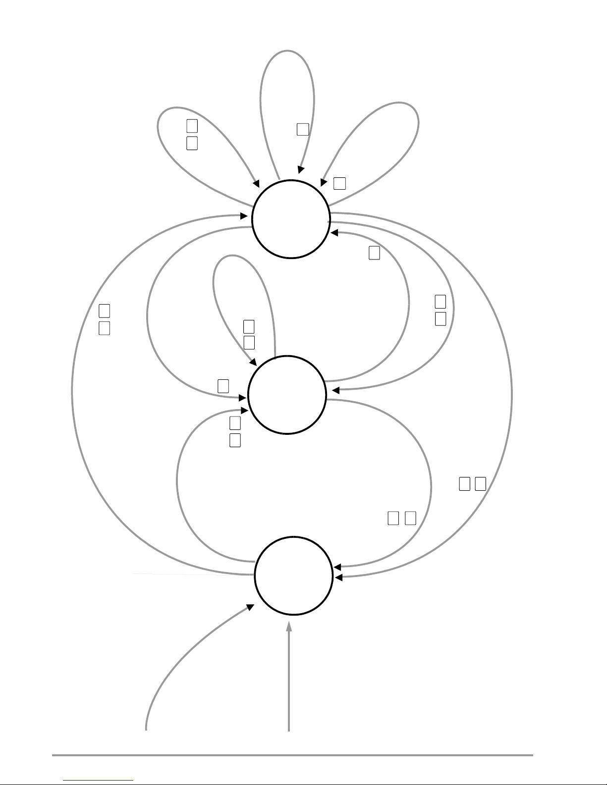
62 GMC-I Messtechnik GmbH
10.3 Sequence Status Diagram
SEQUENCE LED
OFF: SEQ. READY
ON: SEQ. HOLD
FLASHING: SEQ. RUN
S
T
A
R
T
(
1
s
t
VA
L
U
E)
S
T
EP
+
A
d
d
r
e
s
s
S
TA
R
T
(
1
.
W
E
R
T)
S
TE
P
+
A
d
d
r
e
s
s
C
O
N
T
(
C
O
N
T
I
N
UE
)
H
O
L
D
S
T
O
P
(
CUR
R
.
V
A
L
UE
)
S
T
O
P
(
F
I
N
A
L
V
A
L
UE
)
S
T
O
P
(
C
U
R
R
.
V
AL
U
E
)
ST
O
P
(
F
I
N
AL
V
A
L
U
E
)
G
O
(
1
s
t
V
A
L
U
E
,
…
)
C
O
NT
+
A
d
d
r
es
s
G
O
(
1
s
t
V
A
L
U
E
,
…
)
CO
N
T
+
A
d
d
r
e
s
s
G
O
(
1
s
t
V
A
L
U
E
,
…
)
STEP (NEXT)
B
AC
K
S
T
E
P
(P
R
E
V
.
)
SEQUENCE run (STOP)
p
o
n
ESC
ESC
0
0
MENU
MENU
READY
RUN
HOLD
(PAUSE)
HOT
KEY
HOT
KEY
HOT
KEY
Page 63
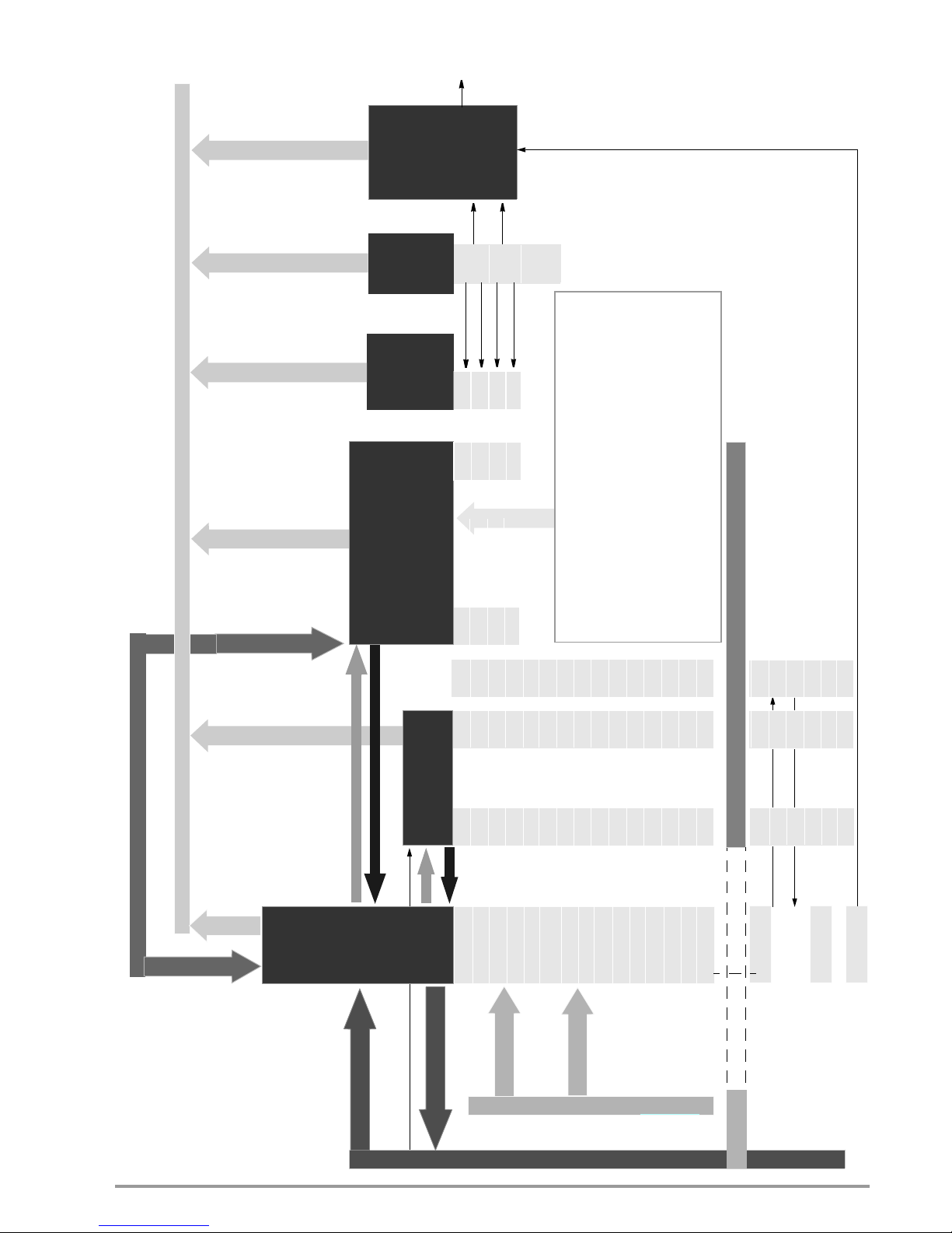
GMC-I Messtechnik GmbH 63
10.4 Memory Structure
Setting / Actual Value Query
Setpoint specification
REPETITION
STOP
START
TDEF
MINMAX
OCP
OVSET (OVP)
IL_H
UL_H
OUTPUT
TSET
ISET
USET
SETUP
Memory
Min-Max
Meas. Value
Memory
Current
Measured
Default Device Settings
#15
UMAX
UMIN
IMAX
IMIN
UOUT
IOUT
POUT
UOUT > UMAX
UOUT < UMIN
IOUT > IMAX
IOUT < IMIN
*SAV n
*RCL n
SM_LOAD n 1)
Sequence Memory
STORE? n
e.g. USET w
e.g. USET?
STORE n,w1,w2,w3,txt
Mains power on & Pon rcl / SbY
*RST
Mains power on & Pon rSt
Mains power off
SM_STORE n
Active
Device
Setting
n = 1 ... 12
/ 15
n = 1 ... 1536
/ 1700
e.g. UMAX?
e.g. UOUT?
T_MODE
Manual editing
SEq_c n Clear contents of memory location n (CLR)
SEq_c St-SP Clear memory contents from start to stop address (CLR)
SEq_r n
Content of memory location n is cleared between start and stop addresses,
memory locations up to stop address are reset
(n -> n-1), an empty memory location is inserted at the stop address (CLR)
SEq_i n Empty memory location n inserted between start & stop addresses
memory locations up to stop address are added up
(n -> n+1), the previous stop address memory location
is deleted
FSET
DISPLAY
UI_C_SET
e.g. *LRN? n
Tolerance Band
Function
(MINMAX=ON)
U
OUT
>UI_C_SET (W2)
U
OUT
<UI_C_SET (W1)
I
OUT
>UI_C_SET (W4)
I
OUT
<UI_C_SET (W3)
e.g. CRB?
ISET
TSET
FSET
USET
#1
*RCL99
(autom.)
3)
1
Or execution of a sequence function2 If appropriately configured with “SIG123 ...”3 After *RST, *RCL n
SIG x 2)
Main On & Pon r01 ... r12
/ 15
#99
undo
Non-Volatile Memory Range
ISET
TSET
FSET
USET
(MINMAX=ON)
Values
Page 64

64 GMC-I Messtechnik GmbH
11 System Messages
Procedures and entries are monitored in order to provide the user
with support.
The device is capable of detecting and reading out a great variety
of defective procedures.
In the case of manual operation, the error appears directly at the
display for a brief period of time. In addition to this, the last error
message can be viewed with the help of the appropriate menu
function.
Err appears at the left-hand display, and the three digit error code
at the right-hand display.
In the case of operation with a PC, the last three error messages
can be accessed by executing the ERROR? command (see
ERROR? command in the section entitled “Descriptions of Operating Commands”.
Code
Err...
Meaning / Cause Remedy
00 No error
01 TYPE (BZ) detection For internal production process only
05 UNKNOWN KEYCODE, or in case of “LCL LOCKED”, [ESC] has been briefly
activated for enabling
12 CMD buffer overflow Overflow at internal CMD buffer
21 USET, ISET, PSET (parameter error)
22 UL,IL (parameter error)
29 DDTE *DDT command string > 80 characters or ?*TRG? within *DDT ...
31 CME command error General
32 EXE execution error General
Interface
51 RS 232, PB, parity bit
52 RS 232, SB, stop bit
53 PB + SB, RS 232
54 RS232, FRAME OVERFLOW (impermissible combination DB/PB/SB) Only occurs during manual configuration
55 Active talker state but no listener present Only possible with IEEE 488 interface option
56 IEC$LATA$ERR (active listener and active talker) Only possible with IEEE 488 interface option
61 ADJUST parameter error
62 ADJUST order impermissible (REMOTE)
63 [U/I]-OFFSET/FULL SCALE -> (!) [CV/CC] MODE Corresponding operating mode required!
64 ADJUST LIMITs or OFFSET (MEASUREMENT NEGATIVE or OVERFLOW)
66 CALIBRATION ERROR/EXIT (-> UNCAL)
69 MEMORY DATA (-> ERROR) ?) Faulty data, possible cause: low battery
71 Table values (#): USET<UL_L, USET>UL_H, ISET<IL_L, ISET>IL_H Limit error during sequence execution
73 OUTE: “OUTPUT ON” =/= Tx MODE “OUT” & Tx-SIG “OUT OFF” Trigger mode power output and signal blocked (=OFF!)
74 TRGE: “MINMAX ON” =/= Tx MODE “MIN” & Tx-SIG “MINMAX OFF” Min-max control for the trigger mode and signal blocked (=OFF!)
75 TRGE: “SEQUENCE ON” =/= Tx MODE “SEQ” & Tx-SIG “SEQUENCE STOP” Sequence control for the trigger mode and signal blocked (=OFF!)
76 TRGE: “ANALOG INP” =/= Tx MODE “AI?” & Tx-SIG (UEXT,IEXT) Uext, Iext control for the trigger mode and signal blocked (=ON!)
81 RCL n (no data): SETUP memory n: invalid or no data
82 START -> STOP - INVALID VALUES
83 START-ADR > STOP-ADR
84 Not (STOP_ADR < MEM < START_ADR) or SUBSEQUENCE (cond.) Address range or storage address is out of actual start-stop-address range or is an active sub-
sequence. Specify the sequence range for delete and repeat command.
85 CONTINUE (no initialization, status =/= “HALT”)
86 SUBSUBSEQUENCE impermissible
89 “SEQUENCE OFF” required for current command
91 SELFTEST (*TST?)
96 MIN LIMIT UNDERFLOW, direct entry of a numerical value requires > UL_L and/or > IL_L
93 Current command not permissible for power control! Impermissible combination of functions
96 MIN LIMIT UNDERFLOW Numerical direct entry of a numerical value > UL_L and/or > IL_L necessary
97 MIN LIMIT UNDERFLOW
98 MAX LIMIT OVERFLOW
99 OVERLOAD / OVERFLOW
Page 65

GMC-I Messtechnik GmbH 65
RSTSRC (RESET SOURCE REGISTER):
Description / Text per Data Sheet no. C8051F122
DISPLAY Meaning/Cause Remedy
left right
Err PFC PFC Error Inadequate/unstable line voltage or device error, not ready for operation, device controls
disabled, shutdown (OUTPUT OFF)
Err AC-H Change from AC-LOW to AC-HIGH Transition from the „lower“ line voltage range (= status after power ON) AC_L to the „upper“
range AC_H generates message „ERR AC-H“.
Please note: Pnom value is not automatically raised in the process! A new „Power ON“ is required for this purpose, including:
– automatic RESET (parameter setting: „POWER_ON RST“) or
– subsequent „RESET“ (manual operation/interface) or
– Recall of a suitable SETUP memory
(which has not been saved under power derating conditions!)
(Pnom is the reference quantity for the PSET function!)
Err AC-L Change from AC-HIGH to AC-LOW up to and including firmware 004:
Transition from the „upper“ line voltage range to the „lower“ range generates message
„ERR AC-L“ and results in a shutdown if no power derating has been active (operation disabled, „Power ON“ required!)
Transition from the „upper“ line voltage range AC_H to the „lower“ range AC_L
generates message „ERR AC-L“ without shutdown if power derating has already been active.
as from firmware 005:
Transition from the „upper“ line voltage range to the „lower“ range generates the message
„ERR AC-L“ and results in power derating,
as long as the status „AC LOW“ „lower“ line voltage range applies. Upon reversal of the line
voltage to the „upper“ line voltage range (status „AC HIGH“), the power derating is cancelled.
Err AC-F AC-FAIL Inadequate/unstable line voltage or device error, not ready for operation, device controls
disabled, shutdown (OUTPUT OFF)
as from firmware 010:
Temporary deactivation for the purpose of device protection.
If insufficient/instable line voltage is present or a device error occurs, the instrument shuts
down (OUTPUT OFF) and is not ready for operation during this time.
After approximately 0.25 s, an automatic restart is performed by the instrument in accordance
with the settings for POWER_ON (standby, reset, recall).
D7 (80H): RESERVED
D6 (40H): CNVRSEF: (CONVERT START 0 RESET SOURCE FLAG)
D5 (20H): CORSEF: (COMPARATOR 0 RESET FLAG)
D4 (10H): SWRSF: SOFTWARE RESET FLAG
D3 (08H): WDTRSF: WATCHDOG TIMER RESET FLAG
D2 (04H): MCDRSF: MISSING CLOCK DETECTOR FLAG
D1 (02H): PORSF: POWER-ON RESET FLAG
D0 (01H): PINRSF: HW PIN RESET FLAG
Page 66

66 GMC-I Messtechnik GmbH
12 Operating Software
Comprehensive operating software is provided for the SYSKON
Konstanter (on the included CD-ROM, or can be downloaded
from our website).
The software is started by running the EXE file; no further
installation is required.
The software detects devices which are connected to the various
possible interfaces including USB, RS 232 and GPIB. Devices
detected by the software are identified and can be selected. If
more than one device is connected, the software can be started
several times in order to operate them.
The activated device logs on via the soft front panel and is thus
unequivocally recognized.
Page 67

GMC-I Messtechnik GmbH 67
Sub-menus
Further operation can be carried out as shown in the figures.
Basic panel Advanced panel
Sequence panel Configuration panel
Task panel Command panel
Page 68

68 GMC-I Messtechnik GmbH
Page 69

GMC-I Messtechnik GmbH 69
13 Index
C
Control Mode Query
PC Query
. . . . . . . . . . . . . . . . . . 47
D
Device Settings
Current Settings
Query from PC . . . . . . . . . . . 40
Save
Via PC
. . . . . . . . . . . . . . 42
From Setup-Sequence Memory
Accept
Via PC
. . . . . . . . . . . . . . 41
Reset
Via PC
. . . . . . . . . . . . . . . . . 41
Transfer to / Query from Sequence Memory
Via PC . . . . . . . . . . . . . . . . . 53
Digital Displays
Switch On and Off via PC
. . . . . . 44
I
Interface
Installation . . . . . . . . . . . . . . . . . . . 6
Parameter Setting
. . . . . . . . . . . . 26
Technical Data . . . . . . . . . . . . . . . . 7
M
Min-Max Memory
Display
Via PC
. . . . . . . . . . . . . .46, 55
Edit
Via PC
. . . . . . . . . . . . . . . . . 47
O
Operating Commands
List of Setting Commands . . . . . . 58
Output Current
Measured Value
PC Query
. . . . . . . . . . . . . . . 46
Setpoint
Via PC
. . . . . . . . . . . . . . . . . 47
Setting Limit
Via PC . . . . . . . . . . . . . . 46, 54
Output Power
PC Query
. . . . . . . . . . . . . . . . . . 50
Output Switching stazs
Response at Power On
Via PC
. . . . . . . . . . . . . . . . . 50
Output Swithing Status
Switch/Query
Via PC
. . . . . . . . . . . . . . . . . 49
Output Voltage
Measured Value
PC Query
. . . . . . . . . . . . . . . 55
Setpoint
Via PC
. . . . . . . . . . . . . . . . . 55
Overcurrent Protection
Activate/Deactivate
Via PC
. . . . . . . . . . . . . . . . . 48
Q
Query Device ID . . . . . . . . . . . . . . . . . 40
R
RESET . . . . . . . . . . . . . . . . . . . . . . . . 39
Response after Power On with Varying Line Voltage Ranges
8
S
Self-Test via PC . . . . . . . . . . . . . . . . . . 42
Sequence
Control
Via PC
. . . . . . . . . . . . . . . . . 51
Dwell Time
Memory Location Independent
Via PC
. . . . . . . . . . . . . . 53
Memory Location Specific
Via PC . . . . . . . . . . . . . . 54
Repetitions
Via PC
. . . . . . . . . . . . . . . . . 51
Start Address
Via PC
. . . . . . . . . . . . . . . . . . . . . 53
Status and Event Management
Clear Event Register . . . . . . . . . . . 39
Device Clear Function
. . . . . . . . . 44
Enable Registers
. . . . . . . . . . . . . 40
Event Register Query
. . . . . . . . . . 40
Individual Status Query
. . . . . . . . . 40
Operation Complete Query . . . . . 41
Power-On Status Clear Query . . . 41
Status Byte Register Query
. . . . . 42
Status Register Query . . . . . . . . . 44
Wait to Continue . . . . . . . . . . . . . 42
Stop Address
Via PC
. . . . . . . . . . . . . . . . . . . . . 53
System Messages, Error Messages
. . . 64
T
Trigger Digital
Define Device Trigger . . . . . . . . . . 39
Trigger . . . . . . . . . . . . . . . . . 42
Trigger Response
Edit
Via PC
. . . . . . . . . . . . . . . . . 54
W
Waiting Time . . . . . . . . . . . . . . . . . . . . 55
Page 70

70 GMC-I Messtechnik GmbH
14 Order Information
Software
Further information regarding operating software and drivers is
available for download on the internet:
http://www.gossenmetrawatt.com
Accessories
15 Repair and Replacement Parts Service
Calibration Center* and Rental
Instrument Service
If required please contact:
GMC-I Service GmbH
Service Center
Thomas-Mann-Str. 20
90471 Nürnberg, Germany
Phone: +49 911 817718-0
Fax: +49 911 817718-253
e-mail service@gossenmetrawatt.com
www.gmci-service.com
This address is only valid in Germany. Please contact our
representatives or subsidiaries for service in other countries.
* DAkkS Calibration Laboratory for Electrical Quantities
D-K-15080-01-01 accredited per DIN EN ISO/IEC 17025
Accredited quantities: direct voltage, direct current value, direct current resistance,
alternating voltage, alternating current value, AC active power, AC apparent power,
DC power, capacitance, frequency, temperature
Competent Partner
GMC-I Messtechnik GmbH
is certified in accordance with
DIN EN ISO 9001.
Our DAkkS calibration laboratory is accredited by the Deutsche
Akkreditierungsstelle GmbH (National accreditation body for the
Federal Republic of Germany) in accordance with DIN EN ISO/IEC
17025 under registration number D-K-15080-01-01.
We offer a complete range of expertise in the field of metrology:
from test reports and factory calibration certificates, right on up to
DAkkS calibration certificates.
Our spectrum of offerings is rounded out with free test equipment
management.
Our service department includes an on-site DAkkS calibration bench.
If errors are discovered during calibration, our specialized personnel are capable of completing repairs using original replacement
parts.
As a full service calibration lab, we can calibrate instruments from
other manufacturers as well.
16 Product Support
If required please contact:
GMC-I Messtechnik GmbH
Product Support Hotline
Phone: +49 911 8602-0
Fax: +49 911 8602-709
e-mail: support@gossenmetrawatt.com
17 Manufacturer’s Guarantee
The SYSKON Konstanter is guaranteed for a period of 2 years
after shipment. The manufacturer’s guarantee covers materials
and workmanship. Damages resulting from use for any other than
the intended purpose, as well as any and all consequential damages, are excluded.
Calibration is guaranteed for a period of 12 months.
Description (abbreviated name) Article Number
SYSKON P500-060-030 SYSTEM KONSTANTER K346A
SYSKON P800-060-040 SYSTEM KONSTANTER K347A
SYSKON P1500-60-60 SYSTEM KONSTANTER K353A
SYSKON P3000-060-120 SYSTEM KONSTANTER K363A
SYSKON P4500-060-180 SYSTEM KONSTANTER K364A
Option IEEE 488 interface for SYSKONKONSTANTER K384A
Description Note Article No.
RS 232 bus cable, 2 m For connecting a device to an
RS 232 interface (extension cable, 9-pin
socket / 9-pin plug connector)
GTZ32410
00R0001
Page 71

GMC-I Messtechnik GmbH 71
Page 72

Edited in Germany • Subject to change without notice • PDF version available on the Internet
GMC-I Messtechnik GmbH
Südwestpark 15
90449 Nürnberg •
Germany
Phone +49 911 8602-111
Fax +49 911 8602-777
E-Mail info@gossenmetrawatt.com
www.gossenmetrawatt.com
 Loading...