

Page 1
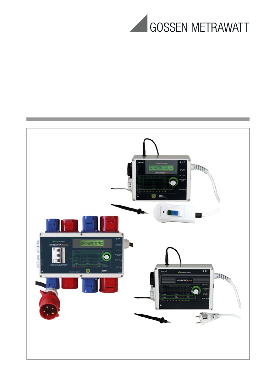
Operating Instructions
MINITEST⏐MASTER⏐PRO⏐BASE
Testers per DIN VDE 0701-0702
3-349-358-15
8/5.16
Page 2
11
6
4
12
5
1
9
8
2
3
7
1
0
13
23
24
18171615
22212019
9
8
1
2
3
14
10
4
5236
11
2 GMC-I Messtechnik GmbH
Page 3
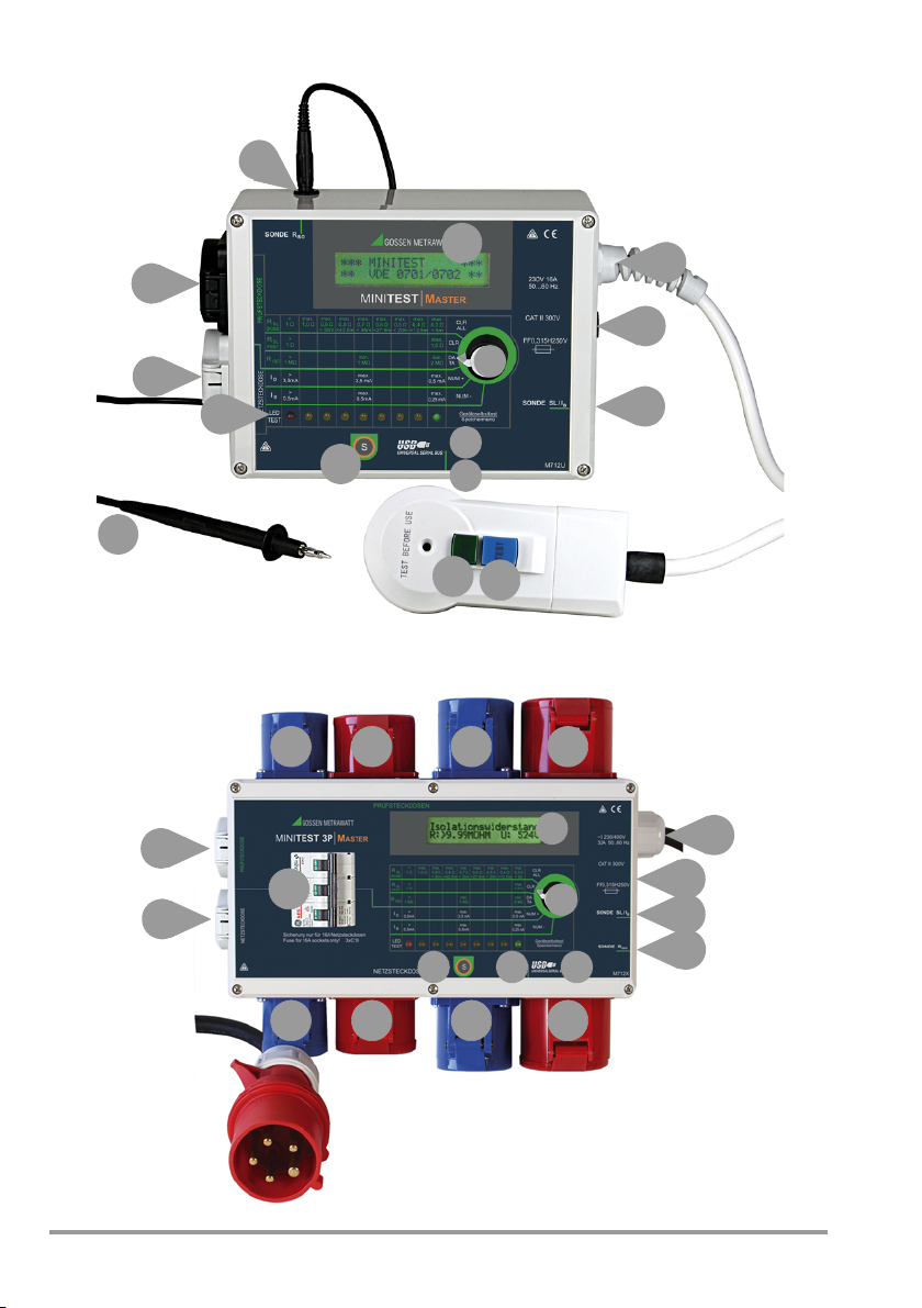
1 Mains power cable
2 Fuse (for protecting the probe (3))
3 Probe connector socket for measuring
protective conductor current (PE) or
contact current (I
)
C
4 Rotary switch for selecting the desired
measuring function
5USB port *
6 Send key * for data transmission or
storage
7 LEDs for indicating adherence to, or
violation of limit values
8 Earthing contact mains outlet
9 Earthing contact test socket
10 Probe connector socket for insulation
resistance measurement
(only necessary for Safety Class II)
11 LCD *
12 POWER ON key *
13 RCCB test/POWER OFF key *
14 Fuse for 16 A mains outlets
and mains switch
15 CEE test socket 1P+N+PE 16 A-6h
16 CEE test socket 3P+N+PE 16 A-6h
17 CEE test socket 1P+N+PE 32 A-6h
18 CEE mains socket 3P+N+PE 32 A-6h
19 CEE mains socket 1P+N+PE 16 A-6h
20 CEE mains socket 3P+N+PE 16 A-6h
21 CEE mains socket 1P+N+PE 32 A-6h
22 CEE mains socket 3P+N+PE 32 A-6h
23 Barcode scanner connection
(9-pin, subminiature plug) **
24 Probe cable
*not for MINITEST Base
** MINITEST Master and MINITEST 3P Master only
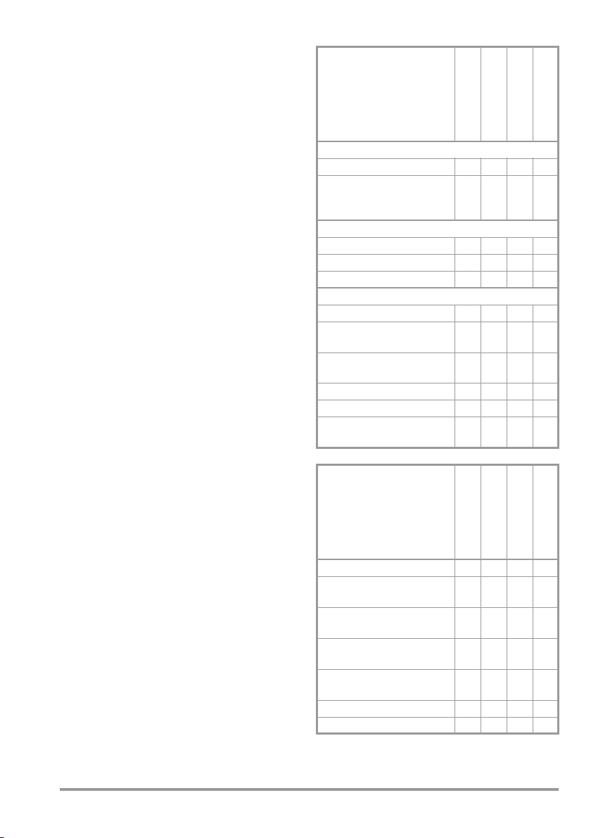
Features of MINITEST...
series
MINITEST 3P Master
MINITEST Master
Connection types
Tests on monophase DUTs
Tests on 3-phase DUTs
via additional test sockets
CEE 16A / CEE 32A
Fusing devices
Fuse for probe connection
RCCB in mains plug
Miniature circuit breaker
Report functions
Illuminated two-line LCD *
Memory for 2,000 tests
(10 measured values per test)
Key for transmission of
measured values
Key for storing measured values
Data interface (USB port)
Barcode scanner connection
(9 pin, subminiature plug)
* as from series launched in March 2007
Standard equipment
accessories of MINITEST... series
Probe cable with test probe
Adapter for earthing contact plug to
CEE coupling 3P+N+PE 32 A-6h
Adapter for plug 1P+N+PE 16 A
to CEE coupling 3P+N+PE 32 A-6h
Adapter for plug 3P+N+PE 16 A to
CEE coupling 3P+N+PE 32 A-6h
Adapter for plug 1P+N+PE 32 A to
CEE coupling 3P+N+PE 32 A-6h
USB connector cable
Operating instructions
✘✘✘✘
✘ –––
✘✘✘✘
– ✘✘ –
✘ –––
✘✘✘ –
✘✘ ––
✘✘✘ –
✘✘ ––
✘✘✘ –
✘✘ ––
MINITEST 3P Master
MINITEST Master
✘✘✘✘
✘ –––
✘ –––
✘ –––
✘ –––
✘✘✘ –
✘✘✘✘
MINITEST Pro
MINITEST Base
MINITEST Pro
MINITEST Base
GMC-I Messtechnik GmbH 3
Page 4

Table of Contents
Attention!
!
Attention!
!
1 Applications ...............................................4
2
Safety Features and Precautions .......................4
3 Initial Start-Up ............................................6
4 Test Sequence ...........................................6
Descriptions of Individual Measurements .........8
5
5.1 Measurements at the Test Outlet(s) ........................8
5.2 Measurements at the Mains Outlet(s) .....................9
6 Report Functions ......................................10
6.1 Transmission Mode .............................................10
6.2
Permanent Transmission ......................................... 10
6.3
Memory Mode ........................................................ 10
6.3.1 Activate Memory Menu .......................................10
6.3.2 Selecting Memory Function .................................10
6.3.3 Exiting the Memory Menu ....................................11
6.3.4 Reading out Stored Measured Values
at the PC ............................................................11
6.3.5 Barcode Scanner Function ...................................11
6.3.6 Switching Off Safely ............................................11
7 Technical Data .........................................12
8 Maintenance ............................................14
8.1 Housing .............................................................14
8.2 Replacing the Fuse .............................................14
8.3 Recalibration ......................................................14
8.4
Return and Environmentally Sound Disposal .................. 15
9 Accessories ..............................................15
9.1 Standard Equipment ...........................................15
9.2 Order Information for Available
Accessories ........................................................15
10 Repair and Replacement Parts Service
Calibration Center
and Rental Instrument Service
...................16
11 Product Support .......................................16
1 Applications
The test instrument is used to test the electrical safety of monophase and 3-phase
electrical devices. The test instrument allows
for the measurement of protective conductor
resistance, insulation resistance and differential current and/or contact current in
accordance with DIN VDE 0404.
2 Safety Features and Precautions
The test instrument has been manufactured
and tested in accordance with the following
safety regulations:
IEC 61010-1 / DIN EN 61010-1 / VDE 0411-1,
IEC 61557-2/-4 / DIN EN 61557-2/-4 /
DIN VDE 0413-2/-4
When used for its intended purpose, the
safety of the user, the test instrument and
the device under test (electrical equipment
or electrical medical device) is assured.
Read the operating instructions carefully and
completely before placing your test instrument
into service. Follow all instructions contained
therein. Make sure that the operating instructions
are available to all users of the instrument.
Tests may only be performed by a qualified
electrician, or under the supervision and
direction of a qualified electrician. The user
must be instructed by a qualified electrician
in the execution and evaluation of tests.
Safety Precautions for MINITEST 3P Master
The instrument is intended for connection
with a 3-phase system up to 32 A.
MINITEST 3P Master
customary CEE and earthing contact outlets via
the adapters included in the standard equipment.
can also be connected to all
The instrument may only be connected to the mains via the adapters
included in the standard equipment.
All mains sockets and/or test sockets
are connected in parallel:
Only one DUT at a time may therefore be
connected to a socket.
4 GMC-I Messtechnik GmbH
Page 5
Observe the following safety precautions:
!
• MINITEST Master / Pro / Base:
The instrument may only be connected
to electrical supply systems with 230 V/
240 V which conform to the valid safety
regulations (e.g. IEC 60364, VDE 0100)
and are protected with a fuse or circuit
breaker with a maximum rating of 16 A.
• Measurements within electrical systems
are prohibited.
• Be prepared for the occurrence of
unexpected voltages at devices under
test (for example, capacitors may be
dangerously charged).
• Make certain that the measurement
cables are in flawless condition, e.g. no
damage to insulation, no cracks in
cables or plugs etc.
• Insulation Resistance Measurement R
Testing is conducted with up to 500 V.
Current limiting is utilized (I < 3.5 mA),
but if the terminals (L or N) are touched,
electrical shock may occur which could
result in consequential accidents.
• Differential Current Measurement I
Contact Current Measurement I
It is absolutely essential to assure that
the device under test is operated with
line voltage during performance of the
differential current and/or contact current
measurement. Exposed conductive
parts may conduct dangerous contact
voltage during testing, and may not
under any circumstances be touched
(MINITEST Master / Pro:
mains power is disconnected if leakage
current exceeds approx. 15 mA).
• The function test may only be performed
after the device under test has
successfully passed the safety test while
connected to the test socket!
ISO
/
D
C
Opening of Equipment / Repair
The equipment may be opened only by
authorized service personnel to ensure the
safe and correct operation of the equipment
and to keep the warranty valid.
Even original spare parts may be installed
only by authorized service personnel.
In case the equipment was opened by unauthorized personnel, no warranty regarding
personal safety, measurement accuracy,
conformity with applicable safety measures
or any consequential damage is granted by
the manufacturer.
The measuring and test instrument may not be used:
• if it demonstrates visible damage
• with damaged connector cables and
measuring cables
• if it no longer functions properly
• after extraordinary stresses due to transport
• MINITEST 3P Master: with other adapters
than those included in the standard
equipment.
In such cases, the instrument must be
removed from operation and secured
against unintentional use.
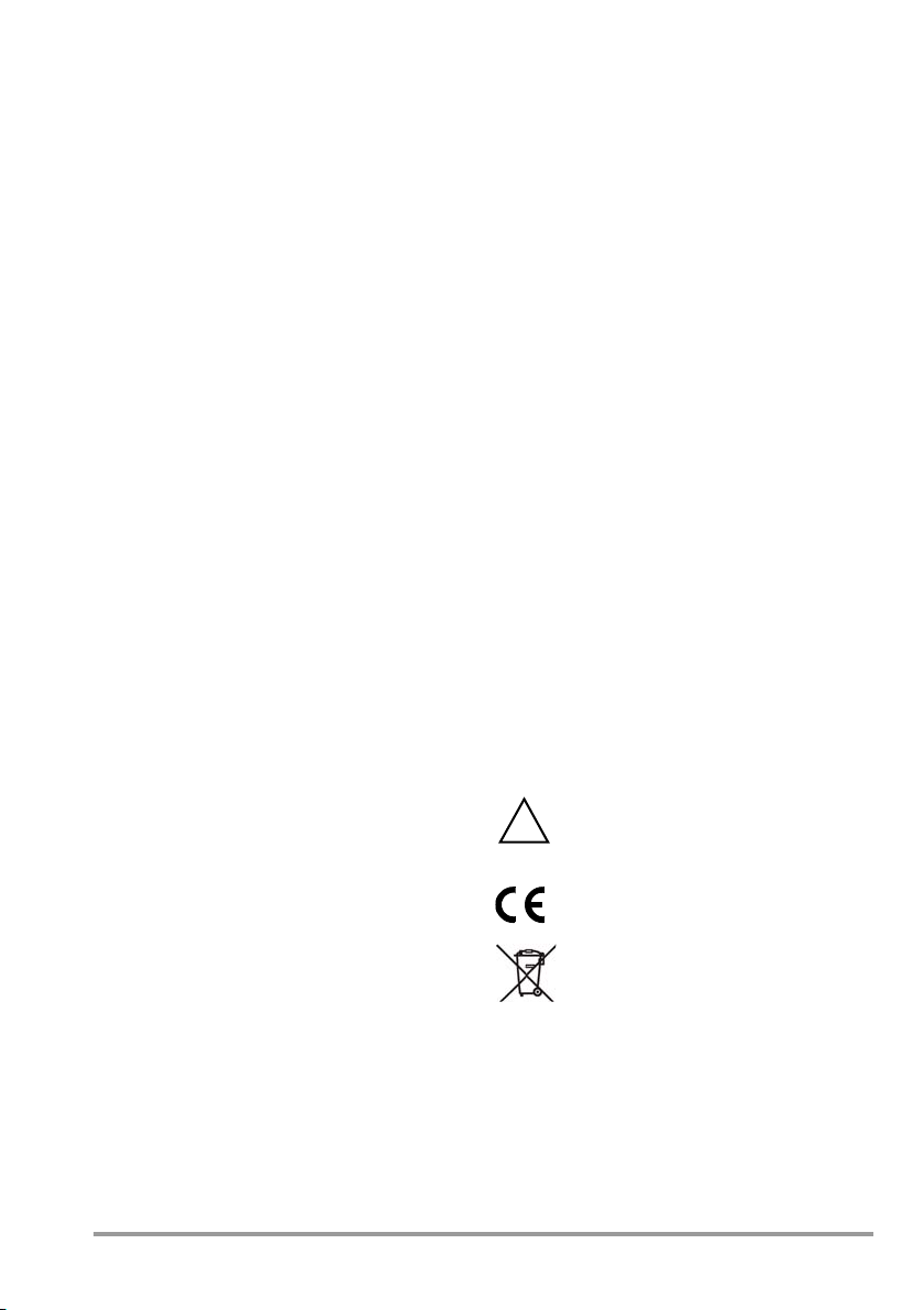
Meanings of Symbols on the Instrument
The symbols on the instrument have the
following meanings:
Warning concerning a point of
danger (attention: observe
documentation!)
Indicates EC conformity
The device may not be disposed
of with the trash. Further information regarding the WEEE mark
can be accessed on the Internet
at www.gossenmetrawatt.com
by entering the search term
WEEE.
GMC-I Messtechnik GmbH 5
Page 6
3 Initial Start-Up
Connection
Connect the test instrument’s mains plug to
the mains power outlet.
MINITEST 3P Master:
The instrument can be connected to all cus-
tomary CEE sockets by means of the mains
connection adapter (standard equipment).
Switching the MINITEST 3P Master On:
The instrument is switched on via the 3-pole
miniature circuit breaker (m.c.b.).
Switching the MINITEST Master / Pro / Base On
The test instrument can be switched on with
the green power-on switch located on the
integrated residual current protective device.
It can be switched back off again with the
blue test key.
Switching the MINITEST Base On
The test instrument is switched on and off
with the help of the mains plug.
4 Test Sequence
Testing for electrical safety always begins
with a visual inspection. The measurements
are then conducted in the order in which
they appear next to the selector switch on
the test instrument, from top to bottom.
For each type of measurement, the test
instrument evaluates the measured values
and indicates whether or not limit values in
accordance with DIN VDE 0701-0702 have
been adhered to by means of an LED array.
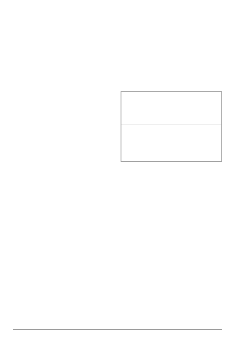
Indication Meaning
Green
LED
Red
LED
Yel lo w
LED
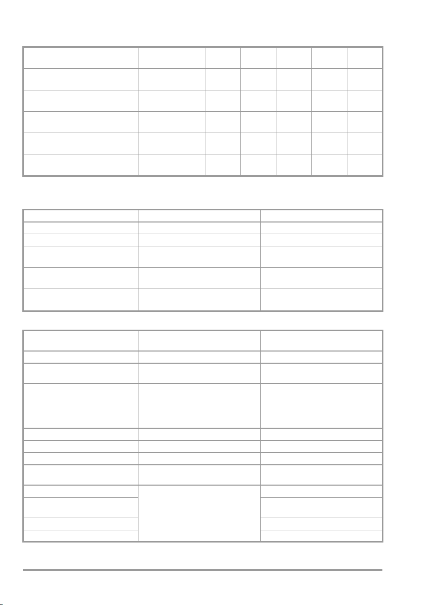
The number and type of required measurements are determined according to the classification of the device under test:
The measured value is better than the
strictest limit value.
The measured value is worse than the most
lenient limit value.
The limit value is in-between the strictest
and the most lenient limit values. Whether
or not the DUT passes testing depends upon
the device’s classification.
Evaluation should be conducted by a
qualified electrician.
6 GMC-I Messtechnik GmbH
Page 7

Connect DUT to the test socket.
Protective
Device Under Test
All exposed
parts are connected with PE
With exposed
parts which
are not connected with PE
Earth contact plug
All exposed
Safety class I
parts are connected with PE
With exposed
parts which
are not connected with PE
CEE plug *
Permanently
connected DUT
With European
earth contact plug
Safety class II
* MINITEST 3P Master only
conductor
resistance
Probe socket
PE/ I
Connect DUT to mains outlet.
– Switch the DUT on.
Protective
conductor
resistance
Permanent,
C
probe socket
PE/ I
C
Insulation
resistance
No probe
required
Insulation
resistance
Probe
socket R
ISO
Differential
current
No probe
required
Contact current
Probe socket
PE/ I
C
✘
✘
Test with the
mains plug
poled in both
directions.
✘
Test with the
mains plug
poled in both
directions.
✘
Test with the
mains plug
poled in both
directions.
✘✘
✘✘✘
✘
?
✘✘
✘✘
✘
✘
Test with the
mains plug
poled in both
directions.
Use of mains outlet number depending on the mains terminal
(all test sockets as well as mains outlets No. 8 and 19 can always be used
regardless of which mains adapters are used)
Mains connection with mains plug 3P+N+PE 32 A
Connection with earthing contact plug adapter to CEE coupling 3P+N+PE 32 A-6h
Connection with adapter for plug 1P+N+PE 16 A to CEE coupling 3P+N+PE 32 A-6h
Connection with adapter for plug 3P+N+PE 16 A to CEE coupling 3P+N+PE 32 A-6h
Connection with adapter for plug 1P+N+PE 32 A to CEE coupling 3P+N+PE 32 A-6h
GMC-I Messtechnik GmbH 7
Mains outlet number
20 21 22
✘✘✘
–
–
✘
– ✘ –
✘
max. 16 A
✘
max. 16 A
✘
max. 16 A✘max. 16 A
–
–
Page 8

5 Descriptions of Individual Measurements
Attention!
!
Attention!
!
Attention!
!
5.1 Measurements at the Test Outlet(s)
Protective Conductor Resistance, R
SOCKET
PE
The probe must be plugged into the
PROBE PE/I
socket for the measurement of
C
protective conductor resistance. Measurement is performed between the protective
conductor terminal at the test outlet and the
PROBE PE/I
Protective Conductor Resistance, R
socket.
C
FIX
PE
This measurement is used for testing the
protective conductor at permanently connected devices. The test instrument must be
connected to the same supply circuit as the
device under test during measurement.
Good test results may be obtained
with parallel ground connections,
although the protective conductor is
interrupted.
The probe must be plugged into the
PROBE PE/IC socket for the measurement of
protective conductor resistance. Measurement is performed between the protective
conductor terminal at the mains connection
and the PROBE PE/I
socket.
C
Testing is performed up through a resistance
value of approximately 1.3 Ω with automatic
polarity reversal.
The earthing contact resistance and the test
current are indicated on the LCD (not for
MINITEST Base).
Checking the Zero Point and the Fuse
The zero point and the internal fuse can be
checked by inserting the plug attached to
the test probe cable into the PROBE R
ISO
socket and the tip of the test probe into the
PROBE PE/IC socket with the selector switch in
SOCKET or RPE FIX setting. The dis-
the R
PE
played value should not exceed 100 mΩ.
Note: If a current of 0 mA is indicated, the
fuse is usually defective. Test and replace it,
if required.
It is absolutely essential to insert the
tip of the test probe into the
PROBE PE/IC socket for this test!
Use only the probe cable which is
included with the test instrument. If a
different probe cable is used:
– The measured value may be
distorted.
– The test instrument may be
damaged.
– Malfunctioning may occur.
Insulation Resistance, R
ISO
Various test types are provided for the measurement of insulation resistance.
The test type is selected automatically when
the test probe is plugged into the probe
connector socket (10).
The original test probe cable must be used
in order to take advantage of this function.
Test type switching cannot be assured if
other test probe cables are used.
• For safety class I DUTs without exposed
conductive parts:
Test insulation between L/N and PE at
the test outlet.
The test probe cable may not be plugged into
the PROBE R
socket for this test!
ISO
• For safety class II DUTs, or for safety
class I DUTs with exposed conductive
parts which are not connected to the
protective conductor:
Test between L/N at the test outlet and
the PROBE R
socket.
ISO
The test probe must be plugged into the
PROBE R
socket for this test!
ISO
The insulation resistance and the test voltage are indicated on the LCD (not for
MINITEST Base).
8 GMC-I Messtechnik GmbH
Page 9

Discharging the Device Under Test
Attention!
!
Note!
The device under test is automatically
discharged when the insulation test is
switched off (turn switch to R
or ID).
PE
The LEDs light up rapidly, one after the other
from left to right, during discharging.
Furthermore, residual voltage appears at the
display (not for MINITEST Base).
Leave the DUT connected to the test
instrument during the discharging sequence.
5.2 Measurements at the Mains Outlet(s)
Differential current and/or contact current
measurements are performed at the mains
outlet(s). The DUT must be unplugged, and
plugged back in again. In the case of mains
plugs which are not polarity protected, testing
must be conducted with the mains plug poled in
both directions.
The mains outlet(s) always conduct(s) voltage as soon as the test instrument has been switched on.
Make sure that the device under test
is switched off before plugging it into
the mains outlet.
The device under test must be switched on during
testing.
The device under test must be switched
back off before it is unplugged from the
mains outlet.
Differential Current Measurement, I
D
Total current from all phase conductors is
measured during differential current measurement. For safety class I devices, this
corresponds to the amount of current which
is conducted by the protective conductor.
Differential current is displayed in mA at the
LCD (not for MINITEST Base).
Evaluating the Measured Values
Measured values of less than 0.5 mA are
indicated by means of a green LED.
Measured values of greater than 3.5 mA are
indicated by means of a red LED. These
devices may be dangerous, however, for
example for 3-phase current devices, there may
be higher admissible limit values of e.g. 1 mA per
kW up to 10 mA, depending on the manufacturer’s specifications. These cases are all indicated with the red LED. Evaluation must be
conducted by a qualified electrician in this
case.
Measured values of between 0.5 and 3.5 mA
are indicated by means of a yellow LED. An
evaluation of electrical safety should be conducted by a qualified electrician in this case.
Contact Current Measurement, I
C
When measuring contact current, current is
measured which is conducted via the probe
at the PROBE PE/I
socket to the protective
C
conductor terminal at the device under test.
Evaluating the Measured Values
Measured values of less than 0.25 mA are
indicated by means of a green LED. There is
no danger in touching these parts.
Measured values of greater than 0.5 mA are
indicated by means of a red LED. Devices
which demonstrate these values are
dangerous because persons who touch
them are startled, which may result in
consequential accidents.
These devices may not be placed back into
service.
Measured values of between 0.25 and
0.5 mA are indicated by means of a yellow
LED. Current within this range is not
dangerous, but the threshold of perception
is approximately 0.1 mA depending upon
sensitivity, which causes mild tingling. This is
unpleasant for some people, for which
reason devices of this sort should be
examined.
Self-Test
A device self-test is conducted when the
selector switch is turned to the LED Test
position.
Testing is indicated by the LEDs which light
up one after the other from left to right.
GMC-I Messtechnik GmbH 9
Page 10

6 Report Functions
Depending on the selected operating mode,
the measured values and the result of each
test can be transmitted to a PC via USB port
for onward processing or stored to the internal device memory. The transmission or
storage process of measured values is indicated by all LEDs lighting briefly up from
right to left.
Operating mode selected at the test
instrument
MINITEST 3P Master
MINITEST Master
MINITEST Pro
Transmission mode
(Transmission of individual measured values)
Permanent transmission
(Continuous transmission of measured values)
Memory mode
(Internal measured value memory)
Selection of Operating Mode
The corresponding PC analysis software
programs have to be installed and started for
the three different operating modes in order
to receive data, see table above.
Press key „S“ (6) when switching on the
instrument to set the requested operating
mode. The following operating modes are
shown in subsequent order:
• „Transmission mode“, siehe chapter 6.1
• „Permanent transmission“, see chapter 6.2
• „Memory mode“, see chapter 6.3
The operating mode which is indicated when
releasing key „S“ (6) is selected. This setting
remains active even after switching off the
instrument.
✘✘
✘
✘✘✘
✘✘—
6.1 Transmission Mode
To transmit the current measured value, key
„S“ must be pressed in operating mode
„Transmission mode“.
6.2 Permanent Transmission
If operating mode „Permanent transmission“
is activated, each measured value is transmitted via the USB port.
6.3
Memory Mode
In the test instruments MINITEST Master or
MINITEST 3P Master a maximum of 2,047
DUTs with 10 measured values per DUT can
be stored. If an attempt is made to store
more than 10 measured values for one DUT,
the additional values are ignored and the red
LED lights up briefly.
6.3.1 Activate Memory Menu
After selecting memory mode (see above) you
have to set the rotary switch to position
teselbsttest/Speichermenü (
ory Menu)
. Activate the memory menu by
Self-test/Mem-
pressing key „S“ (6). The following is shown on
the LCD:
** MEMORY MENU ** SELECTION -> SWITCH.
You may now select the requested memory
function via the rotary switch.
6.3.2 Selecting Memory Function
➭ Key NUM – > Menu DUT NUM –
The number of the current memory location
is reduced by one each time key „S“ (6) is
pressed. The lowest possible value is „1“.
The letter „D“ in front of the number signifies
that data are already available for this memory location.
➭ Key NUM + > Menu DUT NUM+
The number of the current memory location
is increased by one each time key „S“ (6) is
pressed. The highest possible value is
„2,047“, i.e. a maximum of 2,047 DUTs can
be tested. The letter „D“ in front of the number signifies that data are already available
for this memory location.
Gerä-
10 GMC-I Messtechnik GmbH
Page 11

➭ Key DATA > Menu MEASURED VALUE NO.
In this switch position all measured values of
a DUT are shown in a consecutive, numerical sequence in the order of their recording.
➭ Key CLR > Menu DUT DEL ?
Pressing key „S“ (6) deletes the current
memory location, i.e. all data for the selected
DUT. As a preventive measure against accidental deletion you have to keep key „S“ (6)
pressed for about half a second before the
deletion process is started. The red LED
lights up during the deletion.
➭
Key CLR ALL > Menu DELETE MEMORY ?
Pressing key „S“ (6) deletes the entire device
memory. As a preventive measure against
accidental deletion you have to keep key „S“
(6) pressed for about 1 to 2 seconds before
the deletion process is started. The red LED
lights up during the deletion.
6.3.3 Exiting the Memory Menu
Set the rotary switch to position Geräteselbsttest/Speichermenü (Self-test/Memory
Menu) and press key „S“ (6) to exit the memory menu.
In operating mode „Memory mode“ the last
measured value indicated after a measurement is shown when pressing key „S“ (6).
The storage operation - as well as transmision of the values via USB port - is indicated
by a flickering of the LEDs. If more than 10
values are stored for one DUT, the red LED
lights up additionally for approx. half a second, thus signalling that it was not possible
to store the measured values.
6.3.5 Barcode Scanner Function
Connect the barcode scanner to jack 23.
Only barcode scanners by GMC-I Messtechnik GmbH may be used, e. g. type
B3261.
Barcode scanners with USB port are not
suitable.
In function „NUM+“ and „NUM-“ a text comprising a maximum of 24 characters which
has been scanned with the barcode scanner
is recorded as a description of the DUT. The
text is shown in the second line of the LCD
and stored.
6.3.6 Switching Off Safely
You have to exit the memory menu before
switching off the test instrument or disconnecting it from the mains. Set the rotary
switch (4) to position Geräteselbsttest/Speichermenü (Self-test/Memory Menu) and
press key „S“ (6) for approx. half a second.
6.3.4 Reading out Stored Measured Values at the PC
Prerequisite: The test instrument may not be
set to Geräteselbsttest/Speichermenü
(Memory Menu or Self-test).
The stored measured values can be transmitted from the test instrument to a PC via
the analysis software and the USB port
where they can be evaluated and documented.
GMC-I Messtechnik GmbH 11
Page 12
7 Technical Data
Measured Quantity Measuring Range Reso-
lution
Protective conductor resistance 0 … 1.30 Ω
1.0 … 99.9 Ω
10 mΩ
100 m
Ω
U
no-loadRi
< 5 V −
< 5 V −
Insulation resistance 0 … 9.99 MΩ 10 kΩ 520 V − approx.
I
K
< 3.5 mA > 1 mA
50 kΩ
Contact current measurement
0 … 9.99 mA ∼ 10 μA1 kΩ
(verification of absence of voltage)
Differential current
0.1 . . . 9.99 mA~
10 μA
MINITEST Master / Pro / Base
Differential current
0.2 . . . 9.99 mA~ 10 μA
MINITEST 3P Master
*With automatic polarity reversal
Intrinsic Error and Measuring Error
Measured Quantity Intrinsic Uncertainty Measuring Uncertainty
Protective conductor resistance ± (5% rdg. + 4 d) ± (10% rdg. + 6 d)
Insulation resistance ± (7% rdg. + 2 d) ± (10% rdg. + 5 d)
Contact current measurement
(verification of absence of voltage)
Differential current
MINITEST Master / Pro / Base
Differential current
MINITEST 3P Master
Influencing Quantities and Influence Error
Influencing Quantity /
Sphere of Influence
Change of position E1 —
Change to test equipment supply
voltage
Temperature fluctuation
0 … 21° C and 25 … 40° C
Amount of current at DUT E4 2.5
Low frequency magnetic fields E5 2.5
DUT impedance E6 2.5
Capacitance during insulation
measurement
Waveshape of measured current
49 … 51 Hz 2 with capacitive load
45 … 60 Hz 1 (for contact current)
± (5% rdg. + 4 d) ± (10% rdg. + 5 d)
± (5% rdg. + 6 d) ± (10% rdg. + 6 d)
± (5% rdg. + 10 d) ± (10 % rdg. + 10 d)
Designation per
DIN VDE 0404
Influence Error
± … % of Measured Value
E2 2.5
Specified influence error valid starting with
E3
temperature changes as of 10 K:
1 for protective conductor resistance
0.5 for all other measuring ranges
E7
E8
2.5
(for equivalent leakage current)
2.5 for all other measuring ranges
I
N
> 200 mA *
12 GMC-I Messtechnik GmbH
Page 13
Reference Conditions
Ambient temperature
+23 °C ±2K
Relative humidity 40 ... 60%
Line voltage
MINITEST Master / Pro / Base: 230 V ±1%
MINITEST 3P Master: 230 V/400 V ±1%
Measured quantity
frequency 50 Hz ±0.2%
Measured quantity
waveshape Sine (deviation
between RMS and
rectified value:
±0.5%)
Ambient Conditions
Operating temp. 0 to + 40 °C
Storage temp. range –20 to +70 °C
Humidity Max.75%, no con-
densation allowed
Elevation to 2000 m
Power Supply
Line voltage
MINITEST Master / Pro / Base
:
230 V 50 Hz
MINITEST 3P Master: 230V/400V50Hz
Throughput rating
MINITEST Master / Pro / Base
:
max. 3700 VA
MINITEST 3P Master: max. 38.4 kVA
depending upon load at the mains outlet
Electrical Safety
Safety class I
Nominal line voltage 230 V
Test v o l tage
Mains + PE (mains) to
test outlet,
probe socket PE/IC or
R
: 1.5 kV∼
ISO
Mains to PE (mains):
3 kV
∼
Measuring category 300 V CAT II
Contamination degree
2
Fuse FF0,315H1000V
or FF0,315H500V
or FF0,315H250V
MINITEST 3P Master
only:
3 x C16A
Residual current
protective device
(
MINITEST Master / Pro)30 mA with
undervoltage trigger
and inhibiting of
automatic restart
Display and Indicating Devices
LCD (not for MINITEST Base)
Dot matrix display, two lines of 20 characters each
LEDs
9 LEDs for indicating compliance with or
violation of limit values:
1 red, 7 yellow and 1 green
Mechanical Design
Dimensions/weight
MINITEST Master / Pro / Base:
W x H x D: 200 mm x 1mm x 77 mm
(without integrated outlets, grommets and
rotary switch)
Weight approx. 1.5 kg
MINITEST 3P Master
W x H x D: 350 mm x 160 mm x 125 mm
(without surface-type outlets, grommets, circuit breaker and rotary switch)
(overall dimensions without cables)
Weight approx. 3.3 kg
Protection housing IP 44,
terminals IP 20
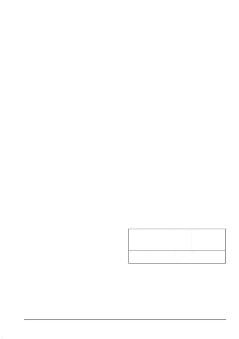
Table excerpt regarding significance of the
s
IP code
IP XY
(1
digit X)
2 ≥ 12.5 mm dia.
4 ≥ 1.0 mm dia.
st
against foreign
Protection
object entry
IP XY
(2
digit Y)
Protection
against the
nd
penetration of
water
0 not protected
4 splashing water
Electromagnetic Compatibility (EMC)
Interference emission EN 61326-1:2006
class B
Interference immunity EN 61326-1:2006
GMC-I Messtechnik GmbH 13
Page 14

8 Maintenance
Attention!
!
Attention!
!
8.1 Housing
No special maintenance is required for the
housing. Keep outside surfaces clean. Use a
slightly dampened cloth for cleaning. Avoid
the use of cleansers, abrasives or solvents.
8.2 Replacing the Fuse
Instructions on checking the zero point and
fuse are given in chapter 5.1.
Disconnect the instrument from the
measuring circuit before removing
the fuse for replacement!
Eliminate the cause of the overload after the
fuse has blown before putting the instrument
back into service!
The fuse holder is situated between the
mains power cable and the probe connector
socket. The characteristic value of the fuse is
indicated on the front plate or in chapter 7.
Please make absolutely sure that
only the specified fuse is inserted!
If fuses with other blowing characteristics, other current ratings or other
breaking capacities are used, the operator is placed in danger, and protective diodes, resistors and other
components may be damaged.
The use of mended fuses or short-circuiting
the fuse holder is prohibited.
The defective fuse can be disposed of with
the trash.
8.3 Recalibration
The respective measuring task and the
stress to which your measuring instrument is
subjected affect the ageing of the components and may result in deviations from the
guaranteed accuracy.
If high measuring accuracy is required and
the instrument is frequently used in field
applications, combined with transport stress
and great temperature fluctuations, we recommend a relatively short calibration interval
of 1 year. If your measuring instrument is
mainly used in the laboratory and indoors
without being exposed to any major climatic
or mechanical stress, a calibration interval of
2-3 years is usually sufficient.
During recalibration* in an accredited calibration laboratory (DIN EN ISO/IEC 17025) the
deviations of your instrument in relation to
traceable standards are measured and documented. The deviations determined in the
process are used for correction of the readings during subsequent application.
We are pleased to perform DAkkS or factory
calibrations for you in our calibration laboratory. Please visit our website at
www.gossenmetrawatt.com (→ Company
→ DAkkS Calibration Center or → FAQs →
Calibration questions and answers).
By having your measuring instrument calibrated regularly, you fulfill the requirements
of a quality management system per
DIN EN ISO 9001.
Standards DIN VDE 0701-0702 and
IEC 63353 (VDE 0751) stipulate that only measuring instruments which are regularly tested
and calibrated may be used for testing.
* Verification of specifications or adjustment ser-
vices are not part of the calibration. For products
from our factory, however, any necessary adjustment is frequently performed and the observance of the relevant specification is confirmed.
14 GMC-I Messtechnik GmbH
Page 15

Note:
These tests can be performed on-site with
the SECU-cal 10 calibration adapter accessory.
8.4 Return and Environmentally Sound Disposal
The test instrument is a category 9 product
(monitoring and control instrument) in accordance with ElektroG (German electrical and
electronic device law). This device is subject
to the RoHS directive. Furthermore, we
make reference to the fact that the current
status in this regard can be accessed on the
Internet at www.gossenmetrawatt.com by
entering the search term WEEE.
We identify our electrical and electronic devices in accordance with
WEEE 2012/19/EU and ElektroG
with the symbol shown to the right
per DIN EN 50419.
These devices may not be disposed of with
the trash.
Please contact our service department
regarding the return of old devices (see
chapter 10).
Description Type Article
Probe for measuring protective conductor resistance, e.g. at rotating devices under test
Calibration adapter for test instruments per
DIN VDE 0701-0702/IEC 63353 (VDE
0751) (max. 200 mA
Test adapter for electrical devices and
extension cables with CEE plug-andsocket devices
Barcode scanner, printer and RFID scanner see separate
datasheet ID systems
PC Analysis Software
For further information on software, please refer to our website
http://www.gossenmetrawatt.com
(→ Products → Electrical Testing →
pliances
→
or
http://www.gossenmetrawatt.com
(→ Products → Software → Software for Testers)
)
Testing of Electr. Ap-
MINITEST)
number
Brush
probe Z745G
SECUcal 10 Z715A
VL2 E Z745W
9 Accessories
9.1 Standard Equipment
Please refer to page 3 for the standard
equipment accessories.
9.2 Order Information for Available
Accessories
The accessories available for your measuring instrument are regularly examined for
Case / carrying pouches
Case for MINITEST Master,
MINITEST Pro
and MINITEST Base
Universal carrying pouch for
MINITEST Master,
MINITEST Pro
and MINITEST Base
Universal carrying pouch big
for MINITEST 3P Master
Case Z740B
F2000 Z700D
F2010 Z700F
compliance with the currently applicable
safety standards and are extended to include new application fields, if necessary.
The suitable, up-to-date accessories for
your measuring instrument are shown on
our website www.gossenmetrawatt.com
with the associated photo, order number,
description and, depending on the scope of
the accessories, datasheet and operating instructions.
GMC-I Messtechnik GmbH 15
Page 16

10 Repair and Replacement Parts Service
Calibration Center* and Rental Instrument
Service
If required please contact:
GMC-I Messtechnik GmbH
Service Center
Thomas-Mann-Str. 20
90471 Nürnberg · Germany
Phone: +49 911 817718-0
Fax: +49 911 817718-253
E-mail
www.gmci-service.com
This address is only valid in Germany.
Please contact our representatives or subsidiaries for service in other countries.
* DAkkS
Electrical Quantities: D-K-15080-01-01 ,
accredited per DIN EN ISO/IEC 17025:
2005
Accredited quantities: direct voltage, direct current
value, direct current resistance, alternating voltage,
alternating current value, AC active power, AC apparent
power, DC power, capacitance, frequency and
temperature
service@gossenmetrawatt.com
Calibration Laboratory for Measured
Competent Partner
GMC-I Messtechnik GmbH is certified in
accordance with DIN EN ISO 9001:2008.
Our calibration laboratory is accredited per
DIN EN ISO/IEC 17025:2005 by the
Deutscher Kalibrierdienst (German Calibration Service) under registration number
D-K-15080-01-01 .
We offer a complete range of expertise in the
field of metrology: from test reports and fac-
tory calibration certificates, right on up to
DAkkS calibration certificates.
Our spectrum of offerings is rounded out
with free test equipment management.
Our service department includes an on-site
DAkkS calibration bench. If errors are discovered during calibration, our specialized personnel are capable of completing repairs
using
original replacement parts.
As a full service calibration lab, we can calibrate instruments from other manufacturers
as well.
11 Product Support
If required please contact:
GMC-I Messtechnik GmbH
Product Support Hotline
Phone: +49 911 8602-0
Fax: +49 911 8602-709
E-mail
Edited in Germany • Subject to change without notice • A pdf version is available on the Internet
GMC-I Messtechnik GmbH
Südwestpark 15
90449 Nürnberg •
Germany
Phone +49 911 8602-111
Fax +49 911 8602-777
E-Mail info@gossenmetrawatt.com
www.gossenmetrawatt.com
support@gossenmetrawatt.com
 Loading...