

Gossen MetraWatt MID U1281, MID U1289, MID U1387, MID U1389, MID U1381 Operating Instructions Manual
Page 1
Operating Instructions
ENERGYMETER|MID
Electronic Active Energy Meters
U1281/U1289/U1381/U1387/U1389
MAIN PISTRIBUTION – PRODUCTION
Edited in Germany • Subject to change without notice • A pdf version is available on the Internet
GMC-I Messtechnik GmbH
Südwestpark 15
90449 Nürnberg • Germany
Phone +49 911 8602-111
Fax +49 911 8602-777
E-Mail info@gossenmetrawatt.com
www.gossenmetrawatt.com
3-349-618-15
3/12.18
Page 2

1 Safety Precautions – Symbols
– Check the specified nominal voltage on the serial plate
before placing the instrument into service.
– Observe the maximum voltage of the pulse output.
– Make sure the connector cables are not damaged, and
that they are voltage-free while wiring the instrument.
– If it can be assumed that safe operation is no longer pos-
sible, the instrument must be immediately removed from
service (disconnect input voltage!). Safe operation can no
longer be relied upon if the instrument demonstrates visi-
ble damage.
The device may not be placed back into operation until
troubleshooting and repair have been performed, and
calibration and dielectric strength have been tested and
approved at our factory or an authorized service center.
– Voltage conducting parts may be exposed if the cover is
opened.
If balancing, maintenance or repair of a live open instru-
ment is required, work may only be carried out by trained
personnel who are familiar with the dangers involved.
Capacitors inside the instrument may be dangerously
charged, even after it has been disconnected from all
power sources.
– After the instrument has once again been closed subse-
quent to repair or maintenance work, insulation must be
tested with high-voltage in accordance with the values
specified in the technical data.
2 GMC-I Messtechnik GmbH
Page 3
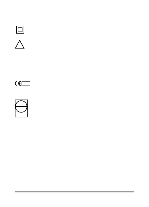
Meaning of Symbols on the Instrument
!
M111948
EB
8
11
DE MTP 11 B 001 MI-003 Prototype test certificate
Total insulation,
Safety Class II device
Warning concerning a source of danger
(Attention, observe documentation!)
This device may not be disposed of with the trash. Further information regarding the WEEE mark can be
accessed on the Internet at www.gossenmetrawatt.com
by entering the search term ’WEEE’.
Metrology label with year (M11) and registration
number of the indicated authoring for module D.
Duration of Calibration validity country specific
Label with seal from federally
approved test authority
(for recalibration only)
Tamper-proof sealing
The manufacturer‘s lead seal for calibration protection is
located at the back of the instrument.
Tamper-proof sealing for the terminal cover can be attached
either at the left or right-hand side of the terminal cover.
GMC-I Messtechnik GmbH 3
Page 4
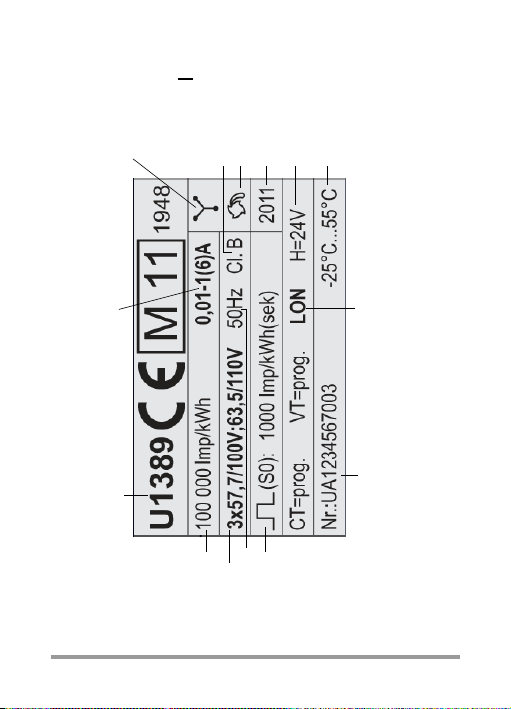
2 Serial Plate – Terminals
Type designation
U
N
f
N
LED constant
Year of manufacture
Accuracy class
CT: Current transformer transformation ratio
VT: Voltage transformer transformation ratio
Serial number
Pulse outpput
I
MIN
-I
N
(I
MAX
)
External auxiliary
Reverse Action Lock
The values of CT, VT and S on the serial plate can be / are calibrated
Operating
Bus connection
temperature range
voltage
Circuit Symbols
4-L
3-L
2-L
Y
V
U12/U1389:
U1387:
U12/U1381:
4 GMC-I Messtechnik GmbH
Page 5
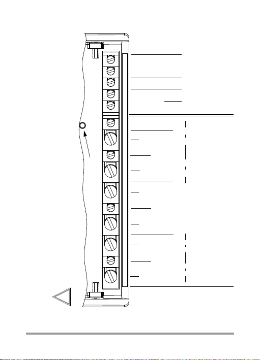
Voltage Voltage Voltage
Current Current Current
L3L2L1 N
S0
CurrentCurrentCurrent
Inputs
2.5 mm
2
with wire end ferrules or
16 mm
2
without wire end ferrule
2 x 1.5 mm
2
without wire end ferrule
Voltage:
Current:
2.5 mm
2
with wire end furrule or
2 x 1.5 mm
2
without wire end ferrule
Auxiliary voltage
H
BUS
Enable key
24 V
10%
(Feature H1)
Pulse
output
H
12 3 4 5 6 78 9112021222324
+
–
Tighten screws by hand only! Tightening torque
Note:
Observe the wiring diagram in the terminal cover
Attention:
!
for current terminals (No. 1, 3, 4, 6, 7 and 9) = 2 Nm
for all other terminals (No. 2, 5, 8, 11, 20 to 24) = 0.4 Nm
GMC-I Messtechnik GmbH 5
Page 6

3 Pulse Output – Bus Interfaces
R
L
+
20
21
U
t
External Voltage Source
Energy Import
max. 40 V
R
L
20
21
U
t
AC/DC
Energy Import
max. 375 V
~
24 V DC
I = max. 100 mA
I = max. 27 mA
U
U
External Voltage Source
Standard pulse duration: 30 ms + 5%, Interpulse period: > 30 ms
Pulse duration V7/V8: 130 ms + 5%, Interpulse period: > 130 ms
Pulse rates fix V1/V3
Direct
Transformer
CT = VT = 1 (Q0) 1000
CT, VT progr. (Q1) 1000
CTxVT; CT, VT fix (Q9)
1 10
11 100
101 1000
1001 10 000
10001 100000
1000011000 000
underligned values are default values in as-delivered condition
The interface descriptions for the active energy meters are
available on the Internet under www.gossenmetrawatt.com.
6 GMC-I Messtechnik GmbH
1000puls./kWh
f (primary) f (primary)
1000puls./kWh
100 pulses/kWh
10 pulses/kWh
1 pulses/kWh
0,1 pulses/kWh
0,01 puls./kWh
V7
V8 fix V9 Programmable V2/V4
U1281 / U1289
100 — — 1 1000
U1381 / U1387 / U1389
puls./kWh
puls./kWh
f (secondary)
100
1000
100
1000
1
1000
100
10000
1
1000
—1 1000 pulses/kWh
—0,1 100 pulses/kWh
—0,01 10 pulses/kWh
—1 1000 pulses/MWh
—0,1 100 pulses/MWh
— 0,01 10 pulses/MWh
10000puls./kWh
10000
pulses/kWh
puls./kWh
Page 7

4 Display and Control Panel
4.1 Test LED
The test LED is located between the LCD and the serial
plate. The higher the measured power value, the higher the
blink rate. If all currents are lower than the starting current,
the LED lights up permanently.
LED Constant
U128x: 10 000 pulses/kWh
U138x: 100 000 pulses/kWh
4.2 Resolution of Energy Import Main Display (Large Characters)
Meter
Feature
U1281, U1289 — — 123456.7 23456.78 kWh
Q0 or Q9 1 10 12345.67 2345.678 kWh
Q9
U138x
Q1
For calibratable main displays (Q0 or Q9), the calibration reading
*
indicates an additional digit after the decimal point. Therefore,
the leading digit is omitted in the case of 7-digit presentation.
CTxVT
CTxVT
min.
max.
11 100 123456.7 23456.78 kWh
101 1000 1234567 234567.8 kWh
1001 10000 12345.67 2345.678 MWh
10001 100000 123456.7 23456.78 MWh
100001 1000000 1234567 234567.8 MWh
1 10 123456.7 kWh
11 100 1234567 kWh
101 1000 12345.67 MWh
1001 10000 123456.7 MWh
10001 100000 1234567 MWh
Standard
Reading
Calibration
Reading *
Unit
GMC-I Messtechnik GmbH 7
Page 8

4.3 Meanings of Symbols on the LCD
Main display (active energy Etot* in kWh or MWh)
Auxiliary display (instantaneous power Pmom*)
Error: alternating error code and instantaneous power
* U138x: CT and VT are taken into consideration
U
8 GMC-I Messtechnik GmbH
Main display
if
Correct connection:
Continously lit phase symbols
Phase failure:
Symbol for affected phase is cleared from display.
Incorrect phase sequence:
Phase symbols blink in the following order: 3-2-1.
Negative power:
Respective phase symbol blinks.
4 quadrant display of instantaneous power: positive or negative active power P, positive or negative reactive power Q.
For bus connection: appears when the
meter transmits a data packet.
is not/cannot be calibrated,
U
is displayed.
Page 9

Key Symbols for Parameters Configuration
Key and 2
nd
key bit blanked:
Parameters CT, VT or S0 configurable according to features, can be disabled with enable key.
Key displayed with one key bit:
Parameters CT, VT or S0 disabled,
can be changed after activating enable key.
Key blanked, 2
nd
key bit displayed:
Parameters CT, VT or S0 (which are / can be calibrated)
are preset at the factory, can be queried in the display
mode, other values can be set.
Key with 2
nd
key bit displayed: parameters (which can be /
are calibrated) are preset at the factory, other values are
disabled with enable key and can be reset after cancelling the disable function.
Values which are preset at the factory are specified additionally on the serial plate in as-delivered condition.
Symbols Adjustable
parameters
CT, VT
S0
CT, VT
S0 CT, VT V2/V4 and Q0/Q9
Disabled
parameters
CT, VT Q1
S0 V2, V4
CT, VT S0
S0 CT, VT V2/V4 and Q0/Q9
Fixed/
calibrated
parameters
S0
S0, CT, VT V1/V3 and Q0/Q9
S0, CT, VT V7/V8/V9 and Q0
Feature
Q1
V2, V4
Q1 and V1/V3/V7/V8/V9
Q1 and V1/V3/V7/V8/V9
GMC-I Messtechnik GmbH 9
Page 10

4.4 Key Operation
Querying parameter values CT, VT and S0
Apart from the LCD test, the menu key located between
LCD and serial plate serves to query current paramter values and, in the case of active energy meters with special
features, to change parameters (provided that the enable
key has been activated before). The sequence can be seen
from the figure on the right.
If no key is pressed for 2 minutes, the display returns automatically to the standard setting.
Parameters can be changed in the following instruments:
Parameters CT, VT for U138x with feature Q1,
parameters S0 for U128x/U138x with feature V2/V4
a) Enabling parameter modifications
The enable key serves to enable or disable paramter
changes. It is located below the terminal cover and is activated with a pointed object (e. g. ballpen).
Pressing the key for the first time activates operating mode
„Change parameters“ (key off):
Renewed activation disables operating mode „Change
parameters“ (key on):
If the key is not activated for approx. 2 minutes, operating
mode „Change parameters“ is automatically aborted and
blocked.
The key is displayed again:
10 GMC-I Messtechnik GmbH
Page 11

b) Changing parameter values
➭ Briefly press the enable key first, as described under
Item a) (activates operating mode „Change parameters“).
➭ Press and hold the menu key once until the read-out
test is displayed.
➭ Repeatedly press the menu key until the parameter to
be changed appears at the display.
➭ Press and hold the menu key until the parameter value
at the digit with the highest value (on the far left-hand
side) blinks.
➭ You can increase the value of the blinking digit by
pressing the menu key (fast scroll when key is held). If
the key is not activated for a few seconds, the selected
digit is stored and the entry cursor moves one digit to
the right. The selected value is stored when the digit
with the lowest value (on the far right-hand side) stops
blinking.
➭ Press the menu key several times until the standard dis-
play appears.
➭ Press the enable key once more. This disables operat-
ing mode „Change parameter values“.
Query and Configuration of LON-Bus (Feature W1)
M-Bus (Feature W2) and L-Bus (Feature W3)
The interface descriptions for the active energy meters with
bus connection are available on the internet under
www.gossenmetrawatt.com.
GMC-I Messtechnik GmbH 11
Page 12

00013.8
10
kVArh
VAr
123456.7
1
234
kWh
kW
100
Ct
1
V
t
1000
PER
888888.8
8
888888.8
kWh
kWh
0200
Ct
0002
V
t
M
1000
PER
kWh
Auto
Auto
Auto
kWh
S0
M
M
M
m
m
001000.0
0
000010.0
kWh
kWh
m
m
Primary energy
Secondary energy
Calibration
m
Standard
Read-out test
M
Auto
0001.00
0000
V
er
Firmware version
Pulse rate
vt
ct
m m
...
M
Auto
Read-Out
S0
AutoAutoAuto Auto Auto
U138x with Feature Q1
U138x with Feature Q1
Feature V2/V4
Parameter modifications
only after enabling
bus-specific menus see
interface descriptions
0.100
seC
S0
m
Auto
Pulse duration
Setup
range
0.030 ...
3.000 s
read-out
Auto
M
Feature V2/V4
0.100
seC
S0
Setup
range
see
chapter 3
12 GMC-I Messtechnik GmbH
Page 13

Key
Auto Automatic scrolling
ct Transformation ratio current
m Press the menu key briefly
M Press and hold the menu key
Q1 Feature: Transformation ratios programmable
S0 Pulse rate S0 output
vt Transformation ratio voltage
V2/V4 Feature: rate programmable
V9 S0 rate customized
00049.90
00F0Hzz00
m m
...
m
M
Auto
Multifunctional display Feature M1 M2 M3
Reactive energy kVArh —• •
Phase voltage U1N, U2N, U3N •—•
Delta voltage U12, U23, U13 •—•
Current I1, I2, I3 •—•
Active power P1, P2, P3, Ptot •—•
Reactive power Q1, Q2, Q3, Qtot •—•
Apparent power S1, S2, S3, Stot •—•
Power factor PF1, PF2, PF3, PFtot •—•
Frequency F •—•
GMC-I Messtechnik GmbH 13
Page 14

5 Error Messages – Reset
Read-out
If an error occurs, the respective error code and instantaneous power are displayed alternately.
Error Code Meaning Cause/Remedy
E0VHi1
E0VHi 2
E0VHi 3
E01Hi1
E0 1Hi 2
E 01Hi 3
E 0SYnc
E0 EnErgY
E 0cALib
E 0AnALog
Maximum value for U1
exceeded
Maximum value for U2
exceeded
Maximum value for U3
exceeded
Maximum value for I1
exceeded
Maximum value for I2
exceeded
Maximum value for I3
exceeded
Frequency measuring
error
Meter defective
Balancing required
DC offset too high
Meter connected to
direct voltage
Send meter to repair
department
Reset
In the event of malfunction or or after eliminating an error,
the device can be reset briefly by disconnecting auxiliary
power or supply power.
6 Product Support
GMC-I Messtechnik GmbH
Product Support Hotline
Phone +49 911 8602-500
Fax +49 911 8602-340
E-Mail support@gossenmetrawatt.com
14 GMC-I Messtechnik GmbH
Page 15

7 Declaration of Conformity U128x (U138x: see reverse)
GMC-I Messtechnik GmbH 15
Page 16

8 Repair and Recalibration
Note for Test Laboratories
Directly measuring meters (U128X):
In as-delivered condition, screw terminals 2, 5 and 8 are
tightened in order to establish contact between current and
voltage inputs.
If isolated voltage supply is required for tests, the screw terminals can be released (remove screw cover, release
screws, pull insulating sleeves over contact pins in the terminals and connect simulator voltage).
Calibration Reading
For testing and calibration purposes the energy values can
be displayed with a higher resolution. Press the menu key,
as shown in the flowchart in chapter 4.4. Refer to chapter
4.2 for the type and feature dependant resolutions.
Recalibration by our federally approved test authority EB-8
is possible at any time.
GMC-I Service GmbH
Service Center
Beuthener Straße 41
90471 Nürnberg • Germany
Phone +49 911 817718-0
Fax +49 911 817718-253
E-Mail service@gossenmetrawatt.com
www.gmci-service.com
This address is only valid in Germany.
Please contact our representatives or subsidiaries for ser-
vice in other countries.
16 GMC-I Messtechnik GmbH
 Loading...