

Operating Instructions
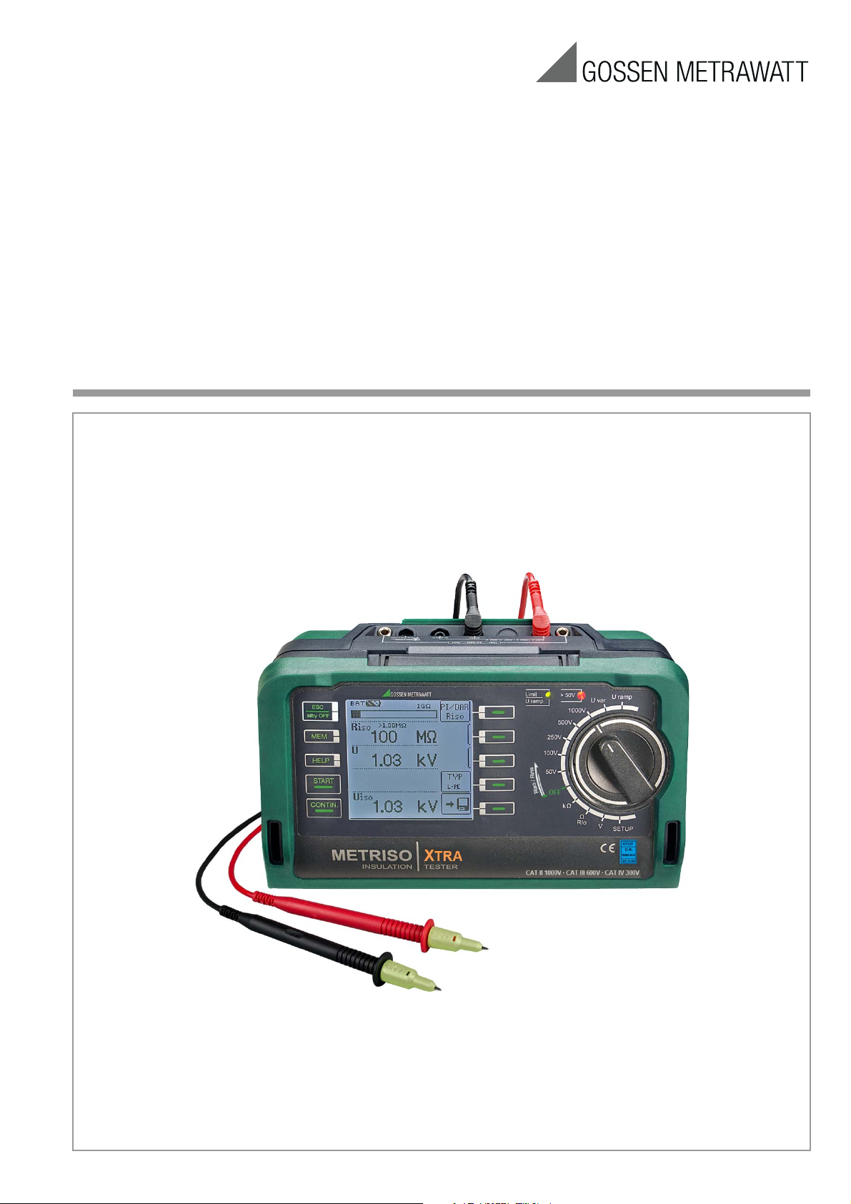
METRISO XTRA
High-Precision Insulation, Low Resistance and Voltage Measurement Instrument
3-349-818-03
2/12.17
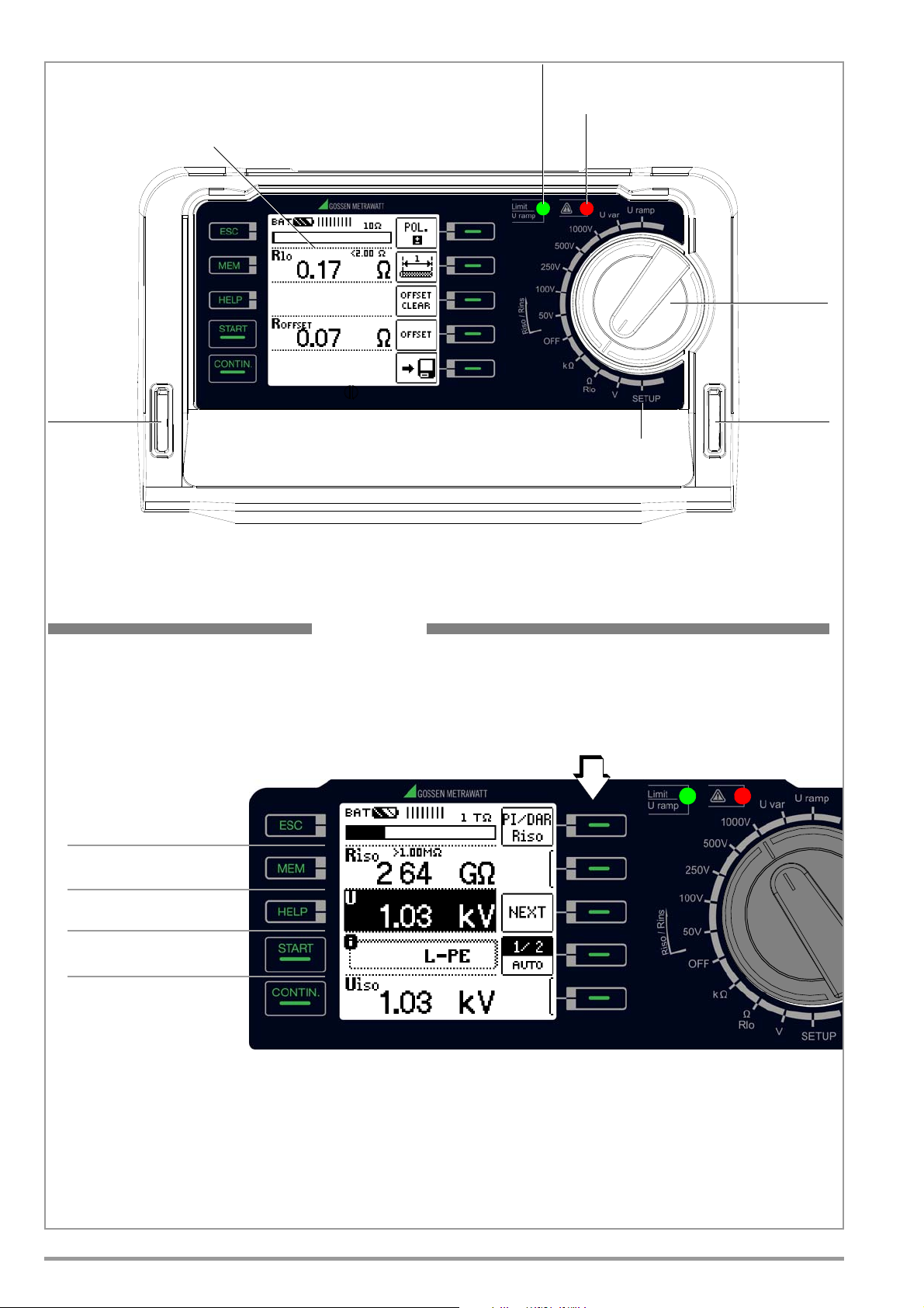
LCD Panel
Red LED: limit value exceeded
Red LED:
– Interference voltage with device off
Setup Menu
Function
Selector Switch
Slot for
Carrying Strap
Slot for
Carrying Strap
Green LED: limit value adhered to
– High test voltage at the measuring terminals
MEM: Key for memory
functions
ESC: Exit submenu /
activate instrument
standby state
Control panel
Fixed Function Keys
LEDs → section 4.3
CONTIN: Continuous
measurement of
Rins and R (kΩ)
HELP: Access context
sensitive help
START: Start measurement
Softkeys
• Parameter selection
• Limit value specification
• Entry functions
• Memory functions
METRISO XTRA
during Riso/Rins
2 GMC-I Messtechnik GmbH
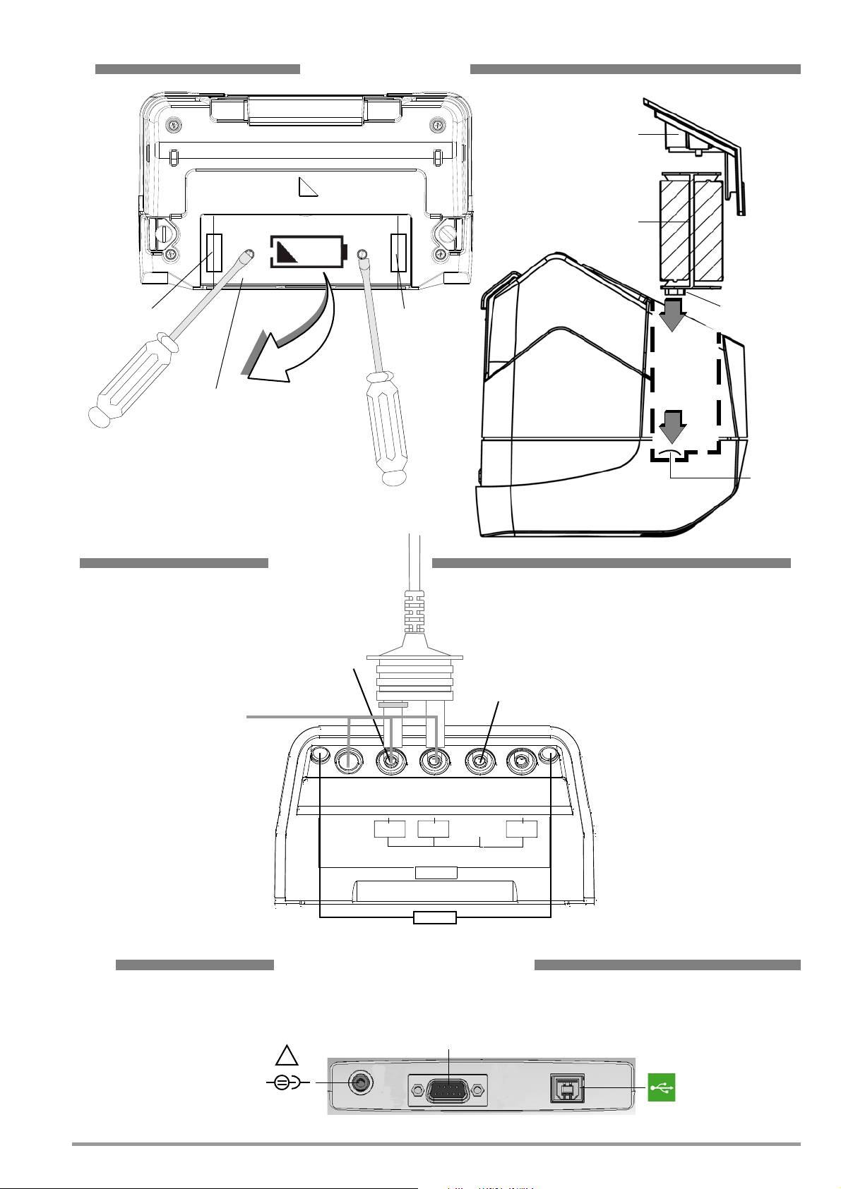
Battery Holder
Battery Compartment Lid
Battery Holder
Contacts
Battery
Contact
Spring
User Interface
Batteries, Fuses
Measuring
!
RS 232
+
COM
+
COM
SHIELD
SHIELD
Option KS-C (Z541F)
Option Z550A*
Charger Socket, Interfaces
These connections are located under a protective rubber flap.
a b
Replacement
Fuse
Socket for Z502R charger
Caution!
Make sure that no batteries are inserted
before connecting the charger.
The test instrument must remain off
during the charging process.
Fuse
Inserting the Battery Holder (side view)
USB slave for
PC connection
Port for connecting Barcode/RFID reader
GUARD
* Regarding Z550A:
Test Probe with measurement key
remote control and LED for
illuminating the measuring point:
Do not use when measuring PI and
DAR.
Compartment Lid
Battery
Compartment
Connections
Test Resistor 10 MΩ
GMC-I Messtechnik GmbH 3
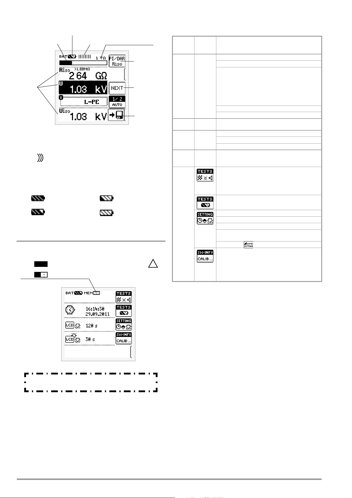
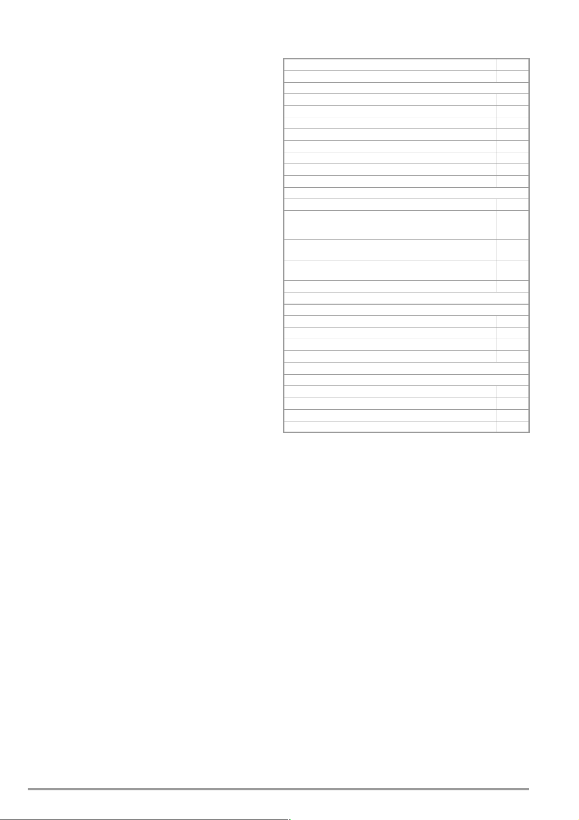
Overview of Device Settings and Measuring Functions
Battery level
Bar graph display
Measurement
Upper range limit
Measuring
Parameter
Display panel
Save
Battery full
Battery OK
Battery weak
Battery (nearly)
Battery Level Indicator
BAT
BAT
BAT
BAT
depleted U < 8.5 V
Measuring Status
Measurement in progress: Bars moves from left
Measurement on pause: Bars are static.
to right.
||||||||||
||||||||||
Polarity reversal‚
L-PE / N-PE for
documentation
setting
value
quantities
indicator
in progress
Memory Occupancy Display
MEM
Memory half full
MEM
Memory full > transfer data to PC!
These operating instructions describe a tester with
software version SW-VERSION (SW1) 01.02.00.
!
Relative to Rotary Switch Setting
Switch
setting,
see as of
RISO
RINS
page 15
kΩ
page 20
RLO
page 21
V
page 14
SETUP
Pictograph
Device settings,
measuring functions
RINS Insulation resistance
U Voltage at the test probes
U
fix Fixed test voltage,
N
Uvariable Variable test voltage, limit value:
Uramp Variable test voltage,
PI Polarization index
DAR Absorption index
R Resistance measurement
RLO Low-resistance with polarity reversal
RLO+, RLO–
R
OFFSET Offset resistance
U Voltage measurement
Tests: LCD pixel display
Battery test Ubat
limit values per VDE 0100
1 MOhm (for go/no-go display
while saving the measured value)
ramp: triggering/breakdown voltage
Low-resistance, single-pole
LCD pixel display
All pixels off
Green limit LED All pixels on
Red limit LED Acoustic signal
Date/time
CULT Language (D, GB)
Brightness
page 8
SET on: On-time for
Contrast Default settings
Device type
Serial number
Software version
Hardware version
Calibration date
Adjustment date
LCD and tester
Scope of delivery:
1 Insulation and resistance measuring instrument
1 DAkkS calibration certificate
1 Set batteries (8 pieces in battery holder)
1Carrying strap
1 Alligator clip
1 KS17-4 cable set
1USB cable
1 Condensed operating instructions
1 Supplement Safety Information
– Detailed operating instructions for download from our website
at www.gossenmetrawatt.com
4 GMC-I Messtechnik GmbH

Table of Contents Page Page
1 Applications ......................................................................6
1.1 Optional Z550A Remote Control .................................................. 6
1.2 Overview of Measuring Instrument Performance
Features ...................................................................................... 6
2 Safety Features and Precautions .....................................7
3 Initial Start-Up .................................................................. 7
3.1 Battery test ................................................................................. 7
3.2 Installing or Replacing Batteries ................................................. 7
3.3 Charging the Batteries in the Tester ........................................... 7
3.4 Device Settings – SETUP ........................................................... 8
4 General Operation ...........................................................11
4.1 Connecting the Instrument ....................................................... 11
4.2 Switching On, Monitoring and Switching Off ............................ 11
4.3 Optical Indicators ..................................................................... 11
4.4 Measurement Value Display and Memory ................................ 12
4.5 Help Function ............................................................................ 12
4.6 Setting Measuring Parameters
using Insulation Resistance Measurement as an Example ....... 12
4.7 Specifying Nominal Voltage for Uvar and Uramp ...................... 13
5 Measuring Direct Alternating Voltage ............................. 14
6 Measuring Insulation Resistance ...................................15
6.1 Measuring with Constant Test Voltage
and Nominal Value Selection via Rotary Switch Position ......... 16
6.2 Measurement with Constant Test Voltage
and Variably Adjustable Nominal Value .................................... 16
6.3 Measurement with Rising Test Voltage (ramp function)
and Variably Adjustable Final Value .......................................... 17
6.4 Insulation Resistance Measurement – Special Conditions ....... 17
6.4.1 Measurements with the Guard Cable ............................................ 17
6.5 Discharging the Device Under Test ........................................... 18
6.6 Evaluation of Measured Values ................................................. 18
6.7 Polarization Index Measurement .............................................. 18
6.7.1 Absorption Index (DAR) – DC Charging Test .................................. 19
11 Characteristic Values ...................................................... 29
12 Maintenance ...................................................................31
12.1 Firmware Revision and Calibration Information ....................... 31
12.2 Rechargeable Battery Operation and Charging ........................ 31
12.2.1 Charging Procedure with the Z502R Charger (accessory) .............. 31
12.3 Fuses ........................................................................................ 31
12.3.1 Melting Fuse ............................................................................... 31
12.3.2 Electronic Fuse ........................................................................... 31
12.4 Housing ..................................................................................... 32
12.5 Return and Environmentally Sound Disposal ............................ 32
13 Appendix .........................................................................32
13.1 Sample Connection Layouts for Insulation Resistance Measure-
ment ......................................................................................... 32
13.2 Error Messages ........................................................................ 34
13.3 Attaching the Test Probe Holder to the Carrying Strap ............. 36
13.4 Technical Data for Measurement Cables
(scope of delivery: KS17-4 safety cable set) ............................ 36
13.5 Optional Accessories (not included) ......................................... 37
14 Repair and Replacement Parts Service
Calibration Center and Rental Instrument
Service ............................................................................38
15 Recalibration ..................................................................38
16 Product Support .............................................................. 38
7 Test Resistor for Insulation Measurement for Checking the
Insulation Measuring Instrument .................................... 19
8 Measuring Resistance – kOhm Function ........................ 20
9 Measuring Low-Value Resistance of up to 10 Ohm
(protective conductor and equipotential bonding conductor) ... 21
10 Database ........................................................................24
10.1 Creating Distributor Structures, General ................................... 24
10.2 Transferring Distributor Structures ........................................... 24
10.3 Creating a Distributor Structure in the Test Instrument ........... 24
10.3.1 Creating Structures (example for electrical circuit) ......................... 25
10.3.2 Searching for Structural Elements ................................................26
10.4 Saving Data and Generating Reports ........................................ 27
10.4.1 Use of Barcode Scanners and RFID Readers ................................. 28
GMC-I Messtechnik GmbH 5
1 Applications
This instrument fulfills all requirements of applicable European and
national EC directives. We confirm this with the CE mark. The relevant declaration of conformity can be obtained from GMC-I
Messtechnik GmbH.
The METRISO XTRA insulation and resistance measuring instrument allows for quick and efficient testing of protective measures
in accordance with DIN VDE 0100, ÖVE-EN 1 (Austria), SEV 1000
(Switzerland), and regulations specific to other countries as well.
The device is equipped with a microprocessor and complies with
IEC/EN 61557 / VDE 0413 regulations:
Part 1: General requirements
Part 2: Insulation resistance
Part 4: Resistance of earth connection, protective conductors
and equipotential bonding
Part 10: Electrical safety in low-voltage systems up to 1000 V
AC and 1500 V DC – Equipment for testing, measuring
or monitoring of protective measures
As well as requirements per VDE 0701-0702:
Repair, modification and testing of electrical devices
The test instrument is especially well suited for:
•Systems setup
• Initial start-up
• Periodic testing
• Troubleshooting in electrical systems
The following measurements and tests can be performed with the
insulation measuring instrument:
• Insulation resistance
• Low-resistance
• Voltage
The following can also be tested by using a shielded measurement cable:
• Floor covering electrostatic discharge capability
1.2 Overview of Measuring Instrument Performance Features
METRISO XTRA
Article No. M550S
Measurement
U = 50, 100, 250, 500, 1000 V ✓
R
INS
Uvar = 50 ... 1000 V ✓
R
INS
Uramp (U) = 100 ... 1000 V ✓
R
INS
PI ✓
DAR ✓
R 10 ... 10 kΩ ✓
R
LO
U 0 ... 1000 V ✓
Display Functions
Backlit display ✓
Limit value LED (green/red) for:
limit values per VDE 0100
in addition to acoustic signal
URamp limit value LED for:
indicating ramp characteristics
LED for dangerous contact voltage
(when switched off)
Battery level display ✓
Special Functions
Discharge capacitive devices under test ✓
Safety shutdown (UBatt < 8 V) ✓
Data storage at the instrument ✓
ETC software for data acquisition, data management and reporting ✓
Features
Measuring categories: CAT II 1000 V / CAT II I 600 V / CAT IV 300 V ✓
Test resistance: 10 MΩ ✓
Connections: charging socket, USB port (slave), RS 232 port ✓
DAkkS calibration certificate ✓
0.01 ... 10 Ω ✓
R
INS RLO
R
INS
✓
1.1 Optional Z550A Remote Control
The optional remote control with triggering key on the test probe
and a key for illuminating the measuring point makes it possible to
use the measuring instrument at difficult to access places.
For safety reasons, a predefined voltage is only applied to the test
probes for as long as the triggering key is held depressed.
The start key on the test instrument should be used instead of
remote control for triggering polarization and absorption index
measurements, because these two measurements involve complete measuring cycles.
6 GMC-I Messtechnik GmbH
2 Safety Features and Precautions
Attention!
!
Attention!
!
Attention!
!
Attention!
!
!
XY123
2012-06
D-K
15080-01-01
Consecutive number
Registration number
Date of calibration (year – month)
Deutsche Akkreditierungsstelle GmbH – calibration lab
The electronic measuring and test instrument is manufactured
and tested in accordance with safety regulations IEC/EN 610101/VDE 0411-1 and EN 61 557.
safety of the operator, as well as that of the instrument, is assured.
Read the operating instructions thoroughly and carefully before
using your instrument. Follow all instructions contained therein.
The measuring and test instrument may not be placed into service:
• If the battery compartment lid has been removed
• If external damage is apparent
• If connector cable or measuring adapters are damaged
•If the instrument no longer functions flawlessly
• After extraordinary damage due to transport
• After a long period of storage under unfavorable conditions
(e.g. humidity, dust or extreme temperature).
Opening of Equipment / Repair
The equipment may be opened only by authorized service personnel to ensure the safe and correct operation of the equipment
and to keep the warranty valid.
Even original spare parts may be installed only by authorized service personnel.
In case the equipment was opened by unauthorized personnel,
no warranty regarding personal safety, measurement accuracy,
conformity with applicable safety measures or any consequential
damage is granted by the manufacturer.
Data Backup
We advise you to regularly transfer your stored data to a PC in
order to prevent potential loss of data in the test instrument.
We assume no responsibility for any data loss.
We recommend ETC software (Electric Testing Center) for back-
ing up, processing and managing data.
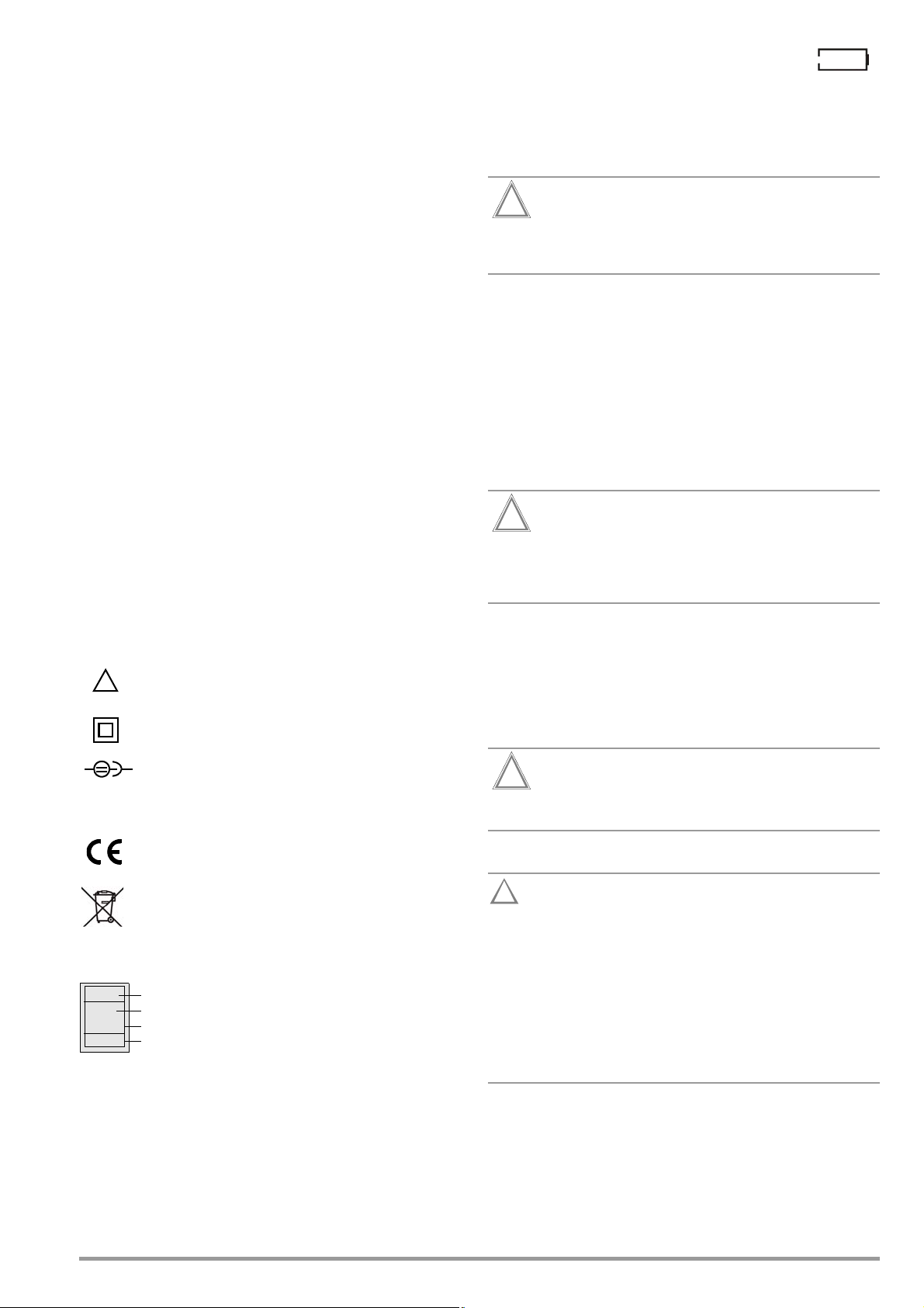
Meaning of Symbols on the Instrument
Warning concerning a point of danger
(Attention, observe documentation!)
Protection class II device
When used for its intended purpose,
If battery voltage has fallen below the allowable lower
limit, the pictograph shown at the right appears. The
instrument does not function if the batteries have been depleted
excessively, and no display appears.
3.2 Installing or Replacing Batteries
New batteries must be inserted for initial start-up, or if only one
filled segment remains in the battery symbol.
Before opening the battery compartment (see page 5 for
location), disconnect the instrument from the measuring
circuit (mains) at all poles.
Eight 1.5 V size AA batteries in accordance with IEC LR 6 are
required for operation of the insulation measuring instrument. Use
new alkaline manganese batteries only.
Rechargeable NiCd or NiMH batteries may also be used. These
can be charged externally or by connecting the Z502R charger to
the test instrument. We recommend rechargeable NiMH batteries.
Always replace batteries in complete sets.
Dispose of batteries in an environmentally sound fashion.
➭ Loosen both slotted screws for the battery compartment lid
on the back, and remove the lid.
➭ Remove the battery holder and insert eight 1.5 V size AA bat-
teries with correct polarity in accordance with the symbols.
Make sure that all of the batteries are inserted with correct
polarity. If just one battery is inserted with reversed polarity, it will not be recognized by the instrument and may
result in leakage from the batteries.
➭ Push the battery holder into the battery compartment such
that the battery holder’s contacts touch the contact springs at
the bottom of the battery compartment (see drawing on
page 3).
If the battery holder is not inserted as specified, the instrument
cannot be supplied with power.
➭ Replace the battery compartment lid and retighten the
screws.
Charging socket for extra-low direct voltage (Z502R
charger)
Attention!
Only rechargeable batteries may be inserted when the charger is connected.
EC mark of conformity
The device and included batteries may not be disposed of with the trash. Further information regarding
the WEEE mark can be accessed on the Internet at
www.gossenmetrawatt.com by entering the search
term “WEEE”.
Calibration Seal (blue seal):
See also “Recalibration” on page 38.
3 Initial Start-Up
3.1 Battery test
Four different battery symbols, ranging from fully depleted to fully
charged, continuously indicate the momentary charge level in the
upper left-hand corner of the display
GMC-I Messtechnik GmbH 7
The instrument may only be placed into service if the
battery compartment lid is securely fastened!
3.3 Charging the Batteries in the Tester
Use only the Z502R charger (available as an accessory)
to charge batteries which have already been inserted into
the test instrument.
Make sure that the following conditions have been fulfilled before connecting the charger to the charging socket:
– Rechargeable batteries have been installed with
correct
polarity (not standard batteries)
– The test instrument has been disconnected from the
measuring circuit at all poles
– The instrument must remain off during charging.
Refer to section 12.2.1 with regard to charging batteries which
have been inserted into the tester.
If the batteries or the battery pack have not been used or
recharged for a lengthy period of time (> 1 month), thus resulting
in excessive depletion:
Observe the charging sequence (indicated by the LED at the
charger) and initiate a second charging sequence if necessary
(disconnect the charger from the mains and from the test instrument to this end, and then reconnect it).
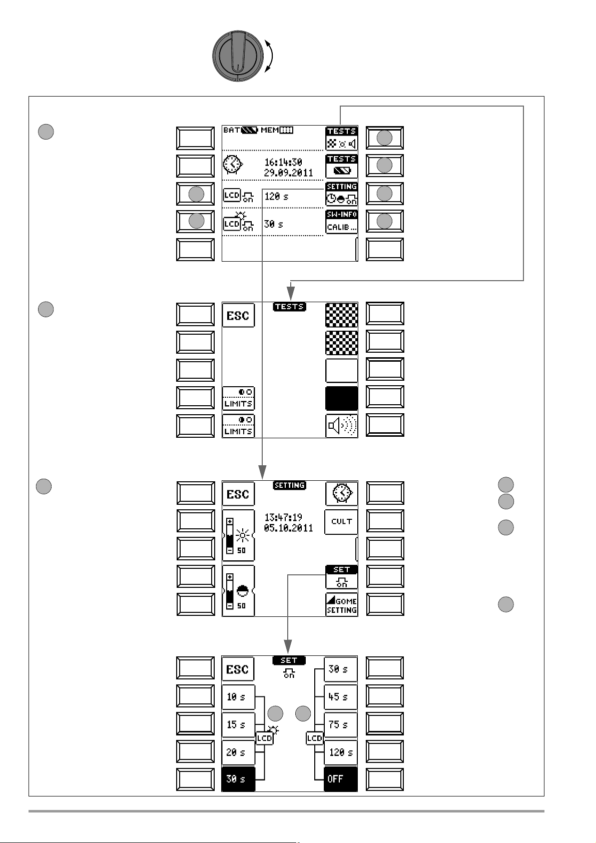
3.4 Device Settings – SETUP
SETUP
LED and LCD test menu
Battery test menu
Brightness/contrast menu
Software revision level
Calibration date
Display: date / time
Display: automatic shutdown
Display: automatic shutdown
of display illumination after 30 s.
of the tester after 120 s. Time, language, profiles
1
2
3
4
0b
0a
0
Return to main menu
Limit LED: test red
Limit LED: test green
Cell test
Inverse cell test
Hide all pixels
Show all pixels
Acoustic signal test
1
Return to main menu
Increase brightness
Decrease brightness
Increase contrast
Decrease contrast
Set time
→
Default settings →
User interface
language
→
3
3a
3b
3c
3d
Set date →
On-time for
display illumination / tester
0b
Return to submenu
0a
Display Illumination On-time
Brightness and Contrast Settings Time, On-Time and Default Settings
Menu Selections for Operating Parameters
LED Tests LCD and Acoustic Signal Tests
Test Instrument On-Time
Automatic shutdown,
deactivated = OFF
8 GMC-I Messtechnik GmbH
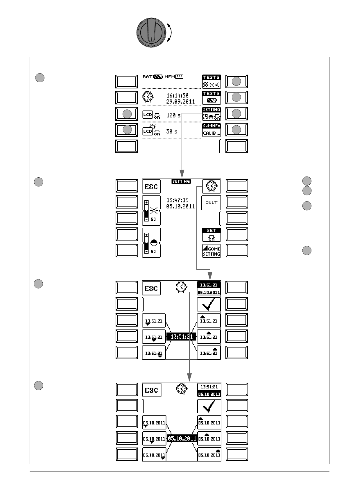
SETUP
LED and LCD test menu
Battery test menu
Brightness/contrast menu
Software revision level
Calibration date
Display: date / time
Display: automatic shutdown
Display: automatic shutdown
of display illumination after 15 s.
of the tester after 45 s.
Time, language, profiles
1
2
3
4
0b
0a
0
Return to main menu
Increase brightness
Decrease brightness
Increase contrast
Decrease contrast
Set time
→
Default settings →
User interface
language
→
3
3a
3b
3c
3d
Set date →
On-time
for display illumination / tester
Set time
Menu Selection for Operating Parameters
Adjusting Brightness and Contrast Set Time, Language, Profiles, Acoustic Signal
Set date
Select time/date
Increase
Increase
hours
Activate
settings
minutes
3a
Increase
seconds
Return to submenu
Decrease
Decrease
hours
minutes
Decrease
seconds
Select time/date
Increase
Increase
day
Activate
settings
month
3b
Increase
year
Return to submenu
Decrease
Decrease
day
month
Decrease
year
GMC-I Messtechnik GmbH 9
Significance of Individual Parameters
Note
Attention!
!
0a
0b23c
3d
4
Test Instrument On-Time
The period of time after which the test instrument is automatically
shut off can be selected here. This selection has a considerable
influence on the service life and the charging status of the batteries.
On-Time for LCD Illumination
The period of time after which LCD illumination is automatically
shut off can be selected here. This selection has a considerable
influence on the service life and the charging status of the batteries.
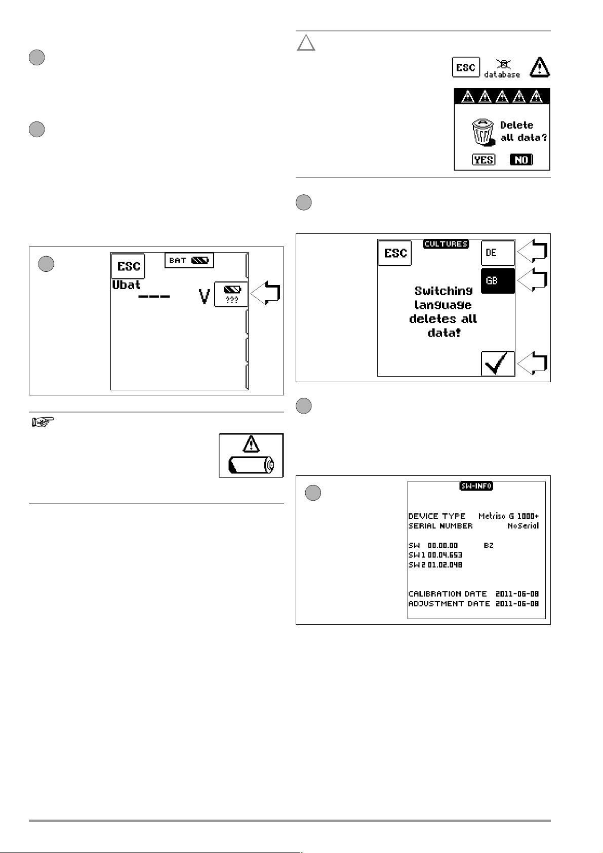
Submenu: Battery Level Query
Battery voltage U
the battery to a load.
(Uo) can be queried here without subjecting
BAT
Data are lost when the language
is changed, or if the instrument is
reset to its default settings!
Back up your measurement
data to a PC with the help of
ETC software before pressing the respective key.
The prompt window shown at
the right asks you to confirm
deletion.
User Interface Language (CULTURE)
➭ Select the desired language with the appropriate country
code and acknowledge your selection by pressing the ✓ key.
Measuring Sequence
If battery voltage drops to below 8.0 V
during the course of a measuring
sequence, this is only indicated by
means of a pop-up window. Measured
values are invalid. Measurement results cannot be saved
to memory.
➭ Press ESC in order to return to the main menu.
Default Settings (GOME SETTING)
The test instrument is returned to its original default settings when
this key is activated.
Firmware Revision and Calibration Information (example)
➭ Press any key in order to return to the main menu.
10 GMC-I Messtechnik GmbH
START/STOP SHIELD COM
Option Z550A
+
KS-C
(Z541F)
+
C
O
M
SH
I
E
L
D
Limit
Green
Limit
Red
Uramp
Green
Uramp
Red
Red
!
Limit
4 General Operation
4.1 Connecting the Instrument
The test leads are connected to the “+” and “COM” jacks.
Special Case:
When inserting
the 3-pole plug,
make sure that
the jack plug is
inserted in the
START/STOP
position. Press
and align the 3pole plug such
Test Probe for Remote Triggering (Option Z550A)
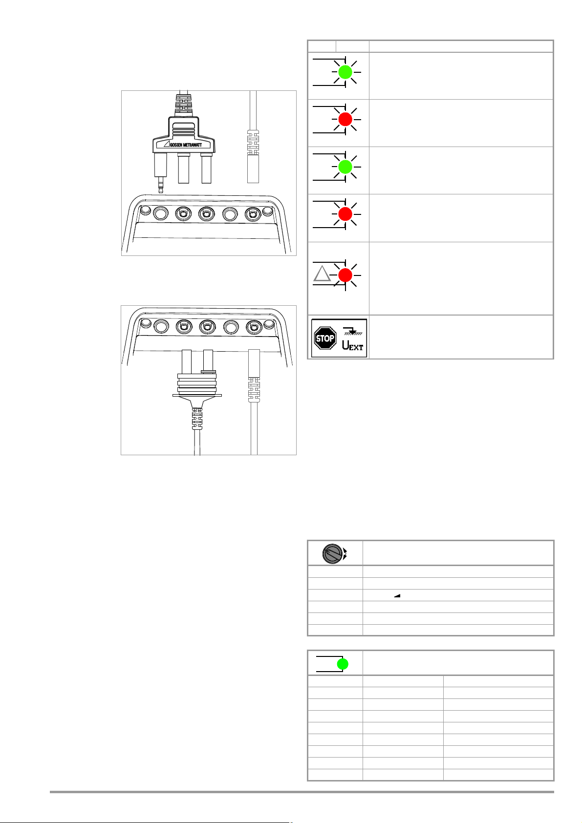
4.3 Optical Indicators
LED Status
Function – Cause
Limit Value Indication
– Measured insulation resistance does not violate the limit
value.
– Measured low-resistance Rlo does not violate the limit
value.
Limit Value Indication
– Measured insulation resistance has fallen short of the
selected limit value.
– Measured low-resistance Rlo does has exceeded the
permissible limit value.
Indication of ramp characteristics
– Maximum ramp voltage (upper voltage limit) has been
reached (without breakdown).
that it is placed
flush on the connection terminal.
This is the only
way to assure
that the three
contacts of the
jack plug are
properly connected with the command cables.
Special Case: Measuring High-Value Resistance with the KS-C Probe (Option)
When measuring
electrostatic discharge capacity
for floor coverings, the shielded
cable should be
connected to the
COM and SHIELD
jacks (KS-C
accessory set,
“cable set consisting of measurement cable
and high-resistance measurement cable for
measurements in the GΩ range”, see diagram). Be sure to
observe color coding.
1
Function testing should be executed at regular intervals (see following
section regarding testing the LEDs).
Testing the LED which Indicates Detection of Interference Voltage
when Switched Off – OFF Switch Position
➭ Apply a voltage of greater than 50 V (+ and COM jacks).
➭ Turn the rotary switch to the V position.
➭ Read the voltage value at the LCD.
➭ Turn the rotary switch to the OFF position.
Test results: If applied voltage is unchanged and the LED which
indicates the detection of interference voltage lights up red, the
Indication of ramp characteristics
– Maximum ramp voltage (upper voltage limit) has not been
reached (due to breakdown).
Breakdown voltage is displayed.
Interference voltage in switched-off condition
lings of test voltage during insulation measurement
Dangerous voltage of greater than 50 V is present at the measurement inputs:
– Initialization of insulation resistance and
low-resistance measurement is disabled.
– High test voltage is applied to the measuring terminals
(Riso/Rins, PI and DAR) during insulation measurement
Detection of interference voltage in the on-state
in the resistance measuring ranges after starting measurement
The value of interference voltage is displayed in addition to signalling
in the resistance measuring ranges for as long as it is present.
1
and signal-
LED is OK. In this case, the LED reliably indicates interference
voltage even when the instrument is switched off. We recom-
4.2 Switching On, Monitoring and Switching Off
If supply voltage drops to a value of less than 8.5 V, the
LOW BATT pop-up message appears: No more measurements
can be started.
If battery voltage falls below the allowable limit value of 8.0 V, the
mend executing this test at regular intervals.
METRISO XTRA Measuring Functions, Measuring Ranges and
Limit Values
Measuring Ranges
instrument cannot be switched on, or it is switched off.
Measurements cannot be started in the resistance measuring
ranges in the event of interference voltage.
The instrument only switches itself off automatically after comple-
tion of an (automatic) measuring sequence, and after the predetermined on-time has expired (see page 8). On-time is reset to its
original value as defined in the setup menu, as soon as any key or
the rotary function switch is activated.
/ R
R
ISO
INS
/ R
R
ISO
INS
/ R
R
ISO
INS
R 10 ... 10 kΩ
R
LO
U 0 ... 1000 V
U = 50, 100, 250, 500, 1000 V
Uvar = 50 ... 1000 V
Uramp (U ) = 100 ... 1000 V
0.01 ... 10 Ω
If the instrument is switched off automatically with the rotary
switch in any position other than OFF, it can be reactivated by
pressing the ESC key. The instrument is also reactivated if the
Limit Values
rotary switch is activated and turned through the OFF position.
/ R
Limit R
The instrument can be switched off manually by turning the rotary
switch to the OFF position.
GMC-I Messtechnik GmbH 11
ISO
PI limit Adjustable 1.0, 1.1, 1.5, 2.0, 3.0, 4.0
DAR limit Adjustable 1.25, 1.6
Limit R
LO
Fixed setting 50 kΩ @ U
INS
Fixed setting 100 kΩ @ U
Fixed setting 500 kΩ @ U
Fixed setting 1 MΩ @ U
Fixed setting 1 MΩ @ U
Fixed setting 1 MΩ @ U
Fixed setting 2 Ω
ISO/UINS
ISO/UINS
ISO/UINS
ISO/UINS
ISO/UINS
ISO/UINS
= 50 V
= 100 V
= 250 V
= 500 V
= 1000 V
= Uvar
4.4 Measurement Value Display and Memory
Note
HELP
1
2
3
2
The following appear at the display panel:
• Measurement values with abbreviations and units of measure
• Selected function
• Error messages
Measurement values for automatic measuring sequences are
stored and displayed as digital values until the next measurement
sequence is started, or until automatic shut-off occurs.
4.5 Help Function
A wiring diagram can be displayed for selected switch positions,
as well as basic functions after they have been selected with the
rotary selector switch:
➭ Press the HELP key in order to query online help.
➭ Press the ESC key in order to exit online help.
If the upper range limit is exceeded, the upper limit value is displayed and is preceded by the “>” symbol (greater than), which
indicates measurement value overrun.
The depiction of LEDs in these operating instructions
may vary from the LEDs on the actual instrument due to
product improvements.
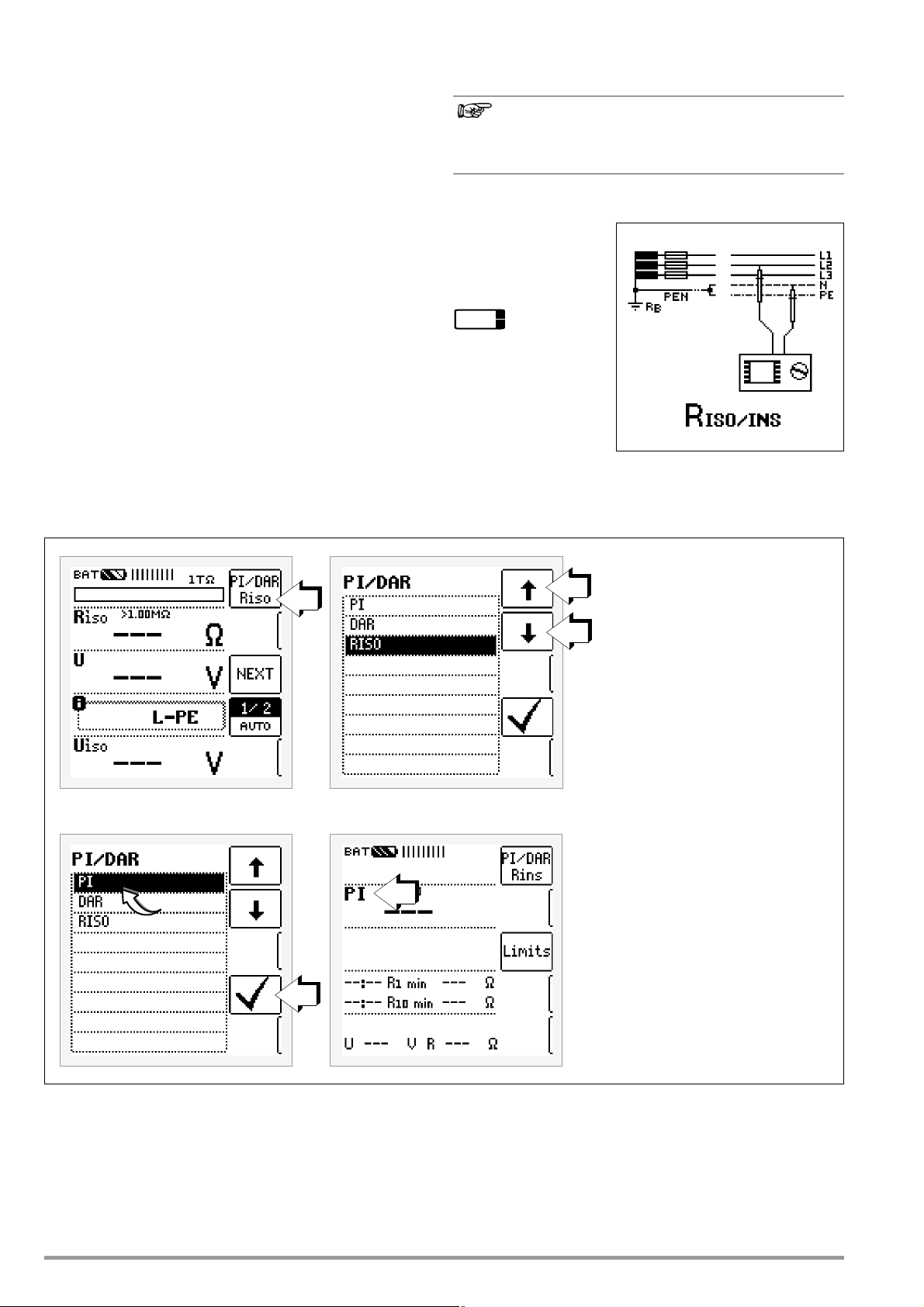
4.6 Setting Measuring Parameters using Insulation Resistance Measurement as an Example
1 Access the submenu for setting the desired parameter.
2 Select a parameter using the ↑ or ↓ scroll key.
3 The setting value is not permanently accepted for the respective measure-
ment until the ✓ key is pressed, after which the display is returned to the
main menu. You can return to the main menu by pressing ESC instead of
✓, without accepting the newly selected value.
12 GMC-I Messtechnik GmbH

4.7 Specifying Nominal Voltage for Uvar and Uramp
Note
Select value.
Select value.
↵ Accept value.
Delete characters =
✓Save value (to list).
Select the EDIT menu.
change cursor position.
Nominal voltage can be freely selected within specified limits for
the Uvar and Uramp measuring functions:
1 Access submenu for selecting the desired voltage:
Press the key with the icon.
2 Select the desired value with the left or right scroll key. The value is
accepted by pressing the ↵ key. The entire value is acknowledged by
selecting ✓ and then pressing the ↵ key.
The new nominal voltage appears at the main display.
Observe the predefined limits for the new setting value.
New, freely selected limit values or nominal values
included in the parameters list can be deleted/edited at
the PC with the help of ETC software.
GMC-I Messtechnik GmbH 13

5 Measuring Direct Alternating Voltage
Note
V
L1
L2
N
PE
L3
R
B
R
E
Max.
1.2 kV
U
+
COM
+
COMSHIELD
1
2
2
3
Direct voltage
Alternating voltage
Pulsating voltage
(DC + AC TRMS)
You can measure direct voltage, as well as sinusoidal alternating
voltage with frequencies ranging from 45 to 65 Hz, with this test
instrument.
Select Measuring Function
➭ Select the V measuring function with the rotary switch.
Connection
➭ Connect the measurement cables to the + and COM jacks.
➭ Contact the measuring point with both test probes.
Measurement
The measured value is displayed directly (without pressing the
START key) – in analog format at the bar graph and in digital format
at the matrix display.
➭ After completing the measurement, switch the instrument off
by turning the rotary switch to the OFF position.
The ESC, START and CONTIN. keys have no function in this case.
Set the waveform parameter (voltage type).
Input impedance for the voltage measuring range is
10 MΩ.
14 GMC-I Messtechnik GmbH

6 Measuring Insulation Resistance
Note
Note
R
INS
U
var
U
ramp
HELP
1/2
2/2
L-PE
N-PE
1/4
2/4
3/4
4/4
L1-PE
L2-PE
L3-PE
N-PE
AUTO1 AUTO3
R
ISO/RINS
→ MEMORY
MEMORY → R
ISO/RINS
Switch
and save
Switch
without saving
NEXT
Select Measuring Function
➭ Select the R
depending on the measuring task, constant or variable test
voltage (Uvar), or a ramp function (Uramp).
Connection
measuring function with the rotary switch and,
INS
Semiautomatic Measurement in Multipole Systems
Fast, semiautomatic polarity reversal is possible in all rotary switch
positions for insulation resistance measurement. However, polarity selection is only relevant for documentation.
Fast Polarity Reversal
The polarity parameter is set to AUTO1 (single-phase mains voltage) or AUTO3 (3-phase mains voltage).
There are two ways to quickly and conveniently switch amongst
all polarity variants without switching to the parameter settings
submenu:
• Press the NEXT key.
• Press the save key at the instrument twice after each measurement.
➭ Connect the device under test to the + and COM jacks.
Sample connection layouts for insulation resistance measurement
are included in section 13.1.
Insulation resistance can only be measured at voltage-free
objects. If mains voltage or interference voltage is applied to the
measurement inputs, measurement cannot be started.
Checking Measurement Cables Before Measurements
Before performing insulation measurement, the test
probes on the measurement cables should be short-circuited in order to assure that the instrument displays a
value of less than 1 kΩ (see section 9). In this way, incorrect connection can be avoided and broken measurement cables can be detected.
Continuous Measurement via the CONTIN. Key
The instrument’s batteries are rapidly depleted during the
insulation resistance measurement. Stop continuous
measurement with “constant test voltage” as soon as the
display has settled in.
GMC-I Messtechnik GmbH 15

6.1 Measuring with Constant Test Voltage and Nominal Value
Note
Polarization index
Test voltage switch position:
50 V / 100 V / 250 V / 500 V / 1000 V
Absorption index
Insulation resistance
START
CONTIN
Variable test voltage
50 V ... 1000 V
(constant nominal value):
START
CONTIN
Selection via Rotary Switch Position
Set Parameters
6.2 Measurement with Constant Test Voltage and Variably Adjustable Nominal Value
A test voltage which deviates from nominal voltage, and is usually
lower, can be selected for measurements at sensitive components, as well as systems with voltage limiting devices.
Set Parameters
The constant test voltage function offers two options:
• After briefly pressing the START key, specified test voltage UN is
read out and insulation resistance RINS is measured. As soon
as the measured value is stable (settling time may be several
seconds in the case of high cable capacitance values), measurement is ended and the last measured values for RINS and
UINS are displayed. U is the voltage which is measured at the
test probes during and after testing. This voltage drops to a
value of less than 10 V (see section entitled “Discharging the
Device Under Test”.
or
• As soon as you press the CONTIN key, test voltage UN is applied
and insulation resistance RINS is measured. Do not press the
key again in order to stop measurement until the measured
value has settled in (settling time may be several seconds in
the case of high cable capacitance values). Voltage U, which
is measured during testing, corresponds to voltage UINS.
After once again pressing the CONTIN key, measurement is
ended and the last measured values for RINS and UINS are
displayed. U drops to a value of less than 10 V after measurement (see the section entitled “Discharging the Device Under
Test”.
Start Measurement
Refer to section 4.7 regarding how to enter the variable voltage.
The selected nominal voltage is displayed in the main menu.
❏ Pole Selection Report Entry
The poles between which testing takes place can only be entered
here for reporting purposes. The entry itself has no influence on
the actual polarity of the test probes or pole selection.
Start Measurement
After pressing the START key, nominal voltage UN (50 to 1000 V)
entered previously via the parameters menu is applied until the
measured values settles in.
After pressing the CONTIN. key, the previously selected test voltage
or nominal voltage U
key is pressed once again.
(50 to 1000 V) is applied until the CONTIN.
N
U is the voltage which is measured at the test probes during and
after testing. This voltage drops to a value of less than 10 V after
measurement (see section 6.5, “Discharging the Device Under
Test’ ’) .
Test voltage U
After pressing the START key, nominal voltage UN (50 ... 1000 V)
selected with the rotary switch is applied until the measured values settles in.
After pressing the CONTIN. key, the previously selected test voltage
or nominal voltage U
key is pressed once again.
U is the voltage which is measured at the test probes during and
after testing. This voltage drops to a value of less than 10 V after
measurement (see section 6.5, “Discharging the Device Under
Test’’).
Test voltage U
16 GMC-I Messtechnik GmbH
(50 to 1000 V) is applied until the CONTIN.
N
is displayed for U
INS
.
is displayed for U
The instrument’s batteries are rapidly depleted during the
insulation resistance measurement. Stop continuous
measurement with “constant test voltage” as soon as the
display has settled in.
INS
.

6.3 Measurement with Rising Test Voltage (ramp function)
Note
Attention!
!
Attention!
!
Note
Maximum test voltage
100 V ... 1000 V
(final ramp value)
Max. 1 mA (at 1 KΩ/V)
Current load:
START
+Measurement Cable
–Measurement Cable
Guard Cable
Conductor
Insulation
Material
Guard Rings
Contact Ring
(COM)
and Variably Adjustable Final Value
The “Uramp” rising test voltage function (ramp function) is used to
detect weak points in the insulation, as well as to determine
response voltage for voltage limiting components.
Set Parameters
6.4 Insulation Resistance Measurement – Special Conditions
Insulation resistance can only be measured at voltagefree objects.
If measured insulation resistance is less than the selected limit
value, the limit LED lights up red.
Refer to section 4.7 regarding how to set the final ramp value. The
selected nominal voltage value is displayed in the main menu.
❏ Pole Selection Report Entry
The poles between which testing takes place can only be entered
here for reporting purposes. The entry itself has no influence on
the actual polarity of the test probes or pole selection.
Start Measurement
After briefly pressing the START key, test voltage is continuously
increased until the specified nominal voltage U
reached.
Insulation measurement with rising test voltage is ended:
• As soon as specified maximum test voltage U
the measured value is stable
or
• After sparkover occurs at breakdown voltage
(100 ... 1000 V) is
N
is reached and
N
If an interference voltage of roughly
– Interference Voltage” appears in a pop-up window, insulation
resistance is not measured. In the case of interference voltage >
50 V, the “> 50 V” LED lights up.
In 3-phase systems, all conductors (L1, L2, L3 and N) must be
tested against PE!
Do not touch the instrument’s terminal contacts during
insulation resistance measurements!
If nothing has been connected to the terminal contacts, or if a
resistive load component has been connected for measurement,
your body would be exposed to a current of approximately 1 mA
at a voltage of 1000 V. The noticeable shock may lead to injury
(e.g. resulting from a startled reaction etc.).
≥ 15 V is present and “U
EXT
6.4.1 Measurements with the Guard Cable
The measurement of very high resistances necessitates extremely
minimal measuring current and may be rendered problematic as a
result of influences such as electromagnetic fields, humidity or
surface pollution. An accurate test set-up is thus absolutely
essential.
A guard cable must be used for measurements within a range of
100 GΩ (10 GΩ) … 1TΩ, in order to prevent surface current from
distorting measurement results. The guard rings prevent current
at the surface of the insulation material from flowing from the
+measurement cable to the –measurement cable, instead of
through the insulation material itself.
➭ Insert the plug from the guard cable into the appropriate jack
in the test instrument.
➭ Plug the alligator clip onto the guard cable test probe.
➭ Connect the alligator clip to the guard ring between the two
measuring points at the insulation material under test.
➭ Refer to section 6.1 to section 6.3 regarding the measuring
sequence.
As soon as the final ramp value is reached, the Uramp LED lights
up green. If the final ramp value is not reached due to sparkover,
the Uramp LED lights up red.
U is the voltage which is measured at the test probes during and
after testing. This voltage drops to a value of less than 10 V after
measurement (see section 6.5, “Discharging the Device Under
Test’’).
Highest achieved test voltage U or any triggering or breakdown volt-
age which occurs is displayed for U
GMC-I Messtechnik GmbH 17
.
INS
Measurement can be stopped at any time by pressing
the START key or the CONTIN. key.
The following materials can be used as guard rings: aluminum foil, copper foil or metallic hose clamps.

6.5 Discharging the Device Under Test
Attention!
!
Attention!
!
Note
PI
R
10min
R
1min
--------------=
Polarization Index
Test voltage switch position:
50 V / 100 V / 250 V / 500 V / 1000 V
Absorption index
Insulation resistance
START
If measurement is performed at a capacitive object such
as a long cable, it becomes charged with up to approx.
1000 V!
Touching such objects is life endangering!
When an insulation resistance measurement has been performed
on a capacitive object it is automatically discharged by the instrument after measurement has been completed. Contact with the
device under test must be maintained to this end. The falling voltage value can be observed at the U display.
Do not disconnect the DUT until less than 10 V is displayed for U!
6.6 Evaluation of Measured Values
Instrument measuring error must be taken into consideration in
order to assure that the limit values set forth in DIN VDE regulations are not fallen short of. The required minimum display values
for insulation resistance can be determined with the help of the
table, “
Display Values in Consideration of Measuring Uncertainty
page 30. These values take maximum device error into consideration (under nominal conditions of use). Intermediate values can
be interpolated.
”, o n
Z550A Option
Use of the measurement cable with remote start/stop is
not advisable for polarization index measurement PI or
absorption index measurement DAR, because measurement is only conducted as long as the START key is
pressed and held.
sequence is nevertheless executed, start each measurement
with the
Set Parameters
In order to assure that the entire measuring
START
key at the test instrument only.
6.7 Polarization Index Measurement
In the case of electrical machines which include components with
windings (generator and motor windings), it’s advisable to conduct polarization index testing. This procedure involves expanded
testing of insulation resistance. The accumulation of moisture and
contamination on windings can be detected as reduced insulation
resistance.
DC measuring voltage from the METRISO XTRA is applied to the
insulation for a duration of 10 minutes to this end. Measured values are documented after one minute, and after ten minutes. If
the insulation is good, the value measured after ten minutes is
higher than the value measured after one minute. The relationship
between the two measurement values is the polarization index.
The molecules within the insulation are aligned due to the application of measuring voltage over a long period of time, resulting in
polarization. The polarization index indicates whether or not the
molecules contained in the insulation can still be moved, thus
allowing for polarization. This, in turn, is an indication of the condition of the insulation. The more freely the charge carriers can be
moved, the better is the condition of the insulation.
The following rules apply in general:
PI value < 1: Troubleshooting is required.
PI value = 1 to 2: Maintenance is advisable.
PI value = 2 to 3: DUT is OK!
PI values > 3: Error-free device under test
No immediate action is required.
Preventive maintenance can be planned
according to workload.
Start Measurement
Applications
Determination of moisture and contamination levels
The selected polarization index menu is only
displayed until the rotary
For PI measurement, test instrument on-time should be
set to OFF (see section 3.4, “Device Settings – SETUP’’).
18 GMC-I Messtechnik GmbH
switch is activated or the
parameter is changed.

6.7.1 Absorption Index (DAR) – DC Charging Test
DAR
R
60s
R
30s
---------=
Polarization Index
Test voltage switch position: 50 V / 100 V / 250 V / 500 V / 1000 V
Absorption index
Insulation resistance
START
+
COM
10M
Ω
+
COMSHIELD
R
ISO/RINS
10 MΩ
The absorption index test is part of the polarization index test.
Insulation resistance measurements are placed in relationship to
one another after 30 and 60 seconds.
Applications:
Set Parameters
Faster version of the polarization index test.
The selected polarization index menu is only displayed until the
rotary switch is activated or the parameter is changed.
7 Test Resistor for Insulation Measurement for
Checking the Insulation Measuring Instrument
According to section 5.3.1.2 of VDE 0105-100 (EN 50110-1), the
following applies: “These measuring instruments must be tested
before, and if applicable after use.”
The two outermost jacks on the connection panel must be connected to each other internally via a 10 MΩ test resistor to this
end.
The sum of test resistor and cable resistance (for both cables),
including test probes, amounts to 10 MΩ ±5%. This value allows
for quick self-testing.
Start Measurement
➭ Connect the measurement cables to the + and COM jacks.
➭ Insert the test probes into the above described jacks.
➭ Select the RiSO/iNS measuring function with the rotary
switch, as well as the desired test voltage, e.g. RiSO 100V.
➭ Press the start key and view the measurement results.
GMC-I Messtechnik GmbH 19

8 Measuring Resistance – kOhm Function
Attention!
!
kΩ
+
C
O
M
R
x
START
CONTIN
Connector with
Shielded Cable,
Option KS-C (Z541F)
+
C
O
M
Shielded
Cable
S
H
I
E
L
D
Resistances of greater than 10 Ω and less than 10 kΩ are measured in this switch position. Refer to section 9 regarding resistances of less than 10 Ω .
Select Measuring Function
➭ Select the kΩ measuring function with the rotary switch.
Connection
➭ Connect the device under test to the + and COM jacks.
Special Case: Measuring High-Value Resistance with the KS-C Probe
Connection
➭ Connect the device under test to the + and COM jacks with a
shielded cable via the optional KS-C probe.
Resistance can only be measured at voltage-free objects. If mains voltage or interference voltage is applied to
the measurement inputs, measurement cannot be
started.
Start Measurement
➭ Start an individual measurement by briefly pressing the START
key, or initiate continuous measurement by briefly pressing
the CONTIN key.
20 GMC-I Messtechnik GmbH

9 Measuring Low-Value Resistance of up to
Attention!
!
Attention!
!
Note
Note
R
LO
HELP
+
COM
R
LO
+
COMSHIELD
R < 10
Ω
R
LO
R
x
0V !
!
Polarity: ± to PE
10 Ohm
(protective conductor and equipotential
bonding conductor)
According to the regulations, the measurement of low-value resistance at protective conductors, earth conductors or bonding conductors must be performed with (automatic) polarity reversal of
the test voltage, or with current flow in one direction (+ pole to PE)
and then the other (– pole an PE).
In the measuring function RLO, measurements are performed with currents about 200 mA.
Please check before measuring whether your DUT or
your circuit is designed for these high current values.
Low-value resistance can only be measured at voltagefree objects.
Select Measuring Function
Set Polarity Parameter (direction of current flow)
➭ Select a polarity option or automatic polarity reversal.
Measuring ROFFSET
When using extension cables with resistance of up to 5.00 Ω,
their resistance can be deducted automatically from the measurement results. Proceed as follows:
➭ Select the Rlo measuring function with the rotary switch.
Connection
➭ Short-circuit the end of the measurement extension cable with
the second test probe at the instrument.
➭ Start measurement of offset resistance with OFFSET.
If the difference between RLO+ and RLO– is great than
10% with automatic polarity reversal, no offset is
accepted. A pop-up window appears which must be
acknowledged by any desired key. The respectively
smaller value is otherwise stored to memory as an offset
value.
The maximum offset value is 5.00 Ω. Negative resistances may result due to the offset value.
The permissible value for R
In the case of values of greater than 5.00 Ω, a pop-up window
appears and the value is not accepted. The error message must
be acknowledged and/or cleared by any desired key.
The measured R
measurement value for all subsequent R
R
OFFSET can be deleted at any time by pressing the OFFSET CLEAR
key.
OFFSET value will now be deducted from the actual
Only use this function when performing measurements
with extension cables.
When different extension cables are used, the above
described procedure must always be repeated.
OFFSET is between 0.00 and 5.00 Ω.
measurements.
LO
➭ Connect the device under test to the + and COM jacks.
GMC-I Messtechnik GmbH 21

Start Measurement
Attention!
!
Note
START
Measurement of + pole to
PE
Measurement of – pole to
PE
Automatic Polarity Reversal
After the measuring sequence has been started, the instrument
performs measurement with automatic polarity reversal, first with
current flow in one direction, and then in the other.
If the difference between RLO+ and RLO– is greater than 10%
with automatic polarity reversal, RLO+ and RLO– values are displayed instead of RLO. The respectively larger value, RLO+ or
RLO–, appears at the top and is saved to the database as the
RLO value.
Resistances which do not demonstrate a stable value until after a
“settling in period” should not be measured with automatic polarity reversal. Measurement with automatic polarity reversal may
lead to varying and/or inflated measurement values, and thus to
an ambiguous reading.
Limit Value Indication
If the measured value is less than or equal to 2 Ω, the limit LED
lights up green. If the measured value is greater than 2 Ω, the LED
lights up red.
Evaluating Measurement Results
Differing results for measurements in both directions indicate voltage at the DUT (e.g. thermovoltages or unit voltages).
Measurement results can be distorted by parallel connected
impedances at load current circuits and by equalizing current,
especially in systems which make use of “overcurrent protection
devices” (previous neutralization) without an isolated protective
conductor. Resistances which change during measurement (e.g.
inductance), or a defective contact, can also cause distorted
measurements (double display).
In order to assure unambiguous measurement results, causes of
error must be located and eliminated.
In order to find the cause of measuring error, measure resistance
in both current flow directions.
Final results
The measurement cannot be started until the test probes
are in contact with the device under test.
If a voltage of U > approx. 3 V is present at the device
under test, a pop-up window appears which warns
against interference voltage.
This error message must be acknowledged and/or
cleared by any desired key. Eliminate the interference
voltage.
If resistance is greater than 10 Ω, OL appears at the display.
In the case of single-pole measurement, the respective value is
saved to the database as RLO.
Measuring Low-Value Resistance
If an extension cable is used its resistance must be measured and deducted from the measurement results.
Resistances which do not demonstrate a stable value
until after a “settling in period” should not be measured
with automatic polarity reversal, but rather one after the
other with positive and negative polarity.
Examples of resistances whose values may change
during measurement include:
– Incandescent lamp resistance, whose values change
due to warming caused by test current
– Resistances with a large conductive component
– Contact resistance
Polarity Selection Display Condition
+ pole to PE RLO+ None
– pole to PE RLO– None
RLO If ΔRLO ≤ 10%
± pole to PE
22 GMC-I Messtechnik GmbH
RLO+
RLO–
If ΔRLO > 10%

Evaluating of Measured Values
See table, “
on page 30.
Display Values in Consideration of Measuring Uncertainty
”,
Calculation of Cable Lengths for Common Copper Conductors
If the key is activated after performance of resistance
measurement, the cable lengths corresponding to common conductor cross sections are displayed.
If results vary for the two different directions of current flow, cable
length is not displayed. In this case, capacitive or inductive components are apparently present which would distort the calculation.
This table only applies to cables made with commercially available
copper conductors and cannot be used for other materials (e.g.
aluminum)!
GMC-I Messtechnik GmbH 23

10 Database
10.1 Creating Distributor Structures, General
A complete distributor structure with customer, building and distributor data can be created in the METRISO XTRA test instrument.
This structure makes it possible to assign measurements to distributors in various buildings and customer facilities.
10.2 Transferring Distributor Structures
The following data transfer operations are possible:
• Transfer a distributor structure from the PC to the test instrument.
• Transfer a distributor structure including measured values
from the test instrument to the PC.
There are two possible procedures:
• On location or at the
construction site:
Create the distributor
structure in the test
instrument. A distributor structure with
up to 50,000 structural elements can
be created in the test
instrument, which is
saved to the instrument’s flash memory.
or
• Create and save a distributor structure at a PC with the help of
ETC report generating software (Electric Testing Center) (see condensed operating instructions for ETC report generating software). The distributor structure is then transferred to the test
instrument.
The test instrument and
the PC must be connected with a USB cable
in order to transfer distributor structures and
data.
The following image
appears at the display
during transfer of structures and data.
10.3 Creating a Distributor Structure in the Test Instrument
Overview of the Meanings of Icons used to Create Structures
Icon Meaning
Main
Sub-
Level
Level
Memory menu, page 1 of 3
Cursor UP: scroll up
Cursor DOWN: scroll down
Note regarding ETC Report Generating Software
The following steps must be completed before using the software:
• Install USB device drivers:
(required for operation of the METRISO XTRA at a PC):
GMC-I Driver Control software can be downloaded from
Gossen Metrawatt's website at:
http://www.gossenmetrawatt.com
→ Products → Software → Software for Testers
→ Utilities → Driver Control
• Install ETC report generating software:
You can download the current ETC version free of charge from
our homepage under section mygmc after registration or login:
http://www.gossenmetrawatt.com
→ Products → Software → Software for Testers
→
Protocol Software without Database →
ETC → myGMC → zum Login
ENTER: acknowledge selection
+ → – change to sub-level
(open directory) or
– → + change to main level
(close directory)
Display structure designation or ID number
Switch back and forth between structure designation and ID number
Hide structure designation or ID number
Change display to menu selection
Memory menu, page 2 of 3
Add a structural element
Meaning of icons from top to bottom:
Customer, building, distributor, RCD and electrical circuit (display of the icons depends on the selected
structural element).
Selection: up/down scroll keys and ↵
In order to add a designation to the selected
structural element, refer to the edit menu below.
EDIT
For additional icons see edit menu below.
Delete the selected structural element.
Show measurement data, if a measurement has
been performed for this structural element.
24 GMC-I Messtechnik GmbH

Icon Meaning
Distributor
A check mark to the right of a structural element means that all measurements
within the respective hierarchy have been passed.
x: At least one measurement has not been passed.
No symbol: Measurement has not yet been performed.
Building
Customer
Same type of element as in the Windows Explorer:
+: Sub-object available, display by pressing ↵.
–: Sub-objects are displayed, hide by pressing ↵.
Scroll up
Scroll down
Acknowledge selection /
Display object
Next page
change level
or ID number
Create object
Delete object
VΩA: show measurement data
Edit designation
Edit the selected structural element.
Memory menu, page 3 of 3
Search for ID number.
> Enter complete ID number.
Search for text.
> Enter full text (complete word).
Search for ID number or text.
Continue searching.
Edit menu
Cursor left:
Select an alphanumeric character.
Cursor right:
Select an alphanumeric character.
ENTER: Accept an individual character.
Acknowledge entry
←
Cursor left
→
Cursor right
Delete characters.
Distributor Structure Symbology / Tree Structure
10.3.1 Creating Structures (example for electrical circuit)
After selection with the MEM key, all setting options for the creation of a tree structure are made available on three menu pages
(1/3, 2/3 and 3/3). The tree structure consists of structural elements, referred to below as objects.
Select the position at which a new object will be added.
Switching amongst different types of alphanumeric characters:
A Upper case letters
a Lower case letters
0Numbers
@ Special characters
Use the ↑↓ keys in order to select structural elements.
Change to the sub-level with the ↵ key.
Go to the next page with the >> key.
Create a new object.
GMC-I Messtechnik GmbH 25
Press the key in order to create a new object.

Select a new object from a list.
Scroll up
Scroll down
Acknowledge selection
Select character
Select character
↵ Accept character
Delete characters
Character selection:
✓ Save object designation
A, a, 0, @
Scroll up
Scroll down
Acknowledge selection /
Display object
Menu selection → page 3/3
change level
or ID number
Search for ID number
Search for text
Search for ID number or text
Select character
Select character
↵ Accept character
Delete characters
Character selection:
✓ Save object designation
Continue searching
Search for ID number
Search for text
Search for ID number or text
Search for ID number
Search for text
End search
Search for ID number or text
After selecting text search ...
Select the desired object from the list with the ↑↓ keys and
acknowledge with the ↵ key.
Enter a designation (Example Distributor).
Enter a designation and then acknowledge it by entering a ✓.
10.3.2 Searching for Structural Elements
... and entering the desired text (only full matches are found – no
wild cards, case sensitive) ...
... the first match is displayed.
Further matches can be found by selecting the icon shown
at the right.
If no further matches are found, the message shown above is displayed.
Mark the structural element from which the search will be started.
Objects located underneath or next to this object will be included
in the search.
Go to page 3/3 in the database menu.
26 GMC-I Messtechnik GmbH

10.4 Saving Data and Generating Reports
Note
Note
Preparing and Executing a Measurement
Measurements can be performed and stored to memory for each
structural element. Proceed as follows, adhering to the prescribed
sequence:
➭ Select the desired measurement with the function selector
switch.
➭ Start the measurement by pressing the START key.
Upon completion of measurement, the “→ Floppy Disk” softkey is
displayed.
➭ Briefly press the “Save Value” key.
The display is switched to the memory menu or the
structural view.
➭ Navigate to the desired memory location, i.e. to the desired
structural element / object, for which the measurement data
will be saved.
➭ If you would like to save a comment along with the
measurement, press the key shown at the right and
enter a designation via the “EDIT” menu as described in
section 10.3.1.
➭ Complete data storage by pressing the “STORE” key.
Retrieving Saved Measured Values
➭ Switch the display to the distributor structure by pressing the
MEM key and select the desired electrical circuit with the scroll
keys.
➭ Switch to page 2
by pressing the key shown here:
➭ Display the measurement data
by pressing the key shown here:
One measurement with date
and time, as well as any comment you might have entered, is
displayed in each screen.
Example:
RCD Measurement
Alternative Storage Procedure
➭ The measured value can be saved to the last se-
lected object in the structural diagram by pressing
and holding the “Save Value” key, without switching
the display to the memory menu.
If you change the parameters in the measurement view,
they are not saved for the structural element. A measurement with changed parameters can nevertheless be
saved to the structural element, and any changed parameters are documented in the report for each measurement.
An inverse displayed check mark in the header means that
the respective measurement has been passed.
An inverse displayed X means that the measurement has
not been passed.
➭ Scrolling amongst measurements
is possible with the keys shown here:
➭ The measurement can be deleted with the key
shown here:
A prompt window asks you to confirm
deletion.
With the help of the key shown at the right (MW:
measured value / PA: parameter), the setting parameters can be displayed for this measurement.
➭ Scrolling amongst measurements is possible with
the keys shown here:
GMC-I Messtechnik GmbH 27

Data Evaluation and Report Generation with ETC Software
Note
Note
All data, including the distributor structure, can be transferred to
the PC and evaluated with the help of ETC software. Additional
information can be entered here subsequently for the individual
measurements. After pressing the appropriate key, a report
including all measurements within a given distributor structure is
generated, or the data are exported to an Excel spreadsheet.
The database is exited when the rotary selector switch is
turned. Previously selected parameters in the database
are not used for the measurement.
10.4.1 Use of Barcode Scanners and RFID Readers
Search for an Already Scanned Barcode
The search can be started from any switch setting and menu.
➭ Scan the object’s barcode.
The search is started based on the currently selected structural
element down though lower hierarchical levels. The found barcode is displayed inversely.
➭ This value is accepted after pressing the ENTER key.
An already selected object cannot be found.
Continued Searching in General
Regardless of whether or not an object has been found,
searching can be continued by pressing this key:
– Object found: Searching is continued underneath the previ-
ously selected object.
– No further object found: The entire database is searched at
all levels.
Reading In a Barcode for Editing
If the menu for alphanumeric entry is active, any value scanned by
means of a barcode or RFID reader is accepted directly.
Using a Barcode Printer (accessory)
A barcode printer allows for the following applications:
• Read-out of ID numbers as encrypted barcodes; for quick
and convenient acquisition for periodic testing
• Read-out of repeatedly occurring designations, such as test
object types, encrypted as barcodes in a list, allowing them to
be read in as required for comments.
28 GMC-I Messtechnik GmbH

11 Characteristic Values
METRISO XTRA
Meas.
Qty.
R
ISO
U
AC/DC
R
LO
R
1)
the indicated accuracy is only achieved with the optional accessory
„shielded high-resistance measuring cable KS-C (article number Z541F)“
4)
up to 5 Ω
U
iSO
50 V
100 V
250 V / 500 V
Display range as of
01.0 Ω
Range Measuring Range
100 k 10 kΩ ... 99.9 kΩ 0.1 k
1 M 100 kΩ ... 999 kΩ 1 k
10 M 1.00 MΩ ... 9.99 MΩ 10 k
100 M 10.0 MΩ ... 99,9 MΩ 100 k
1000 V
1 G 100 MΩ ... 999 MΩ 1 M
10 G 1.00 GΩ ... 9.99 GΩ 10 M
100 G 10,0 GΩ ... 99.9 GΩ 100 M ±(8% rdg. + 3 d)
1 T 100 GΩ ... 999 GΩ 1 G ±(25% rdg. + 5 d) 1)±
100 V 10.0 V ... 99.9 V 0.1 V
1000 V 100 V ... 999 V 1 V
10 Ω 0.17 ... 9.99 Ω
100 Ω 10.0 ... 99.9 Ω 0.1 Ω
1 kΩ 100 ... 999 Ω 1 Ω
10 kΩ 1.00 ... 9.99 kΩ 10 Ω
Reso-
lution
0.01
Ω
Open-Circuit
Voltage
U
50 V /100 V:
1.25 U
250 V /
500 V /
1000 V:
1.1 U
4 V < U0 < 6 V
U0 max. 15 V
Test Current Intrinsic Uncertainty Measuring Uncertainty Overload Capacity
0max
ISO
IN = 1 mA
I
≤ 5 mA
K
ISO
——±(2.5% rdg. + 3 d) ±(5% rdg. + 3 d)
200 mA ≤ I
I ≤ 260 mA
1 mA ≤ I
I ≤ 1.3 mA
2)
does not conform to DIN EN 61557-2
3)
Display range up to 1.2 kV
±(5% rdg. + 3 d) ±(7% rdg. + 3 d)
1)
±(10% rdg. + 3 d)
(50% rdg. + 20 d)
±(2.5% rdg. + 3 d) ±(5% rdg. + 3 d)
4)
±(2.5% rdg. + 3 d) ±(5% rdg. + 3 d)
1)
1) 2)
1000 V AC/DC
TRMS
1000 V AC/DC
3)
TRMS
1000 V AC/DC
TRMS
1000 V AC/DC
TRMS
Breakdown Voltage (Uramp)
Parameter Range Intrinsic
Voltage range 100 … 1000 V
Rise time 5 … 300 s — —
Measuring time 1 … 120 s /
uto / cont. measurement
a
Uncertainty
±(10% rdg. + 8 d)
——
Measuring
Uncertainty
±(15% rdg. + 10 d)
Polarization Index (PI), Absorption Ratio (DAR)
t1 [min.] t2 [min.] Limit [min.]
PI 01:00 10:00 > 4.0 / > 3.0 / > 2.0 / > 1.5 / > 1.1 / > 1.0
DAR
00:30 01:00 > 1.60 / > 1.25
PI and DAR are calculated values. Insulation measurement specifications apply.
Reference Conditions
Reference
temperature + 23 °C ± 3 K
Relative humidity 40 to 75%
Measured quantity
frequency 45 to 65 Hz
Measured quantity
waveshape Sine, deviation between TRMS and recti-
fied value < 1%
Battery voltage 9.5 V ±0.1 V
Test resistance 10 MΩ±1%
Electrical Safety
Protection class II per IEC/EN 61010-1/VDE 0411-1
Pollution degree 2
Measuring category
CAT II 1000 V / CAT III 600 V / CAT IV 300 V
Fuses
Fuse link FF315mA/1000V, effective in all resis-
tance measuring ranges, 1 additional
replacement fuse in the battery compart-
ment
Electronic fuse Protects low-resistance and resistance
measurements R
and R
LO
Electromagnetic Compatibility (EMC)
Interference emission EN 61326-1:2013, class B
Interference immunity EN 61 326-1:2013
Power Supply
Batteries 8 ea. 1.5 V mignon cell (8 ea. size AA)
(alkaline manganese per IEC LR14)
or 8 rechargeable NiMH batteries (must be
recharged externally)
Z502R charger Broad-range charger with barrel connec-
tor, input: 100 to 240 V AC,
output: 16.5 V DC, 1 A (Mascot)
Nominal range of use 8.5 to 12 V
Battery test Battery capacity display with battery sym-
Battery saver circuit Automatic shutdown of display illumination
Service life For R
Safety shutdown If supply voltage is too low (U < 8 V), the
Recharging socket Installed rechargeable batteries can be
Charging time Approx. 2 hours *
* Maximum charging time with fully depleted rechargeable batteries.
A timer in the charger limits charging time to no more than 4 hours.
bol in 4 segments: .
Querying of momentary battery voltage via
menu function.
after 10 to 30 seconds (after the last time
the rotary switch is actuated) can be
selected in the setup menu (see page 8).
The test instrument is automatically
switched to the standby mode if the mea-
sured value remains unchanged for
approximately 15 minutes, and if none of
the controls are activated during this time.
The instrument is switched off automatically
if the measured value remains unchanged
for a long period of time and if none of the
keys or the rotary switch have been acti-
vated during on-time (specified in sec-
onds).
(1000 V / 1 MΩ) and RLO with
INS
25 s on-time and 1 subsequent measure-
ment each for a duration of 5 s
– With batteries (alkaline manganese):
700 measurements
– With rechargeable batteries (2000 mAh):
650 measurements
instrument is switched off, or cannot be
switched on.
recharged directly by connecting a charger
to the recharging socket:
charger Z502R
GMC-I Messtechnik GmbH 29

Displays
!
100
Ux/V
R
x
/kΩ
U
N
= 100 V
0
20
40
60
80
100
250
Ux/V
R
x
/kΩ
U
N
= 250V
0
50
100
150
200
250
0
100
200
300
400
500
500
U
N
= 500V
Ux/V
R
x
/kΩ
0
200
400
600
800
1000
1
U
N
= 1000V
Ux/V
R
x
/MΩ
Digital display Multiple display with dot matrix
Limit LED LED lights up red to indicate an exceeded
LED LED lights up red to indicate the presence
Uramp LED LED lights up green to indicate ramp
128 x 128 pixels, backlit (transflective),
dimensions: 65 x 65 mm
limit value.
LED lights up green to indicate adherence
to the limit value.
of an external voltage (with the instrument
switched off)
or high test voltage during insulation measurement (Riso/Rins, PI and DAR) at the
measuring terminals
sequence in progress.
LED lights up red to indicate interrupted
ramp sequence (e.g. in case of breakdown).
Ambient Conditions
Accuracy temperature
range 0 ... +40 °C
Operating temperature
Storage temp. range –25 ... +70 °C (without batteries)
Relative humidity Up to 75% (max. 85% during storage/
Elevation Max. 2000 m
Calibration interval 1 year (recommended)
–10 ... +50 °C
transport), no condensation allowed
Table for determining maximum display values for low-value resistance in
consideration of the instrument’s measuring uncertainty.
Limit Value
0.15 Ω 0.11 Ω
0.20 Ω 0.16 Ω 5.00 Ω 4.72 Ω
0.50 Ω 0.44 Ω 10.0 Ω 9.47 Ω
1.00 Ω 0.92 Ω 20.0 Ω 17.7 Ω
2.00 Ω 1.87 Ω 50.0 Ω 44.7 Ω
Maximum
Display Value
Limit Value
Maximum
Display Value
Voltage at Device Under Test During Insulation Resistance
Measurement
Measuring voltage Ux at the device under test depending upon its
resistance Rx at nominal voltages of 100, 250, 500 and 1000 V:
Mechanical Design
Dimensions 225 x 130 x 140 mm
Weight Approx. 1.4 kg with batteries
Protection Housing: IP 52, measurement cables and
connectors: IP 40 per DIN VDE 0470, part
1 / EN 60529, housing category 2
Excerpt from Table on the Meaning of IP Codes
(1
IP XY
st
digit X)
Protection Against Foreign
Object Entry
2 ≥ 12.5 mm dia. 2 Dripping (at 15° angle)
3 ≥ 2.5 mm dia. 3 Spraying water
4 ≥ 1.0 mm dia. 4 Splashing water
5 Dust protected 5 Jet-water
6 Dust-proof 6 Powerful water jets
IP XY
(2nd digit Y)
Protection Against
Penetration by Water
Display Values in Consideration of Measuring Uncertainty
Table for determining minimum display values for insulation resistance in
consideration of the instrument’s measuring uncertainty.
Limit Value
020 kΩ 025 kΩ
100 kΩ 111 kΩ 100 MΩ 111 MΩ
200 kΩ 219 kΩ 200 MΩ 219 MΩ
500 kΩ 541 kΩ 500 MΩ 541 MΩ
0.20 MΩ 0.25 MΩ
0.50 MΩ 0.57 MΩ
1.00 MΩ 1.11 MΩ 1.00 GΩ 1.11 GΩ
2.00 MΩ 2.19 MΩ 2.00 GΩ 2.19 GΩ
5.00 MΩ 5.41 MΩ 5.00 GΩ 5.41 GΩ
10.0 MΩ 11.1 MΩ 10.0 GΩ 11.1GΩ
20.0 MΩ 21.9 MΩ 20.0 GΩ 22.6 GΩ
50.0 MΩ 54.1 M
Minimum
Display Value
Ω 50.0 GΩ 55.9 GΩ
Limit Value
Minimum
Display Value
30 GMC-I Messtechnik GmbH

12 Maintenance
Note
Attention!
!
Attention!
!
Attention!
!
Attention!
!
Attention!
!
Attention!
!
BAT
12.1 Firmware Revision and Calibration Information
See section 3.4.
12.3 Fuses
If a fuse has blown due to overload, a corresponding error message appears at the display panel. The instrument’s voltage measuring ranges are nevertheless still functional.
12.2 Rechargeable Battery Operation and Charging
Check to make sure that no leakage has occurred at the
rechargeable batteries in the Z502H battery pack at short, regular
intervals, or after the instrument has been in storage for a lengthy
period of time.
Prior to lengthy periods of rest (e. g. holiday), we recommend removing the (rechargeable) batteries. This helps to
prevent excessive depletion or leakage of batteries,
which, under unfavourable circumstances, may cause
damage to the instrument.
If battery voltage has fallen below the allowable lower
limit, the pictograph shown at the right appears. “Low
Batt!!!” is also displayed along with a battery icon. The instrument
does not function if the batteries have been depleted excessively,
and no display appears.
Use only the Z502H battery pack.
Use only the Z502R charger (available as an accessory)
to charge batteries which have already been inserted into
the test instrument.
Make sure that the following conditions have been fulfilled before connecting the charger to the charging socket:
– Rechargeable batteries have been installed with
correct polarity (not standard batteries).
– The test instrument has been disconnected from the
measuring circuit at all poles.
– The instrument must remain off during charging.
If the batteries or the battery pack have not been used or
recharged for a lengthy period of time, thus resulting in excessive
depletion:
Observe the charging sequence (indicated by the LED at the
charger) and initiate a second charging sequence if necessary
(disconnect the charger from the mains and from the test instrument to this end, and then reconnect it).
12.2.1 Charging Procedure with the Z502R Charger (accessory)
➭ Insert the correct mains plug for your country into the charger.
12.3.1 Melting Fuse
This fuse is active in all resistance measuring ranges except for
voltage measurement. A replacement fuse is included in the battery compartment (FF315mA/1000V).
Checking the Fuse
If a resistance measuring range is selected
with the rotary switch with a blown or defective fuse in the instrument, and if measurement is started with the START or CONTIN.
key, a pop-up window with the “blown fuse”
icon appears. Prerequisite: The + and COM
measurement jacks are not short circuited.
This error message must be acknowledged and cleared by pressing the ESC key.
➭ Eliminate the cause of failure and replace the blown fuse.
Replacing the Fuse
Disconnect the instrument from the measuring circuit before opening the battery compartment lid in order to replace the fuse (refer to page 3 for location)!
The rotary switch must be in the OFF position when the
fuse is replaced.
Incorrect fuses may cause sever damage to the instrument.
Only original fuses from GMC-I Messtechnik GmbH assure the required protection by means of suitable blowing characteristics.
Short-circuiting of fuse terminals or the repair of fuses is
prohibited!
The instrument may be damaged if fuses with incorrect
ampere ratings, breaking capacities or blowing characteristics are used!
➭ Open the battery compartment lid by loosening the two
screws.
➭ Remove the defective fuse and replace it with a new one. A
replacement fuse is included in the battery compartment.
➭ Insert the new fuse.
➭ Replace the battery compartment lid and retighten the
screws.
Make sure that rechargeable batteries have been inserted (not normal batteries). We recommend the use of
rechargeable NiMH batteries (eneloop type).
➭ Connect the charger to the test instrument with the barrel
connector, and then to the 230 V mains with the interchangeable plug.
Do not switch the test instrument on during charging. Monitoring of the charging process by the microprocessor might
otherwise be disturbed, in which case the charging times
specified in the technical data can no longer be assured.
➭ Please refer to the operating instructions included with the
charger regarding the meanings of LED displays during the
charging process.
➭ Do not disconnect the charger from the test instrument until
the LED lights up green.
GMC-I Messtechnik GmbH 31
This fuse protects low-resistance (Rlo) and resistance measurements (kΩ) from overloading (electronic hardware circuit).
A pop-up window appears when the fuse
blows.
This error message must be acknowledged
and/or cleared by pressing any desired key.
➭ Eliminate the cause of overloading.
12.3.2 Electronic Fuse

12.4 Housing
Pb Cd Hg
L1
L2
L3
N
PE
Between each active conductor and ground
L1
L2
L3
PEN
Between each active conductor and the PEN conductor
L1
L2
L3
N
PE
Between each active conductor (phase and neutral
conductors) and ground
L1
L2
L3
PEN
Between each active conductor and the PEN conductor
No special maintenance is required for the housing. Keep outside
surfaces clean. Use a slightly dampened cloth for cleaning. In particular for the protective rubber surfaces, we recommend a moist,
lint-free microfiber cloth. Avoid the use of cleansers, abrasives or
solvents.
12.5 Return and Environmentally Sound Disposal
The instrument is a category 9 product (monitoring and control
instrument) in accordance with ElektroG (German electrical and
electronic device law). This device is subject to the RoHS directive. Furthermore, we make reference to the fact that the current
status in this regard can be accessed on the Internet at
www.gossenmetrawatt.com by entering the search term WEEE.
In accordance with WEEE 2012/19EU and ElektroG, we
identify our electrical and electronic devices with the symbol
in accordance with DIN EN 50419 which is shown at the
right. Devices identified with this symbol may not be disposed of
with the trash. Please contact our service department regarding
the return of old devices (see address in section 14).
If the batteries used in your instrument or accessory product are
depleted, they must be disposed of properly in accordance with
valid national regulations.
Batteries may contain pollutants and heavy metals such as lead
(Pb), cadmium (Cd) and mercury (Hg).
The symbol at the right indicates that batteries must not
be disposed of with the trash, and must be brought to a
designated collection point.
13 Appendix
13.1 Sample Connection Layouts for Insulation Resistance Measurement
Insulation Resistance Measurement per DIN VDE 0100, Part 600
32 GMC-I Messtechnik GmbH

Insulation Resistance Measurement in Different Types of Systems
TN–S
• With or without consumer
•N – PE, separately
TN–C
• With or without consumer
• N – PE, together
TT
• With or without consumer
3-phase current (switched at all poles)
Attention:
– Open the overcurrent protective device
– Disconnect the N conductor
– Jumper the L and N conductors
– Insulation measurement between L conductors and N to PE
– Device switch can be open – if single-pole
In the distributor: individual and combined measurements
GMC-I Messtechnik GmbH 33

13.2 Error Messages
The following pop-up windows must be acknowledged and/or
cleared by any desired key and the cause of the error must be
eliminated.
Pop-Up Function Switch
Function / Meaning
Position
Interference voltage
All except U
R
LO
Remedy: Device under test must be disconnected from all sources of
voltage.
OFFSET measurement does not make sense.
Remedy: Check system.
OFFSET measurement of RLO+ and RLO– is still possible.
R
INS
R
LO
/ kΩ / R
R
/ kΩ
LO
All
R
OFFSET
> 50 Ω:
OFFSET measurement does not make sense.
Remedy: Check system.
Externally accessible fuse is blown.
The voltage ranges remain functional even if the fuse has blown.
LO
Special case, R
blown fuse.
: Interference voltage during measurement may result in a
LO
Remedy: Replace fuse (replacement fuse in battery compartment).
Observe notes regarding fuse replacement in section 12.3.1.
The electronic fuse protects low-resistance (Rlo) and resistance measurements (kΩ) from overloading (electronic hardware circuit).
The voltage ranges remain functional even if the fuse has blown.
Remedy: This error message must be acknowledged and cleared by
pressing the ESC key.
Battery voltage is less than or equal to 8 V.
Reliable measurement is no longer possible.
Storage of measured values to memory is disabled.
Remedy: Rechargeable batteries must be recharged, or replaced towards
the end of their service life.
34 GMC-I Messtechnik GmbH

Pop-Up Function Switch
Position
Database and Entry Operations
All
All Please enter a designation (alphanumeric).
All
All
Function / Meaning
The parameters you have selected do not make sense in combination
with previously configured parameters. The selected parameter settings
will not be saved.
Remedy: Enter other parameter settings.
Operation with a Barcode Scanner
Error message appears when the “EDIT” entry field is opened and battery
voltage is less than 8 V. Output voltage is generally switched off during
barcode scanner operation if U is less than 8 V in order to assure that
remaining battery capacity is adequate for entering designations for
devices under test and saving the measurement.
Remedy: Rechargeable batteries must be recharged, or replaced towards
the end of their service life.
Operation with a Barcode Scanner
Current flowing through the RS 232 port is too high.
Remedy: The connected device is not suitable for this port.
All
All
All
All
All
SETUP
Operation with a Barcode Scanner
Barcode not recognized, incorrect syntax
Data cannot be entered at this location within the structure.
Remedy: Observe profile for preselected PC software (see SETUP menu).
Measured value cannot be saved at this location within the structure.
Remedy: Make sure that you have selected the right profile for you PC
evaluation program in the SETUP menu (see section 3.4).
Memory is full.
Remedy: Save your measurement data to a PC and then clear memory at
the test instrument by deleting the database or by importing an empty
database.
Delete measurement or database.
This prompt window asks you to confirm deletion.
Data loss after changing language or profile, or after restoring default settings.
Back up your measurement data to a PC before pressing the respective
key.
This prompt window asks you to confirm deletion.
GMC-I Messtechnik GmbH 35

13.3 Attaching the Test Probe Holder to the Carrying Strap 13.4 Technical Data for Measurement Cables
Attention!
!
1
Bottom Right
Detach the strap from the instrument:
Turn out the slotted screw (M3) at the
bottom.
Bottom Left
Strap
Clasp
Clasp
Front View
2
Slide the strap through the test probe
holder.
Eyelet for Attachment to Tester
Side View
(METRISO INTRO, BASE, TECH, PRO, XTRA)
3
Front
Feed the strap through from the front
of the test instrument and secure it
with the slotted screw (M3).
Back
(scope of delivery: KS17-4 safety cable set)
Electrical Safety
Maximum rated voltage 600 V
Measuring category
Max. rated current: 1 A 1 A 16 A
With safety cap attached
Without safety cap ——
CAT IV CAT III CAT II
••
Ambient Conditions (EN 61010-031)
Temp erature – 20 °C ... + 50 °C
Relative humidity Max. 80%
Pollution degree
2
Using the KS17-4
Observe the instrument’s maximum values for electrical safety.
Measurements per DIN EN 61010-031 may only be performed in environments in accordance with measuring
categories III and IV with the safety cap attached to the
test probe at the end of the measurement cable.
In order to establish contact inside 4 mm jacks, the safety caps
have to be removed by prying open the snap fastener with a
pointed object (e.g. the other test probe).
1000 V
1000 V
—
•
36 GMC-I Messtechnik GmbH

13.5 Optional Accessories (not included)
Master Battery Pack (material no. Z502H)
8 LSD NiMH rechargeable batteries with reduced selfdischarging (AA) (eneloop/Sanyo), 2000 mAh with
sealed cells
Charger (material no. Z502R)
Broad-range charger for charging batteries in the measuring instrument
Input: 100 to 240 V AC, output: 16.5 V DC, 0.6 A
IS0 Calibrator 1 (material no. M662A)
Calibration adapter for testing the accuracy of instruments used for measuring insulation resistance and
low-resistance for test voltages of up to 1000 V (per
VDE 0413, parts 1, 2, 4 and 10).
KS-C (material no. Z541F)
Cable set consisting of measurement cable and
shielded high-resistance measurement cable for measurements in the GΩ range
1081 Probe (material no. GTZ3196000R0001)
Triangular probe for floor measurements per EN 1081,
DIN VDE 0100-600 (standing surface insulation)
KS24 (material no. GTZ3201000R0001)
Cable set consisting of a 4 m long extension cable with
a permanently attached test probe at one end and a
contact protected socket at the other end, and 1 alligator clip which can be plugged onto the test probe.
Test Probe for Remote Triggering
(material no. Z550A)
Optional plug-on measurement cable with a triggering
key on the test probe and an additional key for illuminating the measuring point, including shielded, plug-in
connector cable.
Barcode-Profiscanner-RS232
(material no. Z502F)
Barcode scanner for RS 232 connection (laser sensor), variable barcode length, enhanced reading accuracy, with coil cable
Barcodeleser B3261
(material no. GTZ3261000R0001)
Barcode scanner for RS 232 connection (LED sensor)
SCANBASE RFID
(material no. Z751G)
RFID read/write for RS 232 port
(13.56 MHz)
GMC-I Messtechnik GmbH 37

14 Repair and Replacement Parts Service
Calibration Center* and Rental Instrument
Service
If required please contact:
GMC-I Service GmbH
Service-Center
Thomas-Mann-Strasse 16-20
90471 Nürnberg • Germany
Phone: +49 911 817718-0
Fax: +49 911 817718-253
E-mail service@gossenmetrawatt.com
www.gmci-service.com
This address is only valid in Germany. Please contact our representatives or subsidiaries for service in other countries.
* DAkkS Calibration Laboratory for Electrical Quantities
D-K-15080-01-01 accredited per DIN EN ISO/IEC 17025
Accredited quantities: direct voltage, direct current value, direct current resistance,
alternating voltage, alternating current value, AC active power, AC apparent power,
DC power, capacitance, frequency and temperature
Competent Partner
GMC-I Messtechnik GmbH is certified in accordance with
DINENISO9001.
Our DAkkS calibration laboratory is accredited by the Deutsche
Akkreditierungsstelle GmbH (National accreditation body for the
Federal Republic of Germany) in accordance with DIN EN ISO/IEC
17025 under registration number D-K-15080-01-01.
We offer a complete range of expertise in the field of metrology:
from test reports and proprietary calibration certificates right on up to
DAkkS calibration certificates.
Our spectrum of offerings is rounded out with free test equipment
management.
An on-site DAkkS calibration station is an integral part of our service
department. If errors are discovered during calibration, our specialized personnel are capable of completing repairs using original
replacement parts.
As a full service calibration laboratory, we can calibrate instruments from other manufacturers as well.
15 Recalibration
The measuring tasks performed with your instrument, and the
stressing it’s subjected to, influence aging of its components and
may result in deviation from the specified levels of accuracy.
In the case of strict measuring accuracy requirements, as well as
in the event of use at construction sites with frequent stress due
to transport and considerable temperature fluctuation, we recommend a relatively short calibration interval of once per year. If your
instrument is used primarily in the laboratory and indoors without
considerable climatic or mechanical stressing, a calibration interval of once every 2 to 3 years is sufficient as a rule.
During recalibration* at an accredited calibration laboratory
(DIN EN ISO/IEC 17025), deviations from traceable standards
demonstrated by your measuring instrument are documented.
Ascertained deviations are used to correct displayed values
during later use of the instrument.
We would be happy to perform DAkkS or factory calibration for
you at our calibration laboratory. Further information is available at
our website:
www.gossenmetrawatt.com (→ Company → DAkkS Calibration
Center or → FAQs → Questions and Answers Regarding Calibration).
Recalibration of your instrument at regular intervals is essential for
the fulfillment of requirements according to quality management
systems per DIN EN ISO 9001.
* Examination of the specification, as well as adjustment, are not included
in calibration. However, in the case of our own products, any required
adjustment is performed and adherence to the specification is confirmed.
16 Product Support
If required please contact:
GMC-I Messtechnik GmbH
Product Support Hotline
Phone: +49-911-8602-0
Fax: +49 911 8602-709
E-mail: support@gossenmetrawatt.com
Edited in Germany • Subject to change without notice • PDF version available on the Internet
GMC-I Messtechnik GmbH
Südwestpark 15
90449 Nürnberg
• Germany
Phone: +49 911 8602-111
Fax: +49 911 8602-777
E-mail: info@gossenmetrawatt.com
www.gossenmetrawatt.com
 Loading...