

Page 1
Operating Instructions
METRISO INTRO, BASE, TECH
Insulation, Low Resistance and Voltage Measurement Instrument
3-349-812-03
3/12.15
Page 2
Features Overview of Both Instrument Variants Scope of delivery:
a b
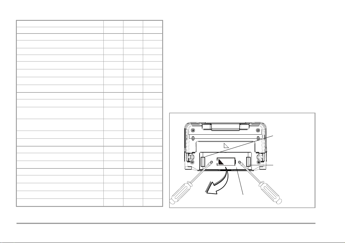
Replacement Fuse
Fuse
Battery Compartment Lid
METRISO INTRO BASE TECH
Article number M550N M550O M550P
Measurements
U = 1000 V
R
INS
R
U = 250, 500 V ✓✓✓
INS
R
U = 50, 100 V — ✓✓
INS
R 10 Ω ... 10 kΩ
RLO 0.17 Ω ... 10 Ω
U 0 ... 1000 V
U 0 ... 500 V
Display Functions
Backlit display
Limit value LED (green/red) for:
Additional acoustic signal, limit value per VDE 0100
LED for dangerous contact voltage
(when switched off)
LCD symbol for external voltage
Battery level display
Special Functions
Discharge capacitive devices under test
Safety shutdown (UBatt < 8 V)
Features
CAT II 1000 V / CAT II I 600 V / CAT IV 300 V
Measuring category CAT II I 600 V / CAT IV 300 V
10 MΩ test resistor
DAkkS calibration certificate
✓
—
✓
✓ —
✓
✓
R
INS RLORINS RLORINS RLO
—
✓
✓
✓
✓
✓ —
✓
—
—
—
✓
✓✓
✓✓
✓
✓✓
✓✓
✓✓
✓✓
✓✓
✓✓
✓✓
✓
✓✓
✓✓
✓✓
1 Insulation and resistance measuring instrument
1 DAkkS calibration certificate (not METRISO INTRO)
1 Set batteries (8 ea. in battery holder) (not METRISO INTRO)
1Carrying strap
1 Alligator clip (not METRISO INTRO)
1 KS17-4 cable set
1 Condensed operating instructions
1 Supplement Safety Information
1 Detailed operating instructions for download from our website
at www.gossenmetrawatt.com
Battery Compartment Lid and Location of the Fuses
(housing bottom)
2 GMC-I Messtechnik GmbH
Page 3
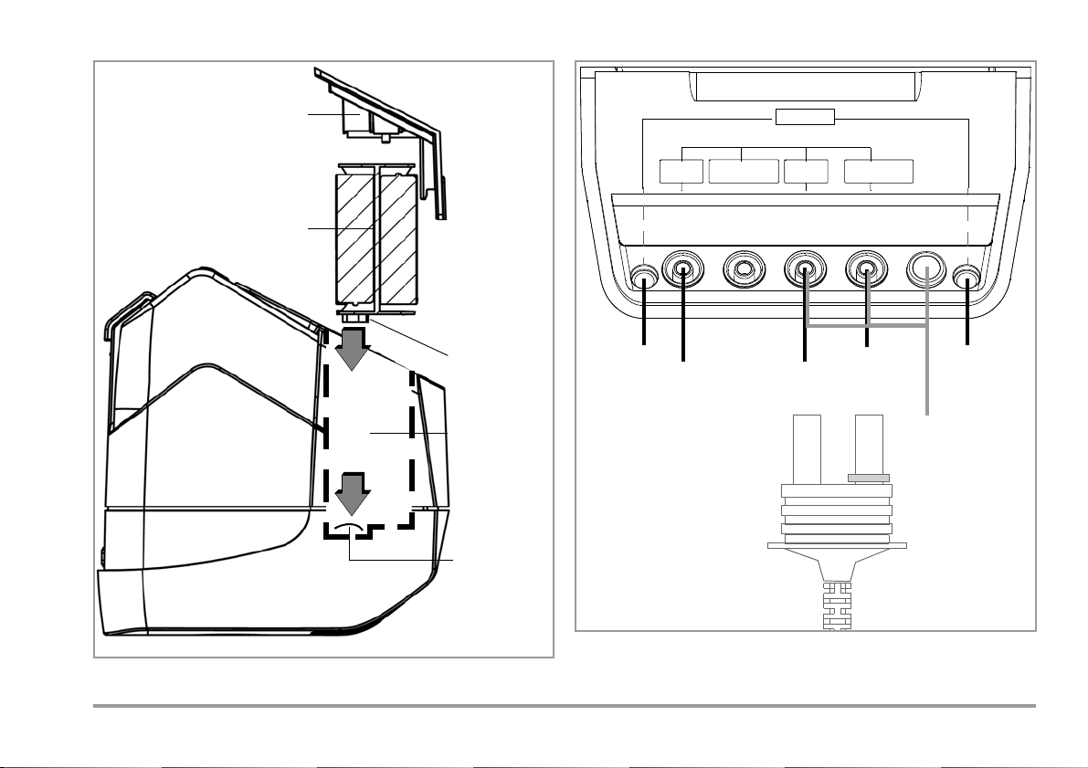
Inserting the Battery Holder (side view) Connections (housing top)
Battery Holder
Battery Compartment Lid
Battery Holder
Contacts
Battery
Contact
Spring
User Interface
Compartment
+
COM
+
COM
SHIELD
Shielded
Cable
Tes t
Resistor*
Tes t
Resistor*
Measuring
Test Pro b e w ith
Control Keys
1
10 MΩ*
Connector with
Shielded Cable,
Option KS-C (Z541F)
(G500/G100G500/G1000)
Connections
GUARD*
* not METRISO INTRO
GMC-I Messtechnik GmbH 3
1
Z550A accessory as option: Test probe with a key for triggering measurement, and
an additional key for illuminating the measuring point, including shielded plug-in
connector cable
Page 4
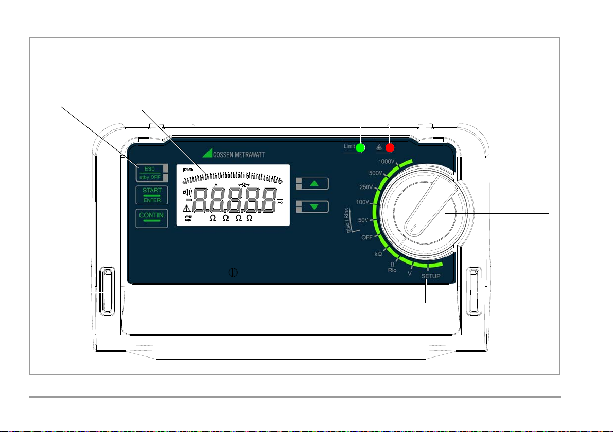
User Interface (Example METRISO TECH)
LCD panel
Start measurement
Parameters transfer
Exit
Activate instrument
Continuous
Scroll down:
Red LED: limit value exceeded
Red LED:
– External voltage with device switched off *
Setup menu SEt
Function
selector switch
Guide for
carrying strap
Guide for
carrying strap
M Vk
TRMS
AC
DC
Rlo>10%
MAN
DATA
STORE
ZERO G
ISO
2500V
1000 V
Tk
1
0
0
k
1
G
1
0
k
1
M
1
0
G
0
1
0
0
0
V
12
0
0
G
1
0
0
M
1
0
M
Green LED: limit value adhered to
– SETUP: parameter selection
– V: voltage type selection
– Rlo: polarity reversal
Scroll up:
– SETUP: parameter selection
– V: voltage type selection
– Rlo: polarity reversal
– Test/Measuring voltage with device switched on
for Riso/Rins,
menu
from standby
state
measurement
R & R
LO
– Discharge voltage for Riso/Rins
* not
METRISO INTRO
4 GMC-I Messtechnik GmbH
Page 5
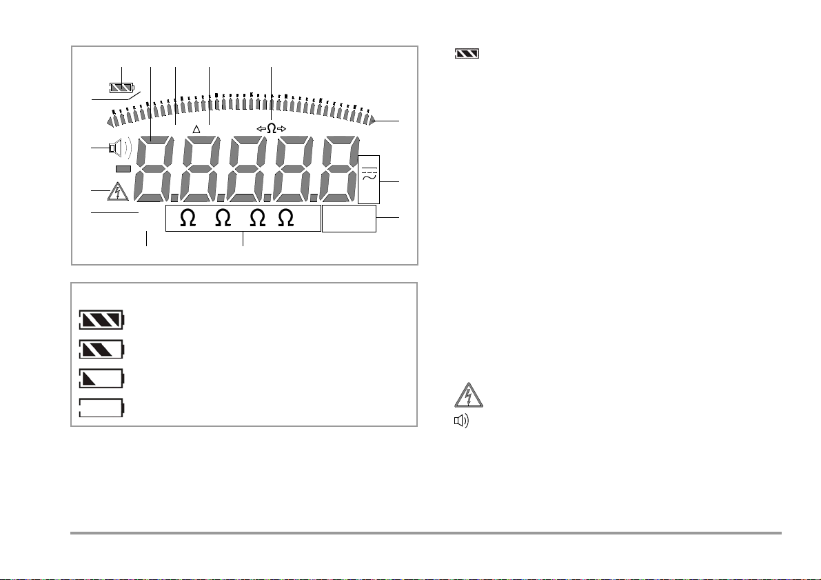
Digital Display Symbols
M
Vk
TRMS
AC
DC
Rlo>10%
MAN
DATA
ZERO
G
ISO
2500V
1000 V
T
k
1
0
0
k
1
G
1
0
k
1
M
1
0
G
0
1
0
0
0
V
1
2
0
0
G
1
0
0
M
1
0
M
6
7
8
1 3
10
9
13
12
4 52
11
On
14
Battery full
Battery OK
Battery weak
Battery (almost) dead, U < 8.5 V
Battery level indicator
GMC-I Messtechnik GmbH 5
1 Battery level indicator
2 Digital display with decimal point and polarity display
3 MAN: Low-resistance measurement:
manual measuring range selection active
4 Rlo: Low-resistance measurement:
special case for automatic low-resistance measure
ment with measurement in both directions of current
flow: both measured values are displayed where ΔRlo > 10%
5 Low-resistance measurement:
polarity reversal display (reversed current flow
direction) Ω→ or ←Ω
6 Analog display pointer: bar graph or pointer,
see A.diSP parameter on page 12
Triangle at display: indicates overranging
7 DC/AC: Selected current type
ISO xxxV:
8
Insulation resistance measurement: selected test voltage
9 Ω V: Unit of measure
10 ZERO:
Cable compensation for low-resistance measurement is
active,
see rLEAd parameter on page 11
11 DATA: Blinks during measurement
Static: measured value is stable
12 Warning regarding dangerous voltage:
13 Acoustic signal (beeper) active for exceeded limit
14 ON Instrument is continuously on
U > 50 V AC/DC
values, see bEEP parameter on page 12
(except with switch in OFF position),
see APOFF parameter on page 12
Page 6

Contents Page Contents Page
1 Applications ...............................................................................7
2 Safety Features and Precautions ..............................................8
3 Initial Start-Up ...........................................................................9
3.1 Battery test ......................................................................................9
3.2 Installing or Replacing Batteries .....................................................9
3.3 Query and Set Device Parameters – SETUP Function ...................10
3.3.1 Paths to the Various Parameters ...............................................................10
3.3.2 Querying Parameters – InFo Menu (as moving letters) ..............................11
3.3.3 Entering Parameters – SEt Menu ...............................................................11
3.3.4 Default Settings .........................................................................................13
4 General Operation ....................................................................14
4.1 Switching On, Monitoring and Switching Off ................................14
4.2 Measured Value Display ................................................................15
5 Measuring Insulation Resistance – R
5.1 Connection ....................................................................................16
5.2 Performing the Measurement .......................................................16
5.3 Ending the Measurement ..............................................................17
Function ............16
iso/Rins
6 Measuring Direct, Alternating and Pulsating Voltage – V Function .....18
Ω/Ω
7 Measuring Resistance – k
Function (METRISO BASE/TECH) .......19
8 Measuring Low-Value Resistance (up to 10 Ohm) – RLO Function 20
8.1
Measurement with Automatic Polarity Reversal – AUTO Function ........... 21
8.2 Measurement with Manual Polarity Reversal – MAN Function .....22
8.3 Taking Measurement Cables and Extension Cables into Account (up
to 10 Ohm) – ZERO Function (Roffset) ...........................................23
Insulation Measuring Instrument ............................................ 23
10 Characteristic Values .............................................................. 24
List of Abbreviations and their Meanings ..................................... 28
11
12 Maintenance ........................................................................... 28
12.1 Battery and Rechargeable Battery Operation ................................28
12.2 Fuses .............................................................................................29
12.2.1Fuse Link – FUSE Message ........................................................................ 29
12.2.2Electronic Fuse
12.3 Housing .........................................................................................30
.....................................................................................................30
13 Recalibration ........................................................................... 30
14 Appendix ................................................................................. 31
14.1 Sample Connection Layouts for Insulation Resistance Measurement ......31
14.2 Attaching the strap to the test instrument ....................................34
14.3 Attaching the Test Probe Holder to the Carrying Strap ................34
14.4 Technical Data for Measurement Cables
(scope of delivery: KS17-4 safety cable set) .................................35
14.5 Optional Accessories (not included) ..............................................36
14.5.1
Application Test Probe for Remote Triggering (Option Z550A) ................................36
15 Repair and Replacement Parts Service
Calibration Center and Rental Instrument Service ............................. 37
16 Product Support ...................................................................... 37
9 Test Resistor for Insulation Measurement for Checking the
6 GMC-I Messtechnik GmbH
Page 7

1 Applications
These instruments fulfills all requirements of applicable European
and national EC directives. We confirm this with the CE mark. The
relevant declaration of conformity can be obtained from GMC-I
Messtechnik GmbH.
METRISO INTRO/BASE/TECH insulation and resistance measuring instruments allow for quick and efficient testing of protective
measures in accordance with DIN VDE 0100, ÖVE-EN 1 (Austria),
NIV/NIN SEV 1000 (Switzerland), and regulations specific to additional countries.
The device is equipped with a microprocessor and complies with
IEC/EN 61557 / VDE 0413 regulations:
Part 1: General requirements
Part 2: Insulation resistance measuring instruments
Part 4: Instruments for the measurement of resistance at
earthing conductors, protective conductors and bonding conductors
Part 10: Combined measuring equipment for testing, measuring
or monitoring protective measures
As well as requirements per VDE 0701-0702:
Repair, modification and inspection of electrical appliances.
The test instrument is especially well suited for:
•Systems set-up
• Initial start-up
• Periodic testing
• Troubleshooting in electrical systems
The following measurements and tests can be performed with the
insulation measuring instruments:
• Insulation resistance
• Low-resistance
• Voltage
The following can also be tested by using a shielded measurement cable:
• Floor covering electrostatic discharge capability
GMC-I Messtechnik GmbH 7
Page 8
2 Safety Features and Precautions
!
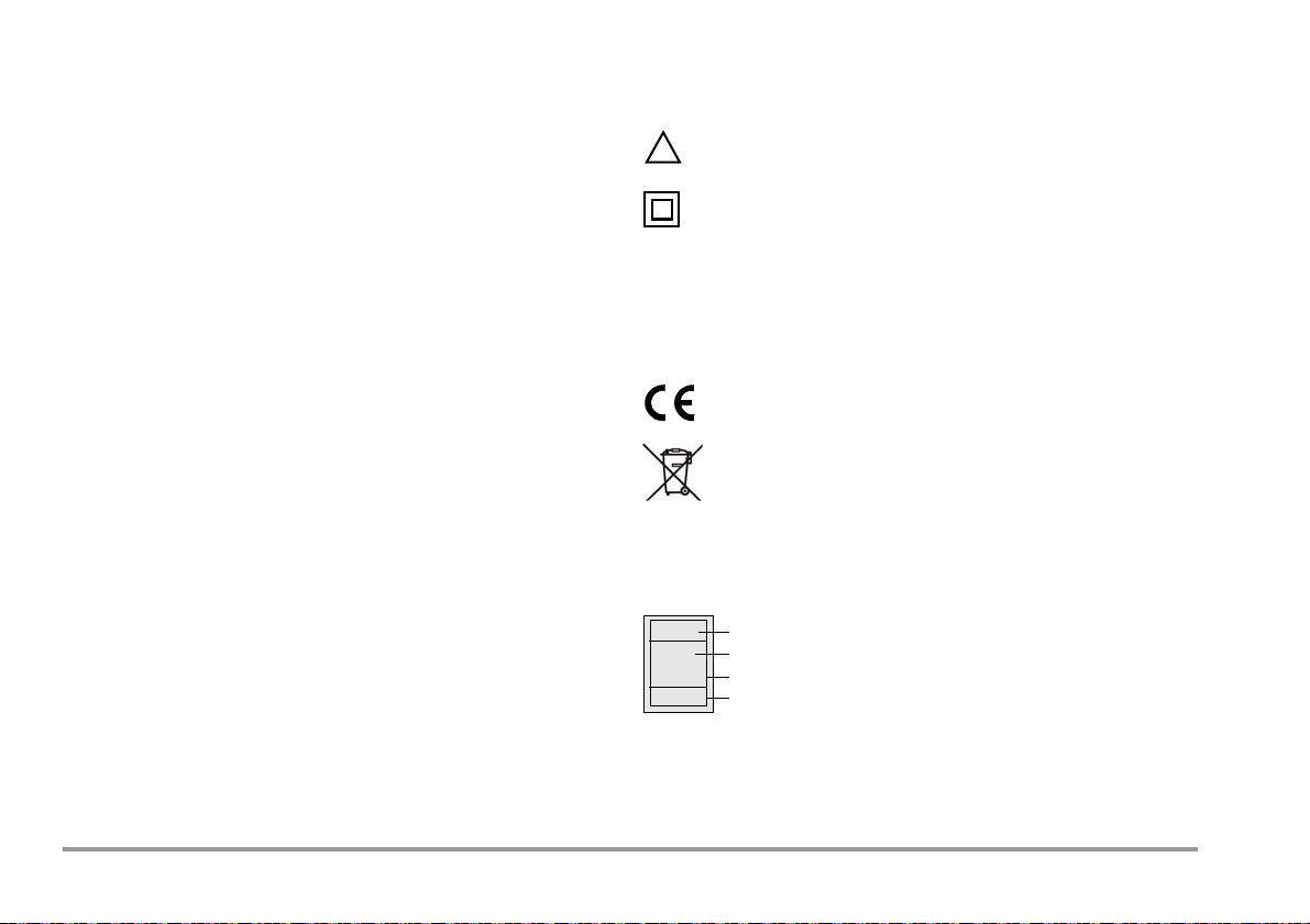
XY123
2013-10
D-K
15080-01-01
Consecutive number
Registration number
Date of calibration (year – month)
Deutsche Akkreditierungsstelle GmbH – calibration lab
The electronic measuring and test instrument is manufactured
and tested in accordance with safety regulations IEC/EN 61010-1
/ VDE 0411-1 and EN 61557. When used for its intended purpose, safety of the operator, as well as that of the instrument, is
assured.
Read the operating instructions thoroughly and carefully before
using your instrument. Follow all instructions contained therein.
The measuring and test instrument may not be placed into service:
• If the battery compartment lid has been removed
• If external damage is apparent
• If connector cable or measuring adapters are damaged
• If the instrument no longer functions flawlessly
• After extraordinary damage due to transport
• After long periods of storage under unfavorable conditions
(e.g. humidity, dust or extreme temperature)
Opening of Equipment / Repair
The equipment may be opened only by authorized service personnel to ensure the safe and correct operation of the equipment
and to keep the warranty valid.
Even original spare parts may be installed only by authorized service personnel.
In case the equipment was opened by unauthorized personnel,
no warranty regarding personal safety, measurement accuracy,
conformity with applicable safety measures or any consequential
damage is granted by the manufacturer.
Meaning of Symbols on the Instrument
Warning concerning a source of danger
(attention: observe documentation!)
Protection class II device
CAT II/ III Device assigned to measuring categories
METRISO INTRO/TECH:
CAT I I 1000 V / CAT III 600 V / CAT IV 300 V
METRISO BASE:
CAT I I I 600 V / CAT IV 300 V
EC mark of conformity
The device and included batteries may not be disposed of with the trash. Further information regarding
the WEEE mark can be accessed on the Internet at
www.gossenmetrawatt.com by entering the search
term “WEEE”.
Calibration Seal (blue seal):
See also “Recalibration” on page 30.
8 GMC-I Messtechnik GmbH
Page 9
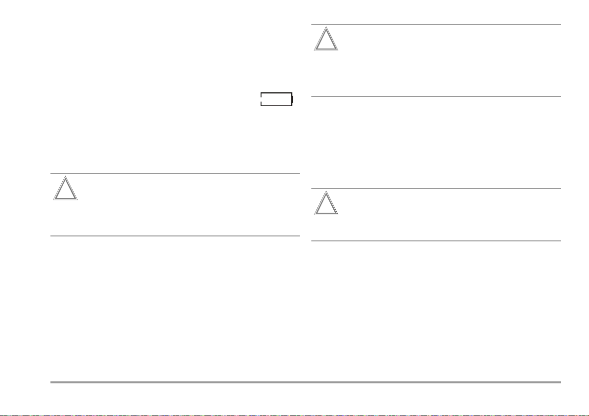
3 Initial Start-Up
Attention!
!
Attention!
!
Attention!
!
3.1 Battery test
Four different battery symbols, ranging from fully depleted to fully
charged, continuously indicate the momentary charge level in the
upper left-hand corner of the display
If battery voltage has fallen below the allowable lower
limit, the pictograph shown at the right appears. The
instrument does not function if the batteries have been depleted
excessively, and no display appears.
3.2 Installing or Replacing Batteries
New batteries must be inserted for initial start-up, or if only one
filled segment remains in the battery symbol.
Before opening the battery compartment (see page 5 for
location), disconnect the instrument from the measuring
circuit (mains) at all poles.
Eight 1.5 V size AA batteries in accordance with IEC LR 6 are
required for operation of the insulation measuring instrument. Use
new alkaline manganese batteries only.
Rechargeable NiCd or NiMH batteries may also be used. These
can only be recharged externally. We recommend rechargeable
NiMH batteries.
Always replace batteries in complete sets.
Dispose of batteries in an environmentally sound fashion.
Ð Loosen both slotted screws for the battery compartment lid
on the back, and remove the lid.
Ð Remove the battery holder and insert eight 1.5 V size AA bat-
teries with correct polarity in accordance with the symbols.
Make sure that all of the batteries are inserted with correct
polarity. If just one battery is inserted with reversed polarity, it will not be recognized by the instrument and may
result in leakage from the batteries.
Ð Push the battery holder into the battery compartment such
that the battery holder’s contacts touch the contact springs at
the bottom of the battery compartment (see drawing on
page 3).
If the battery holder is not inserted as specified, the instrument
cannot be supplied with power.
Ð Replace the battery compartment lid and retighten the
screws.
The instrument may only be placed into service if the
battery compartment lid is securely fastened!
GMC-I Messtechnik GmbH 9
Page 10
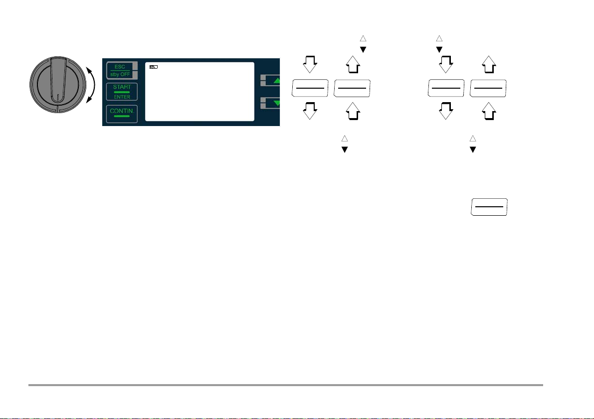
3.3 Query and Set Device Parameters
info
SETUP
bAtt:
uers
ion
1nFo SET
Query Parameter ↓
rlead
APoFF
blight
bEEP
A.d
iSP
0..d
iSP
START
ENTER
Acknowledge
START
ENTER
Set Parameter ↓
←
Main Menus →
ESC
stby OFF
START
ENTER
ESC
stby OFF
– SETUP Function
Ð Turn the rotary switch to the SETUP position.
info appears at the display.
Ð Press ENTER to query battery voltage or firmware version.
Ð Then select the desired operating parameters with the scroll
keys and acknowledge by pressing the ENTER key.
The desired information is displayed in the scroll mode (moving
letters).
3.3.1 Paths to the Various Parameters
10 GMC-I Messtechnik GmbH
Page 11
List of all parameters (alphabetical order)
Note
START
ENTER
START
ENTER
START
ENTER
START
ENTER
START
ENTER
Parameter
0.d iSP
A.d iSP
APoFF
bAtt
bEEP
blight
Com
1nfo
liled
SET
uErS
ion
rlead
Page: Header
13: 0.diSP – Show/Hide Leading Zeros
12: A.diSP – Analog Display: Select Display Mode
12: APoFF – Specified Time for Automatic Shutdown and Continuous ON
11: bAtt – Query Battery Voltage
12: bEEP – Acoustic Indication of Exceeded Limit Values
12: bLiGt – Switching LCD Illumination On/Off
For service purposes only
11: Querying Parameters – InFo Menu (as moving letters)
13: LiLEd – Optical Indication of Limit Value Violations
11: Entering Parameters – SEt Menu
11: vErSion – Query Firmware Version
11: rLEAd – Offset Resistance for Low-Resistance Measurement
3.3.2 Querying Parameters – InFo Menu (as moving letters)
bAtt – Query Battery Voltage
3.3.3 Entering Parameters – SEt Menu
rLEAd – Offset Resistance for Low-Resistance Measurement
Measurement cable ohmic resistance can be subtracted from the
measurement results automatically. Offset must be determined
and saved to memory via the rLEAd parameter to this end.
Ð Connect the measurement cables to the + and COM jacks.
Ð Short circuit the two test probes connected to the measure-
ment cables (including extension cables).
Ð Select the rLEAd parameter and acknowledge by pressing the
ENTER key. Select ZERO and acknowledge by pressing the
START key in order to trigger measurement of offset resistance:
SET rlead
1nFo
zero / Clear
Low-resistance measurement as described in section 8.1 is conducted in both directions with automatic polarity reversal.
If the test probes are not short circuited, the SHort LEAdS
prompt appears at the display.
1nFo bAtt: 12.05 V.
The measurement results, i.e. the resistance of the two measurement cables, are subtracted from future low-resistance measurements as an offset value, and ZERO appears in the footer.
After selecting the CLEAr parameter and acknowledging by
vErSion – Query Firmware Version
pressing the ENTER key, you’re provided with the opportunity of
performing future measurements without using the offset. If this is
1nFo bAtt: uErS ion: 1.0.0
GMC-I Messtechnik GmbH 11
the case, ZERO is no longer displayed. In this case, measurement
cable resistance is included in the measurement.
Page 12
APoFF – Specified Time for Automatic Shutdown and Continuous ON
START
ENTER
START
ENTER
START
ENTER
START
ENTER
START
ENTER
START
ENTER
START
ENTER
START
ENTER
START
ENTER
START
ENTER
START
ENTER
START
ENTER
Shutdown time APoFF can be specified with this parameter. The
instrument is switched off automatically if the measured value
remains unchanged for a long period of time and if none of the
keys or the rotary switch have been activated before specified
APoFF time (entered in minutes) has elapsed.
The selected on-time has as substantial influence on battery service life.
If the on setting is selected, the instrument is set for long-term
measurement and
ON appears at the display to the right of the
battery symbol. In this case, the instrument can only be switched
off manually.
bEEP – Acoustic Indication of Exceeded Limit Values
This parameter allows you to decide whether or not exceeded
limit values will be indicated acoustically.
on = acoustic indication activated
1nFo SET rlead ... bEEP
on / off
(on = default setting)
SET rlead ... ... APoFF
1nFo
10 ... 59 min on
A.diSP – Analog Display: Select Display Mode
One of two different display modes can be selected for the analog
display:
• bArG: bar graph
(10 minutes = default setting)
• Po int: pointer
1nFo
SET rlead ... A.d iSP
bLiGt – Switching LCD Illumination On/Off
Automatic deactivation of display illumination after xx seconds
bArG / Po int
(after the last time the rotary switch is actuated) can be selected in
order to extend the battery service life. As soon as a new measuring function is selected or started, illumination is reactivated.
(po int = default setting)
When set to oFF, illumination is permanently deactivated.
1nFo SET rlead ... ... bligt
15 / 30 / 45 / 90 s off
(15 seconds = default setting)
12 GMC-I Messtechnik GmbH
Page 13

0.diSP – Show/Hide Leading Zeros
START
ENTER
START
ENTER
START
ENTER
START
ENTER
START
ENTER
START
ENTER
ESC
stby OFF
This parameter determines whether or not leading zeros will
appear in the measured value display.
1nFo SET rlead ... 0.diSP
0000.0: with leading zeros (default value)
0.0 : leading zeros suppressed
3.3.4 Default Settings
Previously entered changes can be undone, and default settings
can be restored. This may be advisable under the following circumstances:
• After the occurrence of software or hardware errors
• If you are under the impression that the instrument does not
work correctly
Ð Disconnect the device from the measuring circuit.
Ð Briefly remove the batteries (see also section 3.2).
Ð Press and hold the key,
and reinsert the batteries.
LiLEd – Optical Indication of Limit Value Violations
This parameter allows you to decide whether or not limit value vio-
After hearing two acoustic signals, the instrument has been
restored to its default settings.
lations will be indicated optically.
on = optical indication activated
1nFo
SET rlead ... ... liled
on / off
(on = default setting)
GMC-I Messtechnik GmbH 13
Page 14

4 General Operation
+
C
O
M
S
H
I
E
L
D
KS-C
(Z541F)
Limit
Green
Limit
Red
!
Red
The test leads are connected to the “+” and “COM” jacks.
Measuring High-Value Resistance with the KS-C Probe (Option)
When measuring electrostatic
discharge capacity for floor
coverings, the shielded cable
should also be connected to
the COM and SHIELD jacks (KS-C
accessory set, “cable set consisting of measurement cable
and high-resistance measurement cable for measurements
in the GΩ range”, see diagram). Be sure to observe color coding.
For measuring with the Test Probe for Remote Triggering (Option Z550A)
see section 14.5.1.
4.1 Switching On, Monitoring and Switching Off
If battery voltage falls below the allowable limit value (U < 8 V) the
instrument cannot be switched on, or it is immediately switched
off.
Measurement cannot be started in the resistance measuring
ranges in the event of external voltage.
The instrument only switches itself off automatically after completion of an automatic measuring sequence, and after the predetermined on-time has expired (APOFF parameter in SETUP switch
position, see page 12). On-time is reset to its original value as
defined in the setup menu, as soon as any key or the rotary function switch is activated.
If the instrument is switched off automatically with the rotary
switch in any position other than OFF, it can be reactivated by
pressing the stby OFF key.
14 GMC-I Messtechnik GmbH
The instrument can be switched off manually by turning the rotary
switch to the OFF position.
Optical Indicators
LED Status Function – Cause
Limit value indication
– Measured insulation resistance does not violate the limit
value.
– Measured low-resistance Rlo does not violate the limit
value.
Limit value indication
– Measured insulation resistance has fallen short of the se-
lected limit value.
– Measured low-resistance Rlo does has exceeded the per-
missible limit value.
External voltage when on or off (not M550N) and during discharge
Dangerous voltage of greater than 50 V is present at the measurement inputs:
– Initialization of the (insulation) resistance and
low-resistance measurements is disabled.
– The discharging cycle has not yet been completed,
e.g. residual voltage at capacitive devices under test
Test/Measuring voltage with device switched on
Dangerous voltage of greater than 50 V is present at the measurement inputs.
LCD Status Functions
External voltage when off, and during discharge
Dangerous voltage of greater than 50 V is present at the
measurement inputs:
– Initialization of the insulation resistance and
Display
1
Prerequisite: The LiLEd parameter is set to on (see page 13).
2
Function testing should be executed regularly (see following section on testing
LEDs).
low-resistance measurements is disabled.
– Test voltage applied during insulation measurement
– The discharging cycle has not yet been completed,
e.g. residual voltage at capacitive devices under test
1
1
2
Page 15

Testing the LED which Indicates the Detection of External Voltage
Limit
when Switched Off – OFF Switch Position
Ð Apply a voltage of greater than 50 V (+ and COM jacks).
Ð Turn the rotary switch to the V position.
Ð Read the voltage value at the LCD.
Ð Turn the rotary switch to the OFF position.
Test results: If applied voltage is unchanged and the LED which
indicates the detection of external voltage lights up red, the LED is
OK. In this case, the LED reliably indicates external voltage even
when the instrument is switched off. We recommend executing
this test at regular intervals.
Limit Values for Insulation and Low-Resistance Measurements
METRISO INTRO BASE TECH
)
(M550O) (M550P)
33
33
333
333
3
—
333
3
Limit
R
/ R
ISO
Limit R
INS
LO
50 kΩ @ U
100 kΩ @ U
500 kΩ @ U
1 MΩ @ U
1 MΩ @ U
2 Ω
ISO/UINS
ISO/UINS
ISO/UINS
ISO/UINS
ISO/UINS
(M550N
= 50 V —
= 100 V —
= 250 V
= 500 V
= 1000 V
Acoustic Signals
Limits can also be indicated acoustically by setting the beeP
parameter to on (see page 12).
The loudspeaker symbol appears in this case.
– Low-Resistance Measurement: Signal when RLO < 2 Ω (Continuity test)
– Insulation
Measurement
: Signal
when
R
< limit value
INS
4.2 Measured Value Display
The following appear at the LCD panel:
• Measured value in digital format
• Measured value in analog format as bar graph or pointer
• Unit of measure
Measured values for automatic measuring sequences are
retained at the display as digital values until the next measurement sequence is started, or until automatic shut-off occurs.
If the upper range limit is exceeded, 0L appears at the display,
thus indicating overranging.
If the lower range limit is fallen short of, ur appears at the display,
thus indicating underranging.
Either a bar graph or a pointer can be selected for the analog display (see AdiSP parameter on page 12).
GMC-I Messtechnik GmbH 15
Page 16

5 Measuring Insulation Resistance – Riso/Rins Function
Note
L1
L2
N
PE
L3
R
B
R
E
+
COM
R
ISO
+ COM SHIELD
Rx
0V !
!
R
ISO
R
INS
MAN
DATA
ISO
500V
1
0
0
k
1
G
1
0
k
1
M
1
0
G
1
00
G
1
0
0
M
1
0
M
---
START
ENTER
5.1 Connection
Checking the Measurement Cables
Before performing insulation measurement, the test
probes on the measurement cables should be short-circuited in order to assure that the instrument displays a
value very close to 0 Ω (see section 8). This makes it possible to detect interrupted measurement cables, which
simulate high insulation resistance.
For this instrument,
ching from one insulation resistance measuring range to
another. When further measurements are performed in the
same measuring range, fuse testing is dispensed with for the
sake of a faster test procedure.
Ð Connect the device under test to the + and COM jacks.
Sample connection layouts for insulation resistance measurement are
included in section 14.1. Insulation resistance can only be measured at
voltage-free objects. If mains voltage or external voltage is applied to the
measurement inputs, measurement cannot be started. This is indicated
by the
high-voltage symbol
5.2 Performing the Measurement
Note: Condensation must be ruled out when performing measure-
ments at close to the freezing point.
Ð Select the measuring function and the desired test voltage
with the rotary switch, e.g. R
The momentarily selected test voltage (nominal voltage) appears
in the bottom right-hand corner of the display.
Ð
Start an individual measurement by briefly pressing the
initiate continuous measurement by briefly pressing the
fuse testing
is only performed after swit-
which appears at the display.
iSO
100V.
START
key, or
CONTIN
key.
16 GMC-I Messtechnik GmbH
Page 17

DATA blinks at the display until the measured value has settled in.
Attention!
!
Note
Note
Caution!
M
MAN
DATA
ISO
500 V
1
0
0
k
1
G
1
0
k
1
M
1
0
G
1
0
0
G
1
0
0
M
1
0
M
3.25
U
ISO/INS
M
MAN
DATA
ISO
500 V
3.25
U
I
S
O
/
I
N
S
R
ISO/RINS
= const.
0
2
5
V
5
0
V
5
0
0
V
5.3 Ending the Measurement
Individual measurement: Measurement is ended automatically as
soon as the measured value has settled in.
Continuous measurement is ended by briefly pressing the ESC key.
In either case, the measured value is retained at the 7-segment
display. When discharging begins, the unit of measure for the bar
graph changes from Ω to V. The length of the bar graph is continuously reduced as voltage at the device under test drops.
Special Case: Capacitive Devices Under Test
Do not touch the instrument’s terminal contacts during
insulation resistance measurements!
If nothing has been connected to the terminal contacts, or if a
resistive load component has been connected for measurement,
your body would be exposed to a current of approximately 1 mA
at a voltage of 1000 V. The resulting electrical shock is not life
endangering. However, the noticeable shock may lead to injury
(e.g. resulting from a startled reaction etc.).
When an insulation resistance measurement has been performed
on a capacitive object it is automatically discharged by the instrument. Contact between the object and the instrument must nevertheless not be interrupted. Do not disconnect until:
•The caution LED (> 50 V) is no longer illuminated
If measurement is performed at a capacitive object such
as a long cable, it becomes charged with up to approx.
1000 V (test voltage)! Touching such objects is life endangering!
•The high-voltage symbol is no longer displayed
Three-Phase Systems
All conductors (L1, L2, L3 and N) must be measured
•The analog bar graph has dropped to a value of less than 50 V
against PE!
The instrument’s batteries are exposed to excessive
stress during insulation resistance measurement. For this
reason it’s advisable to perform individual rather than
GMC-I Messtechnik GmbH 17
continuous measurements.
Page 18

6 Measuring Direct, Alternating and
Note
L1
L2
N
PE
L3
R
B
R
E
Max.
1.2 kV
U
+
COM
+ COM SHIELD
V
TRMS
AC
DC
0
1
0
0
0
V
390
1
1
0
V
2
3
0
V
DC / AC
DC
AC
V
Pulsating Voltage – V Function
You can measure direct voltage, as well as sinusoidal alternating
voltage with frequencies ranging from 45 to 65 Hz with this test
instrument.
Ð Select the V measuring function with the rotary switch.
Ð Select the desired voltage type with the scroll keys:
direct voltage (DC),
alternating voltage (AC TRMS)
or pulsating voltage (DC + AC TRMS)
Ð Connect the measurement cables to the + and COM jacks.
Ð Contact the measuring point with both test probes.
The measured value is displayed directly (without pressing the
START key) in analog format at the bar graph and in digital format
at the 7-segment display.
Ð After completing the measurement, switch the instrument off
by turning the rotary switch to the OFF position.
The ESC, START and CONTIN. keys are disabled in this case.
Input impedance for the voltage measuring range is
10 MΩ.
18 GMC-I Messtechnik GmbH
Page 19

7 Measuring Resistance – kΩ/Ω Function
kΩ
+
C
O
M
Rx
Rx
0V !
!
DATA
20.4
0
1
0
0
0
START
ENTER
(METRISO BASE/TECH)
Ð Connect the device under test to the + and COM jacks.
Resistance can only be measured at voltage-free objects. If mains
voltage or external voltage is applied to the measurement inputs,
measurement cannot be started.
This is indicated by the high-voltage symbol which appears at the
display.
Ð Select measuring function kΩ or Ω with the rotary switch.
Ð Start an individual measurement by briefly pressing the START
key, or initiate continuous measurement by briefly pressing
the CONTIN key.
DATA blinks at the display until the measured value has settled in.
GMC-I Messtechnik GmbH 19
Page 20

8 Measuring Low-Value Resistance (up to 10 Ohm)
Attention!
!
Note
Attention!
!
+
COM
R
LO
+ COM SHIELD
R < 10 Ω
R
LO
Rx
0V !
!
R
LO
AUTO
Ω→
¬Ω
---
Rlo
START
ENTER
– RLO Function
According to the regulations, the measurement of low-value resistance at protective conductors, earth conductors or equipotential
bonding must be performed with (automatic) polarity reversal of
the test voltage, or with current flow in one or the other direction.
In the measuring function RLO, measurements are performed with currents about 200 mA.
Please check before measuring whether your DUT or
your circuit is designed for these high current values.
Connection
Low-value resistance can only be measured at voltagefree objects.
Ð Connect the device under test to the + and COM jacks.
Ð Select the Rlo measuring function with the rotary switch.
The measurement cannot be started until the test probes
are in contact with the device under test.
20 GMC-I Messtechnik GmbH
If voltage is present at the device under test (U > 10 V),
the display is switched to voltage measurement. The display is not returned to low-resistance measurement until
voltage is less than approximately 8 V. If resistance is
greater than 10 Ω, OL pears at the display.
Page 21

Ω→
←Ω
ΔRlo>10%:
←Ω & Ω
→
AUTO: Ω→
DATA
00.1
DATA
00.7
Rlo
07._0.1
Δ Rlo>10%
Ω→
Rlo ←Ω
DATA
Limit
< Limit R
LO
= OK 3
←Ω
ΔRlo ≤ 10% ? ←Ω→
ΔRlo > 10% ? ←Ω & Ω→
Measurement Types
You can choose one of two different types of measurement:
• Measuring sequence with automatic polarity reversal (reversal
of current flow direction)
• Manual measurement with specified current flow direction
8.1 Measurement with Automatic Polarity Reversal – AUTO Function
Automatic polarity reversal is selected as a default value. MAN
does not appear at the display.
Ð Start measurement in both current flow directions by briefly
pressing the START key for one-time polarity reversal or start
continuous measurement for permanent polarity reversal by
briefly pressing the CONTIN. key.
After the measuring sequence has been started, the instrument performs
measurement with automatic polarity reversal, first with current flow in
one direction (
until the measured value has settled in. The larger (worst) measured value
is displayed.
Difference > 10%
If, during measurement with automatic polarity reversal, the difference
between
both polarities (current flow directions) are displayed separately (separated by an underscore). ΔRlo>10% appears at the display.
Limit Value Indication
If the measured value is less than or equal to 2 Ω, the Limit LED
lights up green. If the measured value is greater than 2 Ω, the LED
lights up red. As a prerequisite, the LiLED parameter must be set
to “on” (see page 13).
Resistances which do not demonstrate a stable value until after a
“settling in period” should not be measured with automatic polarity reversal. Measurement with automatic polarity reversal may
Ω→
Ω→
), and then in the other (←Ω).
←Ω→
appears at the display.
DATA
blinks at the display
and ←Ω is greater than 10%, the resistance values for
lead to varying and/or inflated measurement values, and thus to
an ambiguous reading.
GMC-I Messtechnik GmbH 21
Page 22

8.2 Measurement with Manual Polarity Reversal
DATA
ZERO
00.1
DATA
ZERO
00.7
Rlo Ω→
Rlo ←Ω
Ω→
←Ω
MAN: Rlo Ω→
MAN: Rlo ←Ω
MAN
MAN
– MAN Function
In order to determine whether or not the obtained results are independent of current flow direction, measurement can be performed separately for both directions.
Ð Press the
sired current flow direction:
MAN and Ω→ or MAN and ←Ω appear at the display.
Ð Start an individual measurement by briefly pressing the START
key, or initiate continuous measurement by briefly pressing
the CONTIN key.
DATA blinks at the display until the measured value has settled in.
Differing results indicate voltage at the device under test (e.g.
thermovoltage or unit voltages).
Measurement results can be distorted by parallel connected
impedances at load current circuits and by equalizing current,
especially in systems which make use of “overcurrent protection
devices” (previous neutralization) without an isolated protective
conductor. Resistances which change during measurement (e.g.
inductance), or a poor contact, can also cause distorted measurements.
Examples of resistances whose values may change during measurement include:
– Incandescent lamp resistance with changing values caused
by warming due to measuring current
– Resistances with a large inductive component
In order to assure unambiguous measurement results, causes of
error must be located and eliminated.
scroll keys to this end, depending upon the de-
22 GMC-I Messtechnik GmbH
Page 23

8.3 Taking Measurement Cables and Extension Cables into
Note
+
COM
10M
Ω
+ COM SHIELD
R
ISO/RINS
10 MΩ
METRISO BASE
METRISO TECH
Account (up to 10 Ohm) – ZERO Function (Roffset)
Measurement cable ohmic resistance can be subtracted from the
measurement results automatically. Proceed as follows:
Ð With the switch in the SETUP position and the SET menu at the
display, select the rLEAd parameter. Refer to page 11 for further instructions.
During future low-resistance measurements for which cable resistance is to be taken into account, ZERO appears at the display
and cable resistance R
measurement as described above in the preceding pages.
is subtracted. Perform low-resistance
Offset
9 Test Resistor for Insulation Measurement for
Checking the Insulation Measuring Instrument
According to section 5.3.1.2 of VDE 0105-100 (EN 50110-1), the
following applies: “These measuring instruments must be tested
before, and if applicable after use.”
The two outermost jacks on the connection panel must be connected to each other internally via a 10 MΩ test resistor to this
end.
The sum of test resistor and cable resistance (for both cables),
including test probes, amounts to 10 MΩ ±5%. This value allows
for quick self-testing.
The cable resistance R
under parameter rLEAd can only be deleted under this
parameter by selecting setting CLEAr, see page 11.
which is stored in menu SET
Offset
GMC-I Messtechnik GmbH 23
Ð Connect the measurement cables to the + and COM jacks.
Ð Insert the test probes into the above described jacks.
Ð Select the R
as well as the desired test voltage, e.g. R
Ð Press the start key and view the measurement results.
measuring function with the rotary switch,
iSO/iNS
iSO
100V.
Page 24

10 Characteristic Values
Meas.
Qty.
UiSO Range Measuring Range
100 k 10.0 kΩ ... 99.9 kΩ 0.1 k
1 M 100 kΩ ... 999 kΩ 1 k
10 M 1.00 MΩ ... 9.99 MΩ 10 k
RINS
BASE/TECH: 50 V
BASE/TECH: 100 V
INTRO: 250 V ... 1000 V
BASE: 250 V / 500 V
100 M 10.0 MΩ ... 99.9 MΩ 100 k
1 G 100 MΩ ... 999 MΩ 1 M
10 G 1.00 GΩ ... 9.99 GΩ 10 M
100 G 10.0 GΩ ... 99.9 GΩ 100 M ±(8% rdg. + 3 d) 3)±(10% rdg. + 3 d)
TECH: 250 V / 500 V / 1000 V
200 G 100 GΩ ... 199 GΩ 1 G ±(25% rdg. + 5 d) 3)±
100 V 10.0 V ... 99.9 V 0.1 V
500 V 100 V ... 510 V
100 V 10.0 V ... 99.9 V 0.1 V
1000 V 100 V ... 999 V
AC/
DC
U
METRISO BASE
METRISO INTRO
METRISO TECH
RLO 10 Ω 0.17 ... 9.99 Ω
R
METRISO TECH
Display range as of 01.0
1)
Display range up to 600 V
2)
Display range up to 1.2 kV
3)
the indicated accuracy is only achieved with the shielded high-resistance measuring cable KS-C (article no. Z541F)“
4)
does not conform to DIN EN 61557-2
5)
up to 5 Ω
METRISO BASE
100 Ω 10.0 ... 99.9 Ω 0.1 Ω
1 kΩ 100 ... 999 Ω 1 Ω
Ω
10 kΩ 1.00 ... 9.99 kΩ 10 Ω
Resolution
1)
1 V
2)
1 V
0.01 Ω4 V < U0
Open-Circuit
Voltage U
0max
Te st
Current
Intrinsic Uncertainty
Measuring
Uncertainty
50 V /100 V:
1.25 U
ISO
IN = 1 mA
±(5% rdg. + 3 d) ±(7% rdg. + 3 d)
250 V /
500 V /
1000 V:
1.1 U
I
≤ 5 mA
K
ISO
(50% rdg. + 20 d)
— ±(2.5% rdg. + 3 d) ±(5% rdg. + 3 d)
— ±(2.5% rdg. + 3 d) ±(5% rdg. + 3 d)
< 6 V
U0 max. 15 V
200 mA ≤ I
I ≤ 260 mA
1 mA ≤ I
I ≤ 1,3 mA
±(2.5% rdg. + 3 d) ±(5% rdg. + 3 d)
±(2.5% rdg. + 3 d) ±(5% rdg. + 3 d)
Overload
Capacity
METRISO BASE:
600 V AC/DC
METRISO INTRO
METRISO TECH:
3)
3) 4)
600 V AC/DC
1000 V AC/DC
METRISO BASE:
600 V AC/DC
METRISO INTRO
METRISO TECH:
1000 V AC/DC TRMS
METRISO BASE:
600 V AC/DC
METRISO TECH
1000 V AC/DC TRMS
TRMS
TRMS
TRMS
TRMS
TRMS
TRMS
24 GMC-I Messtechnik GmbH
Page 25

Reference Conditions
Reference temperature+ 23 °C ±3 K
Relative humidity 40 ... 75%
Measured quantity
frequency 45 Hz ... 65 Hz
Measured quantity
waveform Sine, deviation between TRMS and
rectified value < 1%
Battery voltage 9.5 V ±0.1 V
Test resistance 10 MΩ±1%
Electrical Safety
Standard
VDE regulation VDE 0411, part 1, 1994-03
Protection class II
Pollution degree 2
Measuring category METRISO INTRO/TECH:
CAT II 1000 V / CAT III 600 V / CAT IV 300 V
METRISO BASE:
CAT I I I 600 V / CAT IV 300 V
Fuses
Fuse link FF315mA/1000V, effective in all resis-
tance measuring ranges, 1 additional
replacement fuse in the battery compartment
Elektronic fuse for protecting low-resistance and resis-
tance measurement R
LO
and R
Power Supply
Batteries 8 ea. 1.5 V mignon cells (8 ea. size AA)
(alkaline manganese per IEC LR14)
or 8 rechargeable NiMH batteries (must be
recharged externally)
Nominal range of use 8.5 ... 12 V
Battery test Battery capacity display with battery sym-
bol in 4 segments: .
Querying of momentary battery voltage via
menu function.
Battery saver circuit Automatic shutdown of display illumination
Service life For R
Safety shutdown If supply voltage is too low, the instrument
after 15 second s (after the last time the
rotary switch is actuated) can be set via
the blight parameter.
The test instrument is automatically
switched to the standby mode*
when the
measured value remains unchanged and none
of the controls are activated during this time.
* Specified time “APoFF” (entered in minutes)
adjustable via SETUP menu (default setting
approx. 10 min).
(1000 V / 1 MΩ) and RLO with 20
ISO
second on-time and 1 measurement each
for a duration of 5 seconds
– With batteries (alkaline manganese):
900 measurements
– With rechargeable batteries (2000 mAh):
850 measurements
is switched off, or cannot be switched on.
When the rotary switch is set to the OFF
position, the instrument is completely disconnected from the batteries (after
approximately 10 seconds).
GMC-I Messtechnik GmbH 25
Page 26

Electromagnetic Compatibility (EMC)
!
Interference emission EN 61326-1:2006 class B
Interference immunity EN 61326-1:2006
Ambient Conditions
Accuracy
temperature range 0 ... +40 °C
Operating temperature –10 ... +50 °C
Storage temp. range –25 ... +70 °C (without batteries)
Relative humidity Up to 75%
(max. 85% during storage/transport),
no condensation allowed
Elevation Max. 2000 m
Calibration interval 1 year (recommended)
Mechanical Design
Dimensions 225 x 130 x 140 mm
Weight Approx. 1.4 kg with batteries
Protection Housing: IP 52, measurement cables and
connectors: IP 40 per DIN VDE 0470,
part 1 / EN 60529,
housing category 2
Extract from table on the meaning of IP codes
IP XY
st
(1
digit X)
2 ≥ 12.5 mm dia. 2 Dripping (at 15° angle)
3 ≥ 2.5 mm dia. 3 Spraying water
4 ≥ 1.0 mm dia. 4 Splashing water
5 Dust protected 5 Jet-water
6 Dust-proof 6 Powerful water jets
Protection Against
Foreign Object Entry
IP XY
(2nd digit Y)
Protection Against
Penetration by Water
Displays
Digital display With additional bar graph or pointer
depending on selection with a.disp
parameter, backlit (transflective);
leading zeros can be suppressed at the
digital display depending on 0.disp
parameter;
overranging indicated with 0L at display;
dimensions: 65 x 36 mm
Limit LED LED lights up red to indicate an exceeded
limit value
LED lights up green to indicate adherence
to the limit value
LED LED lights up red to indicate:
– the presence of an external voltage
bevore insulation testing
with the device switched on or off
(device switched off not with M550N)
– the presence of the test/measuring voltage
during (insulation) measurement (U > 50 V)
the presence of a residual voltage
after insulation testing (U > 50 V)
with the device switched on or off
at LCD Detection of external voltage at the LCD
with the device switched on where U DC >
50 V and U AC > 40 V (50 Hz) for all measuring functions
(U > 50 V)
26 GMC-I Messtechnik GmbH
Page 27

100
Ux/V
R
x
/kΩ
U
N
= 100 V
0
20
40
60
80
100
250
Ux/V
R
x
/kΩ
U
N
= 250V
0
50
100
150
200
250
Display Values in Consideration of Measuring Uncertainty
Table for determining minimum display values for insulation resistance in consideration of the instrument’s measuring uncertainty.
Limit Value
020 kΩ 025 kΩ
100 kΩ 111 kΩ 100 MΩ 111 MΩ
200 kΩ 219 kΩ 200 MΩ 219 MΩ
500 kΩ 541 kΩ 500 MΩ 541 MΩ
0.20 MΩ 0.25 MΩ
0.50 MΩ 0.57 MΩ
1.00 MΩ 1.11 MΩ 1.00 GΩ 1.11 GΩ
2.00 MΩ 2.19 MΩ 2.00 GΩ 2.19 GΩ
5.00 MΩ 5.41 MΩ 5.00 GΩ 5.41 GΩ
10.0 MΩ 11.1 MΩ 10.0 GΩ 11.1GΩ
20.0 MΩ 21.9 MΩ 20.0 GΩ 22.6 GΩ
50.0 MΩ 54.1 MΩ 50.0 GΩ 55.9 GΩ
Minimum
Display Value
Limit Value
Minimum
Display Value
Voltage at Device Under Test During Insulation Resistance
Measurement
Measuring voltage Ux at the device under test depending upon its
resistance R
at nominal voltage UN = 100, 250, 500 and 1000 V:
x
Table for determining maximum display values for low-value resistance in consideration of the instrument’s measuring uncertainty.
Limit Value
0.15 Ω 0.11 Ω
0.20
Ω 0.16 Ω 5.00 Ω 4.72 Ω
0.50 Ω 0.44 Ω 10.0 Ω 9.47 Ω
1.00 Ω 0.92 Ω 20.0 Ω 17.7 Ω
2.00 Ω 1.87 Ω 50.0 Ω 44.7 Ω
GMC-I Messtechnik GmbH 27
Maximum
Display Value
Limit Value
Maximum
Display Value
Page 28

11 List of Abbreviations and their Meanings
0
100
200
300
400
500
500
U
N
= 500V
Ux/V
R
x
/kΩ
0
200
400
600
800
1000
1
U
N
= 1000V
Ux/V
R
x
/MΩ
Voltage
U
ISO
U AC/DC Measured voltage (sinusoidal alternating voltage)
Test voltage or nominal voltage
Resistance
LIMIT Limit value for insulation resistance or low-value resis-
tance
Offset Correction value for measurement cable resistance
R
ISO
R
LO
Insulation resistance
Low-value resistance (cable resistance)
Fuse
FUSE “Blown fuse” message
12 Maintenance
12.1 Battery and Rechargeable Battery Operation
When only one filled segment remains in the battery symbol,
install a new set of batteries or charge the rechargeable batteries.
Check to make sure that no leakage has occurred at batteries or
28 GMC-I Messtechnik GmbH
rechargeable batteries at short, regular intervals, or after the
instrument has been in storage for a lengthy period of time.
Page 29

Note
Prior to lengthy periods of rest (e. g. holiday), we recom-
Attention!
!
Attention!
!
mend removing the (rechargeable) batteries. This helps to
prevent excessive depletion or leakage of batteries,
which, under unfavourable circumstances, may cause
damage to the instrument.
If leakage has occurred, the electrolyte must be carefully and
completely removed with a damp cloth before installing new batteries.
Replacing the Batteries
See section 3.2 and section 12.3.
12.2 Fuses
If a fuse has blown due to overload, a corresponding message
error appears at the LCD panel. The instrument’s voltage measuring ranges are nevertheless still functional.
12.2.1 Fuse Link – FUSE Message
This fuse is active in all resistance measuring ranges except for
voltage measurement. A replacement fuse is included in the battery compartment (FF315mA/1000V).
Disconnect the instrument from the measuring circuit before opening the battery compartment lid in order to replace the fuse (refer to page 5 for location)!
Checking the Fuse
If a resistance measuring range is selected with the rotary switch
with a blown or defective fuse in the instrument, and if the instrument is turned on with the switch in this position, fuse appears at
the LCD. Prerequisite: The + and COM measurement jacks are not
short circuited.
After eliminating the cause of error and replacing the defective
fuse, the fuse message is cleared after the instrument has once
again been switched on.
Severe damage to the instrument may occur if incorrect
fuses are used.
Only original fuses from GMC-I Messtechnik GmbH assure required protection by means of suitable blowing
characteristics.
Short-circuiting of fuse terminals or the repair of fuses is
prohibited!
The instrument may be damaged if fuses with incorrect
ampere ratings, breaking capacities or blowing characteristics are used!
Replacing the Fuse
Ð Open the battery compartment lid by loosening the two
screws.
Ð Remove the defective fuse and insert a new one. A replace-
ment fuse is included in the battery compartment.
Ð Insert the new fuse.
Ð Replace the battery compartment lid and retighten the
screws.
GMC-I Messtechnik GmbH 29
Page 30

12.2.2 Electronic Fuse
Pb Cd Hg
This fuse protects low-resistance (Rlo) and resistance measurements (kΩ) from overloading (electronic hardware circuit).
„EL.Fu“ appears when the fuse blows.
Ð Eliminate the cause of overloading. This error message must
be cleared by switching to OFF position.
12.3 Housing
No special maintenance is required for the housing. Keep outside
surfaces clean. Use a slightly dampened cloth or a plastic cleaner
for cleaning. Avoid the use of cleansers, abrasives or solvents.
Return and Environmentally Sound Disposal
The instrument is a category 9 product (monitoring and control
instrument) in accordance with ElektroG (German electrical and
electronic device law). This device is subject to the RoHS directive. Furthermore, we make reference to the fact that the current
status in this regard can be accessed on the Internet at
www.gossenmetrawatt.com by entering the search term WEEE.
We identify our electrical and electronic devices in
accordance with WEEE 2012/19/EU and ElektroG
using the symbol shown at the right per DIN EN 50419.
These devices may not be disposed of with the trash.
Please contact our service department regarding the return of old
devices (see address in section 15).
If you use
ries which no longer function properly, they must be duly disposed of in
compliance with the applicable national regulations.
Batteries or rechargeable batteries may contain harmful substances or
heavy metal such as lead (PB), cadmium (CD) or mercury (Hg).
batteries
or
rechargeable batteries
in your instrument or accesso-
They symbol shown to the right indicates that batteries or
rechargeable batteries may not be disposed of with the
trash, but must be delivered to collection points specially
provided for this purpose.
13 Recalibration
The measuring tasks performed with your instrument, and the
stressing it’s subjected to, influence aging of its components any
may result in deviation from the specified levels of accuracy.
In the case of strict measuring accuracy requirements, as well as
in the event of use at construction sites with frequent stress due
to transport and considerable temperature fluctuation, we recommend a relatively short calibration interval of once per year. If your
instrument is used primarily in the laboratory and indoors without
considerable climatic or mechanical stressing, a calibration interval of once every 2 to 3 years is sufficient as a rule.
During recalibration* at an accredited calibration laboratory (DIN
EN ISO/IEC 17025), deviations from traceable standards demonstrated by your measuring instrument are documented. Ascertained deviations are used to correct displayed values during later
use of the instrument.
We would be happy to perform DAkkS or factory calibration for
you at our calibration laboratory. Further information is available at
our website:
www.gossenmetrawatt.com (→ Company → DAkkS Calibration
Center or → FAQs → Question and Answers Regarding Calibration).
Recalibration of your instrument at regular intervals is essential for
the fulfillment of requirements according to quality management
systems per DIN EN ISO 9001.
* Examination of the specification, as well as adjustment, are not included in calibra-
tion. However, in the case of our own products, any required adjustment is performed and adherence to the specification is confirmed.
30 GMC-I Messtechnik GmbH
Page 31

14 Appendix
L1
L2
L3
N
PE
Between each active conductor and ground
L1
L2
L3
PEN
Between each active conductor and the PEN conductor
L1
L2
L3
N
PE
Between each active conductor (phase and neutral
conductors) and ground
L1
L2
L3
PEN
Between each active conductor and the PEN conductor
14.1 Sample Connection Layouts for Insulation Resistance Measurement
Insulation Resistance Measurement per DIN VDE 0100, Part 600
GMC-I Messtechnik GmbH 31
Page 32

Insulation Resistance Measurement in Different Types of Systems
TN–S
• With or without consumer
•N – PE, separately
TN–C
• With or without consumer
• N – PE, together
TT
• With or without consumer
3-phase current (switched at all poles)
32 GMC-I Messtechnik GmbH
Page 33

Caution:
– Open the overcurrent protective device
– Disconnect the N conductor
– Jumper the L and N conductors
– Insulation measurement between L conductors and N to PE
– Device switch can be open – if single-pole
In the distributor: individual and combined measurements
GMC-I Messtechnik GmbH 33
Page 34

14.2 Attaching the strap to the test instrument
Front
Feed the strap through from the front
of the test instrument and secure it
with the slotted screw (M3).
Back
1
Bottom Right
Detach the strap from the instrument:
Turn out the slotted screw (M3) at the
bottom.
Bottom Left
Strap
Clasp
Clasp
Front View
2
Slide the strap through the test probe
holder.
Eyelet for Attachment to Tester (METRISO ...)
Side View
14.3 Attaching the Test Probe Holder to the Carrying Strap
34 GMC-I Messtechnik GmbH
Page 35

14.4 Technical Data for Measurement Cables
Attention!
!
3
Front
Feed the strap through from the front
of the test instrument and secure it
with the slotted screw (M3).
Back
(scope of delivery: KS17-4 safety cable set)
Electrical Safety
Maximum rated voltage 600 V
Measuring category
Max. rated current: 1 A 1 A 16 A
With safety cap attached
Without safety cap ——
CAT IV CAT III CAT II
1000 V
1000 V
••
Ambient Conditions (EN 61010-031)
Temperature –20 °C ... + 50 °C
Relative humidity Max. 80%
Pollution degree
2
Using the KS17-4
—
•
GMC-I Messtechnik GmbH 35
Observe the instrument’s maximum values for electrical safety.
Measurements per DIN EN 61010-031 may only be performed in environments in accordance with measuring
categories III and IV with the safety cap attached to the
test probe at the end of the measurement cable.
In order to establish contact inside 4 mm jacks, the safety caps
have to be removed by prying open the snap fastener with a
pointed object (e.g. the other test probe).
Page 36

14.5 Optional Accessories (not included)
(G500/G1000)
START/STOP SHIELD COM
Option Z550A
+
ISO Calibrator 1 (material no. M662A)
Calibration adapter for testing the accuracy of instruments used for measuring insulation resistance and
low-resistance for test voltages up to 1000 V (per VDE
0413, parts 1, 2, 4 and 10)
Test Probe for Remote Triggering
(material no. Z550A)
Optional plug-on measurement cable with a triggering
key on the test probe and an additional key for illuminating the measuring point, including shielded, plug-in
connector cable.
KS-C (material no. Z541F)
Cable set consisting of measurement cable and
shielded high-resistance measurement cable for measurements in the GΩ range
14.5.1
Application Test Probe for Remote Triggering (Option Z550A)
When inserting
the 3-pole plug,
make sure that
KY95-3 (material no. Z110J)
(
METRISO BASE/TECH: scope of delivery 1 piece)
Alligator clips (1 pair) for KS17-4 and KS-C
1081 probe (material no. GTZ3196000R0001)
Triangular probe for floor measurements per EN 1081,
DIN VDE 0100-600 (Standing-Surface Insulation)
the jack plug is
inserted in the
START/STOP
position. Press
and align the 3pole plug such
that it is placed
flush on the connection terminal.
KS24 (material no. GTZ3201000R0001)
Cable set consisting of a 4 m long extension cable with
a permanently attached test probe at one end and a
contact protected socket at the other end, and 1 alligator clip which can be plugged onto the test probe
This is the only
way to assure
that the three
contacts of the
jack plug are
properly connected with the command cables.
36 GMC-I Messtechnik GmbH
Page 37

15 Repair and Replacement Parts Service
Calibration Center* and Rental Instrument Service
If required please contact:
GMC-I Service GmbH
Service Center
Thomas-Mann-Str. 20
90471 Nürnberg, Germany
Phone: +49 911 817718-0
Fax: +49 911 817718-253
e-mail: service@gossenmetrawatt.com
www.gmci-service.com
This address is only valid in Germany.
Please contact our representatives or subsidiaries for service in
other countries.
* DAkkS Calibration Laboratory for Electrical Quantities
accredited per DIN EN ISO/IEC 17025:2005
Accredited quantities: direct voltage, direct current value, direct current resistance,
alternating voltage, alternating current value, AC active power, AC apparent power,
DC power, capacitance, frequency, temperature
D-K-15080-01-01
Competent Partner
GMC-I Messtechnik GmbH is certified in accordance with
DIN EN ISO 9001:2008.
Our DAkkS calibration laboratory is accredited by the Deutsche
Akkreditierungsstelle GmbH (National accreditation body for the
Republic of Germany) in accordance with DIN EN ISO/
IEC 17025:2005 under registration number D-K-15080-01-01.
We offer a complete range of expertise in the field of metrology:
from test reports and proprietary calibration certificates right on up to
DAkkS calibration certificates.
Our spectrum of offerings is rounded out with free test equipment
management.
An on-site DAkkS calibration station is an integral part of our service
department. If errors are discovered during calibration, our specialized personnel are capable of completing repairs using original
replacement parts.
As a full service calibration laboratory, we can calibrate instruments from other manufacturers as well.
16 Product Support
If required please contact:
GMC-I Messtechnik GmbH
Product Support Hotline
Phone: +49 911 8602-0
Fax: +49 911 8602-709
e-mail support@gossenmetrawatt.com
GMC-I Messtechnik GmbH 37
Page 38

38 GMC-I Messtechnik GmbH
Page 39

GMC-I Messtechnik GmbH 39
Page 40

Edited in Germany • Subject to change without notice • PDF version available on the Internet
GMC-I Messtechnik GmbH
Südwestpark 15
90449 Nürnberg, Germany
Phone:+49 911 8602-111
Fax: +49 911 8602-777
e-mail: info@gossenmetrawatt.com
www.gossenmetrawatt.com
 Loading...