

Page 1
Operating Instructions
03
Version 2/06.16
METRA win 90
3-349-929-
Calibration Software
Page 2

METRAwin 90 - Operating Instructions
Purpose of the Program
METRAwin 90
calibrators for electrical quantities
calibration results.
Contents of these
Operating Instructions
This document describes the use of the general program functions provided by the
software.
The program
eparate documents whic h
can be accessed, depending on the currently selected device type, by clicking
Device Functions
Further information regarding device
instructions for the respective de
Target Group
These instructions are intended for users of the software.
The software is designed for use with the Microsoft Windows
interface. Users must be familiar with basic Windows
Scope of Validity
These instructions
Note
The version number can be displayed by clicking
Support
If you have any questions about using this software, please contact:
•
•
e-mail: support@gossenmetrawatt.com
Copyright
Copyright © 2003 - 2013 GMC-I Messtechnik GmbH. All rights reserved.
These operating instructions, as well as the software described herein, are protected by copyright.
Duplication of this document and/or the software is prohibited without previous express consent.
Violators are liable for compensation of damages.
Trademark
METRAwin®90 is a registered trademark of GMC-I Messtechnik GmbH.
Products from other manufacturers are mentioned in these operating instructions for strictly
informational purposes, and their mention does not represent any misuse of the respective
trademarks.
Exclusion of Liability
The texts and illustrations included herein have been compiled with the greatest of care. Despite all
of these efforts, errors can never be entirely prevented. For this reason, no guarantee can be made
for the correctness of the contents of this document. We assume no legal responsibility or liability
of any sort for incorrect entries or their consequences. We appreciate your suggestions for
improvement, as well as any information regarding errors.
We make every effort to keep these instructions up-to-date in accordance with the latest software
version. It is nevertheless possible that differences may exist between the software and the
instructions. Further information may be provided in a
“README.TXT” file included on the provided
data storage medium, or in the program directory after the software has been installed.
Subject to change without notice.
Preface
calibration software is a Windows program for controlling various
with the help of a PC, and for documenting
’s device-specific functions are described in s
in the Help menu.
-specific functions is included in the operating
vices.
are valid for METR Awin 90 as of version 4.00.
i
Your GOSSEN METRAWATT sales partner
The address which can be accessed by clicking About in the Help menu
GMC-I Messtechnik GmbH
GOSSEN MET RA WATT 2
Product Support Hotline
Phone : +49 911 8602-0
®
®
functions.
About in the Help menu.
graphic user
Page 3

METRAwin 90 - Operating Instructions
Table of Contents
Preface ................................................................................................................................ 2
Table of Contents............................................................................................................... 3
1 Product Description ...................................................................................................... 4
1.1 Variants and Their Use ............................................................................................................................. 4
METRAwin® 90-2 ................................................................................................................................... 4
METRAwin® 90-F ................................................................................................................................... 4
METRAwin® 90-FJ ................................................................................................................................. 5
1.2 Common Features .................................................................................................................................... 5
1.3 System Requirements .............................................................................................................................. 6
Operating System .................................................................................................................................. 6
Hardware Requirements ........................................................................................................................ 6
Other Required Software ....................................................................................................................... 6
2 Installing, Registering and Uninstalling the Program ................................................ 7
2.1 Installation ................................................................................................................................................. 7
2.2 Registration ............................................................................................................................................... 7
2.3 Uninstalling the Software ......................................................................................................................... 8
3 Operation ....................................................................................................................... 9
3.1 Starting and Exiting the Program ............................................................................................................ 9
3.2 Structure of the User Interface .............................................................................................................. 10
3.3 Overview of Menu Functions ................................................................................................................. 11
3.3.1 File Menu Functions ............................................................................................................................... 12
New ...................................................................................................................................................... 12
Open .................................................................................................................................................... 12
Save ..................................................................................................................................................... 13
Print test report .................................................................................................................................... 14
Printer settings ..................................................................................................................................... 15
Export test data .................................................................................................................................... 15
3.3.2 Help Menu .............................................................................................................................................. 18
Program Functions ............................................................................................................................... 18
Device Functions ................................................................................................................................. 18
Online Support ..................................................................................................................................... 18
Display License Agreement ................................................................................................................. 18
Info ....................................................................................................................................................... 18
3.4 Basic Program Settings ......................................................................................................................... 18
3.4.1 Changing the User Interface Language ................................................................................................. 18
3.4.2 Selecting the Type of Calibrator to be Controlled .................................................................................. 18
3.4.3 Port Settings ........................................................................................................................................... 19
a) For METRAtop 90C / FLUKE D9000, D9100, 5100A, 5500A, 5520A and 5700A
multifunction calibrators ............................................................................................... 19
b) For METRAHit CAL and METRACAL MC process calibrators ..................................... 19
c) For METRAHit 28C and 28C light process calibrators ................................................. 20
d) For METRAHit 18C process calibrator ......................................................................... 20
3.4.4 Showing and Hiding the Multimeter Display ........................................................................................... 21
3.4.5 Showing and Hiding the Command Line ................................................................................................ 21
3.4.6 Showing and Hiding the Toolbar ............................................................................................................ 21
3.4.7 Specifying the Temperature Unit of Measure ......................................................................................... 21
3.4.8 Specifying the Thermocouple Cold Junction .......................................................................................... 22
3.5 DIRECT Operating Mode for Interactive Calibrator Operation ........................................................... 23
3.6 TEST Operating Mode ............................................................................................................................ 24
3.6.1 Creating a Cali brat ion Pr ocedure ........................................................................................................... 24
3.6.2 Executing a Calibration Procedure ......................................................................................................... 26
GOSSEN MET RA WATT 3
Page 4

METRAwin 90 - Operating Instructions
METRAwin® 90-2
Calibration Software for the Following GOSSEN METRAWATT Process Calibrators:
METRACAL MC, METRAHIT CAL, METRAHIT 28C, METRAHIT 28C light and METRA
These calibra
instruments and equipment in the field of process measuring and control technology.
They include the following functions: direct voltage simulator, current source and
sink, as well as
PTCs). The METRACAL MC and METRAHIT 28C versions also include a TRMS
multimeter (V, mA,
functions, or by incorporating a separate
METRAHIT) 18S, 28S, 29S, 30M, X
with infrared interface into the calibration system, automated calibration of buffer
amplifiers,
The software executes interactive
controlled
(TEST operating mode)
the help of the BD232 or SI232
the USB
values entered manually or read in from the multimeter via the port, and
documentation and archiving of calibration results in a calibration report.
Calibration procedures for
tested with the program in an uncomplicated fashion. In the case of the METRAHIT
18C and 28C, procedures can also be transferred to the calibrator’s memory module,
from which they can be executed auto
mA) acquired by the METRAHIT 28C can be saved to memory automatically and
subsequently read out and displayed at a PC, and inserted into a calibration report.
METRAwin® 90-F
Calibration Software for FLUKE D9100, 5100B, 5500A, 5520A and 5700A Multifunction
Calibrators
The above mentioned calibrators are used primarily for the calibration of indicating
measuring instruments such as multimeters, laboratory recorders, current clamps,
panel
etc., and include the various electrical quantities
required to this end. By incorporating a separate METRA
METRAHIT) 18S, 28S, 29S, 30M, X
with infrared interface into the calibration sys
amplifiers,
The software executes interactive
controlled
(TEST operating mode)
interface, automatic analysis of measured values entered manually or read in from
the multimeter via an RS
results in a calibration report. The program calculates the test uncertainty ratio (TUR)
for each calibration point based upon the calibrators
are integrated into the software, or overall measuring uncertainty in accordance with
directive DKD
A calibration procedure for the
tested in an uncomplicated fashion. Tested calibration procedures for numerous
multimeters from our current and previous product spectrum are included with the
software.
1 Product Description
1.1 Variants and Their Use
METRAwin®90 calibration software is a multilingual Windows program for controlling various calibrators for
electrical quantities with the help of a PC, and for documenting calibration results.
The program is available in the following variants:
Hit 18C
tors are used primarily for testing and calibrating electrical measuring
simulation of resistors and temperature sensors (thermocouples and
Ω, F, Hz, °C/°F). Thanks to inclusion of these multimeter
METRAHit (in some cases written
-TRA, EXTRA or ENERGY precision multimeter
temperature measuring transducers and the like can be performed.
(DIRECT o per ati n g mode ) or sequence-
setup of the calibrator from the PC via an RS 232 port (with
-II interface adapter) or a USB port (with the help of
-HIT or USB-XTRA interface adapter), automatic analysis of measured
each respective calibration object can be generated and
nomously (without PC). Measured values (V,
GOSSEN MET RA WATT 4
-mount measuring instruments
-TRA, EXTRA or ENERGY precision multimeter
tem, automated calibration of buffer
isolating transformers, measuring transducers and the like can be performed.
(DIREKT o per ati n g mode ) or sequence-
-3 (WECC 19-1990).
setup of the calibrator from the PC via an IEEE488
232 port, and documentation and archiving of calibration
respective calibration object can be generated and
Hit (in some cases written
’ accuracy specifications which
Page 5

METRAwin 90 - Operating Instructions
METRAwin® 90-FJ
Calibration and Adjusting Software for FLUKE D9100, 5100B, 5500A, 5520A and 5700A
Multifunction Calibrators
Above and beyond this, METRA
automatically adjusted via t heir inf r ared inter f ace
(suitable
procedures required to this end are included with the software.
• Convenient, interactive control of the calibrator which is connected to the PC with
•
•
•
•
•
analog measured value
•
the calibration system, as well as a tabular list of calibration values and associated
•
•
1.2 Common Features
direct data entry as an individual value
Uncomplicated and fast generation, testing and execution of calibration
procedures
Simple operation: even semiskilled workers can execute qualified calibration
tasks.
Display of procedural instructions which have been generated automatically or
defined by the user before execution of the respective procedure step
With interconnected multimeter: display and continuous refreshing of the
measured value read in via the port
Outstanding flexibility with calibration signal correction (for
indicators, recorders etc.) by entering a displayed measured value with the
keyboard, or by querying the measured value from the multimeter via the port
ISO-9000 compliant calibration documentation as a standardized or user
configured report with all necessary entries regarding the calibration object and
Hit 22-29S/M handheld multimeters can be
with the METRAwin®90-FJ version
calibrators: 5500A and 5520A). Type and function-specific adjusting
evaluations for each calibration point
Dynamic data transfer to report templates created by the user with Micros of t®
Excel
™ or Microsoft® Word™ (e.g. with company logo)
Secure archiving of procedures to an external data storage medium
GOSSEN MET RA WATT 5
Page 6

METRAwin 90 - Operating Instructions
Operating System
METRAwin
®
Hardware Requirements
METRAwin
®
respective operating system:
•
•
•
232 COM port for the connection of 1 to 3 BD232 interface
•
•
•
•
Other Required Software
For registering the software:
•
•
For the creation of individualized calibra
report layouts:
•
•
For viewing and/or printing out the integrated help files in PDF format:
•
1.3 System Requirements
CD ROM drive
Microsoft compatible mouse or other pointing device
For controlling METRAHit 18C, 28C or 28C light process calibrators and for reading in
measured values from METRAHIT 2X multimeters with METRAwin
A least 1 free serial RS
adapters or SI232-II memory adapters
Or USB port(s) for the connection of 1 to 3 USB-HIT interface adapters
For controlling METRAHit CAL or METRACAL MC process calibrators and for reading in
measured values from METRAHIT Starline multimeters with METRAwin
USB port(s) for the connection of 1 to 3 USB-XTRA interface adapters
For controlling FLUKE multifunction calibrators with METRAwin®90-F/-FJ:
1 installed or external GPIB controller interface (IEEE488) with National
Instruments
for example:
National Instruments PCI-GPIB NI-488.2 or
National Instruments GPIB-USB-B NI-488.2
For printing reports:
Local or network printer which is supported by Windows
90 can be run with Microsoft® Windows XP, Vista and 7 (32 or 64-bit).
90 can be used on PCs which fulfil the minimum requirements of the
®
90-2:
®
90-2:
™ compatible protocol and drivers suitable for the Windows system,
Microsoft® Word 97, 2000, 2003, 2007 or 2010 or another word processing
program for the automatic creation of a fax form in RTF file format (rich text
format)
Or Microsoft® Outlook or another e-mail program for the automatic creation of an
e-mail with registration data
tion reports with company logo and/or modified
Microsoft® Word 97, 2000, 2003, 2007 or 2010
Or Microsoft® Excel 97, 2000, 2003, 2007 or 2010
Adobe® Acrobat™ Reader – available free of charge from
www.adobe.com/acrobat
GOSSEN MET RA WATT 6
Page 7
METRAwin 90 - Operating Instructions
Note
METRAwin 90 software is available in a variety of versions for various calibrators. These
software variants can be instal
respective version numbers vary from each other (e.g. 4.04 and 4.01). However, the version
with the highest number must be installed last. The version number can be displayed by
clicking
Setup Menu:
Re
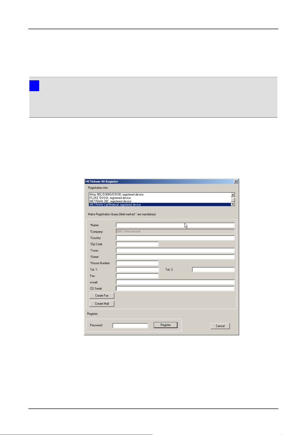
Opens the dialog box for entering the registration data:
►
►
along with your
The license key can be requested by fax or e
2 Installing, Registering and Uninstalling the Program
2.1 Installation
A Setup.exe file is included on the supplied CD ROM. The program is installed in dialog with the user by
executing this file. The installation directory and the program file folder can be selected as desired.
i
led to the same directory, as long as only the last digits of the
About in the Help menu.
2.2 Registration
The software can be tested for 30 days without a license key. In order to be able to use the software with its
full scope of functions after this trial period a license must be purchased, the software must be registered
with the licensor and it must be permanently enabled by entering the license key (password).
The assigned password depends on the entered company name and the type of calibrator. Registration must
thus be repeated for each type of calibrator.
gistration
Enter your address information to the corresponding fields. Be certain to enter
the company name correctly because the registration code is generated from it,
as well as other factors.
Enter the serial number which appears on the included program CD under “CD
Serial”. If you’ve received the software as a download or by e-mail and don’t
GOSSEN MET RA WATT 7
have a CD serial number, you’
registration (copy of the invoice or delivery note as a PDF or image file).
ll have to submit proof of purchase
-mail.
Page 8
►
►
►
⇒
bled
►
⇒
registration
Note 1
Registration is only possible for a single company, but for any desired nu
with a single software license (branch office license). Detailed information regarding licensing
can be viewed by clicking
Note 2
Save the returned e
METRAwin 90 - Operating Instructions
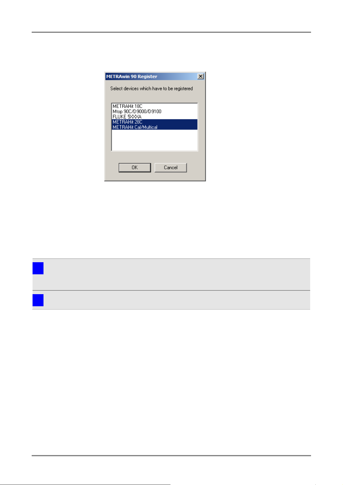
Click the corresponding button: [Create Fax] or [Create Mail].
Select the device type(s) for which the software will be registered in the dialog
box which then appears and acknowledge with [OK]. The selection option
depends on the purchased software variant.
Send the fax form or e-mail which then appears to the specified address.
You’ll receive the password with which the program can be permanently ena
for the specified device type(s) without delay.
Open the dialog box for entering the registration information once again to this
end, enter the password to the corresponding field and click the [Register]
button.
The program is then permanently enabled. You can check this in the
information field. Your company name is displayed in the title bar of the program
window after the program has been restarted.
i
mber of installations,
Show License Agreement in the Help menu.
i
-mail with the password in case reinstallation should become necessary!
2.3 Uninstalling the Software
If desired, the program can be uninstalled by selecting Programs from the Start menu and then clicking
Gossen-Metrawatt / METRAwin / Uninstall.
GOSSEN MET RA WATT 8
Page 9

METRAwin 90 - Operating Instructions
Starting the Program
In order to start the program:
►
or
►
⇒
Exiting the Program
In order to exit the program:
►
or
►
or
►
⇒
Note
When the program is exited the selected language and other software setting parameters
(device type, temperature unit of measure, communication parameters etc.) are saved
automatically. When the program is restarted, the last us
3 Operation
3.1 Starting and Exiting the Program
Double click the METRAwin 90 icon on the Windows desktop.
Select the program from the Windows start menu:
Start / Programs / METRAwin 90 / METRAwin 90
The program is started.
Select Close in the File menu.
Simultaneously press the Alt+F4 keys.
Click the Close icon at the upper right-hand corner of the title bar.
The program is exited.
i
ed settings are still valid.
GOSSEN MET RA WATT 9
Page 10

METRAwin 90 - Operating Instructions
The
Figure 3.2: Segments of the Program Window
A) Title Bar
The horizontal ba
registration information, as well as the file name of the currently open procedure. It
also includes the system menu at the left which can be opened via the
and buttons (
the program window
at the right.
B) Menu Bar
The menu bar includes the names of the main menus from which the various menu
functions and submenus can be accessed.
C) Toolbar
The smart icons in the toolbar allow for quick acces
and functions. The function of any given icon can be displayed by moving the mouse
pointer to it, and is executed by clicking the icon. After clicking
men
D) Command Line
Commands transmitted to the calibrator appear in this line for double checking. After
clicking
shown.
E) Control Bar
Program operating mo
procedures is made possible using the buttons in the control bar. The type
designation of the currently controlled calibrator is displayed at the far left, which has
been selected via the
F) Workspace
A calibrator control panel appears in this area in the DIRECT operating mode, or a
table is shown in the TEST operating mode which lists the parameters of the test
procedure steps. Various dialog boxes can be opened here
G) Context Menu
A context menu appears after clicking the right mouse button with the mouse pointer
in the workspace. Just like the toolbar, it allows for quick access to frequently
required functions.
B C D
A E F
G
3.2 Structure of the User Interface
METRAwin 90 program window is subdivided into seven segments:
r at the top of the program window shows the program name and
program icon,
) for minimizing, maximizing and closing
s to frequently used commands
Toolbar in the Setup
u, the toolbar can be hidden or shown.
Command Line in the Setup menu, the command line can be hidden or
des are selected, and sequential control of the test
Device Type setting in the Setup menu.
as well.
GOSSEN MET RA WATT 10
Page 11

METRAwin 90 - Operating Instructions
File Menu
New
Data associated with any previously loaded test calibration procedure are deleted after
Open
Opens a calibration procedure file with/without results (*.KLT/*.KLF) in the TEST
Save
Print test report
Prints out a standard calibration report with a predefined structure.
Printer settings
Selects and configures an installed printer for report printing.
Export test data
Exports the calibration data to an individually laid out Word/Excel report template
[Alt+F4]
Exit
Exit the Program
Edit Menu (only available in the TEST/PROCEDURE mode)
Undo
[Ctrl+X]
Cut
Cuts the selected TEST/PROCEDURE line.
Copy
Copies the selected TEST/PROCEDURE line to the clipboard.
[Ctrl+V]
Paste
Duplicate
Duplicates the selected TEST/PROCEDURE line.
Insert line
Adds a new TEST/PROCEDURE line after the selected line.
Insert procedure
Language
Changes the program menus, commands and descriptions to a different language.
Registration
Registers the software for permanent use via e-mail or fax.
Device type
Sets the program to work with another device type.
Port settings
Selects the port(s) for communication between the PC and the device and configure
Multimeter display on
Shows or hides the multimeter display.
Command line
Toolbar.
Shows or hides the toolbar.
Cold junction
°C/°F°K/
Selects the temperature unit of measure.
Help Menu
[F1]
Program functions
Opens a PDF file with a description of general program functions.
Device functions
Opens a PDF file with a description of device-specific program functions.
Online support
Opens a website with information regarding technical support via the Internet.
Show license agreement
Opens a TXT file with a description of the license agreement.
About
3.3 Overview of Menu Functions
[Ctrl+Z]
[CTRL+C]
confirming the security prompt.
operating mode.
Saves a calibration procedure file with/without results (*.KLT/*.KLF) in the TEST
operating mode.
(available after running the KLT2DOC.DOT or KLT2XLS.XLM macro).
Undoes the last editing step. The following can be undone: changes to the parameters
in a procedure line, cut and paste operations, the “Repeat” operation.
The TEST/PROCEDURE line which has been copied to the clipboard is inserted into
the selected line.
Setup Menu
the port parameters.
Shows or hides the command line.
Selects a thermocouple cold junction (internal/external) for the calibrator.
Displays information regarding program version and contact address.
GOSSEN MET RA WATT 11
Page 12

METRAwin 90 - Operating Instructions
File:
New
Deletion of the data associated with a calibration procedure in the TEST operating mode
All of the steps of any previously created or loaded test calibration procedure are
deleted after confirming the sec
File:
Open
Open a calibration procedure file with/without results in the TEST operating mode.
►
⇒
of the file to be opened. As a default function, the last saved or opened
Figure
Calibrating procedure filenames end with
(procedure template without results). Program files which can be loaded to the
METRAHit 18C calibrator
►
to which a connection has been
►
3.3.1 File Menu Functions
urity prompt.
A previously saved calibration procedure file can be selected and loaded to
temporary memory after clicking Open in the File menu while in the TEST
operating mode.
The Open dialog box which then appears prompts you to select or enter the
filename
file is suggested.
3.3.1-a: Dialog Box for Opening a Calibration Procedure File
.KLT (procedure with results) or .KLF
have a filename ending with .KLP.
GOSSEN MET RA WATT 12
Files located on local drives, or on network drives
established, can be opened. Select the directory path to the desired file in the
Look in dialog box.
By clicking a file in the file list, it’s selected as the measurement data file to be
opened. If a comment text was entered when the selected file was saved, the text
appears in the Comment field. Click [Open] in order to open the selected file.
Page 13

METRAwin 90 - Operating Instructions
►
•
•
•
Note 1
When a file is opened which contains data from a calibrator other the one currently selected
under
after acknowledgement of the prompt which appe ars in this c ase. If this progr a m vari ant is not
available, i.e. if the required device
enabled, the following message appears
Note 2
It
Note 3
Further Information regarding elements in this dialog box can be accessed via the direct help
function: First click
is required. A popup window with an appropriate explanation appears. This explanation can
also be display
help
File:
Save
After clicking
saved to a data storage medium so that they
Figure
Additional options can be selected via a further dialog box:
Test Header Only loads only the teat report header parameters of the selected
file for a previously opened/created calibration procedure.
Test Procedure loads the calibrating procedure only without results.
Test Procedure With Results loads the calibration proc edure al ong wit h the
included calibration results.
i
Device Type in t he Setup menu, the program switches to the current device type
i
’s not possible to open more than one calibration procedure file at a time.
i
in the menu which then appears.
-specific program module has not been instal led or
“Device is not installed - <device type designation>”.
? in the title bar of the window, and then click the element for which help
ed by clicking the element with the right mouse button and then clicking Direct
Save in the file menu, temporary procedure data are permanently
’re still available later on.
3.3.1-b: Dialog Box for Saving Procedure Files
GOSSEN MET RA WATT 13
Page 14

METRAwin 90 - Operating Instructions
⇒ You’re prompted to enter a filename in the Save as ... dialog box which then
►
►
been established. Select the desired directory path to which the file will be saved
►
►
Note 1
If the name of an already existing file is entered, a security prompt appears which asks t
user if he want
Note 2
Further Information regarding elements in this dialog box can be accessed via the direct help
function: First click
is required. A popup window with an appropriate explanation appears. This explanation can
also be display
help
File:
Print test report
Print out a standard calibration report with a predefined structure.
⇒
Figure
►
Enter information regarding the device to be calibrated (DUT) and the calibration
►
►
(*.KLT/*.KLF). Click the [Load] button to this end and selec t the file from which the
appears. The KLF file type is used for procedure files without results, and the
KLT file type for procedure files with results.
A text with up to 130 characters including 2 lines can be entered to the
Comment field as a description of the data included in the file. This comment
appears in the Open dialog box before a measurement data file is opened after
the file has been selected from the list.
Files can be saved to local drives, or to network drives to which a connection has
in the Save dialog box.
The file is saved to the selected directory using the desired filename by clicking
the [OK] button.
Saving the file can be aborted by clicking the [Cancel] button or b y pressing the
“ESC” key.
i
i
he
s to overwrite the respective file.
? in the title bar of the window, and then click the element for which help
ed by clicking the element with the right mouse button and then clicking Direct
in the context menu which then appears.
The Test Protocol Header dialog box appears first with numerous entry fields:
3.3.1-c: The Test Protocol Header Dialog Box
GOSSEN MET RA WATT 14
conditions to the entry fields in the left-hand column.
Information regarding the utilized calibration equipment can be entered to the
fields in the right-hand column.
Alternatively, these data can be read in from a previously saved test procedure file
Page 15

METRAwin 90 - Operating Instructions
test report header data will be loaded from the Open dialog box which the n a ppe a rs.
►
If the test procedure includes results in at least one line, the desired printer can
be selected and the standard calibration report can be printed out after clicking the
[Print]
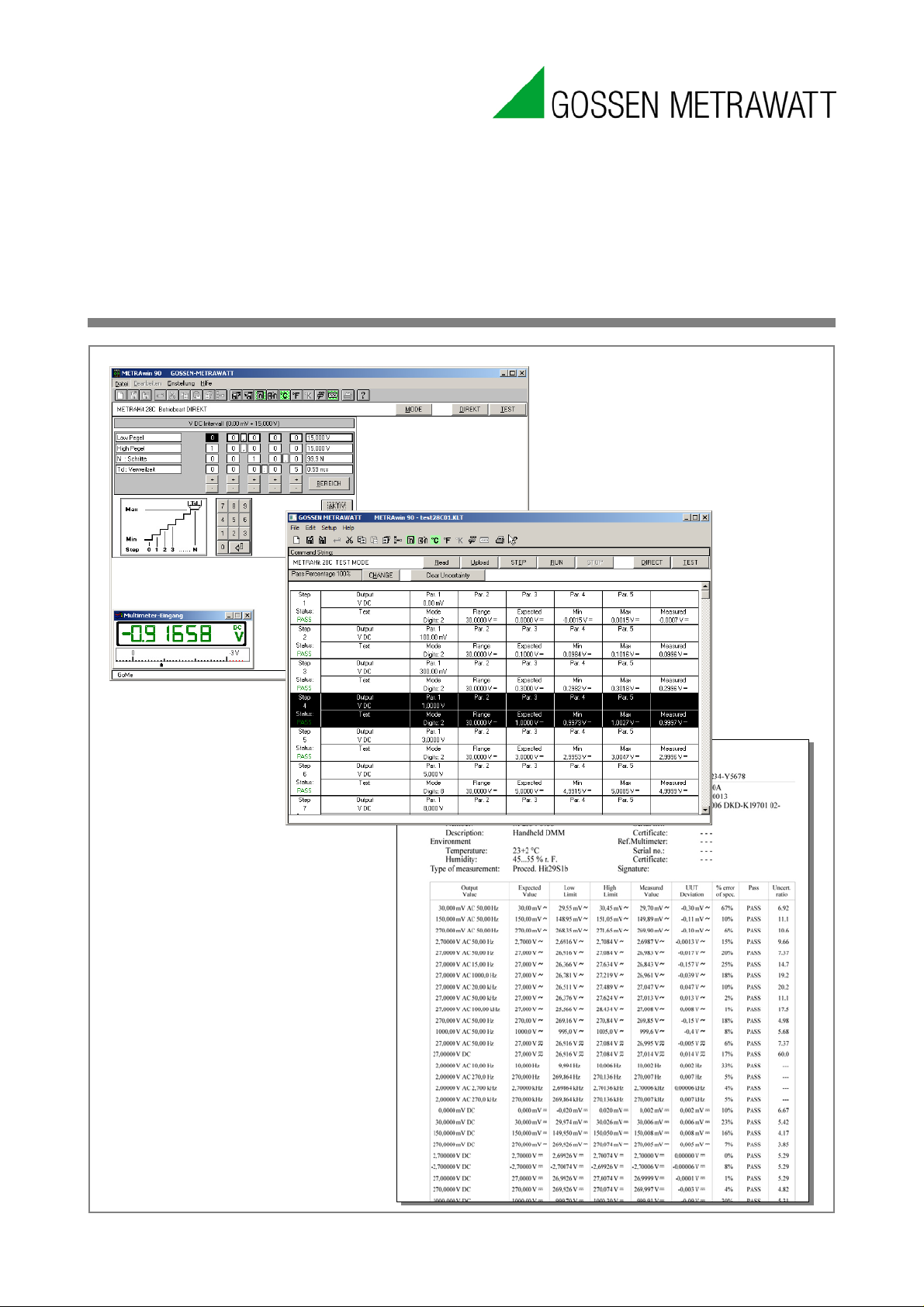
Figure 3.3.1-d: Example of a Standard Calibration Report
Alternatively, a calibration report with individualized layout and content can be
created with the help of the
File:
Printer settings
Select and configure an installed printer for report printing.
This command opens the standard Windows dialog box for printer configuration, in
which the printer to be used for printing out the calibration re
and configured.
File:
Export test data
Export the calibration data to an individually laid out Word/Excel report template
If the standard calibration report doesn
or if you want it to in
header data can be exported to an individually laid out Word or Excel report
The test procedure can be saved to the data storage medium with or without
results by clicking [Save] (see
button. This report is laid out as shown below:
Save in the File menu).
Export Test Data menu function.
clude, for example, a company logo, the calibration and report
’t contain the desired calibration parameters
GOSSEN MET RA WATT 15
port can be selected
.
Page 16

METRAwin 90 - Operating Instructions
template. Corresponding report templates with integrated macros can be found in
the program directory to this end.
Editing the Microsoft
►
and open the Word template with macro (KLT2DOC.DOT)
The included macro (AutoNew.MAIN) can import the following parameters from the
open test procedure with results
Report Header Parameter
Variable Name
Parameter
#lab
Issuing laboratory
#calby
Calibrated by
#caldate
Calibration date
#nextdate
Next calibration date (= calibration date + 12 months)
#uutmake
Manufacturer of the device under test
#uuttype
Type designation of the device under test
#uutnumb
Serial number of the device under test
#uutdsc
Object (type of device under test)
#envtemp
Ambient temperature
#envhmdt
Relative humidity
#meatype
Type of measurement
#certnum
Certificate number
#caldev
Type designation of the calibrator
#calno
Serial number of the calibrator
#calcert
Calibrator certificate number
#muldev
Type designation of the multimeter
#mulno
Serial number of the multimeter
#mulcert
Multimeter certificate number
#refdev
Type designation of the reference multimeter
#refno
Serial number of the reference multimeter
#refcert
Reference multimeter certificate number
Procedure Step Parameter
Variable Name
Parameter
#fun
(Measuring) function (“V DC”, “RTD” ...)
#mrange
Measuring range (“3.0000 V DC”)
#tpoint
Test point
#outval
Output value and unit of measure (“2.50000 V DC”, “100 °C Pt100” …)
#param
Additional parameter (“1.00 kHz” for V AC, “Pt100” for temperature)
#adig
Permissible deviation in digits
#expval
Expected value
#fexpval
Expected value with measuring function (ACDC)
#minval
Lower limit value
#fminval
Lower limit value with measuring function
®
Start Micros of t® Word
located in the program directory.
Word report template included with the program
based on the variable names:
s
#maxval Upper limit value
#fmaxval Upper limit value with measuring function
GOSSEN MET RA WATT 16
s
Page 17

METRAwin 90 - Operating Instructions
#rprc
Measured difference as percentage of the specification
#result
Assessment: pass/limit/fail/---
#text
Comment regarding the test step
#udig
Measuring uncertainty in digits
#uval
Measuring uncertainty (absolute value)
#urat
Measuring uncertainty ratio
General Parameters
Variable Name
Parameter
#passprc
Pass percentage for limit value
#measured
Number of measured steps
#passed
Number of passed steps
#limit
Number of limit steps (between limit value and failure)
#fail
Number of failed steps
►
in accordance with your needs and save the
Running the Word macro and transferring the calibration data t
►
►
⇒
⇒
⇒
⇒
The data are transferred to the Word file and completion is acknowledged with a
Calibration data can be transferred to Excel in a similar way. However, the macro and
the report templates are located in separate files in the p
►
⇒
►
#regval Measured value
#fregval Measured value with measuring function
#rdev Measured difference (absolute value)
#frdev Measured difference with measuring function
#rdig Measured difference in digits
Adapt structure and column content
edited file as a Word 97 or 2003 template (*.DOT), or as Word template with
macros (*.DOTM) with a new name.
Start Micros of t® Word and open the desired Word template with macro.
Start the included AutoNew.MAIN macro by clicking Macros and then View
Macros in the View menu.
Respond to the prompt asking whether or not you want to receive data from the
calibration program with [Yes]:
In the window which then appears, you’re prompted to open a test procedure
file. If this file has already been opened, click [Cancel].
Now you ’re prompted to start calibration (if you haven’t already done so) and
then to select the export test data menu command.
ready message.
o the Word report template
Start Micros of t® Excel and open the KLT2DOC.XLM Excel macro file.
Two icons now appear underneath the add-ins with the designations KLT:Get
calibrator data and KLT:Close.
Click the KLT:Get calibrator data icon and select the report template file
(KLT2XLSx.XLT) to be opened in the window which then appears.
GOSSEN MET RA WATT 17
rogram directory in this case.
Page 18

METRAwin 90 - Operating Instructions
Program Functions
Opens a PDF file with a description of general program functions.
This menu command starts Adobe
file
Device Functions
Opens a PDF file with a description of device-specific program functions.
This menu command starts Adobe
document which includes des c riptio
characteristics with reference to the measuring instrument which is currently
selected under
Online Support
Opens a website with information regarding technical support via the Internet.
This menu command starts your Inter net bro wser and opens a webs ite wit h
information on how our technical support team can provide you with support via the
Internet.
Display License
A
Opens a TXT file with a description of the license agreement.
Th
new window.
Info
Displays information regarding program version and contact address.
This menu command opens a window which displays information regarding the
revision level o
technical support.
When the program is started for the first time, the language which was selected
during installation is use
selecting
with the last selected language.
Select the type of calibrator t
The various calibrators which are available for selection depend on which version of
the program you purchased and which device(s) your chose during installation.
An image of the selected calibrator appe
after
with specific connection and operating instructions can be opened by clicking Device
Functions
3.3.2 Help Menu
which includes descriptions of general program functions.
®
Reader™ in a new window, and opens a PDF
®
Reader™ in a new window and opens a PDF
ns of specific program functions and
Device Type in the Setup menu.
greement
is menu command starts your text editor and displays the license agreement in a
f the utilized program version, as well as the contact address for
3.4 Basic Program Settings
3.4.1 Changing the User Interface Language
d for the user interface. This language can be changed by
English / Deutsch / ... in the Setup menu. The program always starts up
3.4.2 Selecting the Type of Calibrator to be Controlled
o be controlled under Device Type in the Setup menu.
the device type has been changed. Depending on the device type, a PDF file
ars as an initial window in the workspace
in the Help menu.
METRAHit 18C METRAHit 28C/28C light METRAHit Cal/Multical
GOSSEN MET RA WATT 18
Page 19

METRAwin 90 - Operating Instructions
The corresponding dialog box appears after clicking
Its content depends on which
Device
can be accessed after clicking
Figure
Figure
USB X
METRAtop 90C/D9000/D9100 FLUKE 5100A/5500A/5520A/5700A
3.4.3 Port Settings
type of calibrator is currently selected to be controlled.
-specific port settings are described in a separate document. This document
Device Functions in the Help menu.
a) For METRAtop 90C / FLUKE D9000, D9100, 5100A, 5500A, 5520A and 5700A multifunction calibrators
Port Setup in the Setup menu.
3.4.3-a: Port Settings for FLUKE 5XXXA with METRAHit 1XS and SI232 Adapter
b) For METRAHit CAL and METRACAL MC process calibrators
3.4.3-b: Port Settings for METRAHIT CAL and USB X-TRA with METRAHit X-TRA and
-TRA
GOSSEN MET RA WATT 19
Page 20

METRAwin 90 - Operating Instructions
Figure
Figure
c) For METRAHit 28C and 28C light process calibrators
3.4.3-c: Port Settings for METRAHIT 28C and BD232 with METRAHit 28S and BD232
d) For METRAHit 18C process calibrator
3.4.3-d: Port Settings for METRAHit 18C and BD232 with METRAHit 18S SI232
GOSSEN MET RA WATT 20
Page 21

METRAwin 90 - Operating Instructions
After clicking
menu, a window can be viewed in
the workspace in which the current measured values of the connected multimeter
are display
continuously look back and forth between the monitor screen and the multimeter.
After clicking the minimize icon
display of the measured value is hidden and the meas
numeric
Figure
Figure
Multimeter and an Additional Reference Multimeter
The command line can be shown or hidden with the help of the
function in the
Commands transmitted to the calibrator appear in thi
The toolbar can be shown or hidden with the help of the
Setup
The toolbar contains buttons which can be used to quickly execute commands
without accessing the menu
form of so
Note
Just like the tool bar, the
functions.
You can specify whethe
temperature measurement and simulation after clicking
menu.
Note 1
Only
calibrator.
3.4.4 Showing and Hiding the Multimeter Display
3.4.4-a: Multimeter Display in Normal and Minimized Format
Multimeter Display On in the Setup
ed in analog and digital format. This makes it unnecessary to
in the multimeter input window, the graphic
ured value appears as a
value.
3.4.4-b: Multimeter Displays of the Calibrator-
3.4.5 Showing and Hiding the Command Line
Setup menu.
3.4.6 Showing and Hiding the Toolbar
menu.
s. The functions assigned to the buttons appear in the
-called “quick-info” when the mouse is positioned at the respective button.
i
3.4.7 Specifying the Temperature Unit of Measure
context menu also permits quick access to frequently required
r degrees Celsius, Fahrenheit or Kelvin will be used for
Command Line
s line for double checking.
Toolbar function in the
°C / °F / °K in the Setup
i
GOSSEN MET RA WATT 21
those units of measure are available which are supported by the currently utilized
Page 22

METRAwin 90 - Operating Instructions
Note 2
Temperature is generally saved in °C in the test procedures.
The
to specify whether the
externally
simulation with the calibrator.
If
used to manually enter the measured cold junction temperature (the temperature at
the connection for the simulated thermocouple sensor). If the METRAHit multimeter
with temperature sensor c
measurement, the temperature can be read in online by clicking the
multimeter
activated, the temperature is continuously monitored by the multimeter, forwarded to
the calibrator via the port and taken into account by the calibrator.
Figure
i
3.4.8 Specifying the Thermocouple Cold Junction
Internal/External Cold Junction function in the Setup menu makes it possible
internally measured temperature inside the calibrator or the
measured temperature will be used as the cold junction for thermocouple
external cold junction temperature is selected, a dialog box appears which can be
onnected to the PC is used for this temperature
“Get from
” button. If the “Link Calibrator with Multimeter” checkbox has been
3.4.8-a: Dialog Box for Setting the External Cold Junction Temperature
GOSSEN MET RA WATT 22
Page 23

METRAwin 90 - Operating Instructions
3.5
In this operating mode, the calibrator is interactively controlled by the PC via the
selected port. This is especially helpful during adjustment and balancing of
amplifiers, measuring transducers, analog components
►
►
►
⇒
►
►
The entry of erroneous calibration values is prevented.
The multimeter’s display value can be viewed at the monitor screen at the same time
by clicking
DIRECT Operating Mode for Interactive Calibrator Operation
Click the [DIRECT] button in the control bar.
Then click the [MODE] button in the control bar in order to select the desired
simulation function at the calibrator:
Select the desired output function and operating mode and acknowledge by
clicking the [OK] button.
A control panel for configuring the parameters of the selected function then
appears in the workspace:
and multimeters.
Select the parameters to be configured and enter the setpoint value either
numerically or by adjusting the displayed value at the corresponding decimal
place with the [+] and [-] keys.
After clicking [ACTIVE], the parameter values are transmitted to the calibrator
which is then correspondingly configured. If the active state has already been
initialized, the changes are implemented immediately.
GOSSEN MET RA WATT 23
Multimeter Display On in the Setup menu.
Page 24

METRAwin 90 - Operating Instructions
3.6 TEST Operating Mo de
3.6.1
►
⇒
►
►
⇒
►
⇒
Test Parameters
Creating a Calibration Procedur e
Click the [TEST] button in the control bar.
The first procedure line appears in the workspace which consists of an upper
“output line” for programming the calibration signal and a lower “input line” for
the expected results at the device to be calibrated and the allowable tolerances.
Double click into the procedure line’s Step field in order to select the desired
simulation function at the calibrator.
Select the desired output function and operating mode, and acknowledge by
clicking the [OK] button.
A control panel for configuring the parameters of the selected function then
appears in the workspace:
Select the parameters to be configured and enter the setpoint value either
numerically or by adjusting the displayed value at the corresponding decimal
place with the [+] and [-] keys. Acknowledge your entry with [OK].
The
GOSSEN MET RA WATT 24
dialog box appears.
Page 25

METRAwin 90 - Operating Instructions
►
read in from the multimeter via the PC’s serial port with
After this step has been completed, the next procedure line appears automatically
which is filled out in the same way using the mou
standard Windows tools (copy and paste, or repeat with subsequent modification).
This process is repeated
completed. Suggestions regarding tolerance specifica
step appear automatically in the next step.
Enter or select:
• How the measured value will be entered to the program:
Multimeter Input
The measured value is
the help of an adapter.
Manual Input
The displayed actual value for the device to be calibrated is read and entered
using the PC’s keyboard.
Variable Output
The calibration signal is continuously changed at the monitor or the calibrator
by means of manual tracking with a decade device until the display at the
measuring or recording instrument coincides with the specified setpoint.
• When the measured value read in via the port is valid (Wait)
• Which measured value is expected from the device under test (UUT
Expected Value) and how accurate the value should be (UUT Specification)
• Whether or not an auto-message will app ear at the monitor screen
• Whether or not an individual message will be read out to the user before
executing a procedure step
se, or is created with the help of
for all of the calibration points until the procedure has been
GOSSEN MET RA WATT 25
tions in any given procedure
Page 26

METRAwin 90 - Operating Instructions
►
3.6.2 Executing a Calibration Procedure
Click the [RUN] button in the control bar if you want to execute the procedure
beginning with the selected step, or click the [STEP] button if you only want to
execute the selected step.
Edited in Germany • Subject to change without notice • A PDF version available on the Internet
Phone: +49 911 8602-111
GMC-I Messtechnik GmbH Fax: +49 911 8602-777
Südwestpark 15 e-mail info@gossenmetrawatt.com
90449 Nürnberg • Germany www.gossenmetrawatt.com
 Loading...