

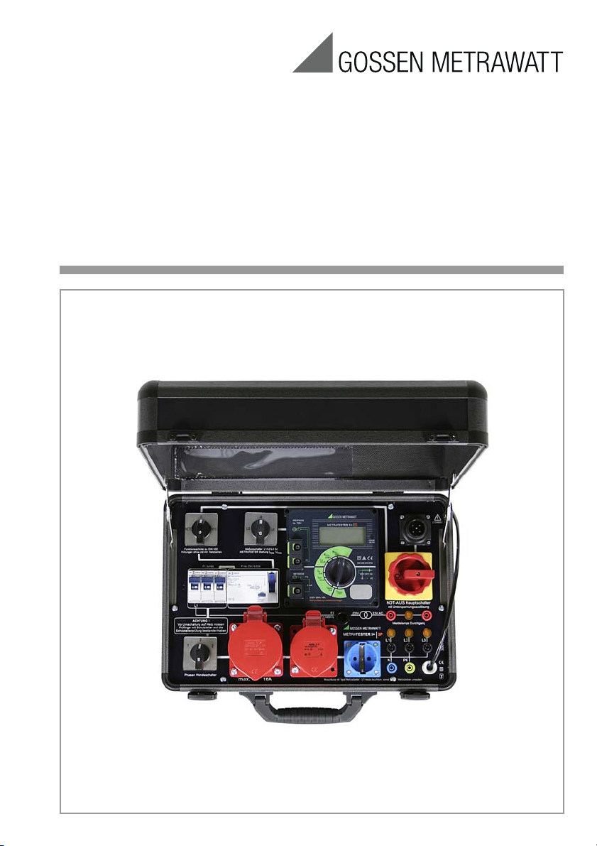
Operating Instructions
METRATESTER 5+3P
Workshop Test Panel for Testing Devices
per DIN VDE 0701-0702 and DIN VDE 0104
3-349-414-03
7/5.13
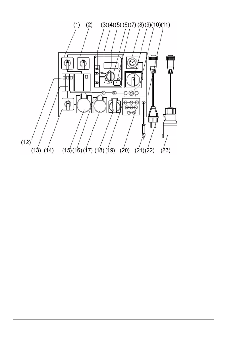
1 NETZ-VDE switch (mains-VDE)
2 Measuring selector switch: L1-L2-L3
3 Connector socket/terminal for DUT
phase conductor (parallel to test sockets)
4 Connector socket/terminal for DUT pro-
tective conductor (parallel to test sockets)
5 Connector socket/terminal for
conductive parts of the DUT for testing
for the absence of voltage in accordance
with DIN VDE 0701–0702, and for
contact current measurement for
protection class II devices
6 Measuring function selector switch for
METRATESTER 5+
7 Contact surface for finger contact
8 Plug connector for mains cables
9 Mains / emergency stop switch,
12 RCD (residual current circuit beaker)
4*25 A, 0.03 A
13 Three circuit breakers, B16 A
14 Polarity reversing switch
15 CEE socket, 3P+N+PE, 32 A, 230/400 V
max. 16 A !
16 Fuse, T 0.1/250G
17 CEE socket, 3P+N+PE, 16 A, 230/400 V
18 Earthing contact outlet
19 Mains indicator lamps, L1-L2-L3
20 Test sockets, L1-L2-L3-N-PE
21 Probe cable with clip / test probe
22 Mains cable with earthing contact plug
and coupling socket
23 Mains cable with CEE 16 A, 5-pole
mains plug and coupling socket
undervoltage trigger can be locked at
zero setting
10 “Durchgang” (continuity) indicator lamp
11 Connector sockets for continuity test
with max. 33 V AC
2 GMC-I Messtechnik GmbH

Table of Contents Page
1 Applications ....................................................................................................................4
2 Safety Precautions .........................................................................................................4
3 Standard Equipment and Accessories ............................................................................6
4
Connecting the Test Case to the Mains and Testing the Mains Connection ..........................6
4.1 Connecting the Test Case ................................................................................................................. 6
4.2 Testing Protective Conductor Potential ............................................................................................... 6
4.3 Measuring Line Voltage .................................................................................................................... 7
5 Connecting the DUT to the Test Case ............................................................................. 8
5.1 Protection Class I Devices ................................................................................................................. 8
5.2 Protection Class II and III Devices ...................................................................................................... 9
5.3 Devices with Single or Multi-Phase Connection without Plug ............................................................... 9
5.4 Stationary Devices for Protective Conductor Testing via the Supply Mains .......................................... 10
5.5 Data Processing Equipment ............................................................................................................ 10
5.6 Extension Cables with the VL2 E Accessory ..................................................................................... 11
5.7 Setting the Switches at the Test Case .............................................................................................. 11
5.8 Setting the Switches at the Device Under Test ................................................................................. 11
6 Testing Devices in Accordance with DIN VDE 0701-0702 ............................................12
6.1 Measuring Protective Conductor Resistance for Protection Class I Devices ......................................... 12
6.2 Measuring Insulation Resistance ..................................................................................................... 13
6.3 Measuring Protective Conductor Resistance ..................................................................................... 15
6.3.1 Equivalent Leakage Current ............................................................................................................ 15
6.3.2 Differential Current Measurement for Protection Class I Devices ........................................................ 16
6.4 Measuring Contact Current ............................................................................................................. 17
6.4.1 Contact Current Measurement – Differential Current ........................................................................17
6.4.2 Testing in Accordance with the Direct Method ................................................................................. 17
6.5 Measuring Load Current and Voltage at the Consumer ..................................................................... 18
7 Testing Extension Cables with the VL2 E Accessory ....................................................19
7.1 DIN VDE Tests for Extension Cables ................................................................................................. 19
7.2 Function Test for Extension Cables .................................................................................................. 19
8 Continuity Test with Extra-Low Voltage ........................................................................ 20
9 Display and Indicators at the Test Instruments ............................................................20
9.1 Indication of Errors and Limit Values ................................................................................................ 20
10 Technical Data ..............................................................................................................21
10.1 Test case ...................................................................................................................................... 21
10.2 METRATESTER 5 + Test Instrument ................................................................................................. 22
11 Maintenance – Recalibration ........................................................................................ 25
11.1 Housing Maintenance ..................................................................................................................... 25
11.2 Recalibration .................................................................................................................................. 25
11.3 Periodic Self-Test of the Connector Cable for Protective Conductor Continuity .................................... 26
11.4 Testing the Integrated RCD (residual current circuit breaker) ............................................................. 26
GMC-I Messtechnik GmbH 3

11.5 Fuse Replacement .......................................................................................................................... 26
11.6 Return and Environmentally Sound Disposal ..................................................................................... 26
12 Repair and Replacement Parts Service
Calibration Center * and Rental Instrument Service .....................................................27
13 Product Support ............................................................................................................28
1 Applications
The portable test case, manufactured in accordance with “guidelines for equipment required
for electrical installation operations”, is intended for use by qualified electricians for
measuring and testing electrical devices after repair or modifications, as well as for periodic
testing, in accordance with DIN VDE 0701-0702.
According to these regulations, protective conductor resistance, insulation resistance,
differential current, contact current and equivalent leakage current must be measured, and
testing for the absence of voltage must be executed at user accessible conductive parts at
data processing equipment and office machines.
Further applications for the substantiation of correct functioning of electrical equipment
include the measurement of operating voltage and current consumption at devices under
test. Beyond this, the protective conductor at the mains connection can be tested for the
absence of voltage and line voltage can be measured. Extension cables can be tested after
connecting the VL2 E accessory.
2 Safety Precautions
The test case is equipped with a METRATESTER 5+ test instrument, and has been
manufactured and tested in accordance with the following regulations:
IEC 61010-1,
DIN EN 61010-1,
VDE 0411-1 “Regulations for electronic testers and controllers,
Part 1: safety measures for electronic measuring instruments”
and DIN VDE 0404 “Devices for technical safety testing of electrical equipment, part 1:
General requirements,
and part 2: Devices for periodic testing”
If used for its intended purpose, safety of the test case and of the user is assured. Their
safety is however not guaranteed, if the test case is used improperly or handled carelessly.
In order to maintain flawless technical safety conditions, and to assure safe use, it is
imperative that you read these operating instructions thoroughly and carefully before placing
the test case into service, and that you follow all instructions contained herein.
4 GMC-I Messtechnik GmbH
Observe the following safety precautions:
Attention!
!
• Measurements within electrical systems are prohibited!
• The test case may only be connected to 230/400 V mains system with 50 Hz and a 16 A
fuse via the 5-pole (23) or 3-pole (22) mains cable.
• In order to avoid undesired shutdown in the event of a defective device under test, the
mains outlets should be separately fused if at all possible!
A defect in the DUT may trip the mains power RCD (residual current circuit breaker), and
thus cause a service interruption. If DUTs are being tested which cannot be
disconnected from the mains intermittently, an RCD (residual current circuit breaker) can
also trip the power supply circuit (test per section 6.4.1).
The manufacturer of the test case assumes no liability for loss of data or other damage
which results from its use.
• Be prepared for the occurrence of unexpected voltages at devices under test. For
example, capacitors may be dangerously charged.
• If the test case is connected via the earthing contact mains adapter, phase conductor L1
may be connected to the N safety socket if poled accordingly! If this is the case, reverse
polarity of the plug at the mains adapter (see section 4.1).
• Before connecting the device under test to the test case, subject it to a thorough visual
inspection first. Devices under test with visibly damaged insulation must be repaired
before metrological testing is performed.
• If the test case and/or its connector cables demonstrate visible damage, no longer
function, have been stored for a lengthy period of time under unfavorable conditions or
have been subjected to excessive stress during transport, it must be assumed that
hazard-free operation is no longer possible. If this is the case, remove the test case from
service and secure it against inadvertent use, for example by locking it up.
The NETZ-VDE switch (2) may only be set to the “NETZ” (mains) position after devices
under test with a protective conductor have passed the protective conductor test.
For reasons of safety, the device under test must be turned off before switching to “Netz”
(mains), so that dangerous devices under test (e.g. a circular saw) can only be switched on
intentionally.
• Due to the fact that the test case is laid out in accordance with DIN VDE 0404, the “PE”
safety socket and the “PE” contacts in the outlet may only be connected to the mains
protective conductor after the NETZ-VDE switch has been set to the “Netz” (mains)
position.
• In order to assure compliance with technical safety requirements, the test case may only
be repaired by a qualified electrician, who is preferably employed by the manufacturer.
• Before opening the test case in order to carry out repairs, it must be disconnected from
the mains by pulling the plug from the electrical outlet.
• Disconnect the test case from the mains whenever work is interrupted and secure it
against unauthorized use, for example by locking the cover.
• Use recommended accessories only!
GMC-I Messtechnik GmbH 5

Meaning of Symbols on the Instrument
!
Warning concerning a source of danger
(attention: observe documentation!)
EC label of conformity
This device may not be disposed of with the trash. Further information regarding
the WEEE mark can be accessed on the Internet at www.gossenmetrawatt.com
by entering the search term WEEE.
3 Standard Equipment and Accessories
Scope of Delivery
1 test case
2 mains cables (Schuko and CEE16A)
1 measurement cable with test probe, 1 alligator clip
1 set of operating instructions
Accessories
SECU-cal 10 calibration adapter (M662A)
VL2 E test adapter for testing cables (Z745W)
4 Connecting the Test Case to the Mains and Testing the Mains Connection
4.1 Connecting the Test Case
Set the switches as follows before connecting to the mains:
Set the NETZ–VDE switch (1) to “NETZ”, set the METRATESTER 5 + measuring function
selector switch (6) to “250 V”, set the polarity reversing switch (14) to “1”, set the L1-L2-L3
measuring selector switch (2) to “L1” and then connect the test case to the mains. Set the
mains switch (9) and the RCD (residual current circuit breaker) (12) to “EIN” (on). According
to the manufacturer, the emergency stop switch may generate minor humming noises with
the U coil in certain armature positions. If this is the case, quickly turn the emergency stop
switch on and off several times.
When connected via the 5-pole CEE mains adapter (23), indicator lamps L1, L2 and L3 (19)
must light up, and when connected via the earthing contact mains adapter (22), only
indicator lamp L1 should light up. Mains polarity is tested for this type of connection, i.e. if
lamp L1 does not light up, the polarity of the earthing contact plug must be reversed in the
mains outlet.
If this is not the case, immediately disconnect the test case from the mains.
The fault at the mains connection or the test case must be eliminated before executing any
tests.
4.2 Testing Protective Conductor Potential
Touch the contact surface (7) with your finger, and touch a grounded object at the same time
(e.g. a water pipe). The PE indicator lamp may not light up! If this is the case, potential between
the protective conductor at the mains plug (22/23) and the contact surface (7) is 100 V.
6 GMC-I Messtechnik GmbH

When connected via the 5-pole CEE mains plug (23), indicator lamps L1, L2 and L3 (19)
Note!
Attention!
!
Note!
must light up. When connected via the earthing contact mains adapter (22), only indicator
lamp L1 should light up. Mains polarity is tested for this type of connection, i.e. if lamp L1 does
not light up, the polarity of the earthing contact plug must be reversed in the mains outlet. If this is not
the case, immediately disconnect the test case from the mains. The fault at the mains connection
or the test case must be eliminated before executing any further tests.
If the PE signal lamp lights up when you touch the contact surface (7), potential between the
protective conductor at the mains plug (22/23) and the contact surface (7) is 25 V, i.e. the
protective conductor is conducting voltage.
Depending upon handling, potential transfer may occur which causes the PE signal
lamp to light up. For example, this could be the case if you touch a device under test
with the NETZ-VDE switch (1) in the “VDE” position, thus creating a capacitive voltage
divider.
If, while testing protective conductor potential, you determine that the mains
protective conductor is conducting voltage, no measurements may be performed
with the test case. If this is the case, potentially dangerous voltage is also present at
the user accessible earthing contacts at the outlets, the “PE” socket (20) and the jack
(4). Immediately disconnect the test case from the mains and arrange to have the
fault eliminated at the mains connection. Voltage in the mains protective conductor
also results in incorrect measured values when testing for the absence of voltage in
accordance with DIN VDE 0701-0702 (see section 6.4.1).
4.3 Measuring Line Voltage
• Set the measuring function selector switch (6) to “250 V~”.
• If connected via the 5-pole CEE mains adapter, set the measuring selector switch (2) to
the L1, L2 and L3 settings, one after the other, and if connected via the earthing contact
mains adapter set the switch to L1 and read the measured value from the LCD panel for
each switch setting.
Line voltage must always lie within the permissible range of 207 to 253 V.
If line voltage is present, values are displayed at the with the measuring function
selector switch (6) in each of its respective positions, even if no device under test has
been connected.
The display of such numbers indicates that line voltage is present, regardless of the
position to which the measuring function selector switch (6) has been set. If the
selector switch has been set to “250 V~”, these numbers represent the actual line
voltage value. In all other detented switch positions – if no device under test has been
connected – these numbers do not represent actual measured values.
If the test case has been connected via the earthing contact mains adapter, all tests and
measurements can be performed except tests at 3-phase current devices under mains
operating conditions.
GMC-I Messtechnik GmbH 7
5 Connecting the DUT to the Test Case
Mains Connection Sockets
Switch the DUT on!
Either
Depending upon its plug, connect the DUT to one of the outlets, or to the connector sockets
in the case of loose wire ends.
It is absolutely mandatory to execute the tests in the order in which they are specified here!
1 Visual inspection
2 Measurement of protective conductor resistance for protection class I devices
3 Measurement of insulation characteristics if technically feasible, i.e. if the DUT does not
include any electrically actuated, all-pole switches:
– Insulation resistance followed by protective conductor or equivalent leakage current
– Otherwise: leakage current during operation, differential current, protection class I
devices
Contact current for protection class II devices
Safety extra-low voltage (only at point of connection of safety extra-low voltage
generated in the DUT)
4 Function Test
5 Labeling inspection
6 Documentation
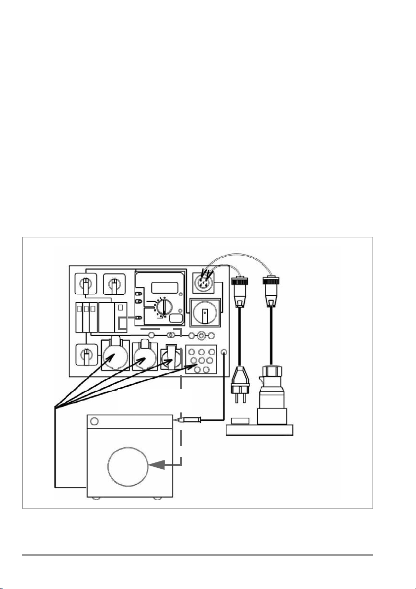
5.1 Protection Class I Devices
8 GMC-I Messtechnik GmbH
5.2 Protection Class II and III Devices
Connect the DUT, for example to the
earthing contact outlet, or to the connector sockets in the case of loose wire ends.
Switch the DUT on!
Mains Connection Sockets
To Accessible
Metal Parts
Either
Mains Connection Sockets
Switch the DUT on!
Either
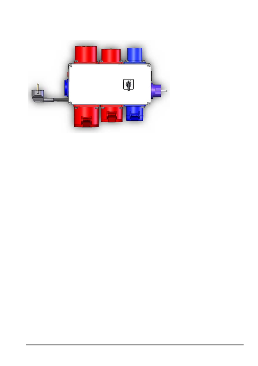
5.3 Devices with Single or Multi-Phase Connection without Plug
GMC-I Messtechnik GmbH 9

5.4 Stationary Devices for Protective Conductor Testing via the Supply Mains
Either
Mains Connection Sockets
Switch the DUT on!
To M ai n s
Protective Conductor
Mains Connection Sockets
Switch the DUT on!
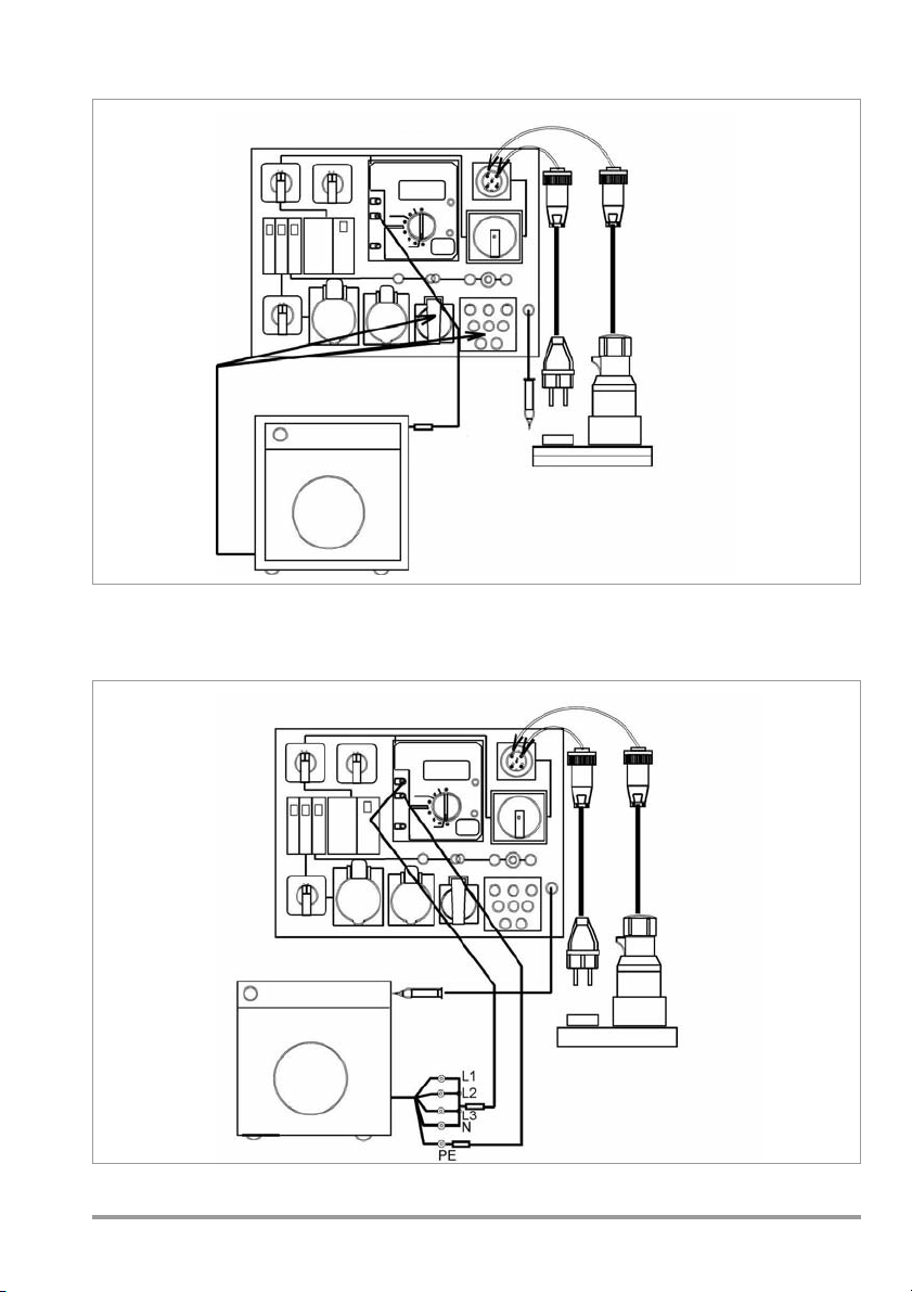
5.5 Data Processing Equipment
Either
10 GMC-I Messtechnik GmbH

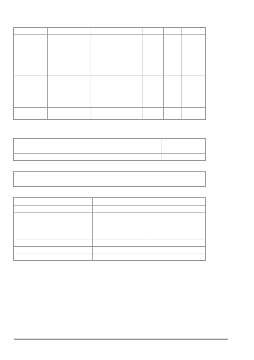
5.6 Extension Cables with the VL2 E Accessory
Either
Mains Connection Sockets
VL2 E Test Adapter
5.7 Setting the Switches at the Test Case
The following settings must be made after visual inspection has been passed, and before the
DUT is connected to the corresponding plug connectors at the test case, as well as before
each new test:
NETZ–VDE switch (1) Set to “VDE”
METRATESTER 5 + function selector switch (6) Set to “I
Polarity reversing switch (14) Set to “1”
Measuring selector switch L1-L2-L3 (2) Set to “L1”
20 mA”
EA
5.8 Setting the Switches at the Device Under Test
Connect the device under test to the test case and switch all of its functions on, making sure
that, for example, thermostat contacts are closed etc.
GMC-I Messtechnik GmbH 11

6 Testing Devices in Accordance with DIN VDE 0701-0702
Note!
Note!
Always measure protective conductor resistance first for safety class I devices under test.
Measurement of insulation resistance, equivalent leakage current and protective conductor
current is not possible without a properly functioning protective conductor. This
measurement is of special importance because a defective or reversed protective conductor
may represent a hazard for the user!
Please note that the display indicates overloading when measuring protective
conductor resistance and insulation resistance, if the terminals are open or if the
upper range limit is exceeded. Only “O.L” appears at the display in this case.
The limit values specified in the following sections correspond to the current status at
the time or printing. Please note that normative legislation is continuously updated to
meet the safety requirements necessitated by changing market situations, and that
the listed limit values are thus subject to change.
6.1 Measuring Protective Conductor Resistance for Protection Class I Devices
Connect the single-pole probe cable with test probe and clip (21) to the housing of the DUT
in accordance with section 5.1. Assure good contact. In the case of stationary DUTs,
measurement can be performed without interrupting the mains connection. To this end,
connection must first be established from the protective conductor socket (4) at the METRATESTER 5+ to a protective conductor which has been previously tested for the absence of
voltage – for example at an outlet within the electrical system – which is
connected with the protective conductor of the DUT. When testing in accordance with
DIN VDE 0701-0702, DUTs with external connections such as data cables etc. can be
tested within their entire configuration at the installation site (see section 5.4 regarding
connection).
However, due to the fact that this test does not provide any indication as to the safety of the
device under test, complete testing via the connector sockets at the test case must be
performed as soon as disconnection from the mains and the connector cables is possible –
insofar as permitted by the device.
Ð Set the measuring function selector switch (6) to the “20 Ohm” range.
Ð Read the measured value in Ohms at from the LCD panel, and compare it to permissible
values in accordance with DIN VDE 0701-0702.
Protective conductor resistance may not exceed the following resistance values:
Maximum Permissible Values for Protective Conductor Resistance Relative to Cable Length
(per DIN VDE 0701-0702:2008)
Lengths up to [m] 5 12.5 20 27.5 35 42.5 50 More than 50
Max. resistance [] 0.3 0.4 0.5 0.6 0.7 0.8 0.9 1.0
A value of 1 may not be exceeded on any case. The table applies to cable reels and extension cables
as well.
In the case of longer cables, 0.1 Ohms is added per additional 7.5 m cable length regardless
of conductor cross-section.
12 GMC-I Messtechnik GmbH

Attention!
!
The connector cable must be shaken back and forth, section by section over its
Attention!
!
Attention!
!
entire length, during measurement (for permanently installed devices only insofar as
the connector cable is accessible during repair, modification or testing).
Unrealistic, continuously changing measured values indicate poor contact, a damaged
protective conductor or a broken core in the probe cable (21) in the event that it has been
excessively stressed! If brief or continuous interruption of the protective conductor occurs
during the manual step of the continuity test, the limit value indicator at the
METRATESTER 5 + test instrument lights up and an acoustic warning signal is generated. In
such cases, the interruption must be repaired in a professional manner and measurement
must be repeated.
Measurement of protective conductor resistance is of course impossible for devices which
are not equipped with a protective conductor (e.g. protection class II and III devices).
6.2 Measuring Insulation Resistance
This test must be performed on all DUTs for which all insulation is checked during testing
without applying mains voltage (practically all DUTs without electrically actuated switches
and relays). If this is only possible after applying mains voltage, testing in accordance with
section 6.3.2/section 6.4.1 must be performed. If there is any doubt about performing
measurement with insulation voltage, for example at electronic devices, measurement must
also be performed in accordance with section 6.3.2/section 6.4.1.
It must be assured that all switches, thermostats etc. are closed!
Do not touch the instrument’s terminal contacts during insulation resistance
measurements!
If nothing has been connected to the terminal contacts, or if a resistive load component has
been connected for measurement, your body would be exposed to a current of approx.
1 mA at a voltage of 500 V. The resulting electrical shock is not life endangering. However,
the noticeable shock may lead to injury (e.g. resulting from a startled reaction etc.).
If measurement is performed at a capacitive object such as a long cable, it becomes
charged with up to approx. 500 V! Touching such objects is life endangering!
In accordance with DIN VDE 0701-0702, L1, L2, L3 and N (short-circuited) are measured
against PE during this test (connection per section 5.2).
Ð Switch the DUT on in all functions.
Ð Set the NETZ-VDE switch to “VDE”.
Ð Set the measuring function selector switch (6) to the “20 MOhm” range.
Ð Read the measured value in MOhms at from the LCD panel, and compare it to
permissible values in accordance with DIN VDE 0701-0702.
GMC-I Messtechnik GmbH 13

Limit Values per DIN VDE 0701-0702, Part 1: 2008
Attention!
!
Note!
Limit Value, M Min. Display Value
0.25 0.33
0.3 0.38
0.5 0.60
1.0 1.15
2.0 2.25
7.0 7.75
10.0 11.05
Device Type Limit Values Min. Display Value
Protection class I devices 1M 1.15 M
Protection class I devices with heating elements 0.3 M
Protection class II devices 2.0 M 2.25 M
Protection class II I and battery powered devices
1)
If the limit value is fallen short of, an equivalent leakage current measurement must be performed and
passed.
1)
1000/V and 250 k
0.38 M
Note: “OL” at the display means measured value > 20 M.
Evaluation of Measured Values
Device measuring error must be taken into
consideration in order to make absolutely sure that
the limit values for insulation resistance have not
been fallen short of. The following table allows for
calculation of the required minimum value for
insulation resistance which must be displayed at the
device in consideration of maximum measuring error
(under nominal conditions of use), in order to assure
that the required limit values are not fallen short of
(DIN VDE 0413, part 1). Intermediate values can be
interpolated.
Insulation resistance must be measured with a test probe connected to the
appropriate socket (4) in accordance with figure 5.2 at all exposed, conductive parts
for protection class II and III devices, as well as for battery powered devices.
This test is omitted for protection class III and battery powered devices which fulfill the
following conditions:
Nominal power 20 VA
Nominal voltage 42 V
Batteries must be disconnected during testing of battery powered devices.
In the event of long-term short-circuiting in the 20 MOhm range, measuring current is
reduced after approximately 10 minutes. This is indicated by a triangle which appears
at the top left-hand portion of the display panel. A nominal current of 1 mA, as
specified by DIN VDE 0413 and DIN VDE 0701-0702, is no longer assured when the
triangle appears. After the short-circuit has been eliminated and a brief cool-down
period has elapsed, the triangle disappears and measurements once again comply
with VDE conditions.
14 GMC-I Messtechnik GmbH

6.3 Measuring Protective Conductor Resistance
Attention!
!
Note!
6.3.1 Equivalent Leakage Current
In accordance with DIN VDE 0701-0702:2008, protective conductor resistance must be
measured after the performance of the insulation resistance measurement. We recommend
equivalent leakage current measurement.
The limit value is:
• 3.5 mA for protection class I devices whose exposed conductive parts are connected to
the protective conductor.
• 1 mA per kW of heating power for protection class I devices with heating elements with a
total connected load of greater than 3.5 kW , whose exposed conductive parts are
connected to the protective conductor.
Do not touch the instrument’s terminal contacts during equivalent leakage current
measurement!
Ð Connection is the same as for insulation resistance measurement.
Ð Set the NETZ-VDE switch to “VDE”.
Ð Set the measuring function selector switch to “I
Ð Switch all DUT functions on and make sure, for example, that all thermostat contacts
and the like are closed.
Ð Read the measured value in “mA” from the LCD panel.
In accordance with DIN VDE 0701-0702, the displayed current value between parts to
which voltage is applied during operation and exposed metal parts may not exceed
3.5 mA, or 1 mA per kW for devices with 3.5 kW heating power.
20 mA”.
EA
Leakage current measurement in accordance with the respective device regulations is
usually not possible, because the device would have to be set up in an electrically
isolated fashion, or connected to an earth isolated power supply to this end.
Equivalent leakage current is measured for this reason. Resultant measured values
are not directly comparable with the leakage current values set forth in the device
regulations.
GMC-I Messtechnik GmbH 15

6.3.2 Differential Current Measurement for Protection Class I Devices
Attention!
!
Note!
This test must be executed for all devices for which it is not possible to measure insulation
resistance at all safety relevant parts (practically all DUTs with electrically actuated switches
and relays), or where there is any doubt regarding measurement with insulation voltage, for
example at electronic devices. If the DUT is equipped with a non-polarized mains plug, the
test must be performed with the mains plug poled in both directions. The measurement of
residual current includes the sum of instantaneous current values in L1, L2, L3 and N.
The DUT is placed into operation, and this test may not be performed until the
protective conductor test has been passed.
Ð Turn off the device under test.
Plug the DUT into the appropriate surface mount socket (15, 17, 18) at the test case.
Ð
Ð Set the L1/L2/L3 switch (2) to “L1”.
Ð Set the NETZ-VDE switch (1) to “NETZ”.
Ð Signal lamps L1, L2 and L3 (19) indicate the presence of line voltage.
Ð Place the device under test into service by switching it on.
Ð Set the measuring function selector switch (6) at the METRATESTER 5+ test instrument
to the “I
at the test instrument.
The limit value is 3.5 mA, or 1 mA per kW of heating power for DUTs with heating elements
with a with a total connected load of greater than 3.5 kW.
20 mA” position and read the differential current value in mA from the display
Diff
For devices with permissible protective conductor current of greater than 3.5 mA in
accordance with the device standards, special protective conductor connection must
be observed and the following warning sign must be present: “High leakage current!
– connect protective conductor before connecting to the mains” (DIN 4844).
Measurements must be performed with the mains plug poled in both positions (if the
plug is reversible). The larger of the two measured values is deemed valid. The
possibility of a symmetrical error must be taken into consideration with multi-phase
devices. Data cables, as well as gas and water supply lines with potential to ground,
for example, do not have to be disconnected from the DUT for this measurement.
If no device under test has been connected, numbers appear at the digital display which do
not represent any actual measured value.
16 GMC-I Messtechnik GmbH

6.4 Measuring Contact Current
Attention!
!
Note!
6.4.1 Contact Current Measurement – Differential Current
This test must be executed for all protection class II devices, as well as protection class I
devices with exposed conductive parts which are not connected to the protective conductor
(practically all DUTs with electrically actuated switches and relays). If the DUT is equipped
with a non-polarized mains plug, the test must be performed with the mains plug poled in
both directions. Connection per section 5.1.
The larger of the two measured values is deemed valid. Testing in accordance with the
differential current measuring method.
The DUT is placed into operation.
Ð Turn off the device under test.
Ð Plug the DUT in to the appropriate surface mount socket at the test case.
Ð Connect a measurement cable with test probe to the socket/terminal (5), and contact all
exposed conductive parts at the DUT, or all conductive parts which are not connected to
the protective conductor at protection class I devices.
Ð Set the L1/L2/L3 switch (2) to “L1”.
Ð Set the NETZ-VDE switch (1) to “NETZ”.
Ð Signal lamps L1, L2 and L3 (19) indicate the presence of line voltage.
Ð Place the device under test into service by switching it on.
Ð Set the measuring function selector switch (6) at the METRATESTER 5 + test instrument
to the “I
at the test instrument.
20 mA” position and read the differential current value in mA from the display
Diff
The limit value is 0.5 mA.
6.4.2 Testing in Accordance with the Direct Method
The DUT can remain connected to the mains for this test. When testing in accordance with
DIN VDE 0701-0702, DUTs with external connections such as data cables etc. can be
tested within their entire configuration at the installation site. However, due to the fact that
this test does not provide any indication as to the safety of the device under test, complete
testing via the connector sockets at the test case must be performed as soon as
disconnection from the mains and the connector cables is possible – insofar as permitted by
the device.
If the DUT is defective, the electrical system’s RCD (residual current circuit breaker)
may be tripped during this test which would result in interruption of supply power.
Ð Connect the test case to an electrical outlet within the same power supply circuit to
which the device under test is also connected to this end.
GMC-I Messtechnik GmbH 17

Ð Connect a measurement cable with test probe to the socket/terminal (5), and contact all
Note!
exposed conductive parts at the DUT, or all conductive parts which are not connected to
the protective conductor at protection class I devices.
Ð Set the measuring function selector switch (6) at the METRATESTER 5+ test instrument
to the “I
test instrument.
The limit value is 0.5 mA.
If no device under test has been connected, numbers appear at the digital display which do
not represent any actual measured value.
2 m” position and read the contact current value in mA from the display at the
A
6.5 Measuring Load Current and Voltage at the Consumer
Ð Turn off the device under test.
Ð Plug the DUT into the appropriate surface mount socket (15, 17, 18) at the test case.
Ð Set the L1/L2/L3 switch (2) to “L1”.
Ð Set the NETZ-VDE switch (1) to “NETZ”.
Ð Signal lamps L1, L2 and L3 (19) indicate the presence of line voltage.
Ð Place the device under test into service by switching it on.
Ð Set the measuring function selector switch (6) to “16 A~” for the measurement of current
consumption, and to “250 V~” for the measurement of voltage against the neutral
conductor.
Ð The phase (L1, L2 or L3) at which current consumption and voltage is to be measured
can be selected for three-phase consumers with the measuring selector switch (2).
During measurement of current consumption by switching to the various phases, the
DUT may be switched off if it’s equipped with, for example, an undervoltage trigger.
The DUT must be switched back on again in this case.
18 GMC-I Messtechnik GmbH
7 Testing Extension Cables with the VL2 E Accessory
Testing in accordance with the wiring diagram in section 5.6
7.1 DIN VDE Tests for Extension Cables
Always set the NETZ-VDE switch (1) to “VDE” for these tests.
Protective Conductor Resistance Measurement
Perform test as described in section 6.1. The probe cable (21) is connected to the SI socket
in the VL2 E test adapter.
Insulation Resistance Measurement
The rotary selector switch remains in position 1.
Perform test as described in section 6.2. A value of 2 MOhm should not be significantly
exceeded.
7.2 Function Test for Extension Cables
Execute this test in accordance with the operating instructions for the 0701-0702 test
instrument, using the test described under “Measuring Insulation Resistance”.
The following characteristics can be tested with this procedure:
• Testing of AC cables for short-circuiting and continuity and
• Additional testing of 3-phase cables and caravan cables for reversed wiring of L1, L2, L3
and N (clockwise rotation).
Ð Set the rotary selector switch to position 2.
Ð Read the measured value.
GMC-I Messtechnik GmbH 19

The display can settle in within a range of 0 Ohm (if all cores are short-circuited) up to, for
example, infinity (in the event of overload) if one core is interrupted. Due to good insulation
assured by undamaged cables, a test value of 10 MOhm with a tolerance of 20% has been
established for this rational test procedure.
All values within a range of 8 to 12 MOhm thus indicate that the test has been passed.
In the event of an error, the actual defect, i.e. core short-circuiting, core interruption, core
reversal or too little insulation, must be determined. Do not touch the connector plugs of long
extension cables after testing, because they may be electrically charged.
8 Continuity Test with Extra-Low Voltage
Objects can be tested for continuity with the help of the “Durchgang” (continuity) indicator
lamp (10). Connect the DUT to the two connector sockets (11) to this end. Testing is
conducted with safety extra-low voltage of no greater than 33 V AC.
9 Display and Indicators at the Test Instruments
METRATESTER 5+ Display and Indicating Devices
PE Indicator Lamp
Indicates whether or not voltage is present.
Error Lamp
The red error lamp indicates exceeded limit values when measuring protective conductor
current, insulation resistance, equivalent leakage current, contact current, leakage current
and differential current.
Piezo Buzzer
In the event that the error lamp lights up in order to indicate that the respective, critical limit
value has been exceeded, the buzzer also generates an acoustic signal.
9.1 Indication of Errors and Limit Values
Error Message Condition PE Indicator Lamp
Mains protective conductor potential U
20 GMC-I Messtechnik GmbH
25 V When the contact surface is
B
touched

The following limit values are indicated:
Indication of Exceeded Limit Value
Measurement
Protective conductor resistance
Insulation
resistance
Equivalent leakage
current
Leakage/contact
current (verification of absence of
voltage)
Differential current I
1)
Resistance between housing and mains plug for connector cables up to 5 meters long
2)
0.1 is added for each additional 7.5 meters of cable length, up to a maximum of 1
3)
For protection class I devices with activated heating elements
(if heating power > 3 kW and R
4)
This limit value refers to all-pole switches (corresponds to doubling the limit value or cutting actual
Fault Condition per
Standard
>0.3
R
SL
>1
R
SL
3)
Heater
R
<0.3M
ISO
PCI:
R
<1.0M
ISO
PCII:
R
<2.0M
ISO
>3.5mA ——
I
EA
1)
2)
:
Continuously Lit
Red Error Lamp
>0.3 —
>1
<0.5M
<2.0M —
—<2.0M —
>7.0mA
>0.25mA >0.25mA —
I
A
I
>0.5mA >0.5mA
A
3.5 mA —
Diff
<0.3M: leakage current measurement is required)
ISO
measuring current in half)
at the Test Instrument
Display of Limit
Values
4)
Continuous
Buzzing (beeper)
10 Technical Data
10.1 Test case
Power Supply
Nominal line voltage 230/400 V 50 Hz
Mains connection 230 V 1P+N+PE 16 A earthing contact plug with coupling socket
Throughput rating:
Rated input per phase
Measuring category 300 V CAT II
Pollution degree 2
RCD (RCCB)
4-pole, IN 25 A, IA 0.03 A
Protection, case: IP 40 per DIN VDE 0470, part 1, connections: IP 20
Dimensions (WxHxD) Approx. 380 x 300 x 220 mm with cover
Weight Approx. 7.5 kg
GMC-I Messtechnik GmbH 21
or
230/400 V 3P+N+PE 16 A CEE plug with coupling socket
or
230/400 V 3P+N+PE 32 A CEE plug with coupling socket, max. 16 A !
16/20 A, 10 min., protection class I
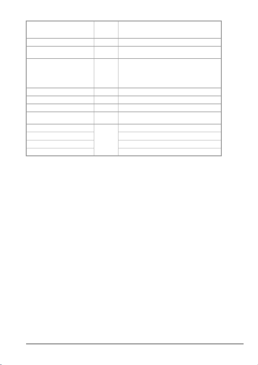
10.2 METRATESTER 5+ Test Instrument
Measuring Qty. Measuring Range Resolution U
Protective
conductor
resistance
Insulation
resistance
Equivalent
leakage current,
Contact current
(verification of
absence of voltage by means of
current measurement)
Differential
current
0 19.99 10 m < 20 V — > 200 mA
0.05 19.99 M 10 K 600 V Approx.
0 19.99 mA 10 A 28 V 2k <20mA —
0 1.999 mA 1 A2k
0,01 19.99 mA ~ 10 A
no-load
R
i
100 k
I
K
<10mA > 1 mA
Measurements During Operation
Measuring Quantity Measuring Range Resolution
Line voltage 207 253 V ~ 1 V
Load current via mains outlet 0 16.00 A ~ 10 mA
Overload Capacity
Load current via mains outlet, differential current 19 A, 5 min.
All other measured quantities 250 V continuous
Intrinsic Uncertainty and Measuring Uncertainty
Measured Quantity Intrinsic Uncertainty Measuring Uncertainty
Protective conductor resistance
Insulation resistance, 0 19.99 M
Equivalent leakage current
Verification of absence of voltage by means
of current measurement (contact current)
Differential current
Line Voltage
Load current via mains outlet
(2.5% rdg. + 2 d) (10% rdg. + 5 d)
(2.5% rdg. + 2 d) (10% rdg. + 5 d)
(2.5% rdg. + 2 d) (10% rdg. + 5 d)
(2.5% rdg. + 2 d) (10% rdg. + 5 d)
(4% rdg. + 5 d) (10% rdg. + 5 d)
(2.5% rdg. + 2 d) (10% rdg. + 5 d)
(2.5% rdg. + 2 d) (10% rdg. + 5 d)
I
N
Reference Conditions
Ambient temp. + 23 C 2K
Relative humidity 40 60%
Line voltage 230 V 1%
Measured quantity
frequency 50 Hz 0.2 %
Measured quantity
waveshape Sine (deviation between effective and rectified value: 0.5%)
22 GMC-I Messtechnik GmbH
Influencing Quantities and Influence Error
Influencing Quantity /
Sphere of Influence
Change of position E1
Change to test equipment supply
voltage
Temperature fluctuation
0 21 C and 25 40 C
Amount of current at DUT E4
Low frequency magnetic fields E5
DUT impedance I6
Capacitance during insulation
measurement
Waveshape of measured current
49 51 Hz
45 100 Hz
Designation
per DIN VDE
0404
E2
E3
E7
E8
Influence Error
% of the measured values
—
2.5
Specified influence error valid starting with
temperature changes as of 10 K:
1 for protective conductor resistance
0.5 for all other measuring ranges
2.5
2.5
2.5
2.5
2 with capacitive load (for equiv. leakage current)
1 (for contact current)
2.5 for all other measuring ranges
Display and Indicating Devices
LCD
Display range 0 1999 digits, 3½ places
Character height 17 mm and special characters
Overflow Indicated by displaying “OL”
Overtemp. R
ISO
PE Indicator Lamp
Indicates whether or not voltage is present.
In case of long-term short-circuit:
“R
” and “M” segments blink
ISO
Error Lamp
The red error lamp indicates exceeded limit values when measuring protective conductor
current, insulation resistance, equivalent leakage current, contact current, leakage current
and differential current.
Piezo Buzzer
In the event that the error lamp lights up in order to indicate that the respective critical limit
value has been exceeded, the buzzer also generates an acoustic signal.
Power Supply
Line voltage 230 V / 50 Hz
Throughput rating Max. 3700 VA, depending upon load at the mains outlet
GMC-I Messtechnik GmbH 23

Electrical Safety
Protection class II
Nominal line voltage 230 V
Test Voltage Mains + PE (mains) + 2 mA socket for testing for absence of voltage
at test socket, connector sockets for phase and protective
conductors, as well as clip: 3 kV mains to PE (mains) + 2 mA socket
1.5 kV
Measuring category
II
Pollution degree 2
Safety shutdown If test instrument overheats
Electromagnetic Compatibility (EMC)
Product standard EN 61326-1: 2006
Interference Emission Class
EN 55022 A
Interference Immunity Test Value Feature
EN 61000-4-2
EN 61000-4-3 10 V/m B
EN 61000-4-4
EN 61000-4-5
EN 61000-4-6 Mains connection – 3 V B
EN 61000-4-11 0.5 period / 100% A
Contact/atmos. – 4 kV / 8 kV
Mains connection – 2 kV
Mains connection – 1 kV
B
B
A
Ambient Conditions
Operation 10 ... + 55 C
Storage 25 ... + 70 C
Humidity Max. 75%, no condensation allowed
Elevation To 2000 m
Mechanical Design
Dimensions W x H x D: 190 x 140 x 95 mm
Weight 1.3 kg
Protection Housing: IP 40, connections: IP 20
Table Excerpt Regarding Significance of IP Codes
IP XY
st
char. X)
(1
0 not protected 0 not protected
1 50.0 mm diameter 1 vertically falling drops
2 12.5 mm diameter 2 vertically falling drops with
3 2.5 mm diameter 3 spraying water
4 1.0 mm diameter 4 splashing water
24 GMC-I Messtechnik GmbH
Protection against
foreign object entry
IP XY
(2nd char. Y)
Protection against the
penetration of water
enclosure tilted 15°

11 Maintenance – Recalibration
Note!
Note!
11.1 Housing Maintenance
No special maintenance is required. Keep outside surfaces clean and dry. Use a slightly
dampened cloth for cleaning. Avoid the use of solvents, cleansers and abrasives.
If the test case has not been used for a long period of time, the switches may
demonstrate increased contact resistance depending upon storage conditions.
If this is the case, actuate the switches several times.
11.2 Recalibration
The respective measuring task and the stress to which your measuring instrument is subjected affect the ageing of the components and may result in deviations from the guaranteed
accuracy.
If high measuring accuracy is required and the instrument is frequently used in field applications, combined with transport stress and great temperature fluctuations, we recommend a
relatively short calibration interval of 1 year. If your measuring instrument is mainly used in the
laboratory and indoors without being exposed to any major climatic or mechanical stress, a
calibration interval of 2-3 years is usually sufficient.
During recalibration* in an accredited calibration laboratory
(DIN EN ISO/IEC 17025) the deviations of your instrument in relation to traceable standards
are measured and documented. The deviations determined in the process are used for correction of the readings during subsequent application.
We are pleased to perform DAkkS or factory calibrations for you in our calibration laboratory.
Please visit our website at www.gossenmetrawatt.com ( Company DAkkS Calibration
Center or FAQs Calibration questions and answers).
By having your measuring instrument calibrated regularly, you fulfill the requirements of a
quality management system per DIN EN ISO 9001.
These tests can be performed on-site with the SECU-cal 10 calibration adapter
accessory.
*
Verification of specifications or adjustment services are not part of the calibration. For products from
our factory, however, any necessary adjustment is frequently performed and the observance of the relevant specification is confirmed.
GMC-I Messtechnik GmbH 25

11.3 Periodic Self-Test of the Connector Cable for Protective Conductor Continuity
Connect the probe cable (21) to a grounding contact which has been previously tested for
absence of voltage (e.g. at an electrical outlet), and which is connected to the protective
conductor in the connector cable, and set the NETZ-VDE switch (1) to “NETZ”. Then
measure protective conductor resistance as described in section 5.4. If an excessively high
protective conductor resistance value is displayed at the LCD panel or if overloading is
indicated (only “O.L” appears), protective conductor resistance is too high or the protective
conductor is interrupted. Eliminate the interruption (in the cable or at the NETZ-VDE switch).
11.4 Testing the Integrated RCD (residual current circuit breaker)
Test on a regular basis. The integrated RCD (residual current circuit breaker) can be tested
by pressing the test key. Breaking current value and time can be measured with test
instruments for DIN VDE 0413, part 6.
11.5 Fuse Replacement
All fuses can be accessed from outside. Only fuses with the breaking characteristics and
rated current values specified on the front panel may be used.
11.6 Return and Environmentally Sound Disposal
The METRATESTER 5+3P is a category 9 product (monitoring and control instrument) in
accordance with ElektroG (German electrical and electronic device law). This device is not
subject to the RoHS directive.
In accordance with WEEE 2002/96/EG and ElektroG, we identify our electrical
and electronic devices (as of Aug. 2005) with the symbol in accordance with
DIN EN 50419 which is shown at the right. Devices identified with this symbol
may not be disposed of with the trash.
Please contact our service department regarding the return of old devices (see
address below).
26 GMC-I Messtechnik GmbH

12 Repair and Replacement Parts Service
Calibration Center * and Rental Instrument Service
If required please contact:
GMC-I Service GmbH
Service Center
Thomas-Mann-Str. 20
90471 Nürnberg, Germany
Phone +49 911 817718-0
Fax +49 911 817718-253
E-mail service@gossenmetrawatt.com
www.gmci-service.com
This address is only valid in Germany. Please contact our representatives or subsidiaries for
service in other countries.
* DAkkS Calibration Laboratory for Measured Electrical Quantities
D-K-15080-01-01 accredited per DIN EN ISO/IEC 17025:2005
Accredited measured quantities: direct voltage, direct current values, DC resistance, alternating voltage, alternating
current values, AC active power, AC apparent power, DC power, capacitance, frequency and temperature
Competent Partner
GMC-I Messtechnik GmbH is certified in accordance with DIN EN ISO 9001:2008.
Our DAkkS calibration laboratory is accredited by the Deutscher Kalibrierdienst (German Calibration Service) in accordance with DIN EN ISO/IEC 17025:2005 under registration number
D-K-15080-01-01.
We offer a complete range of expertise in the field of metrology: from test reports and factory
calibration certificates, right on up to DAkkS calibration certificates.
Our spectrum of offerings is rounded out with free test equipment management.
An on-site DAkkS calibration station is an integral part of our service department. If errors are
discovered during calibration, our specialized personnel are capable of completing repairs
using original replacement parts.
As a full service calibration laboratory, we can calibrate instruments from other
manufacturers as well.
GMC-I Messtechnik GmbH 27

13 Product Support
If required please contact:
GMC-I Messtechnik GmbH
Product Support Hotline
Phone +49 911 8602-112
Fax +49 911 8602-709
E-mail support@gossenmetrawatt.com
Edited in Germany • Subject to change without notice • PDF version available on the Internet
GMC-I Messtechnik GmbH
Südwestpark 15
90449 Nürnberg •
Germany
Phone: +49 911 8602-111
Fax: +49 911 8602-777
e-mail: info@gossenmetrawatt.com
www.gossenmetrawatt.com
 Loading...