

Page 1
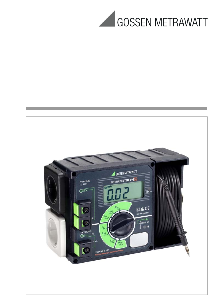
Operating Instructions
METRATESTER 5+
Tester for DIN VDE 0701-0702
3-348-580-15
28/9.16
Page 2
(8) (9) (10) (11) (12)
(7)
(6)
(5)
(4)
(3)
(2)
(1)
(13)
(3a)
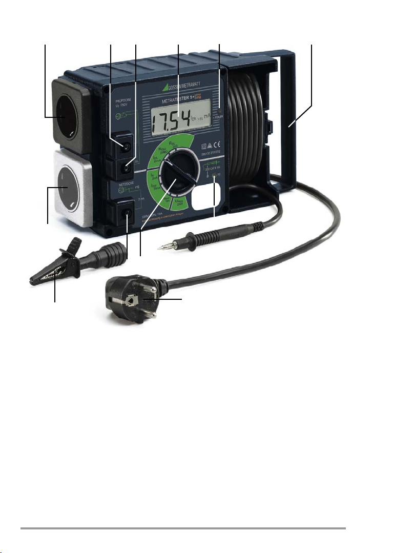
(1) Mains plug
(take-up spool at back of housing
for mains cable)
(2) Signal lamp PE for testing the
mains protective conductor
(3) Alligator clips for attachment
to the test probe (3a)
(3a) Test probe
(4) Contacting surface for contact finger
(5) Measuring function selector switch
R
Protective Conductor Resistance
SL
R
Insulation Resistance
ISO
I
Equivalent Leakage Current
EA
I
Contact or Leakage Current
A
(for confirmation of absence of voltage)
I
Residual Current
Diff
I
Load current at mains outlet
Netz
U
Mains Voltage
Netz
(6) Connector jack/terminal for testing for
contact current at conductive parts at
the DUT
(7) Mains outlet
(8) Test socket
(9) Connector jack/terminal for DUT
phase conductors (wired parallel
to the socket)
(10) Connector jack/terminal for DUT
protective conductor (wired parallel
to test socket)
(11) LCD display (description see page 24)
(12) Carrying handle
(13) Error lamp
2 GMC-I Messtechnik GmbH
Page 3
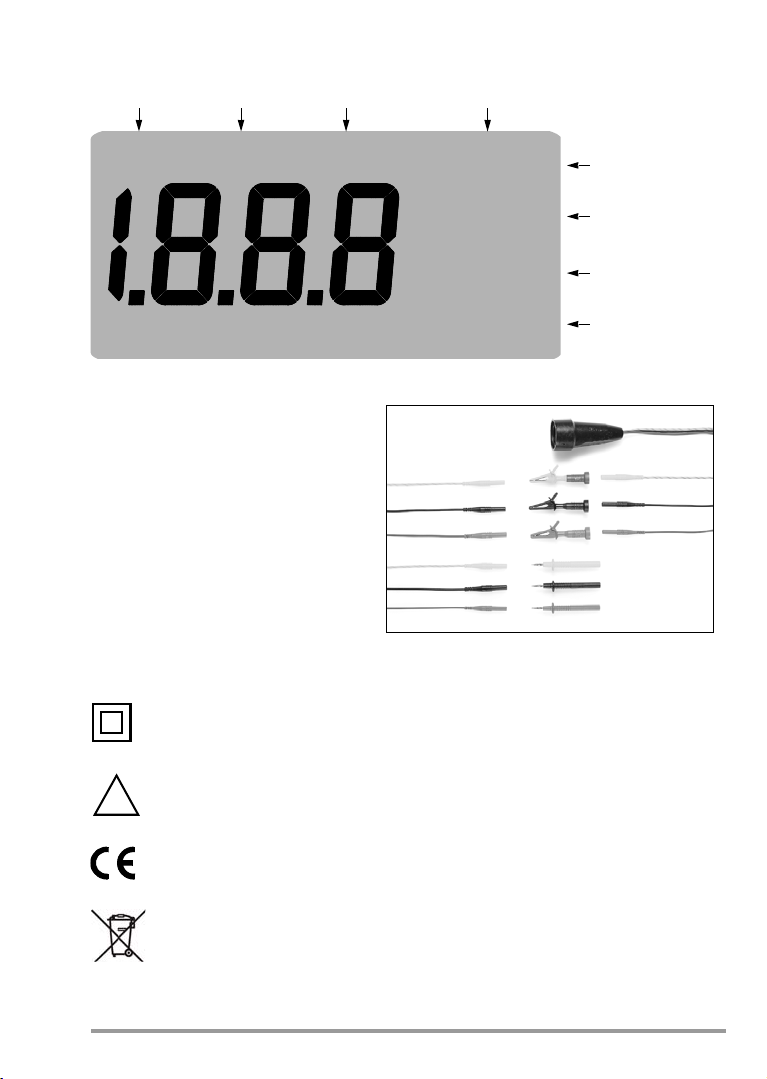
Display
I
Diff
mA I
Netz
A
MΩ
R
SL
>0.3
>1.0
R
ISO
<0.5
<2.0
I
EA
>7.0
I
A
>0.25
>0.5
mA
mA
Ω
I
Diff
mA I
Netz
AU
Netz
V
Insulation
Resistance
PE
Resistance
Equivalent
Leakage Current
Leakage Current/
Contact Current
Residual
Current
Secondary
Current
Indication of Limit Values
Mains
Voltage
KS 13 Accessory Cable Set
!
Display text subject to change without notice.
Meanings of Symbols on the Instrument
GMC-I Messtechnik GmbH 3
Continuous, doubled or reinforced
insulation
Warning concerning a point of danger
(attention: observe documentation!)
Indicates EC conformity
This device may not be disposed with the trash. For further details on the WEEE
marking, please refer to our website www.gossenmetrawatt.com and enter
search key ’WEEE’.
Page 4

Contents Page
1 Safety Features and Precautions ..................................................................................5
2 Applications ...................................................................................................................6
3 Operating and Display Elements ...................................................................................6
3.1 Error and Limit Value Messages ....................................................................................................... 8
4 Mains Connection .......................................................................................................... 9
4.1 Connecting the Tester ...................................................................................................................... 9
4.2 Testing Protective Conductor Potential ............................................................................................. 10
4.3 Measuring Mains Voltage ................................................................................................................ 10
4.4 Connecting the Device Under Test to the Test Instrument ................................................................. 11
4.4.1 DUT with protectiv conductor ( Safety Class I) and Mains Plug .......................................................... 11
4.4.2 Safety Class II DUT ........................................................................................................................ 11
4.4.3 DUT Without Mains Plug or Safety Class III DUT ............................................................................... 11
4.4.4 3-Phase DUT ................................................................................................................................. 11
4.5 General Measuring Procedures ....................................................................................................... 12
4.6 Residual Current Monitoring ............................................................................................................ 12
5 Testing Devices per DIN VDE 0701-0702 ....................................................................13
5.1 General ......................................................................................................................................... 13
5.2 Visual Inspection ............................................................................................................................ 14
5.3 Measuring Protective Conductor Resistance ..................................................................................... 14
5.3.1 Special case: permanently connected instruments ...........................................................................15
5.4 Measuring Insulation Resistance ..................................................................................................... 16
5.5 Measurement of protective conductor current ................................................................................. 17
5.5.1 Measuring Equivalent Leakage Current ............................................................................................ 18
5.5.2 Measuring Residual Current ............................................................................................................ 18
5.6 Measuring Contact Current ............................................................................................................. 19
5.6.1 Measuring Equivalent Leakage Current ............................................................................................ 19
5.6.2 Measuring Residual Current ............................................................................................................ 20
5.6.3 Direct Method ................................................................................................................................ 21
6 Measuring Load Current from the Mains Outlet .......................................................... 22
7 Technical Data ............................................................................................................23
8 Maintenance – Calibration ..........................................................................................26
9 Repair and Replacement Parts Service
Calibration Center and Rental Instrument Service ......................................................27
10 Product Support ..........................................................................................................28
4 GMC-I Messtechnik GmbH
Page 5
1 Safety Features and Precautions
Attention!
!
The tester is manufactured and tested in accordance with the following standards:
IEC/EN 61010-1/VDE 0411-1
and
DIN VDE 0404-1/-2: Testing and measuring equipment for checking the electric safety
When used for its intended purpose, the safety of the user, the test instrument and the device
under test (electrical equipment) is assured.
Read the operating instructions carefully and completely before placing your test instrument into service, and follow all instructions contained therein. Make sure that the operating instructions are available to all users of the instrument.
The tests may only be conducted under the supervision of a qualified electrician. The user must be instructed by a qualified electrician in the performance and evaluation of the test.
Observe the following safety precautions:
• The instrument may only be connected to electrical supply systems with 230 V/240 V
which conform to the valid safety regulations (e.g. IEC 60364, VDE 0100) and are protected with a fuse or circuit breaker with a maximum rating of 16 A.
• No measurements within electrical systems are allowed.
• Be prepared for the occurrence of unexpected voltages at devices under test. For example, capacitors may be dangerously charged.
• Make certain that connector cables are not damaged, e.g. damaged insulation, interruptions etc.
Devices under test may only be connected to the mains outlet after they have
successfully completed safety testing in accordance with DIN VDE 0701-702!
Opening of Equipment / Repair
The equipment may be opened only by authorized service personnel to ensure the safe and
correct operation of the equipment and to keep the warranty valid.
Even original spare parts may be installed only by authorized service personnel.
In case the equipment was opened by unauthorized personnel, no warranty regarding personal safety, measurement accuracy, conformity with applicable safety measures or any consequential damage is granted by the manufacturer.
Repair, Parts Replacement and Balancing
Voltage conducting parts may be exposed when the device is opened. The device must be
disconnected from all sources of voltage before repair, replacement of parts or balancing. If
repair or balancing of an open, live device cannot be avoided, this may only be performed by
trained personnel who are familiar with the dangers involved.
Errors and Extraordinary Strains
If it may be assumed that the device can no longer be operated safely, it must be removed
from service and secured against unintentional use. Safe use can no longer be relied upon,
• if the device demonstrates visible damage,
• if the device no longer functions,
• after lengthy periods of storage under unfavorable conditions.
Safety regulations for electrical measuring, control,
regulating and laboratory devices – general requirements
of electric devices; Part 1: general requirements, and Part 2:
Testing equipment for tests after repair, change or in case of repeat tests
GMC-I Messtechnik GmbH 5
Page 6

2 Applications
Note!
The tester is intended for the testing and measurement of repaired or modified electrical
devices in accordance with DIN VDE 0701-702. These regulations require the measurement
of protective conductor resistance, insulation resistance and equivalent leakage current for
repaired or modified electrical devices, as well as testing for the absence of voltage at
exposed, conductive parts for data processing systems and office machines.
Testing for the absence of voltage at the mains connection protective conductor and line voltage measurements can also be performed with this instrument. The device under test can be
connected to mains power at the mains outlet integrated into the tester, which provides for
the measurement of power consumption and the testing of functions.
Limit values displayed at the instrument make reference to periodic testing requirements set forth in VDE 0702: 1995.
3 Operating and Display Elements
(1) Mains Plug
The tester is connected to the 230 V mains outlet with the mains plug. If no earthing contact
socket is available, or if only three-phase current is available, the KS13 cable set can be used
to establish a connection.
The mains connection must be fused. Maximum nominal rating: 16 A!
(2) PE Signal Lamp for Protective Conductor Testing
The PE signal lamp lights up, if a potential difference of ≥ 100 V occurs
between the contacting surface (4) and the earthing contact at the mains plug (1).
(3) Alligator clip (gripper clip for attachment to the test probe)
Connect the housing of the device under test with the alligator clip for measurement of protective conductor resistance.
(4) Contacting Surface for Contact Finger
The PE signal lamp (2) lights up, if a potential difference of ≥ 100 V occurs between the PE
protective conductor at the mains plug (1) and the contacting surface.
The contacting surface is electrically isolated from all terminals, as well as from the measuring
circuit, and thus conforms to protection class II!
(5) Measuring Function selector Switch
Measuring functions can be selected with the measuring function selector switch. Displayed
values at intermediate switch positions have no significance.
(6) Connector Jack/Terminal for Measurement of Contact Current at Conductive
Components at the Device Under Test
This terminal is intended for the measurement of contact current at exposed conductive parts
which are not connected to the protective conductor.
(7) Mains Outlet
The DUT can be connected to the integrated mains outlet for the measurement of power
consumption and functions testing.
Residual current measurement is performed in this way as well.
Overcurrent protection is provided by the mains fuse or circuit breaker, see (1).
6 GMC-I Messtechnik GmbH
Page 7

(8) Test Socket
The DUT is connected to the test socket for the measurement of protective conductor resistance, insulation resistance and equivalent leakage current in accordance with
DIN VDE 0701-0702, if the DUT is equipped with a mains plug.
(9) Connector Jack/Terminal for DUT Phase Conductors
This terminal is wired in parallel to the two short-circuited phase conductor terminals at the
test socket (8). The DUT phase conductors can be connected to this jack/terminal, if the DUT
is not equipped with a mains plug.
(10) Connector Jack/Terminal for DUT Protective Conductor
This terminal is wired in parallel to the protective conductor terminal at the test socket (8). The
DUT protective conductor can be connected to this jack/terminal, if the DUT is not equipped
with an earthing contact plug. Beyond this, exposed conductive parts at the device under
test must be connected to this jack for insulation testing and the measurement of equivalent
leakage current.
(11) LCD Display
Measured values are displayed in digital form at the LCD.
(12) Carrying Handle
The carrying handle can be folded out.
(13) Error Lamp
The red error lamp indicates that limit values have been exceeded during the measurement of
protective conductor and insulation resistance, equivalent leakage, contact and leakage current, as well as residual current.
KS 13 Accessory Cable Set
The KS 13 cable set consists of a adapter socket with three permanently connected cables,
3 measurement cables, 3 plug-on pick-off clips and 2 plug-on test probes. With the KS 13
the tester and the DUT can be connected, even if no earthing contact socket is available for
the mains connection, or no earthing contact plug is present at the DUT.
GMC-I Messtechnik GmbH 7
Page 8
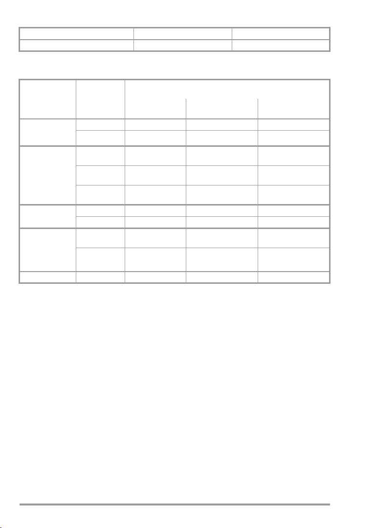
3.1 Error and Limit Value Messages Error Message Condition PE Signal Lamp
Protective conductor potential, at mains U
> 100 V If contact surface is contacted
B
The following limit values are indicated
Measurement
Error
Condition per
Standard
1)
Protective
Conductor
Resistance
Insulation
Resistance
Equivalent
Leakage Current
Leakage/Contact
Current
(Substantiation
of Absence of
Voltage)
Residual Current I
1)
Resistance between housing and mains plug in connector cables up to a length of 5 m
2)
For extension cables, there is an additional resistance of 0.1 Ω for each
additional 7.5 m, up to a maximum, however, of 1 Ω
3)
For safety class I devices with activated heating elements
(if heating power > 3 kW and R
leakage current measurement required)
4)
Limit value per DIN VDE 0702:1995
5)
This limit value applies for all-pole swit ches
(corresponds to a doubling of the limit value
or, respectively, a 50 % reduction of the actual measuring current)
>0.3Ω
R
SL
R
R
ISO
R
ISO
R
ISO
I
EA
2)
>1Ω
SL
3)
:
Heating
<0.3MΩ
SCI:
<1.0MΩ
SCII:
<2.0MΩ
>3.5mA • ——
Part 240:
>0.25mA
I
A
I
>0.5mA • >0.5mA •
A
≥ 3.5 mA • — •
Diff
< 0.3 MΩ:
ISO
Test Instrument Indicates When Limit Values
Red Error Lamp
Continuously Lit
Are Exceeded
Limit Values are
Displayed
• >0.3Ω —
• >1Ω•
• <0.5MΩ
• <2.0MΩ —
—<2.0MΩ —
• >7.0mA
• >0.25mA —
4)
5)
Continuous Acoustic
Signal (Beeper)
•
•
Residual Current Limit Value Violations
The METRATESTER 5 is equipped with a selector switch independent, residual current monitoring
function. If the red error lamp lights up and no message regarding a limit value violation
appears at the display, residual current at the mains outlet is dangerously high – regardless of
the selector switch setting. If this is the case, it is advisable to measure residual current (differential current) by turning the selector switch to the “I
Only the displayed numeric value should be considered when evaluating residual current with
the selector switch in the “I
of residual current monitoring for values of as low as approximately 3.2 mA. The error lamp
” position. The error lamp may be caused to light up as a result
DIFF
” position.
DIFF
lights up in any case as of 3.5 mA.
8 GMC-I Messtechnik GmbH
Page 9
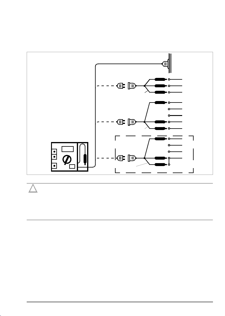
4 Mains Connection
Attention!
!
KS13
KS13
KS13
yellow-green
yellow-green
yellow-green
only possible in TN-C systems
L1
N
PE
L1
L2
L3
N
PE
L1
L3
N
L2
4.1 Connecting the Tester
➭ Connect the tester to the 230 V mains with the mains plug (1). If no earthing contact
socket is available, or if only a three-phase socket is available, connection of the phase
conductors, the neutral conductor and the PE conductor can be accomplished with the
help of the adapter socket. It includes 3 permanently connected cables and is included
with the KS 13 accessory cable set.
The instrument may only be connected to electrical supply systems with 230 V/
240 V which conform to the valid safety regulations (e.g. IEC 60364, VDE 0100) and
are protected with a fuse or circuit breaker with a maximum rating of 16 A.
The pick-off clips on the cables at the adapter socket may only be connected in the
voltage-free condition!
If mains voltage is present, characters are displayed at the LCD regardless of the position of
the measuring function selector switch, even if no DUT has been connected. Thus the presence of characters at the display indicates the presence of voltage – independent of measuring function selector switch position.
The mains voltage value is indicated at the display in the “U
tion. In all other switch detent positions, characters are displayed which have no correlation
to a measured value, if a DUT has not been connected.
250 V” selector switch posi-
Netz
GMC-I Messtechnik GmbH 9
Page 10

4.2 Testing Protective Conductor Potential
Note!
Note!
Attention!
!
➭ Bring the contact finger into contact with the contacting surface (4) and, at the same
time, with a grounded object (e.g. a water pipe).
The PE signal lamp (2) must not light up! Potential between the mains plug protective
conductor (1)
and the contacting surface (4) is then ≤ 100 V.
The PE signal lamp (2) does not light up, if no mains voltage is present between L and
N at the mains plug (1), or if L and PE are reversed at the mains connection. If, after
having connected the DUT in accordance with chapter 4.1, page 9, you determine,
that no characters are displayed at the LCD, the mains connection should first be
inspected – e.g. with the PROFITEST MASTER tester.
However, if the PE signal lamp (2) lights up when contact is made with the contacting surface
(4), potential between the protective conductor at the mains plug (1) and the contacting surface (4) is > 100 V, i.e. voltage is present at the protective conductor or the protective conductor is not connected.
Stray voltages may occur due to handling of the DUT, which cause the PE signal lamp
(2) to light up. For example, this may occur if a device is held in the hand which has
been connected to the test socket (8) due to the resultant occurrence of a capacitive
voltage divider. Touch a grounded object as described above in this case.
Voltage at the mains protective conductor (phase conductor L at protective earth
conductor PE: incorrect wiring of mains socket ) also distorts measured values for
the following tests:
– Measurement of contact current per DIN VDE 0701-0702
– Residual current measurement
4.3 Measuring Mains Voltage
➭ Set the measuring function selector switch to “U
Netz
250 V”
➭ Read the measured value at the LCD.
Mains voltage must lie within the allowable range of 207 to 253 V.
10 GMC-I Messtechnik GmbH
Page 11

4.4 Connecting the Device Under Test to the Test Instrument
To test socket
Switch the DUT on!
To housing for measurement of protective conductor resistance
R
SL
I
EA
R
ISO
Test cable, e.g. KS17-4
Switch the DUT on!
To test socket
To e xpos ed met al
parts
I
EA
R
ISO
N
L1
PE
e.g. KS17-4
Switch the DUT on!
To housing for measurement of protective conductor resistance
SCII I
R
SL
I
EA
R
ISO
N
L1
L2
PE
L3
Switch the DUT on!
To housing for measurement of protective conductor resistance
R
SL
I
EA
R
ISO
e.g. KS17-4
The DUT must be connected to the test socket (8), or to the jacks or terminals (9 and 10)
which are connected in parallel to the test socket for the measurement of protective conductor
resistance, insulation resistance and equivalent leakage current. Terminal (9) is connected to the
short-circuited phase conductor jacks at the test socket (8), and terminal (10) is
connected to the earthing contact at the test socket (8). Use one of the following test setups,
depending upon the type of device under test.
4.4.1 DUT with protectiv conductor ( Safety Class I) and Mains Plug
4.4.2 Safety Class II DUT
4.4.3 DUT Without Mains Plug or Safety Class III DUT
4.4.4 3-Phase DUT
GMC-I Messtechnik GmbH 11
Page 12

4.5 General Measuring Procedures
Note!
Attention!
!
Limit Value MΩ
Minimum Display Value
0,25 0,33
0,3 0,38
0,5 0,60
1,0 1,15
2,0 2,25
7,0 7,75
10,0 11,05
Line voltage must lie within the allowable range of 207 to 253 V for all of the following measurements. This assures that the accuracy of displayed measured values corresponds with
the values specified under “Technical Data” (chapter 7, page 23).
Line voltage can be measured by setting the measuring function selector switch to the “U
250 V” position (see chapter 4.3, page 10).
Measuring ranges for the measurement of protective conductor resistance, insulation resistance, equivalent leakage current and contact current are protected against overload in the
event that interference voltages of up to 250 V are applied inadvertently.
Always start with the measurement of protective conductor resistance for safety class I
devices. Insulation resistance and equivalent leakage current cannot be measured if the protective conductor does not function properly. This connection must be established externally
for safety class II devices (see chapter 4.4.2).
Please note that overflow is indicated at the display during the measurement of protective conductor resistance and insulation resistance, if the terminals are open or if
the upper range limit is exceeded. In this case, only the character “1” is displayed at
the left-hand side of the LCD (11).
Measuring current is reduced after approximately 10 minutes in the event of a
long-term short-circuit during insulation testing. Excessive temperature is indicated at
the display in this case (see chapter 7 “Display – Excessive Temp.”). If this display appears, nominal current of 1 mA as required by DIN VDE 0413 is no longer assured.
After the short-circuit has been eliminated, and after a brief cool-down period, the
message is cleared from the display and subsequent
measurements once again fulfill VDE requirements.
Netz
Evaluating Measured Values
In order to make absolutely sure that limit values
for insulation resistance are not fallen short of,
instrument measuring error must be taken into
consideration. Minimum required display values
for insulation resistance can be taken from the
following table.These values take maximum service error into consideration (under nominal
conditions of use). The indicated values correspond to the required limit values
(DIN VDE 0413, part 1). Intermediate values can
be interpolated.
4.6 Residual Current Monitoring
For your safety, residual current at the DUT connected to the mains outlet is continuously
monitored by METRATESTER 5 instruments. If residual current reaches a value of greater
than 3.5 mA, danger is indicated by means of a continuous acoustic signal.
Automatic shutdown does not occur (see chapter 3.1, page 8).
12 GMC-I Messtechnik GmbH
Page 13

5 Testing Devices per DIN VDE 0701-0702
Attention!
!
Note!
The limit values specified in the following chapters correspond to current revision levels of
official standards at the time of going to print. Please note that normative legislation is continuously updated to meet the safety requirements necessitated by changing market situations,
and that the listed limit values are thus subject to change. Please contact our update service
department in order to adapt test instruments to new standards.
5.1 General
According to DIN VDE 0701-0702, repaired or modified electrical devices must provide users
with the same protection against electrical energy as is offered by new devices. The following
tests must be performed to this end, in the order indicated:
1 Visual inspection
2 Protective conductor resistance
3 Insulating characteristics:
if technically sensible, i.e. if the DUT does not include any all-pole,
electrically actuated switches:
– Insulation resistance followed by protective conductor current or equivalent leakage
current
– Other: leakage current during operation (protective conductor current and contact
current), safety extra-low voltage (only at connecting points for safety extra-low
voltage generated within the device under test)
4Function test
5 Labelling inspection
6Documentation
If any doubts exist concerning the performance of an insulation resistance
measurement, a differential current measurement can be performed in its place.
For example, this may be the case with electronic devices and data processing
equipment, or safety class I devices if it is assured that all components which are
charged with line voltage are covered by this measurement.
This measurement may only be performed after the protective conductor at the DUT
has been tested.
The device under test must be plugged into the mains outlet at the
METRATESTER 5 test instrument for measurement of residual current.
An RCCB may be tripped if measurement is performed at a defective device!
GMC-I Messtechnik GmbH 13
Page 14

5.2 Visual Inspection
To test socket
R
SL
To housing for measurement of protective conductor resistance
Visual inspection is performed prior to measurements with the test instrument.
Visual inspection includes:
• damage to connector cables;
• insulation damage;
• selection and application of conductors and plugs for their intended use;
• condition of mains plug, of connection terminals and wires;
• defects of bending protection;
• defects of connector cable strain relief;
• condition of fastenings, of conductor fixings, of the fuse holder which is accessible to the
user, etc.;
• damage to the housing and protective covers;
• signs of excessive strain or improper use/handling;
• signs of inadmissible tampering or modifications;
• fouling, corrosion or aging to a degree unduly impairing the safety of the instrument;
• fouling and/or clogging of openings for cooling purposes;
• condition of air filters;
• leakproofness of containers for water, air or other agents/fluids, condition of pressure
control valves;
• operation of switches, control and/or setting equipment, etc.;
• legibility of safety labels or symbols, of rated values and position indicators.
5.3 Measuring Protective Conductor Resistance
➭ In the case of instruments equipped with a protective conductor, connect the DUT as de-
scribed in the following picture.
here: dut (Safety class I) and mains plug, also see chapter 4.4, page 11.
➭ Set the measuring function selector switch to the “R
20 Ω” position.
SL
➭ Read the measured value in “Ω” from the LCD
➭ Move the cable from the DUT during the measurement, section by section over its entire
length, in order to locate interruptions.
Protective conductor resistance may not exceed the following values:
14 GMC-I Messtechnik GmbH
Page 15

Maximum Allowable Protective Conductor Resistance Values Depending upon Cable Length
Attention!
!
To housing for measurement of protective conductor resistance
R
SL
KS17-4
Length to [m] 5 12. 5 20 27.5 35 42.5 50
Max. resistance
[Ω]
0.3 0.4 0.5 0.6 0.7 0.8 0.9 1.0
more than 50
Under no circumstances may a value of 1 Ω be exceeded. The table is also valid for cable
reels and extension cables.
The alligator clip (3) must make good contact with the housing of the device under
test!
The connector cable must be moved during measurement, section by section over
its entire length – for permanently installed devices only in so far as the cable is accessible during repair, modification or testing. If the resistance value fluctuates during
this manual test which is essential for continuity testing, it must be assumed that the
protective conductor is damaged, or that one of its connection points is defective.
Defects of this type must be corrected before any further tests are performed.
5.3.1 Special case: permanently connected instruments
A resistance value of up to 1 Ω measured between a suitable earthing contact and all
exposed conductive parts which might become charged with voltage in the event of an error
is allowable for permanently installed devices.
In the case of data processing systems or combinations of permanently installed individual
devices, the network should be decoupled and individual measurements should be performed. If decoupling is not feasible, individual measurements may be performed at
interconnected devices.
GMC-I Messtechnik GmbH 15
Page 16

5.4 Measuring Insulation Resistance
Attention!
!
Attention!
!
R
iso
To test socket
R
iso
To test socket
To e xpos ed m et al
parts
KS17-4
This measurement may only be performed if the device under test has successfully completed protective conductor resistance testing. If the DUT is equipped with all-pole electrical switches, e.g.
undervoltage releases or relays, this test only covers the supply conductor. The device cannot be switched on without being connected to the mains, consequently, it cannot be subjected to an effective insulation test. For testing in conformance with VDE, it is necessary to
measure the leakage current under mains voltage.
Do not touch the instrument’s terminal contacts during insulation resistance measurements!
If nothing has been connected to the terminal contacts, or if a resistive load component has
been connected for measurement, your body would be exposed to a current of approx. 1 mA
at a voltage of 500 V. The resulting electrical shock is not life endangering. However, the
noticeable shock may lead to injury (e.g. resulting from a startled reaction etc.).
If measurement is performed at a capacitive object such as a long cable, it becomes
charged with up to approx. 500 V! Touching such objects is life endangering!
➭ Connect the DUT as shown in the following picture
Safety Class I
Safety Class II
➭ Set the measuring function selector switch to the “R
20 MΩ” range.
ISO
➭ Activate all functions of the DUT, and be certain, for example, that contacts for tempera-
ture sensitive switches and the like are also closed.
➭ Read the measured value in “MΩ” from the LCD (11).
Insulation resistance may not fall short of the following values:
16 GMC-I Messtechnik GmbH
Page 17

Attention!
!
Note!
Device Type Limit Value
10 10210310410510
6
+20
0
–20
–40
–60
Frequency (f) in Hz
Relative Quantity (dB): 20 log
U(f)
U(f=10)
Safety class I devices 1 MΩ 1.15 MΩ
Safety class I devices with heating elements 0.3 MΩ
1)
Minimum Display Value
0.38 MΩ
Safety class II devices 2.0 MΩ 2.25 MΩ
Safety class III devices and battery powered devices 1000 Ω/V or 250 kΩ
1)
Leakage current measurement must be performed if the applicable limit value is fallen short of.
Note: „OL“ means measured value > 20 MΩ.
If a value of 0.3 MΩ is fallen short of for safety class I devices with heating elements,
equivalent leakage current measurement must be performed and passed in accordance with chapter 5.6.1, page 19.
Each exposed conductive part must be contacted with the test probe connected to
the jack (10), and insulation resistance must be measured for safety class II and III
devices, and battery powered devices.
No insulation resistance measurement is required for safety class III devices, or for
battery powered devices which fulfill both of the following conditions:
– Nominal power ≤ 20 VA
– Nominal voltage ≤ 42 V.
Batteries must be disconnected during the performance of measurements at battery
powered devices.
Discharge of the DUT for the avoidance of electrical shocks
➭ After insulation resistance measurement on capacitive objects:
Set the measuring function selector switch one position further to the left to switch position „I
20 mA“, in accordance with the standard-compliant test sequence. The DUT is
EA
automatically discharged. Contact with the device under test must be maintained to this
end.
5.5 Measurement of protective conductor current
Protective conductor current must be measured
in instruments featuring a protective conductor/
earth-contact plug.
The following methods may be used for measurement:
• Measuring Equivalent Leakage Current
• Measuring Residual Current
Frequency response is taken into consideration
in accordance with the graph to the right during
leakage current measurement.
The following schematic diagrams refer to DUTs with a mains plug. See also
chapter 4.4
GMC-I Messtechnik GmbH 17
Page 18

5.5.1 Measuring Equivalent Leakage Current
Attention!
!
Note!
Note!
I
EA
To test socket
I
Diff
To test socket
Do not touch the instrument’s terminal contacts during equivalent leakage current measurements!
➭ Connect the DUT as shown in the followig picture.
➭ Set the measuring function selector switch to the “I
20 mA” position.
EA
➭ Switch all DUT functions on and make sure, for example, that all contacts for tempera-
ture sensitive switches and the like are closed.
➭ Read the measured value in “mA” from the LCD.
According to DIN VDE 0701-0702, the displayed value for current between components
to which voltage is applied during operation and exposed metal parts may not exceed
3.5 mA, or 1 mA/kW for devices with heating power of greater than 3.5 kW.
5.5.2 Measuring Residual Current
Residual current (differential current) is measured between phase conductor L and neutral
conductor N at the device under test. This measurement may not be performed until the
protective conductor test has been passed (see chapter 5.3, page 14).
➭ Connect the device under test to the mains outlet..
➭ Set the measuring function selector switch to the “I
20 mA” position.
Diff
➭ Start up the device under test.
➭ Read the residual current value in mA from the display. According to
DIN VDE 0701-0702, the displayed current value may not exceed 3.5 mA, or 1 mA/kW
for devices with heating power equal to or greater than 3.5 kW.
Measurements must be performed with the mains plug poled in both directions. The larger of
the two measured values applies.
If no device under test is connected, random characters appear at the digital display
which may not be construed as measured values.
If the METRATESTER 5 is integrated into a 3-phase ammeter, residual current is measured as the sum of instantaneous current in conductors L1, L2, L3 and N.
18 GMC-I Messtechnik GmbH
Page 19

5.6 Measuring Contact Current
Note!
Note!
Attention!
!
10 10210310410510
6
+20
0
–20
–40
–60
Frequency (f) in Hz
Relative Quantity (dB): 20 log
U(f)
U(f=10)
I
EA
To test socket
To exposed metal
parts
KS17-4
Contact current measurement can be performed instead of insulation resistance measurement for class II devices, or for class I devices with exposed conductive parts which are not
connected to the protective conductor.
• Measuring Equivalent Leakage Current
• Measuring Residual Current
•Direct Method
Frequency response is taken into
consideration in accordance with the graph
to the right during leakage current measurement.
Please note that the current in the protective conductor is also measured both in the
case of equivalent leakage current and in the case of differential current measurement.
The following schematic diagrams refer to DUTs with a mains plug. See also
chapter 4.4
5.6.1 Measuring Equivalent Leakage Current
Do not touch the instrument’s terminal contacts during equivalent leakage current measurements!
➭ Connect the DUT as shown in the following picture.
➭ Connect the cable with the test probe to the “SL” jack.
➭ Set the measuring function selector switch to the “I
➭ Switch all DUT functions on and make sure, for example, that all contacts for tempera-
ture sensitive switches and the like are closed.
➭ Contact all exposed metal parts at the device under test with the test probe.
➭ Read the measured value in “mA” from the LCD.
This value may not exceed 0.5 mA
GMC-I Messtechnik GmbH 19
20 mA” position.
EA
Page 20

5.6.2 Measuring Residual Current
Attention!
!
Note!
I
Diff
To exposed metal
parts
To the mains outlet
KS17-4
The protective conductor test must first be performed and passed.
➭ Connect the DUT as shown in the followig picture..
➭ Connect the cable with the test probe to the “2 mA” jack.
➭ Set the measuring function selector switch to the “I
20 mA” position.
Diff
➭ Start up the device under test.
➭ Contact all exposed metal parts at the device under test with the test probe.
➭ Read the residual current value in mA from the display. This value may not exceed
0.5 mA.
Measurements must be performed with the mains plug poled in both directions. The larger of
the two measured values applies.
If no device under test is connected, random characters appear at the digital display
which may not be construed as measured values.
20 GMC-I Messtechnik GmbH
Page 21

5.6.3 Direct Method
Note!
I
A
To the mains
To e xpos ed met al
parts
KS17-4
outlet
The DUT can remain connected to the mains or to the mains outlet for this test. When testing
in accordance with DIN VDE 0701-0702, DUTs with external connections such as data
cables etc. can be tested within their entire configuration at the installation site.
An RCCB may be tripped if measurement is performed at a defective device!
➭ Connect the DUT as shown in the following picture.
➭ Connect the cable with the test probe to the “2 mA” jack.
➭ Set the measuring function selector switch to the “I
2 mA” position.
A
➭ Start up the device under test.
➭ Contact all exposed metal parts at the device under test with the test probe.
➭ Read the residual current value in mA from the display. This value may not exceed
0.5 mA.
GMC-I Messtechnik GmbH 21
Page 22

6 Measuring Load Current from the Mains Outlet
Attention!
!
Attention!
!
To the mains outlet
I
Netz
The device under test may not be connected to the mains outlet (7) until is has
passed safety testing in accordance with DIN VDE 0701-0702, part 1!
➭ Connect the earthing contact plug from the device under test to the mains outlet (7).
➭ Set the measuring function selector switch to the “I
➭ Switch the device under test on.
➭ Read the measured value in “A” from the LCD (11).
16 A” position.
Netz
Maximum allowable load capacity is 16 A continuous and 20 A for up to 10 minutes.
The electrical system to which the test instrument is connected must be protected
against overload with a fuse or circuit breaker. The fuse or circuit breaker rating may
not exceed 16 A!
22 GMC-I Messtechnik GmbH
Page 23

7 Technical Data
Meas. Quantity Measuring Range Resolution U
NO-LOAD
R
I
i
I
K
N
PE Resistance 0 ... 19.99 Ω 10 mΩ < 20 V − — > 200 mA
Insulation
Resistance
Equivalent
Leak. Current
Confirmation of
absence of voltage with current
measurement
(contact or leakage current)
0,05 ... 19.99 MΩ 10 kΩ 600 V − approx.
100 kΩ
<10mA > 1 mA
0 ... 19.99 mA ∼ 10 μA 28 V ∼ 2kΩ <20mA —
0 … 1.999 mA ∼ 1 μA2kΩ
Residual Current 0.01 … 19.99 mA ~ 10 μA
Operational Measurements
Meas. Quantity Measuring Range Resolution
Mains Voltage 207 ... 253 V ~ 1 V
Load current at mains outlet 0 ... 16.00 A ~ 10 mA
Overload Capacity
Load current at mains outlet, residual current 19 A, 5 min.
All other measuring quantities 250 V continuous
Intrinsic and Measuring Uncertainty
Meas. Quantity Intrinsic Uncertainty Measuring Uncertainty
Protective Conductor Resistance
Insulation Resistance 0 ... 19.99 MΩ
Equivalent Leakage Current
Confirmation of absence of voltage with
current measurement (contact current)
Residual Current
Mains Voltage
Load current at mains outlet
± (2.5 % of rdg. + 2 D) ± (10 % of rdg. + 5 D)
± (2.5 % of rdg. + 2 D) ± (10 % of rdg. + 5 D)
± (2.5 % of rdg. + 2 D) ± (10 % of rdg. + 5 D)
± (2.5 % of rdg. + 2 D) ± (10 % of rdg. + 5 D)
± (4 % of rdg. + 5 D) ± (10 % of rdg. + 5 D)
± (2.5 % of rdg. + 2 D) ± (10 % of rdg. + 5 D)
± (2.5 % of rdg. + 2 D) ± (10 % of rdg. + 5 D)
Reference Conditions
Ambient
Temperature +23 °C ±2K
Relative Humidity 40 … 60%
Mains Voltage 230 V ±1%
Measured Quantity
Frequency 50 Hz ± 0.2 %
Measured Quantity
Waveshape sine (deviation between effective and rectified value ±0.5 %)
GMC-I Messtechnik GmbH 23
Page 24

Influence Variables and Errors
Influence Variable/
Sphere of Influence
Change in position E1
Change in supply voltage to the
test device
Temperature fluctuation
0 … 21 °C and 25 … 40 °C
Current at device under test E4
Low frequency magnetic fields E5
DUT impedance E6
Capacitance during insulation
measurement
Designation
per
DIN VDE
0404
E2 2.5
E3
E7
Influence Errors
± ... % of measured value
—
Indicated influence errors per 10 K temperature change:
1 with PE resistance
0.5 all other measuring ranges
2.5
2.5
2.5
2.5
Waveshape of the measured
current
49 … 51 Hz
45 … 100 Hz
2 with capacitive load (with equivalent leakage current)
E8
1 (with contact current)
2,5 all other measuring ranges
Display and Signalling Devices
LCD
Display Range 0 ... 1999 digits, 3½ places
Character Height 17 mm and special characters
Overflow indicated at display with “OL”
Excessive Temp. R
for long duration short-circuit:
ISO
segments “R
ISO
” and “MΩ” blink
PE Signal Lamp
Indicates whether or not voltage is present at the mains protective conductor.
Error Lamp
The red error lamp indicates that limit values have been exceeded during the measurement of
protective conductor or insulation resistance, equivalent leakage, contact or leakage current,
as well as residual current.
Piezoelectric Resonator
In the event that the error lamp lights up and the respectively more critical limit value is
exceeded, the piezoelectric resonator also sounds.
Power Supply
Mains Voltage 230 V/50 Hz
Throughput max. 3700 VA, dependent upon load at mains outlet
24 GMC-I Messtechnik GmbH
Page 25

Electrical Safety
Protection Class II
Nom. Mains Voltage 230 V
Test Voltage Mains + PE (mains) + 2 mA socket for testing for the absence of
voltage at test socket, connector jacks for phase and protective
conductors and gripper clip:
3kV∼ mains to PE (mains) + 2 mA socket: 1.5 kV∼
Measurement Category II
Pollution degree 2
Safety Cut-Off when device overheats
Electromagnetic Compatibility EMV
Product standards EN 61326-1:2006 class B
EN 61326-1:2006
Ambient Conditions
Operation − 10 ... + 55 °C
Storage − 25 ... + 70 °C
Atmosph. Humidity max. 75%
Elevation to 2000 m
Mechanical Design
Dimensions W x H x D: 190 mm x 140 mm x 95 mm
Weight 1.3 kg
Protection Housing IP 40, terminals IP 20
IP XY
st
(1
digit X)
Extract from table on the meaning of IP codes
Protection against
foreign object entry
IP XY
(2nd digit Y)
Protection against the
penetration of water
0 not protected 0 not protected
1 ≥ 50.0 mm
2 ≥ 12.5 mm
3 ≥ 2.5 mm
4 ≥ 1.0 mm
∅
∅
∅
∅
1 vertically falling drops
2 vertically falling drops
with enclosure tilted 15°
3 spraying water
4 splashing water
GMC-I Messtechnik GmbH 25
Page 26

8 Maintenance – Calibration
Maintenance Housing
No special maintenance is required. Keep outside surfaces clean and dry. Use a slightly
dampened cloth for cleaning. Avoid the use of solvents, cleansers or abrasives.
Recalibration
The respective measuring task and the stress to which your measuring instrument is subjected affect the aging of the components and may result in deviations from the guaranteed
accuracy.
If high measuring accuracy is required and the instrument is frequently used in field applications, combined with transport stress and great temperature fluctuations, we recommend a
relatively short calibration interval of 1 year. If your measuring instrument is mainly used in the
laboratory and indoors without being exposed to any major climatic or mechanical stress, a
calibration interval of 2-3 years is usually sufficient.
During recalibration* in an accredited calibration laboratory
(DIN EN ISO/IEC 17025) the deviations of your instrument in relation to traceable standards
are measured and documented. The deviations determined in the process are used for correction of the readings during subsequent application.
We are pleased to perform DAkkS or factory calibrations for you in our calibration laboratory.
Please visit our website at
www.gossenmetrawatt.com (→ Company → DAkkS Calibration Center or → FAQs → Cali-
bration questions and answers).
By having your measuring instrument calibrated regularly, you fulfill the requirements of a
quality management system per DIN EN ISO 9001.
Standards DIN VDE 0701-0702 and IEC 63353 (VDE 0751) stipulate that only measuring
instruments which are regularly tested and calibrated may be used for testing.
Device Return and Environmentally Compatible Disposal
The instrument is a category 9 product (monitoring and control instrument) in accordance with
ElektroG (German Electrical and Electronic Device Law).
This device is subject to the RoHS direc-
tive. Furthermore, we make reference to the fact that the current status in this regard can be accessed
on the Internet at www.gossenmetrawatt.com by entering the search term WEEE.
We identify our electrical and electronic devices in accordance with WEEE 2012/19/
EU and ElektroG with the symbol shown to the right per DIN EN 50419.
These devices may not be disposed of with the trash. Please contact our service
department regarding the return of old devices.
* Verification of specifications or adjustment services are not part of the calibration. For products from our factory, however,
any necessary adjustment is frequently performed and the observance of the relevant specification is confirmed.
26 GMC-I Messtechnik GmbH
Page 27

9 Repair and Replacement Parts Service
Calibration Center* and Rental Instrument Service
If required please contact:
GMC-I Service GmbH
Service-Center
Thomas-Mann-Strasse 20
90471 Nürnberg, Germany
Phone +49 911 817718-0
Fax +49 911 817718-253
E-Mail service@gossenmetrawatt.com
www.gmci-service.com
This address is only valid in Germany.
Please contact our representatives or subsidiaries for service in other countries.
* DAkkS Calibration Laboratory for Electrical Quantities D-K-15080-01-01
accredited per DIN EN ISO/IEC 17025
Accredited measuring quanities: Direct voltage, direct current intensity, direct current resistance,
alternating voltage, alternating current intensity, alternating current active power, alternating current
apparent power, direct current power, capacity, frequency and temperature
Competent Partner
GMC-I Messtechnik GmbH is certified in accordance with DIN EN ISO 9001.
Our DAkkS calibration laboratory is accredited by the Deutsche Akkreditierungsstelle GmbH
(National accreditation body for the Republic of Germany) in accordance with DIN EN ISO/
IEC 17025 under registration number D-K-15080-01-01.
We offer a complete range of expertise in the field of metrology: from test reports and propri-
etary calibration certificates right on up to DAkkS calibration certificates.
Our spectrum of offerings is rounded out with free test equipment management.
An on-site DAkkS calibration station is an integral part of our service department. If errors are
discovered during calibration, our specialized personnel are capable of completing repairs
using original replacement parts.
As a full service calibration laboratory, we can calibrate instruments from other manufacturers
as well.
GMC-I Messtechnik GmbH 27
Page 28

10 Product Support
If required please contact:
GMC-I Messtechnik GmbH
Product Support Hotline
Phone +49 911 8602-0
Fax +49 911 8602-709
E-Mail support@gossenmetrawatt.com
Edited in Germany • Subject to change without notice • A pdf version is available on the internet
Phone +49 911 8602-111
GMC-I Messtechnik GmbH
Südwestpark 15
90449 Nürnberg •
Germany
Fax +49 911 8602-777
E-Mail info@gossenmetrawatt.com
www.gossenmetrawatt.com
 Loading...