

Page 1
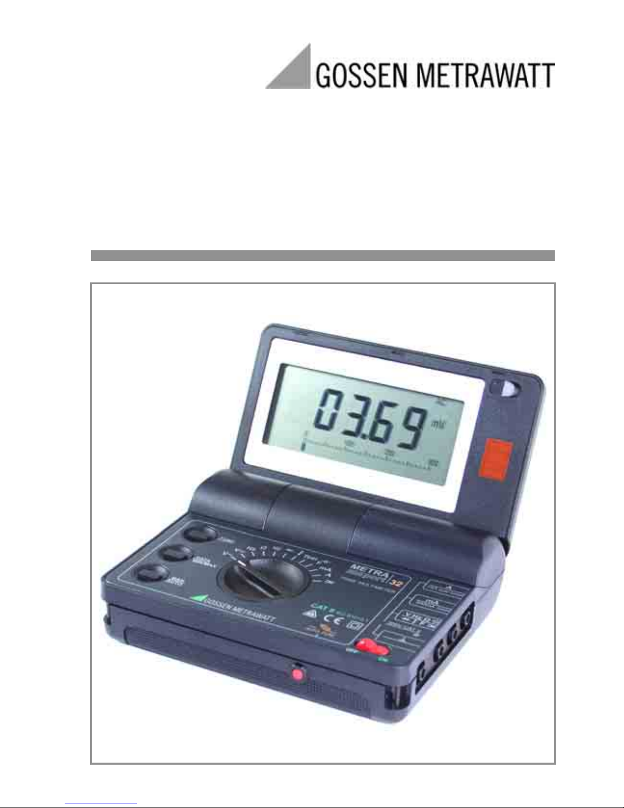
METRAport
32 XS
Digital Multimeter
3-349-281-02
6/3.04
Operating Instructions
Page 2
2 GOSSEN METRAWATT GMBH
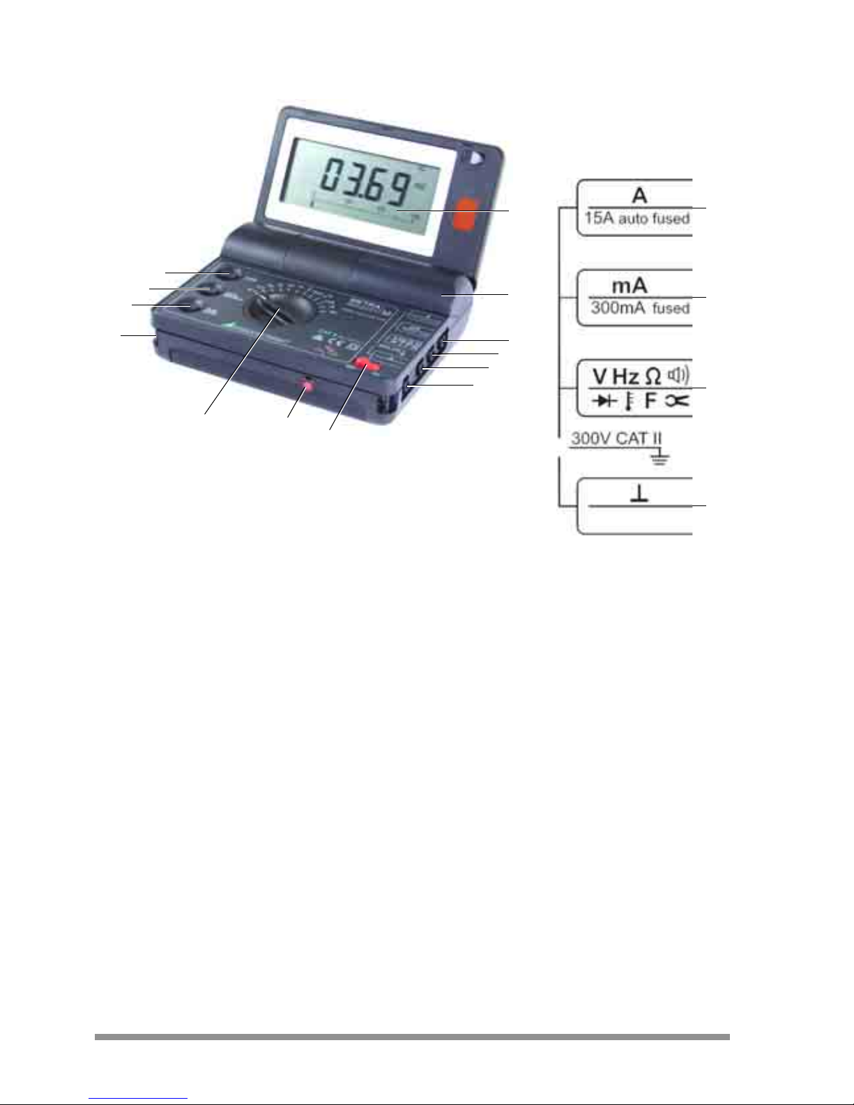
Control Elements
1LCD
2 Battery compartment cover
3 “Max. 15 A (max. 5 min)” connector jack for highest current range
4 “Max. 300 mA” connector jack for mA range
5 Connector jack for all measuring ranges except current measuring ranges
6“⊥” connector jack for all measuring ranges
7 OFF/ON: ON/OFF switch
8 Resettable miniature circuit breaker (AUTO FUSE)
9 Rotary switch for function selection
10 Eyelet for carrying strap
11 MAN/AUTO: Key for manual and automatic measuring range selection
12 DATA and MIN/MAX: Key for measured value storage
13 FUNC: Multifunction key
3
4
5
6
1
2
7
9
10
12
13
11
8
3
4
5
6
Page 3
GOSSEN METRAWATT GMBH 3
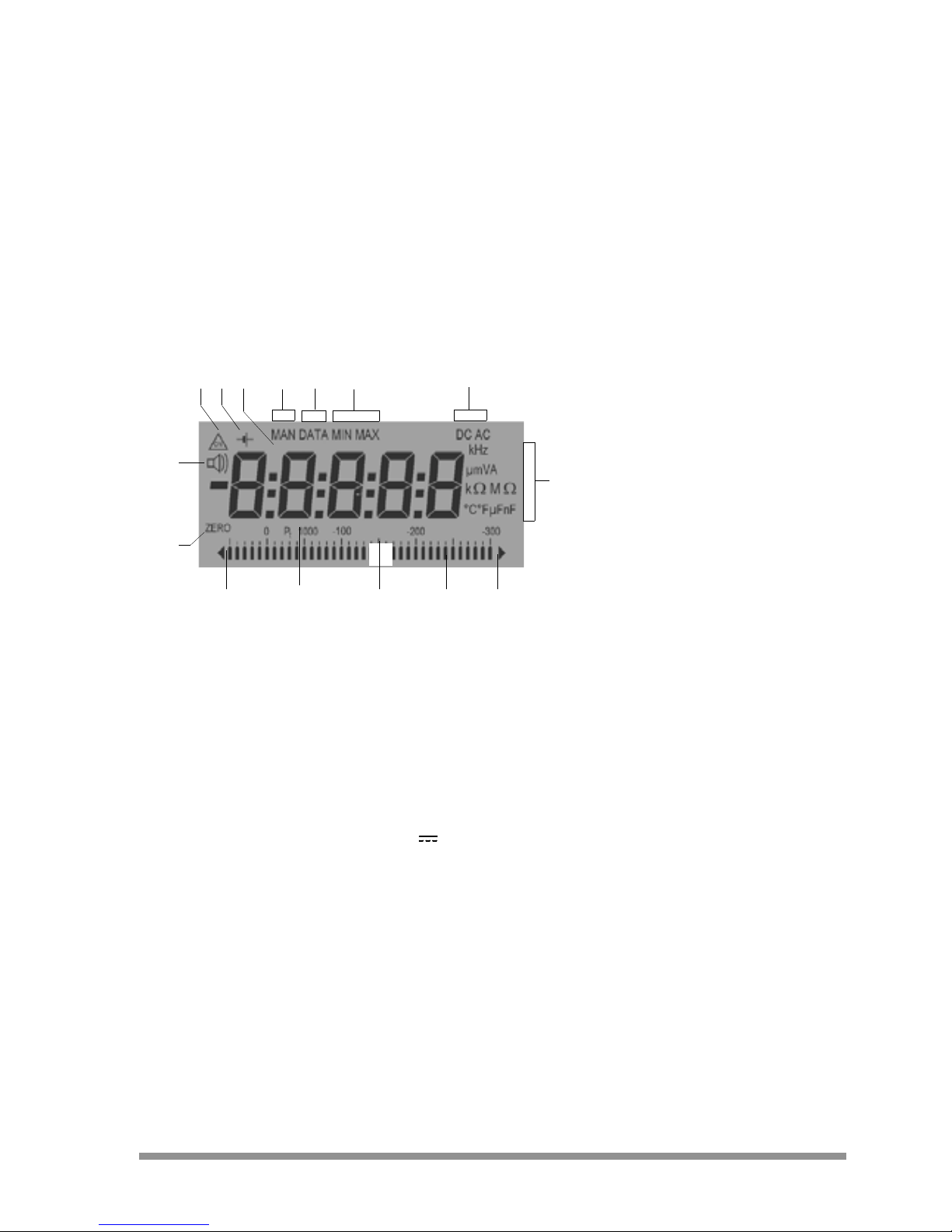
Digital Display Symbols
1 Continuous operation
2Low battery
3 Digital display with indication of decimal place and polarity
4 Manual measuring range selection
5 Display memory, “freeze measured value”
6MIN-MAX storage
7 Selected current type, DC
() or AC (~)
8Unit of measure
9Over-ranging
10 Pointer for analog display
11 Analog display scale
12 Resistance thermometer: Pt100 / Pt1000
13 Negative analog display range exceeded
14 Zero balancing active
15 Acoustic signal activated (e.g. for continuity testing)
134
7
8
9101113
14
15
5 62
12
Page 4

4 GOSSEN METRAWATT GMBH
Contents......................................................................................................................... Page
1 Safety Features and Precautions ............................................................................5
2 Initial Start-Up .........................................................................................................7
3 Selecting Measuring Functions and Measuring Ranges .........................................8
3.1 Automatic Measuring Range Selection ........................................................................8
3.2 Manual Measuring Range Selection – MAN/AUTO Key .................................................8
3.3 Quick Measurements .................................................................................................9
4 Display (LCD) ...........................................................................................................9
4.1 Digital Display ...........................................................................................................9
4.2 Analog Display ..........................................................................................................9
5 Measured Value Storage – DATA / MIN-MAX Key .................................................10
5.1 DATA (hold / compare) .............................................................................................10
5.2 Storage of Minimum and Maximum Values “MIN-MAX” with Time Stamp ....................11
6 Voltage Measurement ...........................................................................................12
6.1 Transient Overvoltages .............................................................................................13
6.2 Measuring Voltages of Greater than 300 V ................................................................13
7 Current Measurement ...........................................................................................13
7.1 Current Measurement with Current Transformers with Voltage Output ........................15
8 Resistance Measurement ......................................................................................16
9 Continuity Testing .................................................................................................16
10 Diode Testing ........................................................................................................17
11 Capacitance Measurement ...................................................................................18
12 Frequency Measurement ......................................................................................18
13 Temperature Measurement with Pt100 and Pt1000 .............................................19
14 Characteristic Values .........................................................................................20
15 Maintenance .........................................................................................................26
15.1 Batteries .................................................................................................................26
15.2 Fuses ......................................................................................................................26
15.3 Housing ..................................................................................................................27
16 Multimeter Messages ...........................................................................................27
17 Repair and Replacement Parts Service
DKD Calibration Lab and Rental Instrument Service .............................................28
18 Product Support ....................................................................................................28
Page 5

GOSSEN METRAWATT GMBH 5
1 Safety Features and Precautions
You have selected an instrument which provides you with a high level of safety.
This instrument fulfills the requirements of the applicable European and national
EC guidelines. We confirm this with the CE marking. The relevant declaration of
conformity can be obtained from GOSSEN METRAWATT GMBH.
The analog/digital multimeter has been manufactured and tested in accordance
with safety regulations IEC 61010–1:2001/DIN EN 61010–1:2001/VDE 0411–
1:2002. If used for its intended purpose, safety of the operator, as well as that of
the instrument, is assured. However, safety cannot be guaranteed if the instrument is used improperly or handled carelessly.
In order to maintain flawless technical safety condition, and to assure safe use, it is
imperative that you read the operating instructions thoroughly and carefully before placing your instrument into service, and that you follow all instructions contained therein.
For your safety, as well as for protection of your multimeter, the instrument is
equipped with a miniature circuit breaker for the 15 A current measuring range.
Observe the following safety precautions
• The instrument may only be operated by persons who are capable of recognizing contact hazards and implementing appropriate safety precautions.
Contact hazards exist anywhere, where voltages of greater than 33 V RMS
may occur.
• Avoid working alone when taking measurements which involve contact
hazards. Be certain that a second person is present.
• Maximum allowable voltage between terminals (3), (4), (5), (6) and ground is equal to
300 V, category I I.
• The current measuring range A is equipped with a magnetic circuit breaker.
Max. allowable voltage at the meas. circuit (= miniature circuit breaker nominal
voltage) is equal to 240 V~ (AC) and 50 V (DC) against earth in the “mA”
and “A” ranges.
• The instrument may only be used for current measurement in power systems if the
electrical circuit is protected with a fuse or a circuit breaker with a rating of up to
20 A, and if nom. voltage at the system does not exceed 240 V~ (AC) or 50 V (DC).
In order to conform to the CAT requirements, an additional slow-blowing fuse link
(T16A/500V) has been fitted in series with the miniature circuit breaker which can
only be replaced by service personnel once it is tripped.
• Be prepared for the occurrence of unexpected voltages at devices under test
(e.g. defective devices). For ex., capacitors may be dangerously charged.
• Make certain that the measurement cables are in flawless condition, e.g. no
damage to insulation, no interruptions in cables or plugs etc.
• No measurements may be made with this instrument in electrical circuits
with corona discharge (high-voltage).
• Special care is required when measurements are made in HF electrical
circuits. Dangerous pulsating voltages may be present.
• Measurements under moist ambient conditions are not permitted.
Page 6
6 GOSSEN METRAWATT GMBH
• Be absolutely certain that the measuring ranges are not overloaded beyond
their allowable capacities. Limit values can be found in the “Measuring
Ranges” table in chapter 14, “Characteristic Values”.
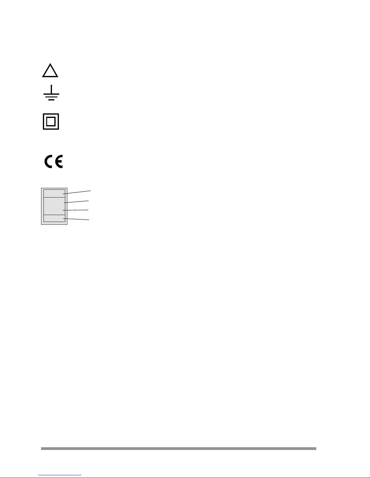
Meaning of symbols on the instrument
Warning concerning a point of danger
(Attention: observe documentation!)
Earth
Continuous doubled or reinforced insulation
CAT II Measurement category I I device
Indicates CE conformity
DKD calibration certificate (red label):
Repairs, Parts Replacement and Balancing
When the instrument is opened, voltage conducting parts may be exposed. The
instrument must be disconnected from the measuring circuit before repair,
replacement of parts or balancing. If repair or balancing of a live, open instrument
is required, this may only be carried out by trained personnel who are familiar
with the dangers involved.
Defects and Extraordinary Strains
If it may be assumed that the instrument can no longer be operated safely, it
must be removed from service and secured against unintentional use.
Safe operation can no longer be relied upon:
• If the instrument demonstrates visible damage
• If the instrument no longer functions
• After long periods of storage under unfavorable conditions, e.g. humidity,
dust, excessive temperature (see “Ambient Conditions” on page 25).
!
Consecutive number
Registration number
Date of calibration (year - month)
German calibration service – calibration laboratory
B0730
01-08
DKD-K19701
Page 7

GOSSEN METRAWATT GMBH 7
2 Initial Start-Up
Installing Batteries
Attention!
!
Disconnect the instrument from the measuring circuit at all poles before
opening the battery compartment!
➭ Fold the instrument closed.
➭ Insert a coin or a similar object into the slot between the housing and the
battery compartment cover and press down until the battery compartment
cover snaps open.
➭ Fold the instrument open as far as it will go and remove the battery
compartment cover.
➭ Insert two 1.5 V mignon batteries per IEC R6 or IEC LR6 into the battery
compartment, making sure they are poled in accordance with the symbols.
➭ Replace the battery compartment cover and press into position until it
audibly snaps into place.
Switching the Instrument On
➭ Set the toggle switch to the “ON” position.
Activation of the instrument is acknowledged with an acoustic signal.
If the instrument has been shut down automatically, press either the FUNC, DATA or
MAN key to switch the multimeter back on, or set the toggle switch to the “OFF”
position and leave it there for at least 5 s before returning it to the “ON” position.
Note!
☞
Electrical discharges and high frequency interference may lead to erroneous display values, and may disable the measuring sequence. Reset
the instrument by switching it off and then, after 5 s, back on again.
Switching the Instrument Off Manually
➭ Set the toggle switch to the “OFF” position and fold the instrument closed. The
battery is automatically disconnected when the multimeter is folded closed.
Automatic Shutdown (standby)
The instrument switches itself off automatically if the measured value remains
constant for a long period of time (maximum measured value fluctuation approx.
0.8% of the measuring range per minute, or 1° Celsius or 1° Fahrenheit per
minute), and if no keys are activated for a period of approximately 10 minutes.
Shutdown is acknowledged by a brief acoustic signal. Exception: continuous
operation mode.
Note!
☞
Electrical power is supplied to the processor even after the instrument
has been switched off automatically. A closed-circuit current of about
300 µA remains. The instrument is only disconnected from the batteries
after it has been switched off manually with the toggle switch or with the
instrument folded.
Page 8
8 GOSSEN METRAWATT GMBH
Disabling Automatic Shutdown
The instrument can be switched to “CONTINUOUS ON”.
➭ Press the FUNC key while switching the instrument on with the toggle switch
until an acoustic signal is generated. The “CONTINUOUS ON” function
is indicated at the display with the symbol.
3 Selecting Measuring Functions and Measuring Ranges
3.1 Automatic Measuring Range Selection
The multimeter is equipped with auto-ranging for all measuring ranges except for
temperature measurement, diode and continuity testing and the 15 A range.
Auto-ranging is always activated as soon as the instrument is switched on.
Depending upon the measured quantity, the device automatically selects the
measuring range which allows for best possible resolution.
The instrument automatically switches to the next highest or next lowest
measuring range for the following measured quantities:
1)
28 digits - 1 digit for switching from the 300 kHz to the 3 kHz range
3.2 Manual Measuring Range Selection – MAN/AUTO Key
Auto-ranging can be deactivated and ranges can be set manually in accordance
with the following table.
The manual mode is deactivated by pressing and holding the MAN/AUTO key for
about 1 s, by turning the rotary switch or by switching the instrument off and
back on again.
Measuring Ranges Resolution
Switching to the next
highest range occurs
at ±(... d + 1 d)
Switching to the next
lowest range occurs
1)
at ±(... d –1 d)
V~, V , mA , mA~, Ω,
Hz,30 nF … 3 mF,
3 ¾ 3 100 280
Key
MAN/AUTO
Function
Acknowledgement
Visual Acoustic
brief Manual mode active: utilized measuring range is fixed MAN 1 x
brief
Switching sequence for:
V: 300 mV → 3V→ 30 V → 300 V → 600 V → 300 mV → …
mA: 300 µA → 3mA→ 30 mA → 300 mA → 300 µA …
Ω:30MΩ→ 300 Ω→ 3kΩ→ 30 kΩ→ 300kΩ→ 3MΩ→
30 MΩ…
F: 30 nF → 300 nF → 3 µF → 30 µF → 300 µF →
3000 µF → 30 000 µF → 30 nF …
Hz: 300 Hz → 3kHz→ 300 kHz → 300 Hz …
: 3.000 → 30,00 → 300,0 → 3,000 …
MAN 1 x
long Return to automatic measuring range selection — 2 x
Page 9

GOSSEN METRAWATT GMBH 9
3.3 Quick Measurements
If you wish to perform quicker measurements than those possible with the automatic measuring range selection function, make sure to establish the appropriate
measuring range:
•by manual measuring range selection, i. e. by selecting the measuring range
with the best resolution, see chapter 3.2.
or
•via DATA function, see chapter 5. After the first measurement, the proper
measuring range will be automatically determined so that measurements are
performed more rapidly from the second measured value onwards.
With both functions, the established measuring range is maintained for the subsequent series mode measurments.
4Display (LCD)
4.1 Digital Display
The measured value appears at the digital display with decimal point and sign (+
or -). The selected unit of measure and the type of current are displayed as well.
A minus sign is displayed to the left of the value for the measurement of zerofrequency quantities if the positive pole of the measured quantity is applied to the
⊥ jack.
If the measuring range upper limit is exceeded for the following measured
quantities, “OL” (overload) is displayed:
V (DC), I (DC), Ω, Hz, V~ (AC), I~ (AC), 30 nF
… 3 mF: 3099 digits
30 mF: 30999 digits
The digital display is refreshed at different rates for the individual measured
quantities (see “Display Refresh Rates” on page 24.
4.2 Analog Display
The analog display with simulated pointer and dynamic response equivalent to
that of a moving-coil mechanism, is refreshed 20 times per second. This display
is especially advantageous for the observation of measured value fluctuations,
and during balancing.
The analog display is equipped with a polarity indicator. The scale is extended 5
segments into the negative range for the measurement of zero-frequency
quantities, allowing for precise observation of measured value fluctuation around
the zero point. If the measured value exceeds the display range, a triangle is first
display at the left, and polarity at the display is reversed approximately 0.7
seconds later. If the measuring range is exceeded (> 3099 digits, in
the 30 mF range: > 30999) a triangle is displayed at the right.
Scaling at the analog display is automatic, which is quite helpful for manual
measuring range selection.
Page 10

10 GOSSEN METRAWATT GMBH
5 Measured Value Storage – DATA / MIN-MAX Key
5.1 DATA (hold / compare)
Measured values can be automatically frozen at the display with the DATA (hold)
function. This is especially useful when full attention is required for contacting the
measuring point. After the measured value has been applied to the multimeter
and the “condition” indicated in the following table has been fulfilled, the measured value is frozen at the digital display and an acoustic signal is generated.
The test probes can then be removed from the measuring point, and the measured value can be read from the digital display. If the measured value is less
than the limit value shown in the table, the instrument is reactivated for a new
measurement with the DATA hold function.
If the new measured value deviates from the previous value by less than 10 digits, the acoustic signal sounds twice (DATA compare).
1)
Reactivation occurs if the indicated measured value limits are fallen short of.
2)
Double acoustic signal after the first measured value has been stored.
Thereafter, double acoustic signal only occurs if the currently frozen value deviates from the
first stored value by less than 10 digits.
3)
Exception: 10% at 300 Ω
The DATA function has no effect on the analog display, which continues to
indicate the current measured value. However, it must be observed that the
decimal place is fixed when the digital display is “frozen”.
The DATA function can be deactivated by pressing and holding the DATA key for
about 1 second, by turning the function selector switch or by switching the
instrument off and back on again.
Function
DATA
Key
DATA
Condition Reaction at Instrument
Measuring
Ranges
Measured Value
Limits
(digits)
Display
Acoustic
Signal
Measured
Value, Digital
DATA
Activate brief blinks 1 x
Hold
V, A, Ω, F, H z
, ,
> 3.3% of range
OL
3)
> 3.3%
3)
of range
is
displayed
is
displayed
1 x
2 x
2)
Reactivate
1)
V, A, Ω, F, H z
, ,
< 3.3% of range
OL
3)
< 3.3% 3)
of range
frozen
measured
value
blinks
Deactivate long
is
cleared
is
cleared
2 x
Page 11

GOSSEN METRAWATT GMBH 11
5.2 Storage of Minimum and Maximum Values “MIN/MAX” with Time Stamp
Minimum and maximum measured values which occur at the input of the measuring instrument after the MIN/MAX function has been activated can be saved
to memory. The most important application for this function is the determination
of minimum and maximum values during long-term observation of measured
quantities (same function as the slave pointer at an analog display).
The “MIN/MAX” function can be activated for all measuring ranges.
The MIN/MAX function has no effect on the analog display, which continues to
indicate the current measured value.
Apply the measured quantity to the instrument and select the measuring range
before activating the MIN/MAX function.
Measuring ranges can only be selected manually after the function has been
activated, and stored MIN/MAX values and time stamps are deleted in doing so.
The MIN/MAX function is deactivated by pressing and holding the DATA key for
about 1 second, by turning the function selector switch or by switching the
instrument off and back on again.
Function
MIN-MAX
Key
DATA
MIN and MAX
Measured Values /
Time Stamps
Reaction at Instrument
Display
Acoustic
Signal
Measured Value,
Digital
MIN MAX
1.
Activate and
Save
2 x brief are saved
current measured
value
MIN and MAX
blink
2 x
2.
Save and
Display
brief
Storage continues
in background,
new MIN and MAX
values and time
stamps are displayed
stored MIN value MIN 1 x
brief
time elapsed to
stored MIN value
MIN and h:mm:ss 1 x
brief MIN and hh:mm 1 x
brief stored MAX value MAX 1 x
brief
time elapsed to
stored MAX value
MAX and h:mm:ss 1 x
brief MAX and hh:mm 1 x
3.
Return to 1.
brief
same as 1.,
stored values are not
deleted
same as 1. same as 1. 1 x
Deactivate long are deleted is deleted is cleared 2 x
Page 12

12 GOSSEN METRAWATT GMBH
6 Voltage Measurement
➭ Set the rotary switch to either V (TRMS) or V , depending upon the
voltage to be measured.
➭ Connect the measurement cables as shown. The ⊥ jack must be grounded.
Note!
☞
An intermittent acoustic signal warns the operator if the measured value
exceeds the measuring range upper limit in the 600 V range.
Attention!
!
Make certain that neither of the current measuring ranges is selected
(“mA” or “A”) and that the measuring cables are connected to the right
“V” und “^” jacks when the multimeter is connected for voltage measurement! Both the operator and the instrument are in danger if the
breaking thresholds for the fuses are exceeded due to operator error!
Zero Balancing in the
300 mV Measuring Range
➭ Select the 300 mV
measuring range.
➭ Connect the measure-
ment cables to the instrument and connect the
free ends to one another.
➭ Briefly press the FUNC key.
The instrument acknowledges
zero balancing with an
acoustic signal, and “000
.0”
(±1 digit) and the ZERO
symbol appear at the LCD.
The voltage displayed at the
moment the key was pressed
is used as a reference value
(max. ±200 digits which
corresponds to 20 mV).
This value is automatically subtracted from all subsequently measured values.
➭ Zero balancing can be cleared:
– by pressing and holding the FUNC key,
after which clearing is acknowledged by
– a twice repeated acoustic signal,
by switching the instrument off.
– (+)~+ (–)
~
Page 13

GOSSEN METRAWATT GMBH 13
6.1 Transient Overvoltages
The multimeter is protected against transient voltages of up to 4 kV with front
and half times of up to 1.2 and 50 µs respectively. Due to the fact that powerful
overvoltages must be reckoned with during measurement, for example in power
systems, at transformers or motors, we recommend the use of our KS30 measuring adapter in such cases. It offers protection against transient overvoltages
of up to 6 kV with front and half times of up to 10 and 1000 µs respectively.
Continuous load capacity is equal to 1200 V
eff
. Additional measuring error
due to use of the KS30 measuring adapter amounts to approximately –2 %.
6.2 Measuring Voltages of Greater than 300 V
Voltages of greater than 300 V can be measured with a high-voltage measuring
probe, for example the HV3
1)
of the HV302) from GOSSEN METRAWATT GMBH.
The bonding terminal must be grounded in this case. Observe all applicable
safety precautions!
1)
HV3: 3 kV
2)
HV30: 30 kV for (DC) voltage only
7 Current Measurement
➭ First disconnect supply power from the measuring circuit or the power
consumer and discharge all capacitors, if any are present.
➭ Select range A with the rotary switch for currents of greater than 300 mA, or
range mA for currents of less than d 300 mA. Always start with measuring
range A when measuring current of an unknown magnitude.
➭ Select the current type which corresponds to the measured quantity by
briefly pressing the FUNC key. Each time the key is pressed, the instrument is
alternately switched back and forth between (DC) and ~ (AC), which is
acknowledged with an acoustic signal. The symbol for the selected current
type, (DC) or ~ (AC), appears at the LCD. Direct current ( ) is always
active immediately after the instrument is switched on, and after range
selection with the rotary switch.
➭ Connect the measuring instrument securely to the power consumer in
series as shown in the diagram (without transition resistor).
black
black
red
x1000
x100
Measuring voltages of greater than 300 V
with the HV3 high-voltage probe
Page 14

14 GOSSEN METRAWATT GMBH
Notes Concerning Current Measurement:
• The instrument may only
be used in power installations if the electrical
circuit is protected with
a fuse or a circuit
breaker with a rating of
up to 20 A, and if nominal voltage at the system does not exceed
240 V~ (AC) or
50 V (DC).
• Set up the measuring
circuit in a mechanically secure fashion
such that it cannot be
inadvertently interrupted. Use conductors with an adequate cross section
and connectors of
adequat e s ize in orde r
to prevent excessive warming.
• An intermittent acoustic signal warns the operator if the measured value
exceeds the measuring range upper limit in the 300 mA and 15 A ranges.
• All current measuring ranges up to 300 mA are protected with a FF1A/380V
AC fuse, and the 300 mA range is protected with a fuse (T2.5A/250V) in
combination with damping diodes. The breaking capacity of the slow-blow
fuse is equal to 10 kA at a nominal voltage of 380 V AC with a resistive load.
• The 15 A current measuring range is protected with a resettable miniature
circuit breaker: 15A/240V AC / 50V DC.In order to conform to the CAT
requirements, an additional slow-blowing fuse link (T16A/500V) has been fitted in series with the miniature circuit breaker which can only be replaced by
service personnel once it is tripped.
• If a fuse or circuit breaker in the active current measuring range is tripped,
FUSE appears at the digital display, and an acoustic signal is generated
simultaneously.
• Eliminate the cause of overload after the fuse or breaker is tripped before
placing the instrument back into service!
• Fuse replacement is described in chapter 15.2, on page 26.
Note!
☞
Motors with high starting current cause tripping of the circuit breaker,
except for measurement with clip-on ammeters.
– (+) / ~ + (–) / ~
Page 15

GOSSEN METRAWATT GMBH 15
7.1 Current Measurement with Current Transformers with Voltage Output
If a current sensor is connected to the multimeter, all current values are displayed
correctly in consideration of the transformer ratio. This presupposes that the current transformer is equipped with the required sensitivity, and that the
appropriate ratio is selected before measurement is performed.
➭ Turn the rotary switch to the position
.
➭ Select a current type, ~ (AC) or (DC), by pressing the FUNC key.
➭ Simultaneously press the FUNC and the MAN/AUTO keys. The currently
selected transformation ratio is displayed. The transformer ratio can be
changed by pressing the MAN or the DATA key, or the currently selected value
can be retained by pressing the FUNC key.
➭ Connect the (clip-on) current transformer or the clip-on current sensor to the
and the ⊥ jacks.
Attention!
!
If the secondary side of the current transformer with voltage output
remains open during operation, e.g. if cables are defective or have not
been connected, or due to a blown device fuse or incorrect
connection, dangerous voltages may occur at the terminals.
Maximum allowable operating voltage is equal to the nominal voltage of the
current transformer. Additional error caused by the clip-on ammeter must be
taken into consideration.
transformer ratio
max. measuring range
switch clip-on
current transf.
LCD
multimeter
A A~
1 mV/ 1 mA 1:1 mA
1 mV/ 10 mA 1:10 mA
1 mV/ 100 mA (Z13B) 60 A 40 A 10 mV/A 1:100 mA
1 mV/ 1 A (Z13B) 600 A 400 A 1mV/A 1:1 A
V/~
M
I(A)
Z13B
Page 16

16 GOSSEN METRAWATT GMBH
8 Resistance Measurement
➭ Set the rotary switch to the Ω
position. Overload is indicated
if no device under test has been
connected: “0.L MΩ”.
➭ Before connecting the device under
test, make sure that it is voltagefree. Interference voltages distort
measurement results! Perform a
voltage test first if required.
➭ Connect the device under test as
shown in the diagram.
Zero Balancing in the 300 Ω and 3 kΩ Measuring Ranges
Resistance at cables, as well as contact resistances, can be eliminated for the
measurement of low-resistance values in the 300 Ω and 3 kΩ ranges by means
of zero balancing:
➭ Connect the measurement cables to the instrument and connect the free
ends to one another (short circuit the test probes).
➭ Briefly press the FUNC key.
The instrument acknowledges zero balancing with an acoustic signal, and
“000
.0 Ω” or “0.000 kΩ” and the ZERO symbol appear at the LCD.
Resistance measured at the moment the key is pressed is used as a
reference value (max. 200 digits). This value is automatically subtracted from
all subsequently measured values.
➭ Zero balancing can be cleared:
– by pressing and holding the FUNC key, after which clearing is acknowledged
by a twice repeated acoustic signal,
– by switching the instrument off.
9 Continuity Testing
With the “acoustic signal” function activated, and exclusively in the 0 to 310 Ω
measuring range, the instrument generates a continuous acoustic tone for
measured resistance within a range of 0 to approximately 10 Ω.
➭ Turn the selector switch to the position. The and Ω symbols appear at
the LCD.
➭ Connect the measurement cables to the device under test.
Note!
☞
Continuity testing is very fast (< 50 ms) and is suitable for locating
connections with poor contact (e.g. due to vibration) in automotive
service applications.
R
x
Voltage Drop
Page 17

GOSSEN METRAWATT GMBH 17
10 Diode Testing
➭ Turn the selector switch to the position. Overload is indicated if no
device under test has been connected: “.0L V”.
➭ Make sure that the device under test is voltage-free. Interference voltages
distort measurement results! Perform a voltage test first if required.
➭ Connect the device under test as shown in the diagram.
Conducting Direction or Short-Circuiting
Conducting state voltage is displayed in volts at the measuring instrument. As
long as voltage drop does not exceed the maximum allowed display value of
1.8 V, several elements or reference diodes with minimal reference voltage can
be connected in series for testing. If “.0L” appears at the display, either the circuit
is interrupted or conducting state voltage is greater than 1.8 V.
Blocking Direction or Interruption
“.0L” is displayed at the instrument. If a value of less than 1.8 V is displayed, this
generally indicates that the diode’s blocking direction is defective.
Note!
☞
Resistors and semiconductor paths which have been connected in
parallel to the diode distort measurement results!
Conducting
Direction
Blocking
Direction
Page 18

18 GOSSEN METRAWATT GMBH
11 Capacitance Measurement
➭ Make sure that the device
under test is voltage-free.
Interference voltages distort
measurement results!
➭ Turn the rotary switch to the
“F” position.
➭ Connect the (discharged!)
device under test to the ⊥
and V jacks with the
measurement cables.
Zero Balancing in the 30 nF Measuring Range
Intrinsic capacitance at the measuring instrument and cables can be eliminated
for the measurement of small capacitance values in the 30 nF range by means of
zero balancing:
➭ Connect the measurement cables to the measuring instrument without a
device under test.
➭ Briefly press the FUNC key.
The instrument acknowledges zero balancing with an acoustic signal and
“00
.00 ” and the ZERO symbol appear at the LCD. Capacitance measured
at the moment the key is pressed is used as a reference value (max.
200 digits). This value is automatically subtracted from all subsequently
measured values.
➭ Zero balancing can be cleared:
– by pressing and holding the FUNC key, after which clearing is acknowledged
by a twice repeated acoustic signal,
– by switching the instrument off.
12 Frequency Measurement
➭ Turn the rotary switch to the Hz position.
➭ Apply the measured quantity as described under voltage measurement.
➭ Smallest measurable frequencies and maximum allowable voltages are
listed in chapter 14, “Characteristic Values”.
+
–
Page 19

GOSSEN METRAWATT GMBH 19
13 Temperature Measurement with Pt100 and Pt1000
➭ Turn the rotary switch to
the “ ” position.
➭ Select either °C or °F by
pressing the FUNC key.
➭ Connect the P
t sensor to
the ⊥ and V jacks. The
instrument automatically
recognizes type of
connected sensor (Pt100
or Pt1000), and displays
measured temperature in
the selected unit of
measure.
Note!
☞
The characteristic cable resistance for the temperature sensors which
are available as accessories is automatically taken into consideration for
this measurement.
Temperature Measurement
with Compensation for Sensor Cable Resistances from 0.1 Ω to 50 Ω
Sensor cable resistances with values other than100 mΩ can be compensated
for values of up to 50 Ω as follows:
➭ Briefly press the FUNC and the MAN/AUTO keys simultaneously. The currently
selected cable resistance is displayed. This value can be increased with the
DATA key, or reduced with the MAN/AUTO key. Each time one of these keys is
briefly activated, the value is changed by 10 digits (0.1 Ω). The value can be
changed by means of rapid scrolling by pressing and holding the key.
➭ Switch back to temperature measurement by briefly acknowledging with the
FUNC key.
The new cable resistance value is retained, even after the instrument has been
switched off.
Note!
☞
The default setting is Pt100 with a cable resistance of 0.1 Ω.
Z3409
Page 20

20 GOSSEN METRAWATT GMBH
14 Characteristic Values
1)
Up to max. 1.8 V diode voltage, “OL” (overload) is displayed for higher values.
2)
Smallest measurable frequency for sinusoidal measuring signal symmetric to zero point.
3)
Exception: Pt1000: – 100.0 °C
4)
corresponds to 600 V CAT I
Key: d = digit(s), rdg. = reading, MUL = measuring range upper limit
Measuring
Function
Measuring Range
Resolution at MUL Input Impedance
3 000
~
V
300 mV 100 µV > 20 MΩ 5MΩ //<50pF
3V 1mV 11MΩ 5MΩ //<50pF
30 V 10 mV 10 MΩ 5MΩ //<50pF
300 V 100 mV 10 MΩ 5MΩ //<50pF
600 V
4)
1 V 10 MΩ 5MΩ //<50pF
Approximate Voltage Drop at MUL
A
300 µA 100 nA 160 mV
3mA 1µA 160 mV
30 mA 10 µA 200 mV
300 mA 100 µA 300 mV
15 A 10 mA 700 mV
Open-Circuit Voltage
Measuring Current
at MUL
Ω
300 Ω 100 mΩ 0.6 V max. 250 µA
3kΩ 1 Ω 0.6 V max. 45 µA
30 kΩ 10 Ω 0.6 V max. 4.5 µA
300 kΩ 100 Ω 0.6 V max. 1.5 µA
3MΩ 1kΩ 0.6 V max. 150 nA
30 MΩ 10 kΩ 0.6 V max. 15 nA
300 Ω 0.1 Ω max. 3 V max. 1.2 mA
3V
1)
1 mV max. 3 V max. 1.2 mA
Discharge
Resistance
U
0 max
F
30 nF 10 pF 10 MΩ 3V
300 nF 100 pF 1 MΩ 3V
3 µF 1 nF 100 kΩ 3V
30 µF10nF11kΩ 3V
300 µF 100 nF 2 kΩ 3V
3000 µF1µF2kΩ 3V
30000 µF1µF2kΩ 3V
f
min
2)
Power Limit
Hz
300.0 Hz 0.1 Hz 1 Hz
3 x 10⁶ V x Hz3.000 kHz 1 Hz 1 Hz
100.0 kHz 100 Hz 1 Hz
°C/°F
Pt100/
Pt1000
– 150.03)...
+100.0 °C
0.1 °C
+ 100.0 ...
+850.0 °C
Page 21

GOSSEN METRAWATT GMBH 21
1)
At 0 ° to + 40 °C
2)
Values < 5 digits are suppressed, intrinsic error values valid as of 100 digits except for 7).
15 (20) … 45 ... 65 Hz … 1 kHz sine, see page 22 for influences.
3)
15 A – 5 min
4)
If “zero balancing” function is active, ZERO appears at display.
5)
Plus sensor error
6)
Sinusoidal input voltage at least 3 kHz > 50 mV, 3 kHz at least 100 kHz > 200 mV
7)
Indicated intrinsic error values valid for 3 to 100% of the mV measuring range
Measuring
Range
Intrinsic Error for Max. Resolution
under Reference Conditions
Overload Capacity
1)
±(… % rdg. + … d) ±(… % rdg. + … d)
~
2)
Value Duration
300 mV 0.5 + 2
4)
0.5+5
7)
600 V
(DC)
~ (AC)
eff sine
continuous
3 V 0.5+2 0.5+5
30 V 0.5+2 0.5+5
300 V 0.5+2 0.5+5
600 V 0.5 + 2 0.5 + 5 600 V CAT I
~
2)
300 µA 0.5+2 0.5+5
0.36 A
continuous
3 mA 0.5+2 0.5+5
30 mA 0.5+2 0.5+5
300 mA 0.5+2 0.5+5
15 A 0.5 + 2 0.75 + 5 10 A
3)
300 Ω 0.5+2
4)
300 V
(DC)
~ (AC)
eff
sine
max. 10 s
3kΩ 0.5+2
4)
30 kΩ 0.5+2
300 kΩ 0.5+2
3MΩ 0.5+2
30 MΩ 2+2
0.5+3
3 V 0.5 + 3
30 nF 1 + 6
4)
300 V
(DC)
~ (AC)
eff
sine
max. 10 s
300 nF 1 + 6
3 µF 1 + 6
30 µF 1 + 6
300 µF 5 + 6
3 mF 5 + 6
30 mF 5 + 60
Max. Measuring Voltage
300.00 Hz
0.1 + 2
6)
300 V
300 V continuous
3.0000 kHz 300 V
<30kHz 100V
>30kHz 30V
Pt 100/
Pt1000
–150.0 ... + 100.0 °C 1 K + 3
5)
300 V (DC) /
~ (AC)
eff sine
max. 10 s
+100.0 ... + 850.0 °C 1% + 3
5)
Page 22

22 GOSSEN METRAWATT GMBH
Influence Quantities and Influence Error
1)
With zero balancing
2)
Indicated error applies as of a display value of 10% of the measuring range.
Influence
Quantity
Sphere of
Influence
Measured Quantity /
Measuring Range 1)
Influence Error
(… % + … d) / 10 K
Temperature
0 °C …
+21 °C
and
+25 °C …
+40 °C
V 0.2 + 1
V ~ 0.4 + 1
300 µA … 300 mA
+ ~
0.5 + 1
3 A / 10 A + ~ 1 + 1
300 Ω … 300 kΩ 0.2 + 1
3MΩ 0.2 + 1
30 MΩ 1 + 1
30 nF … 30 µF 0.5 + 1
Hz 0.5 + 1
°C (Pt100) 0.5 + 1
Influence
Quantity
Sphere of
Influence
(max. resolution)
Frequency
Intrinsic Error 2)
± (… % rdg. + … d)
Frequency
V~
(AC)
300.0 mV
3.000 V
30.00 V
300.0 V
> 15 Hz ... 45 Hz 2 + 5
> 65 Hz ... 1 kHz 1 + 5
Influence
Quantity
Sphere of
Influence
(max. resolution)
Frequency
Intrinsic Error
2)
±(… % rdg. + … d)
Frequency
I~
(AC)
300.0 µA
...
15.00 A
> 15 Hz ... 45 Hz
1 + 5
> 65 Hz ... 1 kHz
Page 23

GOSSEN METRAWATT GMBH 23
1)
Except for sinusoidal waveshape
Influence
Quantity
Sphere of
Influence
Measured Quantity /
Measuring Range
Influence Error
1)
Measured
Quantity
Waveshape
3)
Crest
factor
CF
1 … 2
V ~, A ~
± 1% rdg.
>2 ...4 ± 5% rdg.
>4 ...5 ± 7% rdg.
Influence
Quantity
Sphere of
Influence
Measured Quantity /
Measuring Range
Influence Error
Relative
Humidity
75%
3 days
device off
V, A , Ω
F, H z
°C
1 x intrinsic error
Influence
Quantity
Sphere of Influence
Measuring
Range
Damping
Common-
Mode
Interference
Voltage
interference quantity max. 300 V V > 90 dB
interference quantity max. 300 V ~
50 Hz, 60 Hz sine
300 mV ...
30 V ~
> 60 dB
300 V ~ > 60 dB
Series-Mode
Interference
Voltage
interference quantity V ~
nom. value, respective measuring range,
max. 300 V ~, 50 Hz, 60 Hz sine
V > 40 dB
interference quantity max. 300 V
nom. value, respective measuring range
V ~ > 50 dB
1
2
3
4
5
CF
0
Voltage and Current
Measurement
Allowable crest factor CF for the
periodic quantity to be measured
depends upon the displayed value:
Digits
1000 2000 3000
Page 24

24 GOSSEN METRAWATT GMBH
Reference Conditions
Ambient Temperature +23 °C ±3K
Relative Humidity 40
… 60%
Measured Qty. Frequency 45
… 65 Hz
Measured Qty. Waveshape sinusoidal
Battery Voltage 3 V ±0.1 V
Response Time (after manual range selection)
Display
LCD window (95 mm x 40 mm) with analog and digital display, including display
of unit of measure, current type and various special functions
Analog:
Display LCD scale with pointer
Scale length 80 mm for V and A ;
67 mm for all other ranges
Scaling 5
… 0 … ± 30 with 35 scale graduations for ,
0 ... 30 with 30 scale graduations for all other ranges
Polarity Display with automatic switching
Overload Display triangle appears
Sampling Rate 20 measurements per second
Digital:
Display/Char. Height 7 segment characters / 20 mm
Number of Places 3¾-place 3100 steps
Overload Display “0L” appears
Polarity Display “–” is displayed if plus pole is connected to ⊥ jack
Sampling Rate 2 measurements per second
Display Refresh Rates
V (DC), V~ (AC), A, Ω, ,
°C (Pt100, Pt1000) twice per second
Hz once per second
Measured Quantity /
Measuring Range
Digital Display
Response Time
Measured Quantity
Jump Function
V , V ~,
A, A~
1.5 s
from 0 to 80%
of the measuring range upper limit
300 Ω … 3MΩ 2s
from ∞ to 50%
of the measuring range upper limit
30 MΩ 5s
Continuity < 50 ms
1.5 s
30 nF … 300 µF max. 2 s
from 0 to 50%
of the measuring range upper limit
3 000 µF max. 7 s
30 000 µF max. 14 s
>10 Hz max. 1.5 s
°C max. 3 s
Page 25

GOSSEN METRAWATT GMBH 25
Power Supply
Batteries 2 ea. 1.5 V mignon cell
alkaline-manganese per IEC LR6
or zinc-carbon per IEC R6
Service Life with alkaline-manganese batteries: approx. 100 hours
with zinc-carbon batteries: approx. 50 hours
Battery Test symbol is displayed automatically if battery voltage
drops to below approximately 2.3 V.
Battery Saving Circuit
The instrument is switched off automatically if the measured value remains
unchanged for a period of approximately 10 minutes, and if none of the control
elements are operated during this period. Automatic shutdown can be disabled.
Fuses
Range up to 300 mA FFF1A/380VAC, 5 mm x 20 mm
Switching capacity 10 kA at 380 V AC and ohmic load;
protects, in combination with power diodes, all current
measuring ranges up to 300 mA
15 A range
– Resettable 15A/240VAC/50VDC miniature circuit breaker,
– additionally, a fuse link has been joint in series with
the m.c.b.: T16A/500VAC, 6.3 mm x 32 mm
Switching capacity 1.5 kA at 500 V AC and ohmic load
Electrical Safety
Safety Class II per IEC/EN 61010-1:2001/VDE 0411-1:2002
Measurement Category
II
Operating Voltage 300 V
Contamination Level 2
Test Voltage 2.3 kV~ per IEC/EN 61010-1:2001/VDE 0411-1:2002
Electromagnetic Compatibility (EMC)
Interference Emission EN 61 326:2002 Class B
Interference Immunity EN 61326:2002
IEC 61000-4-2:1995/A1:1998, Feature A
8 kV atmospheric discharge
4 kV contact discharge
IEC 61000-4-3:1995/A1:1998, Feature B; 3 V/m
Ambient Conditions
Operating Temp. − 10 °C
… +50 °C
Storage Temperature −25 °C
… +70 °C (without batteries)
Relative Humidity max. 75%, no condensation allowed
Elevation to 2000 m
Deployment indoors, outdoors: only within the specified
ambient conditions
Page 26

26 GOSSEN METRAWATT GMBH
Mechanical Design
Protection housing: IP 40, connector jacks: IP 20
Dimensions 146 mm x 118 mm x 44 mm
Weight approx. 450 gr. with batteries
15 Maintenance
Attention!
!
Disconnect the instrument from the measuring circuit before opening to
replace batteries or fuses!
15.1 Batteries
Make sure that no battery leakage has occurred before placing your instrument
into service for the first time, or after long periods of storage. Repeat this
inspection on a regular basis thereafter.
If battery leakage has occurred, clean the electrolyte from the device completely
and carefully with a dampened cloth and install new batteries before placing the
instrument back into service.
If the symbol appears at the display, replace the batteries as soon as possible.
The instrument requires two 1.5 V batteries in accordance with IEC R 6 or
IEC LR 6.
Replacing the Batteries
Attention!
!
Disconnect the instrument from the measuring circuit at all poles before
opening the battery compartment!
➭ Fold the instrument closed.
➭ Insert a coin or a similar object into the slot between the housing and the
battery compartment cover and press down until the battery compartment
cover snaps open.
➭ Fold the instrument open as far as it will go and remove the battery
compartment cover.
➭ Insert two 1.5 V mignon batteries per IEC R6 or IEC LR6 into the battery
compartment, making sure they are poled in accordance with the symbols.
➭ Replace the battery compartment cover and press into position until it
audibly snaps into place.
➭ Please dispose of depleted batteries in an environmentally sound fashion!
15.2 Fuses
Eliminate the cause of overload after a fuse or breaker is tripped before placing
the instrument back into service!
Page 27

GOSSEN METRAWATT GMBH 27
mA Range
If the FF1A/380V AC fuse link for the active mA current measuring range is
tripped, FUSE appears at the digital display and an acoustic signal is generated
simultaneously.
Replacing Fuses for mA Ranges
➭ Open the instrument as described for battery replacement.
➭ Remove the blown fuse, which is situated under the batteries, e.g. with the
help of a test probe or a similar object, and replace it with a new fuse.
Attention!
!
Only fuses with the specified characteristics may be used (see chapter
14, “Characteristic Values”)! The use of fuses with other tripping characteristics, current ratings or breaking capacities represents a hazard
for damping diodes, resistors and other device components. The use
of repaired fuses and short-circuiting of the fuse holder are prohibited.
15 A Range
A humming sound originating from the 15 A circuit breaker is normal when
measuring high value alternating current.
If the miniature 15 A circuit breaker for the active current measuring range is
tripped, FUSE appears at the digital display and an acoustic signal is generated
simultaneously. Make sure that the red pin is popped out in the tripped condition,
i.e. that no adhesion or fusion has taken place. Short circuit the Ω and 15 A jacks
with the selector switch set to the continuity test position, and “0L” must appear
at the display.
Attention!
!
Inspect the measuring circuit and eliminate the cause of overload
before activating the reset button at the miniature circuit breaker.
15.3 Housing
No special maintenance is required for the housing. Keep outside surfaces clean.
Use a slightly dampened cloth for cleaning. Avoid the use of cleansers, abrasives
or solvents.
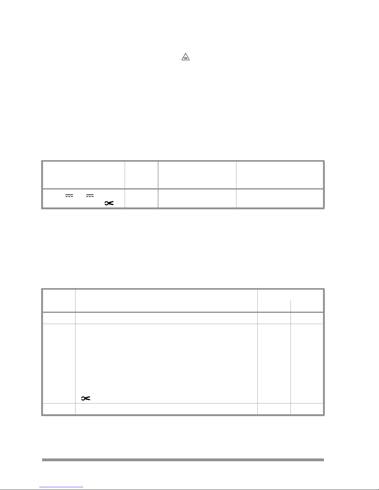
16 Multimeter Messages
Message Function Significance
FUSE Current measurement Blown fuse or tripped miniature circuit breaker
In all operating modes Battery voltage less than 2.3 V
OL In all measuring modes Indicates overload
Page 28

Edited in Germany • Subject to change without notice • A pdf version can be found on the internet
GOSSEN METRAWATT GMBH
Thomas-Mann-Str. 16-20
90471 Nürnberg • Germany
Phone+49-(0)-911-8602-0
Fax +49-(0)-911-8602-669
E-Mail info@gossenmetrawatt.com
www.gossenmetrawatt.com
17 Repair and Replacement Parts Service
DKD Calibration Lab* and Rental Instrument Service
When you need service, please contact:
GOSSEN METRAWATT GMBH
Service-Center
Thomas-Mann-Str. 20
90471 Nürnberg • Germany
Phone +49-(0)-911-8602-0
Fax +49-(0)-911-8602-253
E-Mail service@gossenmetrawatt.com
This address is only valid in Germany.
Please contact our representatives or subsidiaries for service in other countries.
* Calibration Laboratory for Electrical Quantities
DKD– K–19701 accredited per DIN EN ISO/IEC 17025
Accredited measured quantities: direct voltage, direct current values, DC
resistance, alternating voltage, alternating current values, AC active power, AC
apparent power, DC power, capacitance and frequency
18 Product Support
When you need support, please contact:
GOSSEN METRAWATT GMBH
Product Support Hotline
Phone +49-(0)-911-8602-112
Fax +49-(0)-911-8602-709
E-Mail support@gossenmetrawatt.com
DKD Calibration Certificate Reprints
If you order a DKD calibration certificate reprint for your instrument, please
provide us with the reference numbers indicated in the upper and lower most
fields of the calibration mark. We do not need the instrument’s serial number.
 Loading...