

Page 1
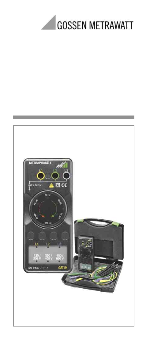
Operating Instructions
METRAPHASE 1
Phase Sequence Indicator
3-348-991-37
7/12.04
Page 2
600 V CAT IV
L3
L1
L2
1
2
3
L3
4
L2
L1
120/
230/
400V
400/
690V
5
208V
EN 61557 / 1 + 7
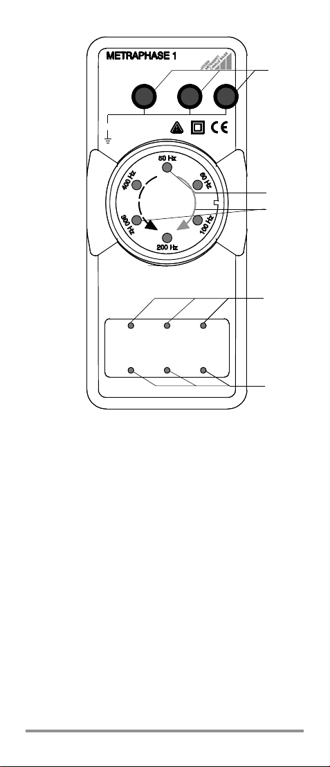
(1) Connector sockets for phases L1 ... L3
(2) Rotation LEDs for frequency display and direction of
phase rotation
(3) Direction of Phase Rotation and Frequency
Green arrow: clockwise rotation;
indicates correct phase sequence
Illuminated green LEDs rotate clockwise.
Frequency:
Indicated by brief, red illumination of corresp. LED.
Dashed red arrow: counterclockwise rotation;
indicates incorrect phase sequence
Illuminated red LEDs rotate counterclockwise.
Frequency:
Indicated by brief, green illumination of corresponding
LED.
(4) Phase LEDs, indicate voltage at L1 ... L3
(5) Voltage value LEDs, indicate value of line-to-line voltage
2 GOSSEN METRAWATT GMBH
Page 3

Tab le o f C o n t e n t s
Page
1 Safety Precautions .......................................................... 3
2 General Description ......................................................... 5
3 Initial Start-Up ................................................................. 5
4 Operation ......................................................................... 6
4.1 Voltage Display .................................................................. 6
4.2 3-Pole Connection ............................................................. 6
4.3 2-Pole Connection ............................................................ 7
5 Characteristic Values, Phase Sequence Indicator ........... 8
6 Maintenance ................................................................. 10
6.1 Batteries ......................................................................... 10
6.2 Housing .......................................................................... 10
7 Accessories (not included as standard equipment) ...... 11
8 Repair and Replacement Parts Service
DKD Calibration Lab
and Rental Instrument Service ...................................... 12
9 Product Support ............................................................ 12
1 Safety Precautions
General
This instrument fulfills the requirements of the applicable
European and national EC guidelines. We confirm this with
the CE marking. The relevant declaration of conformity can
be obtained from GOSSEN METRAWATT GMBH.
The phase sequence indicator has been manufactured and
tested in accordance with safety regulations IEC 61 010-1 /
DIN EN 61010-1 / VDE 0411-1.
When used for its intended purpose, safety of the operator,
as well as that of the instrument, is assured. Their safety is
however not guaranteed if the instrument is used improperly or handled carelessly.
In order to maintain flawless technical safety conditions,
and to assure safe use, it is imperative that you read the
operating instructions thoroughly and carefully before placing
your instrument into service, and that you follow all instructions
contained therein.
Repair and Parts Replacement
When the instrument is opened, voltage conducting parts
may be exposed. The instrument must be disconnected
from the measuring circuit or the device under test before
maintenance or the replacement of parts.
GOSSEN METRAWATT GMBH 3
GB
Page 4
The following safety precautions must be observed:
• The instrument may only be operated by persons who
are capable of recognizing contact hazards and taking
the appropriate safety precautions. Contact hazards
exist anywhere, where voltages of greater than 30 V
r.m.s. may occur.
• Avoid working alone when taking measurements
which involve contact hazards. Be certain that a
second person is present.
• Make certain that the measurement cables are in
flawless condition, and that they do not suffer from
damage to the conductors or their insulation. This
applies to test probes and alligator clips as well.
• No measurements may be made with this instrument
in electrical circuits with corona discharge
(high-voltage).
• Measurements under moist ambient conditions are not
permitted, nor are their results reliable.
• Use the recommended batteries.
• The instrument is not a voltmeter in the usual sense of
the word: it only reads out voltages within the indicated
ranges.
Errors and Extraordinary Strains
If it may be assumed that the instrument can no longer be
operated safely, it must be removed from service and
secured against further use.
Safe operation can no longer be relied upon,
• if the instrument demonstrates visible damage,
• if the instrument no longer functions.
Meanings of Symbols on the instrument
Warning concerning a point of danger
!
(Attention: observe documentation)
Earth
Continuous, double or reinforced
insulation
Indicates EU conformity
CAT IV The maximum allowable voltage between any given
connector jack (1) and earth is equal to 600 V,
category IV.
4 GOSSEN METRAWATT GMBH
Page 5

2 General Description
The instrument provides for the following measurement
and test functions:
• Phase sequence indicator
• Voltage display
• Frequency display
3 Initial Start-Up
Batteries
The phase sequence indicator is delivered with 4 mignon
cells installed and is ready for use. Before initial start-up,
please refer to chapter 6.1 “Batteries”.
Battery Test
If none of the LEDs light up after a voltage has been
applied, or if they are only faintly illuminated, the batteries
must be replaced.
Automatic Activation
The instrument is activated automatically as soon as a
voltage of at least 100 V is applied to any 2 measurement
sockets.
Automatic Shut-Down
The instrument is shut down automatically when zero
voltage is applied in order to extend battery service life.
GB
GOSSEN METRAWATT GMBH 5
Page 6

4Operation
4.1 Voltage Display
Voltage is displayed by means of 3 red LEDs (5), each of
which indicates a different nominal line voltage. The highest
voltage which occurs between two phases is always
displayed. Voltage is displayed for the following nominal
values: 120 V/208 V, 230 V/400 V und 400 V/690 V.
Missing or Non-Connected Phase
If one of the phases has not been connected to the phase
sequence indicator, or if one phase has not been wired, its
potential at artificial neutral is too small and the corresponding phase LED does not light up. However, the voltage value
LED which corresponds to line-to-line voltage is illuminated.
Exception: If no phase has been connected to terminal L1,
the voltage value LED displays the next lowest voltage
because the instrument is no longer provided with an internal reference point.
Attention!
!
The L1 jack at the METRAPHASE 1
must always be contacted first, in order
to avoid erroneous measurements.
4.2 3-Pole Connection
Symmetrical Clockwise Rotation
When a symmetrical, clockwise phase sequence is measured, phase LEDs L1, L2 and L3 are continuously illuminated
and a green point of light (rotation LED) rotates around the
display dial in the clockwise direction (at approx. 30 RPM).
Symmetrical Counterclockwise Rotation
Phase LEDs L1, L2 and L3 are also continuously illuminated for a symmetrical, counterclockwise phase
sequence, but the color and the direction of the rotating
point of light are changed: it rotates in the counterclockwise direction and is illuminated red.
Frequency Display
The appropriate frequency LED lights up briefly in red for a
clockwise phase sequence at the moment the rotating point
of light passes the corresponding position. The frequency
LED lights up green for a counterclockwise phase sequence.
Devices Connected to N or PE
If one of the devices has been connected to N or PE with an
asymmetrical phase sequence the phase LED for the incorrectly connected phase does not light up. Phase sequence
direction is indicated in the same way as it is for symmetrical
clockwise or counterclockwise phase sequences.
Wiring Incorrect
If wiring is incorrect, e.g. 2 x L1, ambiguous displays are
likely to occur.
6 GOSSEN METRAWATT GMBH
Page 7

4.3 2-Pole Connection
ABC
The phase sequence indicator also allows for the
determination of phase sequence direction with only
2 connector cables, as long as a line frequency of 50 or
60 Hz prevails:
➭ First connect terminal L1 to phase L1, and terminal L2
to phase L2 (see figure A).
Phase LEDs L1 and L2, as well as the corresponding
voltage value LED, light up red. The two LEDs for 100
and 400 Hz are also illuminated, which indicates that
the instrument has synchronized itself to phases L1
and L2.
➭ Disconnect phase L2 from terminal L2 (see figure B).
The two LEDs for 50 and 200 Hz light up during this
intermediate stage.
➭ Now connect phase L3 to terminal L2 (see figure C).
Phase LEDs L1 and L3 light up red. L2 is generated
internally. Phase sequence direction and line voltage
value are displayed.
Note!
☞
Approximately 2 seconds are allowed for changing
over from L2 to L3. If this time period is exceeded,
the instrument is no longer able to maintain synchronization with the electrical system. This error is
indicated by means of simultaneous illumination of
the LEDs for 60, 100, 300 and 400 Hz. The LEDs
for 100 und 400 Hz are then illuminated in order to
indicate that 2-pole measurement has been
resumed. The same display occurs if phase L2 is
inadvertently reconnected instead of changing to
phase L3.
GB
GOSSEN METRAWATT GMBH 7
Page 8

5 Characteristic Values, Phase Sequence Indicator
Line Frequency
Nominal
Frequency
50 Hz
60 Hz 58.3 ... 61.0 Hz 58.1 ... 61.2 Hz
100 Hz 97.7 ... 102.8 Hz 97.5 ... 103 Hz
200 Hz 195.4 ... 205.6 Hz 195.2 ... 205.8 Hz
300 Hz 299 ... 303.4 Hz 298.8 ... 303.6 Hz
400 Hz
1)
< 50 Hz/> 400 Hz: both LEDs active
Total frequency range 15 ... 410 Hz
Total line voltage
3 Phase ~Line Voltage
Nominal Line Voltage
Phase Sequence Direction
Direction
Clockwise L1 - L2 - L3
Counter-
clockwise
Asymmetrical Lx - N/PE - Lx
Phase Missing Lx - X - Lx
Display Range Tolerance Band Display
1)
49.4 ... 50.7 Hz 49.2 ... 50.9 Hz
— 51.1 ... 57.9 Hz 50.9 ... 58.1 Hz
— 61.4 ... 97.3 Hz 61.2 ... 97.5 Hz
— 103.2 ... 195 Hz 103 ... 195.2 Hz
— 206 ... 298.6 Hz 205.8 ... 298.8 Hz
— 303.8 ... 395.3 Hz 303.6 ... 395.5 Hz
1)
395.7 ... 405.8 Hz 395.5 ... 406 Hz
LED is active
50 Hz and 60 Hz
LEDs are active
LED is active
60 Hz and 100 Hz
LEDs are active
LED is active
100 Hz and 200 Hz
LEDs are active
LED is active
200 Hz and 300 Hz
LEDs are active
LED is active
300 Hz and 400 Hz
LEDs are active
LED is active
100 ... 690 V
Phase
Display Range
L-L Voltage
Display at
Phase LEDs
L1 L2 L3
light up
connection with
N/PE
not indicated
missing phase
does not light up,
the other 2 do
light up
LED Display
120/208V 180 ... 300 V 104 ... 173 V
230/400V 360 ... 470 V 208 ... 271 V
400/690V 530 ... 800 V 306 ... 462 V
Phase
Sequence
L3 - L2 - L1 L1 L2 L3 light up
Corresponding
L-N Voltage
Display at Rotation LEDs
green LED rotates
in clockwise direction
red LED rotates in
counterclockwise direction
green or red LED rotates
clockwise or
counterclockwise
depending upon connection
50 Hz
60 Hz
100 Hz
200 Hz
300 Hz
400 Hz
—
8 GOSSEN METRAWATT GMBH
Page 9

Reference Conditions
Ambient Temperature
Relative Humidity
Battery Voltage
Line Voltage
Line Frequency
+23°C ±2K
40 ... 60%
4.5 V ±0.25 V
230/400 V ±0.5%
50 Hz ±0.1 Hz
Line Voltage
Waveshape
sine, deviation between effective
and rectified value < 1%
Ambient Conditions
Storage Temperature
Operating Temperature
Relative Humidity
Altitude
–25 °C ... +75 °C
–10 °C ... +50 °C
max. 75%, no condensation
to 2000 m
Power Supply
Battery
4 mignon cells, alkaline-
manganese per IEC LR6
(4 x AA-Size)
or 4 mignon cells, zinc-carbon
per IEC R6
Battery Voltage
Battery Service Life
Electrical Safety
Protection Class
Measuring Category
Operating Voltage
Contamination Level
Test Voltage
Electromagnetic Compatibility
Interference Emission/Interference Immunity
Mechanical Design
Protection
IP XY
(1st digit X)
Protection against the
penetration of solid
foreign matter
4 ≥ 1.0 mm
Dimensions
Weight
4 V ... 6 V
approx. 100 hours
with alkaline-manganese cells
II per IEC 61010-1
IV
600 V
2
5.55 kV
IEC 61326
IP40 per DIN VDE 0470 Part 1/
EN 60529
Extract from table on the signifi-
cance of IP codes
IP XY
(2nd digit Y)
∅
Protection against the
penetration of water
0 no protection
84 mm x 195 mm x 35 mm
approx. 0.3 kg with batteries,
without protective rubber cover
GB
GOSSEN METRAWATT GMBH 9
Page 10

6 Maintenance
6.1 Batteries
Attention!
!
Disconnect the instrument from the measuring circuit before opening to replace batteries.
Before initial start-up and after any period of storage, make
certain that no battery leakage has occurred. Inspect for
battery leakage at regular intervals as well.
If battery leakage has occurred, the electrolyte from the
batteries must be carefully and completely removed with a
damp cloth, and the batteries must be replaced before the
instrument is placed back into service.
If none of the LEDs light up after a voltage has been
applied, or if they are only faintly illuminated, the batteries
must be replaced.
The instrument requires four 1.5 V batteries in accordance
with IEC or equivalent rechargeable batteries.
Replacing the Batteries
Lay the instrument onto its face, loosen both of the screws
at the rear panel and lift out the housing base starting at
the side at which the screws are located. The housing
base and housing top are fastened together by means of
snap hooks at the other side.
Replace the batteries in the battery holder with 4 new
batteries.
Replace the housing base starting at the side with the snap
hooks and make certain that they are properly engaged.
Refasten the housing base with the two screws.
Please dispose of depleted batteries in an environmentally
sound fashion, for example at an appropriate collection
depot.
Note!
☞
The phase sequence indicator is not equipped with
any fuses!
6.2 Housing
No special maintenance is required for the housing. Keep
outside surfaces clean. Use a slightly dampened cloth for
cleaning. Avoid the use of cleansers, abrasives or solvents.
10 GOSSEN METRAWATT GMBH
Page 11

7 Accessories (not included as standard equipment)
Variable Plug Adapter Set (article no. Z500A)
Three self-retaining,
contact-protected
test probes for the
connection of measurement cables with
4 mm banana plugs
or with contact-protected plugs for 3.5 to
12 mm outlets, e.g.
CEE outlets, Perilex
outlets etc.
For example, the test
probes fit into the
square PE sockets at Perilex outlets. Maximum allowable
operating voltage: 600 V per IEC 61010.
GB
GOSSEN METRAWATT GMBH 11
Page 12

8 Repair and Replacement Parts Service
DKD Calibration Lab
and Rental Instrument Service
When you need service, please contact:
GOSSEN METRAWATT GMBH
Service Center
Thomas-Mann-Strasse 20
90471 Nürnberg • Germany
Phone +49 911 86 02 - 0
Fax +49 911 86 02 - 2 53
E-mail service@gossenmetrawatt.com
This address is for Germany only. Abroad, our representatives or establishments are at your disposal.
9 Product Support
When you need support, please contact:
GOSSEN METRAWATT GMBH
Product Support Hotline
Phone +49 911 86 02 - 112
Fax +49 911 86 02 - 709
E-Mail support@gossenmetrawatt.com
Edited in Germany • Subject to change without notice • A PDF version is available
on the Internet
GOSSEN METRAWATT GMBH
Thomas-Mann-Str. 16-20
90471 Nürnberg • Germany
Telefon +49-(0)-911-8602-0
Fax +49-(0)-911-8602-669
E-Mail info@gossenmetrawatt.com
www.gossenmetrawatt.com
 Loading...