

Page 1
Operating instructions
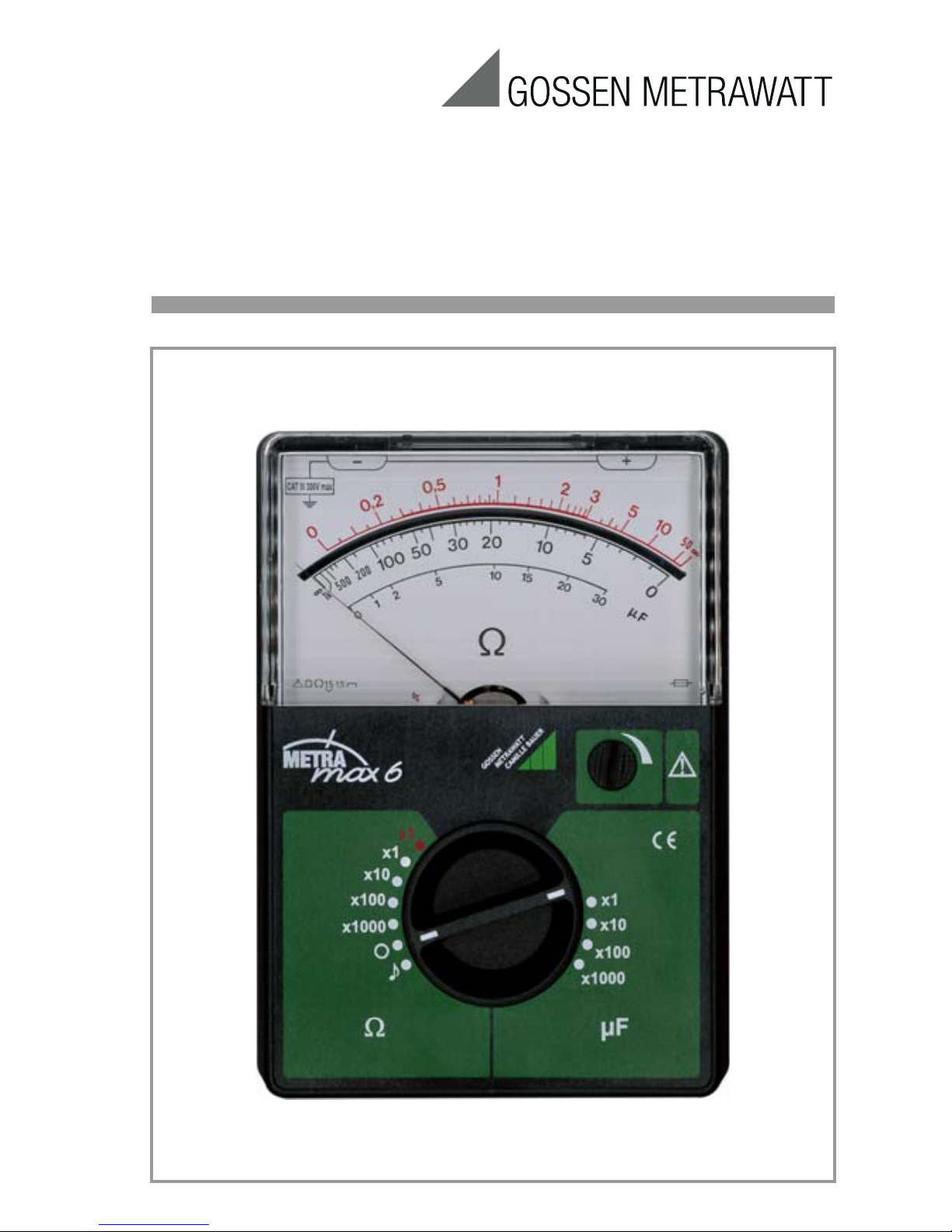
METRAmax 6
Analog Multimeter
3-348-602-02
6/10.15
Page 2
2 GMC-I Messtechnik GmbH
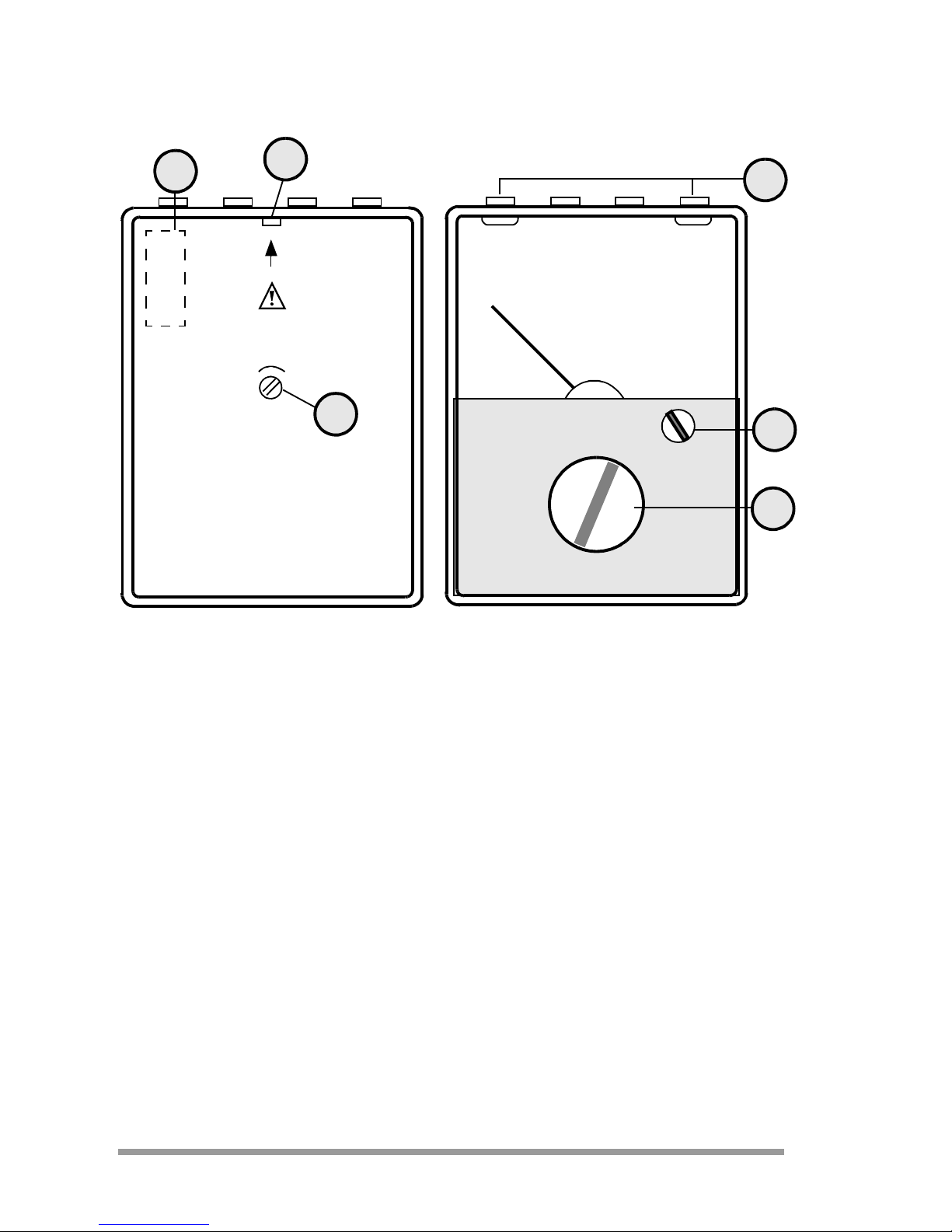
Operating Controls
1 Range selector switch
2 Rotary knob to adjust the full-scale deflection
3 Socket connectors
4 Battery compartment
5 Nose to open the meter
6 Adjustment screw for the mechanical zero
(
∞ on black scale)
6
1
2
3
5
4
1,5 V
R6
Page 3

GMC-I Messtechnik GmbH 3
Table of Contents
Page
1 Safety Features and Precautions ........................................ 4
2 Description ......................................................................... 6
3 Operation ............................................................................ 7
3.1 Inserting the Battery .......................................................................... 7
3.2 Checking the Mechanical Zero ........................................................... 8
3.3 Battery Test ...................................................................................... 8
4 Measurement ..................................................................... 9
4.1 Resistance Measurement .................................................................. 9
4.1.1 Measuring in the Range up to 50 Ω (Ω x 1, red) .............................. 10
4.1.2 Measuring in the Ranges up to 1 MΩ
(Ω x 1/10/100/1000, black) ............................................................ 10
4.2 Rough Capacitance Measurement .................................................... 11
4.3 Diode and Transistor Test ................................................................ 12
4.4 Acoustic Continuity Test .................................................................. 13
5 End of Measurement ........................................................ 13
6 Characteristic Values ........................................................ 14
7 Maintenance ..................................................................... 16
7.1 Battery ........................................................................................... 16
7.2 Fusible Link .................................................................................... 16
7.2.1 Fuse Replacement .......................................................................... 16
7.3 Housing .......................................................................................... 17
7.4 Device Return and Environmentally Compatible Disposal ................... 17
8 Repair and Replacement Parts Service
Calibration Center and Rental Instrument Service ........... 18
9 Product Support ................................................................ 20
Page 4

4 GMC-I Messtechnik GmbH
1 Safety Features and Precautions
This instrument fulfills the requirements of the applicable
European and national EC guidelines. We confirm this with
the CE marking. The relevant declaration of conformity can
be obtained from GMC-I Messtechnik GmbH.
The analog multimeter METRAmax 6 is manufactured in
accordance with safety regulations IEC 61010-1/EN
61010-1/VDE 0411-1. When used for its intended purpose, the safety of the operator, as well as that of the
instrument, is assured. Their safety is however not guaranteed if the instrument is used improperly or handled carelessly. It is therefore imperative that you read the operating
instructions thoroughly and carefully before placing the
METRAmax 6 into service, and that you follow all instructions contained therein.
Observe the following safety precautions:
• The instrument may only be operated by persons who
are capable of recognizing contact hazards and taking
the appropriate safety precautions.
• Contact hazards exist anywhere, where voltages of
greater than 30 V may occur (effective value).
• Be prepared for the occurrence of unexpected voltages
at devices under test (e.g. defective devices).
For example, capacitors can be dangerously charged!
• Housing and measurement cables may not be damaged, e.g. by cracks or ruptures.
• No measurements may be made with the METRAmax 6 in
electrical circuits with corona discharge (high-voltage).
• Special care is required when measurements are made
in HF electrical circuits. Dangerous pulsating voltages
may be present.
Page 5
GMC-I Messtechnik GmbH 5
• Measurements under moist ambient conditions are not allowable. Hands, shoes, floor and workplace must be dry.
• Be absolutely certain that the measuring ranges are not
overloaded beyond their allowable capacities.
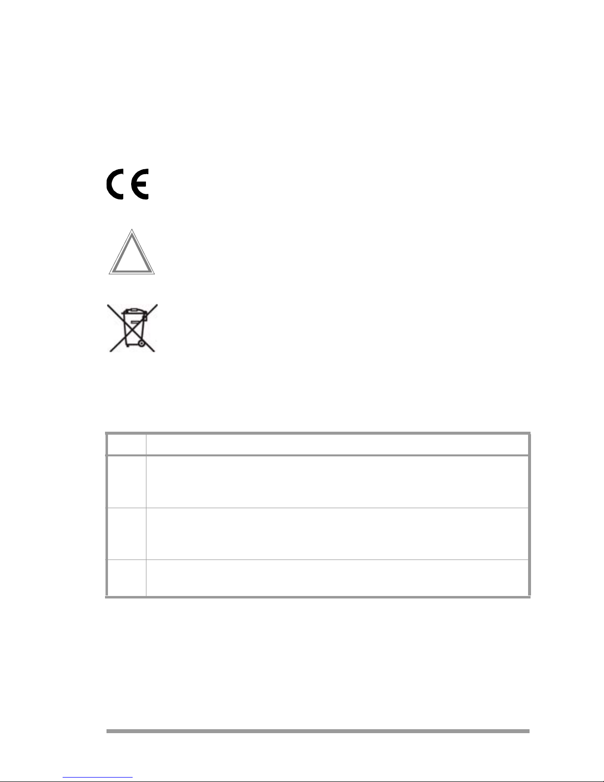
Meaning of Symbols on the Instrument
indicates EC conformity
Warning concerning a point of danger.
(Attention: observe documentation!)
This device may not be disposed of with the trash.
Further information regarding the WEEE mark can be
accessed on the Internet at
www.gossenmetrawatt.com by entering the search
term ’WEEE’.
Measuring Categories and their Significance per IEC 61010-1
The measuring category and the maximum rated voltage
which is printed on the device apply to your measuring
instrument, 300 V CAT III.
CAT Definition
I
Measurements in electrical circuits which are not directly connected to
the mains: e.g. electrical systems in motor vehicles and aircraft,
batteries etc.
II
Measurements in electrical circuits which are electrically connected to the
low-voltage mains: via plug, e.g. in household, office and laboratory
applications
III
Measurements in building installations: stationary consumers, distributor
terminals, devices connected permanently to the distributor
!
Page 6

6 GMC-I Messtechnik GmbH
2 Description
The METRAmax 6 is a battery-powered ohmmeter. It
excels by its handy size, ease of use, and a large measuring span. It is meant for measurement of resistances
between 0.05
Ω and 1 MΩ, for rough capacitance mea-
surements between 1
μF and 30,000 μF, and for continuity
tests with beeper.
The METRAmax 6 offers 9 measuring ranges for resistance
and capacitance measurements. The measuring ranges
are selected with a range switch.
The meter has a rugged movement with spring-loaded
jewels. It is widely insensitive to vibrations and shocks.
The scale is mirror-backed for exact reading of the measured values.
The measuring range
Ω x 1, marked in red, and the scale
marked in red are provided for measurements of small
resistance values (0.05 Ω bis 50 Ω). To measure higher
resistance values, there are 4 measuring ranges which
have a common black scale.
A part of the two scale arcs is boldly marked. The measuring error, referred to the actual resistance value, is smallest
on these marked indicating ranges.
For rough capacitance measurements, there are 4 measuring ranges with a common scale.
A beeper is incorporated for audible continuity tests.
The connectors are protected against accidental contact. It
is recommended to use measuring leads with shockproof
connection plugs (4 mm diameter).
Page 7

GMC-I Messtechnik GmbH 7
3 Operation
Attention!
!
Only voltage-free devices under test may be measured!
Prior to each measurement, check mechanical
zero and full-scale deflection.
3.1 Inserting the Battery
Prior to starting the METRAmax 6, insert a 1.5 V mignon
cell into the battery compartment. This requires removal of
the lower part of the case.
Attention!
!
Disconnect the measurement cables from the
measuring circuit before opening the meter!
➭ Press the nose (5) on the rear of the meter inwards,
using an adequate tool, and remove the lower part.
➭ Insert a leakproof 1.5 V mignon cell according to IEC
R6 into the battery compartment (4), paying attention to
the polarity markings. Verify that reliable contact is
made.
➭ Replace the lower part of the case and press the two
parts together until they engage.
Page 8

8 GMC-I Messtechnik GmbH
3.2 Checking the Mechanical Zero
➭ Place the METRAmax 6 into a horizontal position.
➭ Set the range selector switch (1) to the "O" position
(OFF).
➭ The pointer has to be exactly over the bar code of the
full-scale deflection (∞ on the black scale).
➭ Correct deviations with the adjusting screw (6) on the
rear of the meter with a screwdriver, if required.
3.3 Battery Test
➭ Set the range selector switch (1) to the "Ω x 1" position
(red marking).
➭ With the rotary knob (2), adjust the movement pointer
on the red scale to full-scale deflection (∞).
If the pointer can no longer be adjusted to full-scale deflection, or if the indication is instable after the adjustment, the
battery is exhausted and has to be replaced with a new
one, see chapter 3.1.
Page 9

GMC-I Messtechnik GmbH 9
4 Measurement
4.1 Resistance Measurement
Resistance is measured with DC voltage from the inserted
1.5 V mignon cell. The maximum measuring currents at
full-scale deflection, with a battery voltage of 1.5 V, are
listed in the range table (see chapter 6 "Characteristic Values").
If possible, select the measuring range in such a way that
indication is in the range of the boldly drawn scale arc. The
measuring error, referred to the actual resistance value, is
smallest in this range.
During prolonged resistance measurements, occasionally
check for full-scale deflection (0 Ω or ∞).
When switching the range selector switch (1) to another
resistance range, always check for full-scale deflection and
adjust with the rotary knob (2), if required.
Page 10

10 GMC-I Messtechnik GmbH
4.1.1 Measuring in the Range up to 50 Ω (Ω x 1, red)
➭ Set the range selector switch (1) to Ω x 1 (red marking).
➭ With the rotary knob (2), adjust the pointer to full-scale
deflection (
∞) on the red scale.
➭ Connect the unknown resistance R
x
to be measured
and read the resistance value on the red scale.
4.1.2 Measuring in the Ranges up to 1 MΩ
(Ω x 1/10/100/1000, black)
➭ Set the range selector switch (1) to one of the measur-
ing ranges Ω x 1 ... Ω x 1000, depending upon the resistance value to be measured.
➭ Short-circuit the measuring leads.
➭ With the rotary knob (2), set the pointer to full-scale
deflection (0 Ω) on the black scale.
➭ Connect the resistance R
X
to be measured to the measuring leads and read the resistance value on the black
scale. The indicated value must be multiplied by the
specified factor in line with the selected measuring
range.
R
X
Page 11

GMC-I Messtechnik GmbH 11
4.2 Rough Capacitance Measurement
➭ Set the range selector switch (1) to one of the measur-
ing ranges μFx1...μF x 1000, depending upon the
capacitance value to be measured.
➭ Capacitance is measured according to the ballistic
method. Connect the capacitor a few times to the measuring leads with changing polarity and read the largest
pointer deflection on the μF scale.
With this method, the capacitance of the capacitor to be
measured can only roughly be determined. The measured
value can deviate from the actual value by up to ±25 %.
Page 12

12 GMC-I Messtechnik GmbH
4.3 Diode and Transistor Test
The resistance range Ω x 1000 is suited for a rough functional check on semiconductor elements. A resistance
measurement is an easy way to find a short circuit or an
interruption on a diode and/or a diode junction between
base, collector and emitter. The polarity of a diode and the
base connection of a transistor can also be determined by
this test.
This measurement does not destroy semiconductor elements to be tested as the 1.75 V voltage and the 100 μA
current are not exceeded.
Page 13

GMC-I Messtechnik GmbH 13
4.4 Acoustic Continuity Test
The continuity test (range selector switch (1) set to position
is suitable for testing low-ohmic connections with a
resistance value of ≤1.5 Ω.
No external voltage must be applied during the measure-
ment!
The forward direction of semiconductor elements should
not be tested by the audible continuity test but only
according to the deflection method (see chapter 4.3).
When using the audible continuity test, inductive voltage
spikes appear at the meter connectors which could damage the semiconductors.
5 End of Measurement
After the measurement, the range selector switch (1)
should be set to "0" to conserve the battery life.
Page 14

14 GMC-I Messtechnik GmbH
6 Characteristic Values
Measuring Ranges
1)
with a battery voltage 1.5 V
Acoustic Continuity Test
Response range 0 ... 1.5 Ω (integrated beeper)
Response current 365 mA
Operating current 170 mA
Accuracy
Error limit ±1.5 % of scale length
± 8.2 % as a function of the actual
resistance value in the display
range with boldly marked scale arc.
Reference Conditions
Ambient temperature +20 °C
Position of use horizontal
Resistance
Measuring Range
Span
Mid-scale
Value
(Ri)
Max. Measuring
Current
I
max
1)
approx.
Ω x 1
(red scale)
0.05 Ω ... 50 Ω 1 Ω 75 mA
Ω x1 1 Ω ... 1 kΩ 20 Ω 75 mA
Ω x 10 10 Ω ... 10 kΩ 200 Ω 7.5 mA
Ω x 100 100 Ω ... 100 kΩ 2 kΩ 0.75 mA
Ω x 1000 1 kΩ ... 1MΩ 20 kΩ 0.075 mA
Capacitance
Measuring Range
Measuring Range Span
Max. Measuring
Current
I
max.
1)
μF x 1 0 ... 30 μF 0.075 mA
μF x 10 0 ... 300 μF 0.75 mA
μF x 100 0 ... 3 000 μF 7.5 mA
μF x 1 000 0 ... 30 000 μF 75 mA
Page 15

GMC-I Messtechnik GmbH 15
Display
Scale mirror-backed
Scale length approx. 90 mm
Pointer deflection ∠ 0° ... 100°
Ambient Conditions
Storage temperatures –25 ... 65 °C (without battery)
Relative humidity
max. 75%, no condensation allowed
Power Supply
Battery 1 mignon cell 1.5 V per IEC LR6 (AA),
leak-proof
Overload Protection
Fusible link F 6.3 H/250 V per DIN VDE 0820
part 22/EN 60127-2, embedded
Electrical Safety
Protection class II per IEC 61010-1/EN 61010-1/
VDE 0411-1
Measuring category CAT III 300 V max
Contamination degree 2
Test voltage 2 kV∼
EMC Electromagnetic compatibility
Interference emission/
interferene immunity
EN 61326-1
Mechanical Design
Protection Housing IP50, terminals IP20
Extract from table on the meaning of IP codes
Dimensions 100 mm x 140 mm x 35 mm
Weight approx. 0.3 kg (without battery)
IP XY
(1
st
digit X)
Protection against
foreign object entry
IP XY
(2nd digit Y)
Protection against the
penetration of water
2 ≥ 12,5 mm ∅ 0 not protected
5 dust protected 0 not protected
Page 16

16 GMC-I Messtechnik GmbH
7 Maintenance
7.1 Battery
The state of the battery should be ckecked from time to
time. An exhausted or deteriorating battery must not
remain in the battery compartment. Check and replace the
battery as described in chapter 3.1 on page 7.
7.2 Fusible Link
The holder for the fuse link is soldered to the circuit board.
See chapter 6, "Overload Protection" for the specified fuse.
7.2.1 Fuse Replacement
• Disconnect the meter from the measuring circuit!
• Remove the lower part of the case, see chapter 3.1 on
page 7.
• Changing the fuse it is possible to put the holder carefully to side or to desolder it.
Attention!
!
Please make definitely sure that only the specified
fuse is inserted! Using a fuse with other cut-out
characteristics, other nominal current or other
switching capacity may endanger the user and
damage protective diodes, resistors and other
components.
The use of mended fuses or short-circuiting of the fuse
holder is not permitted.
Page 17

GMC-I Messtechnik GmbH 17
7.3 Housing
The meter may only be cleaned with a soft cloth or brush.
Possible static charges of the glass pane can be removed
with an antistatic agent or a moist cloth.
7.4 Device Return and Environmentally Compatible Disposal
The METRAmax 6 is a category 9 product (monitoring and
control instrument) in accordance with ElektroG (German
Electrical and Electronic Device Law). This device is subject
to the RoHS directive. Furthermore, we make reference to
the fact that the current status in this regard can be
accessed on the Internet at www.gossenmetrawatt.com
by entering the search term WEEE.
We identify our electrical and electronic devices in
accordance with WEEE 2012/19/EU and
ElektroG with the symbol shown to the right per
DIN EN 50419.
These devices may not be disposed with the trash. Please
contact our service department regarding the return of old
devices, see chapter 8 on page 18.
If you use batteries or rechargeable batteries in your instru-
ment or accessories which no longer function properly,
they must be duly disposed of in compliance with the
applicable national regulations.
Batteries or rechargeable batteries may contain harmful
substances or heavy metal such as lead (PB), cadmium
(CD) or mercury (Hg).
They symbol shown to the right indicates that batteries or rechargeable batteries may not be disposed of with the trash, but must be delivered to
collection points specially provided for this purpose.
Pb Cd Hg
Page 18

18 GMC-I Messtechnik GmbH
8 Repair and Replacement Parts Service
Calibration Center *
and Rental Instrument Service
When you need service, please contact:
GMC-I Messtechnik GmbH
Service Center
Thomas-Mann-Strasse 20
90471 Nürnberg • Germany
Phone +49 911 817718-0
Fax +49 911 817718-253
E-Mail service@gossenmetrawatt.com
www.gmci-service.com
This address is only valid in Germany.
Please contact our representatives or subsidiaries for service in other countries.
* DAkkS Calibration Laboratory
for Electrical Quantities D-K-15080-01-01
accredited per DIN EN ISO/IEC 17025
Accredited measured quantities: direct voltage, direct current values, DC
resistance, alternating voltage, alternating current values, AC active
power, AC apparent power, DC power, capacitance, frequency and temperature
Page 19

GMC-I Messtechnik GmbH 19
Competent Partner
GMC-I Messtechnik GmbH is certified in accordance with
DIN EN ISO 9001:2008.
Our DAkkS calibration laboratory is accredited by the
Deutsche Akkreditierungsstelle GmbH (National accreditation body for the Federal Republic of Germany) in accordance with DIN EN ISO/IEC 17025:2005 under registration
number D-K-15080-01-01.
We offer a complete range of expertise in the field of
metrology: from test reports and proprietary calibration certifi-
cates right on up to DAkkS calibration certificates.
Our spectrum of offerings is rounded out with free test
equipment management.
An on-site DAkkS calibration station is an integral part of our
service department. If errors are discovered during
calibration, our specialized personnel are capable of completing repairs using original replacement parts.
As a full service calibration laboratory, we can calibrate
instruments from other manufacturers as well.
Page 20

Edited in Germany • Subject to change without notice • A pdf version is available on the
Internet
GMC-I Messtechnik GmbH
Südwestpark 15
90449 Nürnberg •
Germany
Phone +49 911 8602-111
Fax +49 911 8602-777
E-Mail
info@gossenmetrawatt.com
www.gossenmetrawatt.com
9 Product Support
When you need support, please contact:
GMC-I Messtechnik GmbH
Product Support Hotline
Phone +49 911 8602-0
Fax +49 911 8602-709
E-Mail support@gossenmetrawatt.com
 Loading...